Loading ...
Loading ...
Loading ...
– 12 –
9. OPERATING THE SHREDDER
NOTE:
Your fingers must never enter the in-feed chute.
Never use the tool if the hopper is not fitted.
Do not over reach.
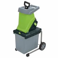
9.3 COLLECTING THE SHREDDED
MATERIAL – FIG. 9
Shut-off the power unit before attaching or removing
the box.
You can use either the collection box supplied or
place the shredder on a tarpaulin sheet to catch the
shredded material.
When using the collection box, you need to lift up the
collection box catch (5) and slide the collection box
to the appropriate location and release catch to
secure.
Warning: The ventilation slots on the machine body
must never be covered by the collection box or
shredded material.
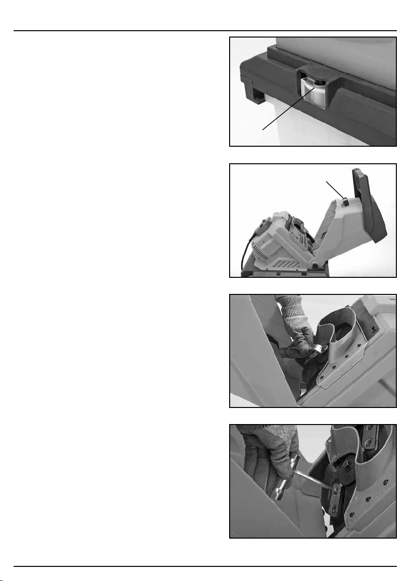
9.4 REPLACING BLADES – FIGS. 10 - 12
1. Ensure that the shredder is switched off and
disconnected from the mains supply.
2. Remove the top feed housing by unscrewing the
reamer knob (3) securing it to the body of the
machine.
3. The blades have two cutting edges. When the
blades become worn they can be reversed to use
the second cutting edge.
4. It is recommended that work gloves be used when
replacing the blades.
5. Clean the blades and the blade disc of any debris
of residue before refitting the blades.
6. Lock the blade disc using hex spanner. Unscrew
the two inner hexagonal headed screws and note
the position of the cutting angle of the blade.
7. Remove the blade and rotate it through 180
degrees and fit the blade to the blade disc
ensuring that the ground cutting edge is facing
downwards.
8. Repeat this for the other blade.
When both cutting edges of the blade have become
worn they must be replaced as a pair. The blades can
be re-sharpened, but this must be done by an
experienced person using an oil stone. We do not
recommend this be done as the weight of each blade
is critical to maintain the balance of the cutting disc.
Any imbalance could cause damage to the machine
and possible injury to the operator.
FIG. 9
(5)
FIG. 10
FIG. 11
FIG. 12
(3)
Loading ...
Loading ...
Loading ...