Loading ...
Loading ...
Loading ...
STEP 7 Finalize Installation
• Connect power.
• Push selector switch to ON.
• Wait for rinsing cycle, approximately 5 minutes, to be
sure the icemaker is operating properly.
Pub. No. 49-60155 SPECIFICATIONS SUBJECT TO CHANGE WITHOUT NOTICE DWG. NO. 197D4493P001
(N.D. 305) 11/01
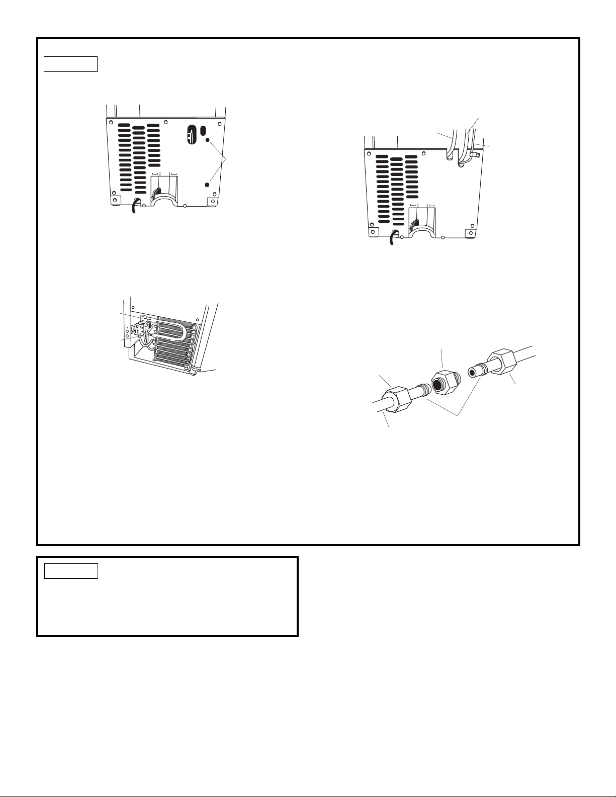
STEP 6 Connect Water Supply
• Feed water supply tubing through one of the two
access holes in the rear cover.
• Slide the icemaker into its permanent location.
IMPORTANT: Check to be sure water and drain lines
do not kink or bind. This could interfere with
icemaker operation.
• Bend the tubing to meet the connection at the water
valve inlet at the front.
• Remove the water valve inlet cover and attach copper
tubing with a compression nut and sleeve.
• Check to be sure copper tubing does not touch the
side wall or other parts inside the cabinet.
• Turn on the water and check all connections for
leaks.
Water
Line
Access
Holes
Water
Inlet
Water
Outlet
• Check to be sure copper tubing does not touch the
side wall or other parts inside the cabinet.
• Turn on the water and check all connections for
leaks.
For connection in Front at Water Valve:
• For threaded connection, use ferrule and compres-
sion nut to secure the line as shown on page 1.
• For water tube exiting rear access cover, connect
water line using 1/4" union or coupling.
For Water Connection at Rear:
Water
Supply
Line
Drain Hose
From Drain
Pump
Vent Hose
From Drain Pump
Coupling
(Not Supplied)
Nut
(Supplied)
Ferrule
(Not Supplied)
Line to
Icemaker
Nut
(Supplied)