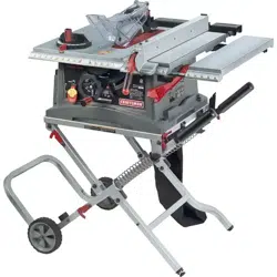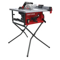

10" Table Saw
Sierra de Mesa de 254 mm (10 pulgados)
CMXETAX69434502
INSTRUCTION MANUAL | MANUAL DE INSTRUCTIONES
IF YOU HAVE QUESTIONS OR COMMENTS, CONTACT US.
SI TIENE DUDAS O COMENTARIOS, CONTÁCTENOS.
1-888-331-4569 WWW.CRAFTSMAN.COM
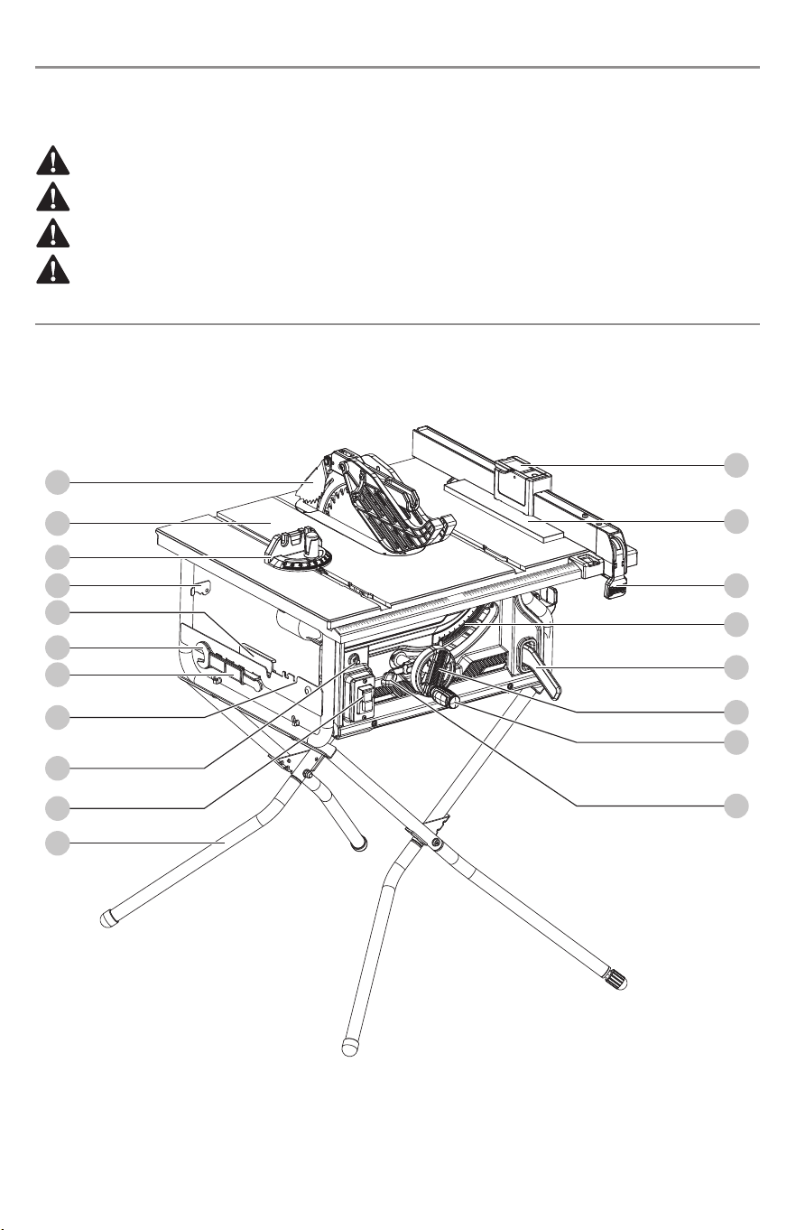
Fig. 1
0
01
1
2
3
4
5
6
7
8
9
10
2
3
4
5
6
7
8
9
10
11
12
ENGLISH
1
Denitions: Safety Alert Symbols and Words
This instruction manual uses the following safety alert symbols and words to alert you to hazardous situations and your risk
of personal injury or property damage.
DANGER: Indicates an imminently hazardous situation which, if not avoided, will result in death or serious injury.
WARNING: Indicates a potentially hazardous situation which, if not avoided, could result in death or serious injury.
CAUTION: Indicates a potentially hazardous situation which, if not avoided, may result in minor or moderate injury.
(Used without word) Indicates a safety related message.
NOTICE: Indicates a practice not related to personal injury which, if not avoided, may result in property damage.
18
17
16
14
13
9
12
15
11
10
19
1
2
3
5
6
7
8
4
0
01
1
2
3
4
5
6
7
8
9
10
2
3
4
5
6
7
8
9
10
11
12
0
01
1
2
3
4
5
6
7
8
9
10
2
3
4
5
6
7
8
9
10
11
12
ENGLISH
2
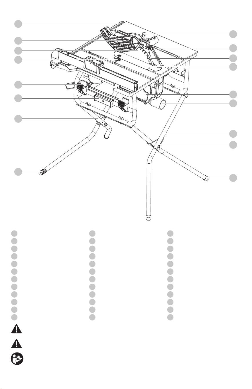
Components
1
Locking knob (for sub fence)
2
Sub fence assembly
3
Rip fence locking handle
4
Bevel scale
5
Push stick
6
Height/bevel adjusting handwheel
7
Height adjusting handle
8
Bevel locking lever
9
Lower leg
10
On/O switch
11
Overload reset switch
12
Blade guard storage
13
Blade wrench storage
14
Blade wrench
15
Miter gauge storage
16
Anti-kickback pawls storage
17
Miter gauge
18
Working table
19
Anti-kickback pawls
20
Miter gauge locking knob
21
Miter gauge groove
22
Riving knife
23
Table insert
24
Small bae
25
Dust chute
26
Outer upper leg
27
Back angle plate
28
Foot
29
Leveling foot
30
Inner upper leg
31
Sub fence assembly storage
32
Rip fence storage
33
Locking knob (for table insert)
34
Saw blade
35
Blade guard
36
Scale
WARNING: Read all safety warnings and all instructions. Failure to follow the warnings and instructions may result in
electric shock, re and/or seriousinjury.
WARNING: To reduce the risk of injury, read the instructionmanual.
If you have any questions or comments about this or any product, call CRAFTSMAN toll free at: 1-888-331-4569.
36
35
33
32
31
29
30
34
20
21
22
23
24
25
26
27
28
WARNING: Never modify the product or any part of it.
Damage or personal injury couldresult.
ENGLISH
3
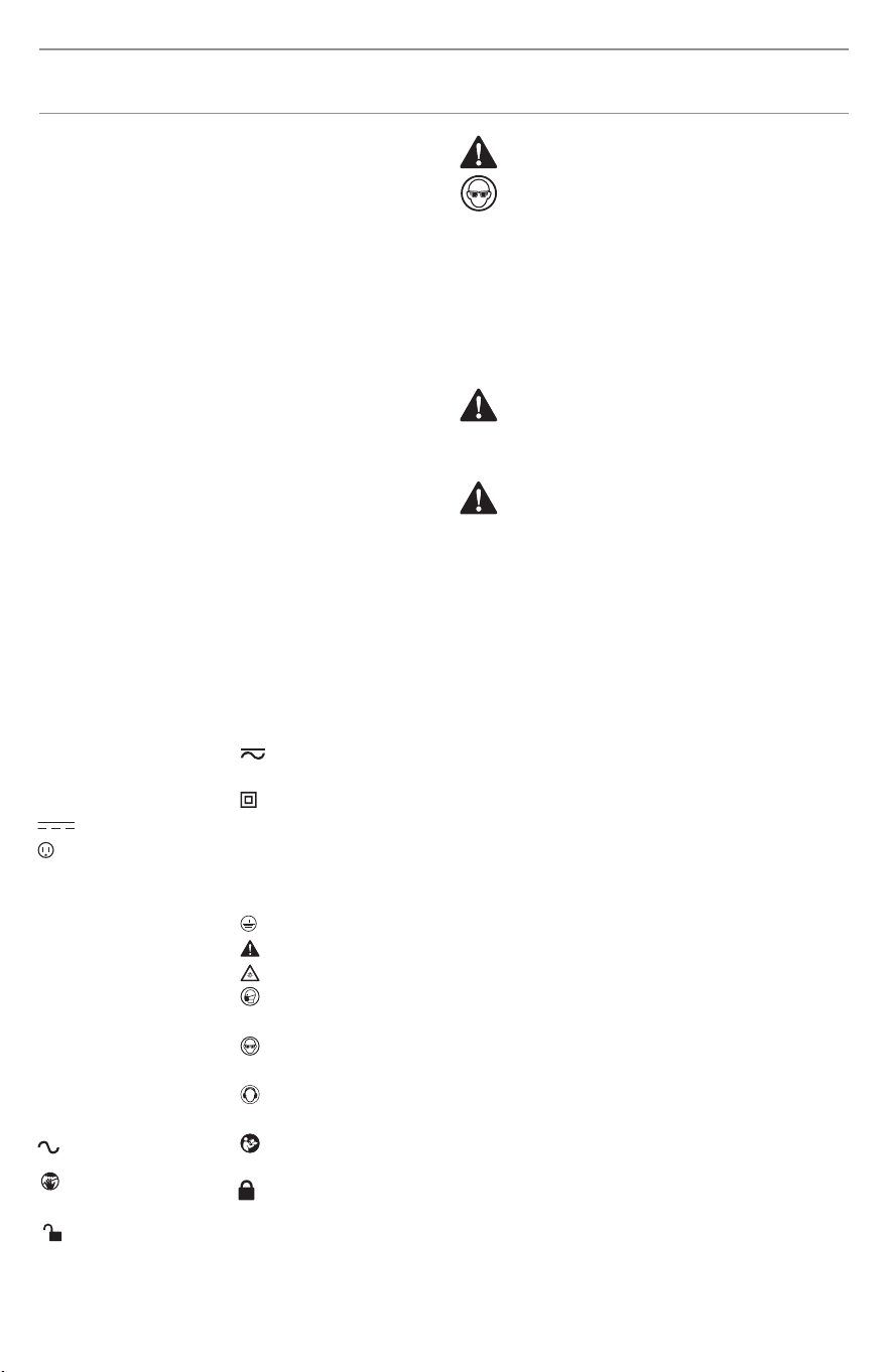
The label on your tool may include the following symbols. The
symbols and their denitions are asfollows:
V ......................... volts
Hz ........................ hertz
min ...................... minutes
or DC ....... direct current.
...................... Class I Construction
(grounded)
…/min .............. per minute
BPM .................... beats per minute
IPM ..................... impacts per minute
RPM .................... revolutions per
minute
sfpm ................... surface feet per
minute
SPM .................... strokes per minute
A ......................... amperes
W ........................ watts
or AC ........... alternating current
..................... Lock / to tighten
or secure.
..................... Unlock / to loosen.
..................... Danger! keep hands
away from blade.
or AC/DC ..... alternating or
direct current
...................... Class II
Construction
(double insulated)
n
o
....................... no load speed
n ......................... rated speed
...................... earthing terminal.
..................... safety alert symbol.
..................... visible radiation.
..................... wear respiratory
protection.
..................... wear eye
protection.
..................... wear hearing
protection.
..................... read all
documentation
10" Table Saw
CMXETAX69434502
IMPORTANT SAFETY INFORMATION
SAFETY SYMBOLS
WARNING: The operation of any power tool can
result in foreign objects being thrown into your eyes,
which can result in severe eye damage. Before
beginning power tool operation, always wear safety
goggles or safety glasses with side shields and a
full-face shield when needed. We recommend a Wide
Vision Safety Mask for use over eyeglasses or standard
safety glasses with side shields. Always use eye
protection which is marked to comply with
ANSI Z87.1. Everyday eyeglasses have only impact
resistant lenses. They are NOT safety glasses.
WARNING: To ensure safety and reliability, all repairs
should be performed by a qualied service technician.
WARNING: Read all safety warnings, instructions,
illustrations and specications provided with
this power tool. Failure to follow all instructions
listed below may result in electric shock, re and/or
serious injury.
Read and understand all of the safety precautions, warnings
and operating instructions in the Instruction Manual before
operating or maintaining this power tool.
Most accidents that result from power tool operation and
maintenance are caused by the failure to observe basic safety
rules or precautions. An accident can often be avoided by
recognizing a potentially hazardous situation before it occurs,
and by observing appropriate safety procedures.
Basic safety precautions are outlined in the “SAFETY” section of
this Instruction Manual and in the sections which contain the
operation and maintenance instructions.
Hazards that must be avoided to prevent bodily injury or
machine damage are identied by WARNINGS on the power
tool and in this Instruction Manual.
NEVER use this power tool in a manner that has not been
specically recommended by CRAFTSMAN.
SAFETY INSTRUCTIONS
Save all warnings and instructions for future reference.
The term “power tool” in the warnings refers to your mains-
operated (corded) power tool or battery operated (cordless)
power tool.
1) Work area safety
a) Keep work area clean and well lit. Cluttered or dark areas
invite accidents.
b) Do not operate power tools in explosive atmospheres,
such as in the presence of ammable liquids, gases or
dust. Power tools create sparks which may ignite the
dust or fumes.
c) Keep children and bystanders away while operating a
power tool. Distractions can cause you to lose control.
2) Electrical safety
a) Power tool plugs must match the outlet. Never modify
the plug in any way. Do not use any adapter plugs with
earthed (grounded) power tools. Unmodied plugs and
matching outlets will reduce risk of electric shock.
b) Avoid body contact with earthed or grounded surfaces,
such as pipes, radiators, ranges and refrigerators. There
is an increased risk of electric shock if your body is
earthed or grounded.
c) Do not expose power tools to rain or wet conditions.
Water entering a power tool will increase the risk of
electric shock.
d) Do not abuse the cord. Never use the cord for carrying,
pulling or unplugging the power tool. Keep cord away
from heat, oil, sharp edges or moving parts. Damaged
or entangled cords increase the risk or electric shock.
e) When operating a power tool outdoors, use an extension
cord suitable for outdoor use. Use of a cord suitable for
outdoor use reduce the risk of electric shock.
f) If operating a power tool in a damp location is
unavoidable, use a ground fault circuit interrupter (GFCI)
SAVE THESE INSTRUCTIONS AND MAKE
THEM AVAILABLE TO OTHER USERS AND
OWNERS OF THIS TOOL!

4
ENGLISH
WARNING: Read and understand all instructions.
Failure to follow all instructions listed below, may
result in electric shock, and/or serious personal injury.
Save all warnings and instructions for future reference.
protected supply. Use of an GFCI reduces the risk of
electric shock.
3) Personal safety
a) Stay alert, watch what you are doing and use common
sense when operating a power tool. Do not use a power
tool while you are tired or under the inuence of drugs,
alcohol or medication. A moment of inattention while
operating power tools may result in serious personal
injury.
b) Use personal protective equipment. Always wear eye
protection. Protective equipment such as dust mask,
non-skid safety shoes, hard hat, or hearing protection
used for appropriate conditions will reduce personal
injuries.
c) Prevent unintentional starting. Ensure the switch is in
the o-position before connecting to power source
and/or battery pack, picking up or carrying the tool.
Carrying power tools with your nger on the switch or
energizing power tools that have the switch on invites
accidents.
d) Remove any adjusting key or wrench before turning the
power tool on. A wrench or a key left attached to a
rotating part of the power tool may result in personal
injury.
e) Do not overreach. Keep proper footing and balance at
all times. This enables better control of the power tool in
unexpected situations.
f) Dress properly. Do not wear loose clothing or jewelry.
Keep your hair, clothing and gloves away from moving
parts. Loose clothes, jewelry or long hair can be caught
in moving parts.
g) If devices are provided for the connection of dust
extraction and collection facilities, ensure these are
connected and properly used. Use of dust collection can
reduce dust-related hazards.
h) Do not let familiarity gained from frequent use of tools
allow you to become complacent and ignore tool safety
principles. A careless action can cause severe injury
within a fraction of a second.
4) Power tool use and care
a) Do not force the power tool. Use the correct power tool
for your application. The correct power tool will do the
job better and safer at the rate for which it was designed.
b) Do not use the power tool if the switch does not turn it
on and o. Any power tool that cannot be controlled
with the switch is dangerous and must be repaired.
c) Disconnect the plug from the power source and/or
remove the battery pack, if detachable, from the power
tool before making any adjustments, changing
accessories, or storing power tools. Such preventive
safety measures reduce the risk of starting the power
tool accidentally.
d) Store idle power tools out of the reach of children and
do not allow persons unfamiliar with the power tool or
these instructions to operate the power tool. Power tools
are dangerous in the hands of untrained users.
e) Maintain power tools and accessories. Check for
misalignment or binding of moving parts, breakage of
parts and any other condition that may aect the
power tool’s operation. If damaged, have the power tool
repaired before use. Many accidents are caused by
poorly maintained power tools.
f) Keep cutting tools sharp and clean. Properly maintained
cutting tools with sharp cutting edges are less likely to
bind and are easier to control.
g) Use the power tool, accessories and tool bits, etc., in
accordance with these instructions, taking into account
the working conditions and the work to be performed.
Use of the power tool for operations dierent from those
intended could result in a hazardous situation.
h) Keep handles and grasping surfaces dry, clean and free
from oil and grease. Slippery handles and grasping
surfaces do not allow for safe handling and control of
the tool in unexpected situations.
5) Service
a) Have your power tool serviced by a qualied repair
person using only identical replacement parts. This will
ensure that the safety of the power tool is maintained.
1) Guarding related warnings
a) Keep guards in place. Guards must be in working order
and be properly mounted. A guard that is loose,
damaged, or is not functioning correctly must be
repaired or replaced.
b) Always use saw blade guard, riving knife and
anti-kickback device for every throughcutting operation.
For throughcutting operations where the saw blade
cuts completely through the thickness of the workpiece,
the guard and other safety devices help reduce the risk
of injury.
c) Immediately reattach the guarding system after
completing an operation (such as rabbeting, dadoing or
resawing cuts) which requires removal of the guard,
riving knife and/or anti-kickback device. The guard,
riving knife, and anti-kickback device help to reduce the
risk of injury.
d) Make sure the saw blade is not contacting the guard,
riving knife or the workpiece before the switch is turned
on. Inadvertent contact of these items with the saw
blade could cause a hazardous condition.
e) Adjust the riving knife as described in this instruction
manual. Incorrect spacing, positioning and alignment
can make the riving knife ineective in reducing the
likelihood of kickback.
f) For the riving knife and anti-kickback device to work,
they must be engaged in the workpiece. The riving knife
and anti-kickback device are ineective when cutting
workpieces that are too short to be engaged with the
riving knife and anti-kickback device. Under these
conditions a kickback cannot be prevented by the riving
knife and anti-kickback device.
g) Use the appropriate saw blade for the riving knife. For
Safety instructions for table saws

ENGLISH
5
the riving knife to function properly, the saw blade
diameter must match the appropriate riving knife and
the body of the saw blade must be thinner than the
thickness of the riving knife and the cutting width of the
saw blade must be wider than the thickness of the riving
knife.
2) Cutting procedures warnings
a) DANGER: Never place your ngers or hands in the
vicinity or in line with the saw blade. A moment of
inattention or a slip could direct your hand towards the
saw blade and result in serious personal injury.
b) Feed the workpiece into the saw blade or cutter only
against the direction of rotation. Feeding the workpiece
in the same direction that the saw blade is rotating
above the table may result in the workpiece, and your
hand, being pulled into the saw blade.
c) Never use the miter gauge to feed the workpiece when
ripping and do not use the rip fence as a length stop
when cross cutting with the miter gauge. Guiding the
workpiece with rip fence and the miter gauge at the
same time increases the likelihood of saw blade binding
and kickback.
d) When ripping, always apply the workpiece feeding force
between the fence and the saw blade. Use a push stick
when the distance between the fence and the saw blade
is less than 150 mm, and use a push block when this
distance is less than 50 mm. “Work helping” devices will
keep your hand at a safe distance from the saw blade.
e) Use only the push stick provided by the manufacturer or
constructed in accordance with the instructions. This
push stick provides sucient distance of the hand from
the saw blade.
f) Never use a damaged or cut push stick. A damaged
push stick may break causing your hand to slip into the
saw blade.
g) Do not perform any operation “freehand”. Always use
either the rip fence or the miter gauge to position and
guide the workpiece. “Freehand” means using your
hands to support or guide the workpiece, in lieu of a rip
fence or miter gauge. Freehand sawing leads to
misalignment, binding and kickback.
h) Never reach around or over a rotating saw blade.
Reaching for a workpiece may lead to accidental
contact with the moving saw blade.
i) Provide auxiliary workpiece support to the rear and/or
sides of the saw table for long and/or wide workpieces
to keep them level. A long and/or wide workpiece has a
tendency to pivot on the table’s edge, causing loss of
control, saw blade binding and kickback.
j) Feed workpiece at an even pace. Do not bend or twist
the workpiece. If jamming occurs, turn the tool o
immediately, unplug the tool then clear the jam.
Jamming the saw blade by the workpiece can cause
kickback or stall the motor.
k) Do not remove pieces of cut-o material while the saw is
running. The material may become trapped between
the fence or inside the saw blade guard and the saw
blade pulling your ngers into the saw blade. Turn the
saw o and wait until the saw blade stops before
removing material.
l) Use an auxiliary fence in contact with the table top
when ripping workpieces less than 2 mm thick. A thin
workpiece may wedge under the rip fence and create a
kickback.
3) Kickback causes and related warnings
Kickback is a sudden reaction of the workpiece due to a
pinched, jammed saw blade or misaligned line of cut in the
workpiece with respect to the saw blade or when a part of the
workpiece binds between the saw blade and the rip fence or
other xed object.
Most frequently during kickback, the workpiece is lifted from
the table by the rear portion of the saw blade and is propelled
towards the operator.
Kickback is the result of saw misuse and/or incorrect operating
procedures or conditions and can be avoided by taking proper
precautions as given below.
a) Never stand directly in line with the saw blade. Always
position your body on the same side of the saw blade as
the fence. Kickback may propel the workpiece at high
velocity towards anyone standing in front and in line
with the saw blade.
b) Never reach over or in back of the saw blade to pull or to
support the workpiece. Accidental contact with the saw
blade may occur or kickback may drag your ngers into
the saw blade.
c) Never hold and press the workpiece that is being cut o
against the rotating saw blade. Pressing the workpiece
being cut o against the saw blade will create a binding
condition and kickback.
d) Align the fence to be parallel with the saw blade. A
misaligned fence will pinch the workpiece against the
saw blade and create kickback.
e) Use a featherboard to guide the workpiece against the
table and fence when making non-through cuts such as
rabbeting, dadoing or resawing cuts. A featherboard
helps to control the workpiece in the event of a kickback.
f) Use extra caution when making a cut into blind areas of
assembled workpieces. The protruding saw blade may
cut objects that can cause kickback.
g) Support large panels to minimize the risk of saw blade
pinching and kickback. Large panels tend to sag under
their own weight. Support(s) must be placed under all
portions of the panel overhanging the table top.
h) Use extra caution when cutting a workpiece that is
twisted, knotted, warped or does not have a straight
edge to guide it with a miter gauge or along the fence. A
warped, knotted, or twisted workpiece is unstable and
causes misalignment of the kerf with the saw blade,
binding and kickback.
i) Never cut more than one workpiece, stacked vertically
or horizontally. The saw blade could pick up one or
more pieces and cause kickback.
j) When restarting the saw with the saw blade in the
workpiece, center the saw blade in the kerf so that the
saw teeth are not engaged in the material. If the saw
blade binds, it may lift up the workpiece and cause
kickback when the saw is restarted.
k) Keep saw blades clean, sharp, and with sucient set.

6
ENGLISH
WARNING: Read and understand all instructions.
Failure to follow all instructions listed below, may
result in electric shock, and/or serious personal injury.
Save all warnings and instructions for future reference.
WARNING: Read and understand all instructions.
Failure to follow all instructions listed below, may
result in electric shock, and/or serious personal injury.
Save all warnings and instructions for future reference.
WARNING: Read warnings and conditions about
your carbide tipped saw blade.
WARNING: Do not operate the saw without the
proper blade guard in place for all through cut
operations. Make sure the blade guard is reinstalled
immediately after nishing any non-through cut
operations which require removal of the blade guard.
WARNING: To avoid the risk of personal injury, do not
modify this power tool or use accessories not
recommended to your tool.
CAUTION: Always follow proper operating procedures
as dened in this manual — even if you are familiar
with use of this or similar tools. Remember that being
careless for even a fraction of a second can result in
severe personal injury.
GENERAL SAFETY INFORMATION
GENERAL SAFETY RULES
• Carbide is a very hard but brittle material. Care should be
taken while mounting, using and storing carbide tipped
blades to prevent accidental damage.
• Slight shocks, such as striking the tip, can seriously
damage the blade. Foreign objects on the work piece, such
as wire or nails, can also cause tips to crack or break o.
• Before using, always visually examine the blade and tips
for cracks, breakage, missing or loose tips, or other
damage. Turn o and unplug saw to perform this action.
• Do not use if damage is suspected. Failure to heed safety
instructions and warnings can result in serious bodily
injury or loss of eyesight.
• KEEP GUARDS IN PLACE and in good working order. Blade
guard must be in place for all through cut operations.
Never operate the saw without the blade guard in place
for any cut which does not require it to be removed. Make
sure the blade guard is operating properly before each use.
A guard that is loose, damaged, or is not functioning
correctly must be repaired or replaced.
• DO NOT leave tools or pieces of wood on the saw while it
is in operation. Distraction or a potential jam can be
dangerous.
• KEEP CHILDREN AND VISITORS AWAY. All visitors should
wear safety glasses and be kept a safe distance from work
area. Do not let visitors contact tool or extension cord
while operating.
• MAKE WORKSHOP CHILDPROOF with padlocks and
master switches, or by removing starter keys.
• USE THE PROPER EXTENSION CORD. Make sure your
extension cord is in good condition. Use only a cord heavy
enough to carry the current your product will draw. An
undersized cord will cause a drop in line voltage resulting
in loss of power and overheating. A wire gauge size
(A.W.G.) of at least 14 is recommended for an extension
cord 25 feet or less in length. If in doubt, use the next
heavier gauge. The smaller the gauge number, the heavier
the cord.
• DRESS PROPERLY. Rubber gloves and nonskid footwear
are recommended when working outdoors.
• ALWAYS wear safety goggles that comply with United
States ANSI Z87.1 and a face shield or dust mask if
operation is dusty. Everyday eyeglasses have only
impact resistant lenses, they are NOT safety glasses.
Never use warped saw blades or saw blades with
cracked or broken teeth. Sharp and properly set saw
blades minimize binding, stalling and kickback.
4) Table saw operating procedure warnings
a) Turn o the table saw and disconnect the power cord
when removing the table insert, changing the saw blade
or making adjustments to the riving knife, anti-kickback
device or saw blade guard, and when the machine is left
unattended. Precautionary measures will avoid
accidents.
b) Never leave the table saw running unattended. Turn it
o and don’t leave the tool until it comes to a complete
stop. An unattended running saw is an uncontrolled
hazard.
c) Locate the table saw in a well-lit and level area where
you can maintain good footing and balance. It should
be installed in an area that provides enough room to
easily handle the size of your workpiece. Cramped, dark
areas, and uneven slippery oors invite accidents.
d) Frequently clean and remove sawdust from under the
saw table and/or the dust collection device. Turn o and
unplug saw to perform this action. Accumulated
sawdust is combustible and may self-ignite.
e) The table saw must be secured. A table saw that is not
properly secured may move or tip over.
f) Remove tools, wood scraps, etc. from the table before
the table saw is turned on. Distraction or a potential jam
can be dangerous.
g) Always use saw blades with correct size and shape
(diamond versus round) of arbor holes. Saw blades
that do not match the mounting hardware of the saw
will run o-center, causing loss of control.
h) Never use damaged or incorrect saw blade mounting
means such as anges, saw blade washers, bolts or nuts.
These mounting means were specially designed for your
saw, for safe operation and optimum performance.
i) Never stand on the table saw, do not use it as a step
stool. Serious injury could occur if the tool is tipped or if
the blade is accidentally contacted.
j) Make sure that the saw blade is installed to rotate in the
proper direction. Do not use grinding wheels, wire
brushes, or abrasive wheels on a table saw. Improper
saw blade installation or use of accessories not
recommended may cause serious injury.

ENGLISH
7
WARNING: Read and understand all instructions.
Failure to follow all instructions listed below, may
result in electric shock, and/or serious personal injury.
Save all warnings and instructions for future reference.
SPECIFIC SAFETY RULES
• FIRMLY BOLT THE SAW TO A WORK BENCH OR LEG STAND
at approximately hip height.
• NEVER OPERATE THE SAW ON THE FLOOR.
• GUARD AGAINST KICKBACK. Kickback occurs when the
blade stalls rapidly and workpiece is driven back towards
the operator. It can pull your hand into the blade resulting
in serious personal injury. Stay out of blade path and turn
switch o immediately if blade binds or stalls.
• USE RIP FENCE. Always use a fence or straight edge guide
when ripping.
• REMOVE ALL FENCES AND AUXILIARY TABLES before
transporting saw. Failure to do so can result in an accident
causing possible serious personal injury and can also
damage the fences.
• NEVER PLACE ARMS OR HANDS IN LINE WITH THE PATH
OF THE CUTTING BLADE.
• ALWAYS lock the rip fence and secure bevel adjustment
rmly before cutting.
• ALWAYS SECURE WORK rmly against the rip fence or
miter gauge.
• ALWAYS USE A PUSH STICK. A push stick is a device used
to push a workpiece through the blade instead of using
your hands. Size and shape can vary but the push stick
must always be narrower than the workpiece to prevent
the push stick from contacting the saw blade. When
ripping narrow stock, always use a push stick, so your
hand does not come close to the saw blade. Use a
featherboard and push blocks for non-through cuts.
• NEVER reach within three inches of the blade or cutter
with either hand for any reason.
• MOVE THE RIP FENCE out of the way when cross cutting.
• DO NOT USE THE MITER GAUGE AND RIP FENCE during
the same operation.
• NEVER attempt to free a stalled saw blade without rst
turning the saw OFF and disconnecting the saw from the
power source. If a workpiece or cut-o piece becomes
trapped inside the blade guard assembly. Turn saw o
and wait for blade to stop before lifting the blade guard
assembly and removing the piece.
• SECURE WORK. Use a clamp or vice to hold workpiece
when practical. It’s safer than using your hand and frees
both hands to operate tool.
• MAINTAIN TOOLS WITH CARE. Keep tools sharp and clean
for better and safer performance. Follow instructions for
lubricating and changing accessories.
• TURN UNIT OFF AND UNPLUG THE TOOL when preparing
and/or changing locations. Do not touch the plug blades
when inserting or removing the plug from an outlet.
• DO NOT PLUG IN OR PULL OUT FROM POWER SUPPLY
WITH WET HANDS TO PREVENT ELECTRIC SHOCK.
• CHECK DAMAGED PARTS.
• PROTECT YOUR LUNGS. Wear a face or dust mask if the
cutting operation is dusty.
• PROTECT YOUR HEARING. Wear ear plugs or earmuffs
during extended periods of operation.
• WHEN OPERATING A POWER TOOL OUTSIDE, USE AN
OUTDOOR EXTENSION CORD MARKED “W-A” OR “W”.
These cords are rated for outdoor use and reduce the risk
of electric shock.
• KEEP HANDS AWAY FROM CUTTING AREA. Keep hands
away from blades. Do not reach underneath work or
around or over the blade while blade is rotating.
• BLADE COASTS AFTER BEING TURNED OFF.
• CAUTION: WHEN SERVICING USE ONLY IDENTICAL
REPLACEMENT PARTS. INSPECT TOOL CORDS
PERIODICALLY. If damaged, have repaired by a qualied
service technician at an authorized service facility. The
conductor with insulation having an outer surface that is
green with or without yellow stripes is the equipment-
grounding conductor. If repair or replacement of the
electric cord or plug is necessary, do not connect the
equipment-grounding conductor to a live terminal. Repair
or replace a damaged or worn cord immediately. Stay
constantly aware of cord location and keep it well away
from the rotating blade.
• GROUND ALL TOOLS. If tool is equipped with three-prong
plug, it should be plugged into a three-hole electrical
receptacle.
• CHECK WITH A QUALIFIED ELECTRICIAN or service
personnel, if the grounding instructions are not
completely understood, or if in doubt as to whether the
tool is properly grounded.
• USE ONLY CORRECT ELECTRICAL DEVICES: 3-wire
extension cords that have 3-prong grounding plugs and
3-hole receptacles that accept the tool's plug.
• DO NOT MODIFY the plug provided. If it will not t the
outlet, have the proper outlet installed by a qualied
electrician.
• KEEP TOOL DRY, CLEAN, AND FREE FROM OIL AND
GREASE. Always use a clean cloth when cleaning. Never
use brake uid, gasoline, petroleum-based products, or
any solvents to clean tool.
• USE ONLY CORRECT BLADES. Never use blade washers or
blade bolts that are defective or incorrect. The maximum
blade capacity of your saw is 10 in. (254mm).
• BEFORE MAKING A CUT, BE SURE ALL ADJUSTMENTS ARE
SECURE.
• BE SURE BLADE PATH IS FREE OF NAILS. Inspect for and
remove all nails from lumber before cutting.
• NEVER TOUCH BLADE or other moving parts during use.
• FIRMLY MOUNT THE TOOL ON A SECURE SURFACE TO
ENSURE ITS STABILITY BEFORE OPERATING THE TOOL.
• NEVER START A TOOL WHEN ANY ROTATING COMPONENT
IS IN CONTACT WITH THE WORKPIECE.
• WHEN SERVICING use only identical replacement parts.
Use of any other parts may create a hazard or cause
product damage.
• DOUBLE CHECK ALL SETUPS. Make sure blade is tight and
not making contact with saw or workpiece before
connecting to power supply.
8
ENGLISH
CAUTION: Follow safety instructions that appear on
your saw.
WARNING: The double insulated system is intended
to protect the user from shock resulting from a break
in the tool’s internal wiring. Observe all normal safety
precautions to avoid electrical shock.
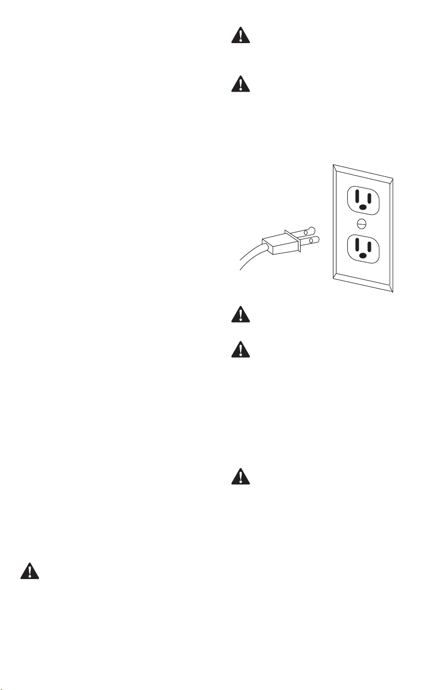
WARNING: To reduce the risk of electrical shock,
double-insulated tools are equipped with a
polarized plug (one blade is wider than the
other). This plug will t into a polarized outlet
only one way. If the plug does not t, contact a
qualied electrician to install a polarized outlet. Do not
change the plug in any way.
WARNING: Double insulation does not take the place
of normal safety precautions when operating this tool.
WARNING: Do not touch the plug blades when
inserting or removing the plug from an outlet.
CAUTION: Servicing of a product with double
insulation requires extreme care and knowledge of
the system and should be performed only by a
qualied service technician. For service, we suggest
you return the tool to your nearest authorized service
center for repair. Always use original factory
replacement parts when servicing. Do not use power
tools in wet or damp locations or expose them to rain
or snow.
ELECTRICAL CONNECTION
DOUBLE INSULATION
Double insulation is a concept in safety in electric power tools,
which eliminates the need for the usual three-wire grounded
power cord. All exposed metal parts are isolated from the
internal metal motor components with protecting insulation.
Double insulated tools do not need to be grounded.
This tool has a precision-built electric motor. It should be
connected to a power supply that is 120 volts, 60 Hz, AC only
(normal household current). Do not operate this product on
direct current (DC). A substantial voltage drop will cause a loss
of power and the motor will overheat. If the tool does not
operate when plugged into an outlet, double check the power
supply.
• AVOID KICKBACKS (work thrown back toward you) by:
a) Keeping blade sharp.
b) Keeping rip fence parallel to the saw blade.
c) Keeping spreader, anti-kickback pawls, and blade guard
in place and operating.
d) Not releasing the work before it is pushed all the way
past the saw blade using a push stick.
e) Not ripping work that is twisted or warped or does not
have a straight edge to guide along the fence.
f) When bevel ripcut, make sure the rip fence is on the right
side of the blade.
• NEVER CUT METALS, CEMENT BOARD, OR MASONRY.
These materials need to be cut by other special tools.
Cutting them with this tool can result in damage to the
saw and personal injury.
• IF THE POWER SUPPLY CORD IS DAMAGED, it must be
replaced only by the manufacturer or by an authorized
service center to avoid risk.
• AVOID AWKWARD OPERATIONS AND HAND POSITIONS
where a sudden slip could cause your hand to move into
the cutting tool.
• MAKE SURE THE WORK AREA HAS AMPLE LIGHTING to see
the work and that no obstructions will interfere with safe
operation BEFORE performing any work using the table
saw.
• If this saw makes an unfamiliar noise or if it vibrates
excessively, cease operating immediately, turn unit o and
unplug the tool until the problem has been located and
corrected. Contact a CRAFTSMAN factory service center, a
CRAFTSMAN authorized service center or other qualied
service personnel if the problem can not be found.
• Never leave the POWER TOOL unattended without rst
unplugging the power cord.
• When the tool is in maintenance or servicing or not in use,
ALWAYS turn o saw and unplug the saw. The saw will
automatically shut down when in a power failure, restart
the machine by pressing the green "I" button on the on/o
switch.
• ADDITIONAL INFORMATION regarding the safe and
proper operation of power tools (i.e., a safety video) is
available from the Power Tool Institute, 1300 Sumner
Avenue, Cleveland, OH 44115-2651
(www.powertoolinstitute.com). Information is also
available from the National Safety Council, 1121 Spring
Lake Drive, Itasca, IL 60143-3201. Please refer to the U.S.
Department of Labor OSHA 1910.213 Regulations.
• SAVE THESE INSTRUCTIONS. Refer to them frequently and
use to instruct other users. If you loan someone this tool,
loan them these instructions also.
GUIDELINES FOR EXTENSION CORDS
Use a proper extension cord. Make sure extension cords are in
good condition. When using an extension cord, be sure to use
a cord that is heavy enough to carry the drawn current needed
by the saw. An undersized cord will cause a drop in line
voltage, resulting in loss of power and overheating.
Fig. 2

ENGLISH
9
WARNING: To avoid electrical hazards, re hazards,
or damage to the tool, use proper circuit protection.
WARNING: Do not use blades rated less than the
speed of this tool. Failure to heed this warning could
result in personal injury.
WARNING: Be careful when changing the blade.
Blades are sharp. Wear work gloves when removing
or installing the blade.
WARNING: Keep the extension cord clear of the
working area. position the cord so that it will not get
caught on lumber, tools, or other obstructions while
you are working with a power tool. Failure to do so
can result in serious personal injury.
WARNING: Check extension cords before each use. If
damaged, replace immediately. Never use tool with a
damaged cord since touching the damaged area
could cause electrical shock resulting in serious injury.
Blade: For maximum performance, it is recommended that
you use the 10 in. (254 mm) carbide tipped combination blade
provided with your saw. The blade is raised and lowered with
the height/bevel adjusting handwheel. Bevel angles are locked
with the bevel locking lever. Additional blade styles of the same
high quality are available for specic operations such as ripping.
Your local dealer can provide you with complete information.
Blade kerf width must be within the limits stamped on the
riving knife.
GLOSSARY OF TERMS
The safe use of this product requires an understanding of the
information on the tool and in this operator’s manual as well
as a knowledge of the project you are attempting. Before use of
this product, familiarize yourself with all operating features and
safety rules.
Anti-kickback Pawls: Kickback is a hazard in which the
workpiece is thrown back toward the operator. The teeth on
the anti-kickback pawls point away from the workpiece. If the
workpiece should be pulled back toward the operator, the teeth
dig into the wood to help prevent or reduce the possibility of
kickback.
Bevel Scale: The easy-to-read scale on the front of the cabinet
shows the exact blade angle.
Blade Guard: Always keep the guard down over the blade for
through-sawing cuts.
Bevel Locking Lever: This lever under the worktable surface
on the front of the cabinet, locks the angle setting of the blade.
Height/Bevel Adjusting Handwheel: Located on the front
of the cabinet, this handwheel is used to lower and raise the
blade for adjustments or blade replacement. The handwheel
also makes the adjustment for bevel angles easy.
Miter Gauge: The miter gauge aligns the wood for a cross cut.
The easy-to-read indicator shows the exact angle for a miter
cut.
Miter Gauge Grooves: The miter gauge rides in these grooves
in the table on either side of the blade.
Scale: Located on the front rail, the easy-to-read scale provides
precise measurements for rip cuts.
Riving Knife: A metal piece, slightly thinner than the saw
blade, which helps keep the kerf open and prevent kickback.
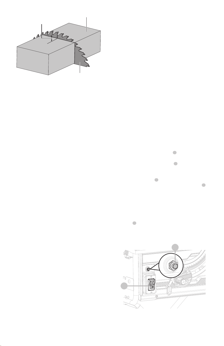
Overload Reset Switch: The saw is equipped with the
overload reset switch to prevent the saw from overload
damage. The saw will automatically shut o if the machine
was with overloaded cutting or low voltage. Wait for the motor
to cool down for at least ve minutes. And press the overload
reset switch button to resume the overload switch. After the
motor has cooled down, press the green “I”-button on the
ON/OFF switch to restart saw.
Arbor: The shaft on which a blade or cutting tool is mounted.
Working table: Surface where the workpiece rests while
performing a cutting operation.
Kerf: The material removed by the blade in a through-cut, or
the slot produced by the blade in a non-through or partial cut.
Push Stick: A push stick should be used for narrow ripping
operations when work piece 6 in. (152 mm) wide or less. These
aids help to keep the operator’s hands well away from the
blade.
Kickback: A hazard that can occur when the blade binds or
stalls, throwing the workpiece back toward the operator.
Ripping or Rip Cut: A cutting operation along the length of
the workpiece.
Bevel Cut: A cutting operation made with the blade at any
angle other than 90° to the table surface.
Be sure extension cords are properly wired and in good
condition. Always replace a damaged extension cord or have
it repaired by a qualied technician before using it. Protect
extension cords from sharp objects, excessive heat, and damp
or wet areas.
Use a separate electrical circuit for power tools. This circuit
must not be less than #14 wire with a 15 Amp time-delayed
fuse, and should be protected with a time-delayed circuit
breaker or fuse. Before connecting the tool to the power line,
make sure the switch is in the OFF position and the electric
current is rated the same as the current stamped on the
motor’s nameplate. Running at a lower voltage will damage
the motor.
The table below shows the correct size to use, depending on
the cord length and nameplate amperage rating. If in doubt,
use the next heavier gauge. The smaller the gauge number,
the heavier the cord.
MINIMUM GAUGE FOR CORD SETS
Total Length of Cord in Feet (Meter)
0 - 25
(0 - 7.6)
26 - 50
(7.9 - 15.2)
51 - 100
(15.5 - 30.5)
101 - 150
(30.8 - 45.7)
AWRating
Not More
Than
Ampere
More
Than
0 - 6
6 - 10
10 - 12
12 - 16
18
18
16
14
16
16
16
12
16
14
14
Not Recommended
14
12
12
0
01
1
2
3
4
5
6
7
8
9
10
2
3
4
5
6
7
8
9
10
11
12
10
ENGLISH
A
D
G
F
E
B
C
WARNING: Never perform any cut freehand with this
saw.
SPECIFICATIONS
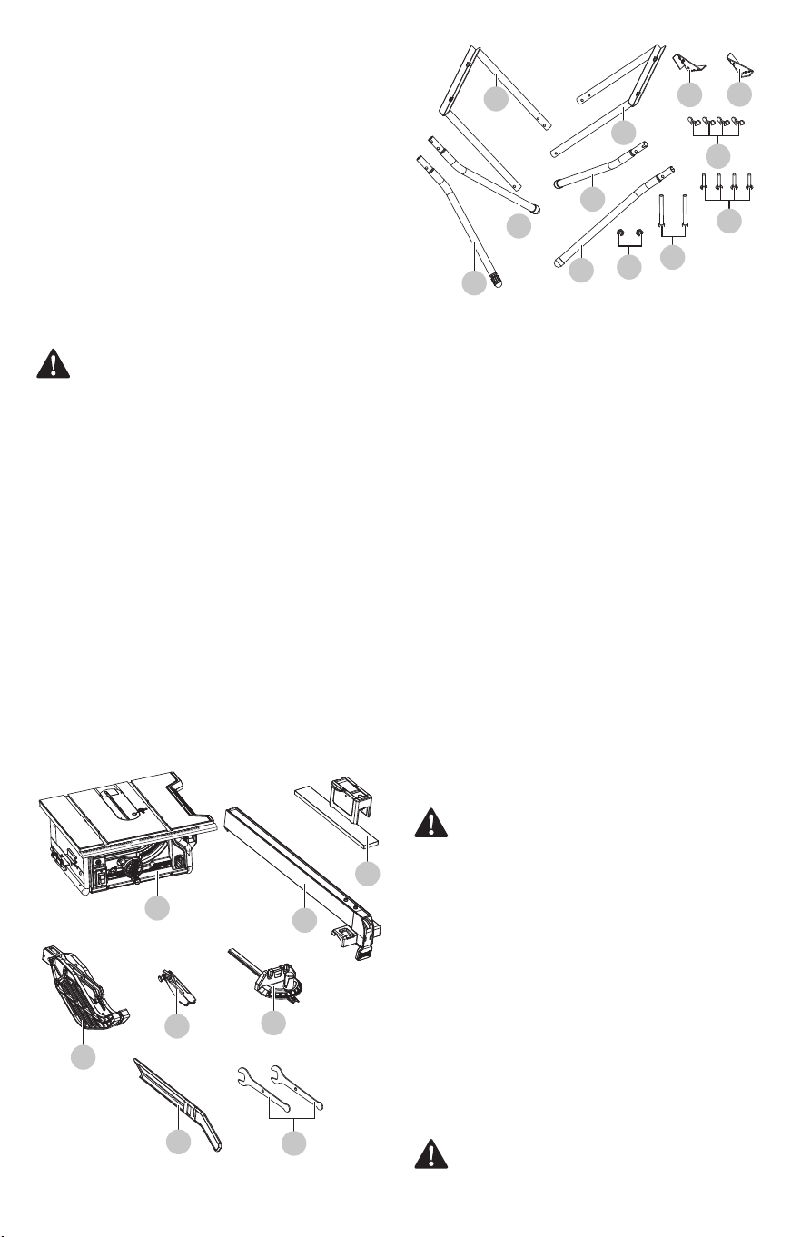
LOOSE PARTS
Motor...........................................................
Blade size.....................................................
Blade tilting range.......................................
Max. cutting capacity..................................
Table size.....................................................
Right rip capacity.........................................
Left rip capacity...........................................
Dado capacity..............................................
Weight.........................................................
120 V~ 60Hz, 15A, 5000RPM
10" x 5/8" (254 x 15.9 mm), 24T
0-45°
3 1/8" (79 mm) (90°)
2 1/4" (57 mm) (45°)
27 3/8" x 21 7/8" (695.5 x 556 mm)
12" (305 mm)
10" (254 mm)
1/2" (12.7 mm)
52 lbs (23.7 kg)
A. Table saw assemby.......................................................................................
B. Rip fence........................................................................................................
C. Sub fence assembly.......................................................................................
D. Blade guard...................................................................................................
E. Anti-kickback pawls.....................................................................................
F. Miter gauge...................................................................................................
G. Push stick......................................................................................................
H. Blade wrenches............................................................................................
I. Outer upper leg..............................................................................................
J. Inner upper leg..............................................................................................
K. Front angle plate...........................................................................................
L. Back angle plate............................................................................................
M. Lower legs....................................................................................................
N. Wing nuts......................................................................................................
O. Carriage bolts................................................................................................
P. Hex locking nuts............................................................................................
Q. Leg bolts........................................................................................................
1
1
1
1
1
1
1
2
1
1
1
1
4
4
4
2
2
The following items are included with your table saw:
CAUTION: This tool is heavy. To avoid back injury, lift
with your legs, not your back, and get help when
needed. Grasp the left and right sides of the work
table when transporting the saw.
WARNING: Remove the protective polyfoam from
between the saw’s housing and the motor.
Unpacking your table saw
ASSEMBLY
This product requires assembly.
• Carefully lift saw from the carton and place it on a level
work surface.
• Inspect the tool carefully to make sure that no breakage
or damage occurred during shipping.
• Do not discard the packing material until you have
carefully inspected and satisfactorily operated the tool.
• The saw is factory set for accurate cutting. After
assembling it, check for accuracy. If shipping has
inuenced the settings, refer to specic procedures
explained in this Operator’s Manual.
• If any part is missing or damaged, do not attempt to
assemble the table saw, plug in the power cord, or turn
the switch ON until the missing or damaged part is
obtained and is installed correctly.
Compound Cut: A crosscut made with both a miter angle and
a bevel angle.
Crosscut: A cutting or shaping operation made across the
grain or width of the workpiece.
Miter Cut: A cutting operation made with the workpiece at
any angle other than 90° to the blade.
Non-Through Cut: Any cutting operation where the blade
does not extend completely through the thickness of the
workpiece.
Through-sawing: Any cutting operation where the blade
extends completely through the thickness of the workpiece.
Dado Cut: A non-through cut which produces a square-sided
notch or trough in the workpiece (requires a special blade).
Freehand: Performing a cut without the workpiece being
guided by a fence, miter gauge, or other aid.
Fig. 3
H
M
M
L
M
M
I
J
K
N
O
Q
P
ENGLISH
11
1
2
2
3
2
2
You will need
Items not supplied:
Phillips screwdriver
13mm wrench or adjustment wrench
Framing square
Triangle square
Ruler
2.5 mm, 4 mm, 5 mm Hex key
C-Clamps
Mounting holes
The table saw must be mounted to a rm supporting surface
such as a workbench or leg stand. Four bolt holes have been
provided in the saw’s frame for this purpose.
To mount the saw to a work bench, insert bolts that are of
sucient length to accommodate the saw base, lock
washers, hex nuts, and the thickness of the workbench or
other mounting surface. Tighten all bolts or screws securely.
Carefully check the workbench after mounting to make sure
that no movement can occur during use. If any tipping,
sliding, or walking is noted, secure the workbench to the
oor before operating.
To mount the saw to the leg stand, refer to specic
procedures explained later in this section.
Items supplied:
Blade wrench (2 pc)
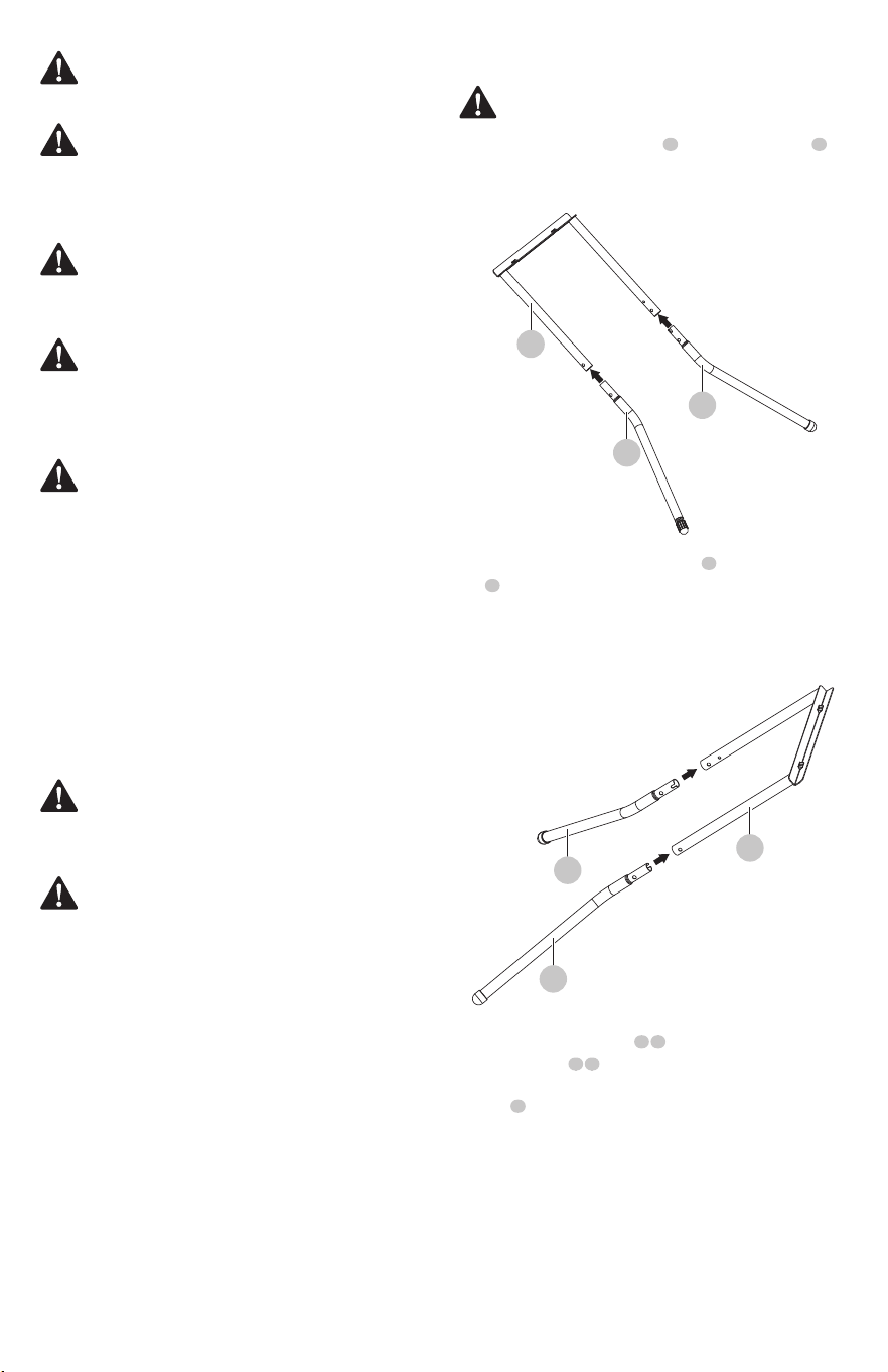
• Firmly insert two lower legs into outer upper leg .
Align the holes on the lower legs with holes on the
outer upper leg.
Fig. 4a
• Firmly insert two other lower legs into inner upper leg
. Align the holes on the lower legs with holes on the
inner upper leg.
Fig. 4b
WARNING: The use of attachments or accessories
not listed in this manual might be hazardous and
could cause serious personal injury.
WARNING: Do not use this leg stand with other
equipment or for other purposes.
WARNING: Do not attempt to modify this tool or
create accessories not recommended for use with this
tool. Any such alteration or modication is misuse,
and could result in a hazardous condition leading to
possible serious personal injury.
WARNING: Always make sure the table saw is
securely mounted to a workbench or an approved
leg stand. Never operate the saw on the oor. Failure
to heed this warning can result in serious personal
injury.
WARNING: Never stand directly in line with the blade
or allow hands to come closer than 3 in. to the blade.
Do not reach over or across the blade. Failure to heed
this warning can result in serious personal injury.
WARNING: To avoid injury, do not connect this table
saw to a power source until it is completely assembled
and adjusted and you have read and understood the
operator’s manual.
WARNING: Many of the illustrations in this manual
show only portions of the table saw. This is intentional
so that we can clearly show points being made in the
illustrations. Never operate the saw without all guards
securely in place and in good operating condition.
WARNING: Do not connect to the power supply until
assembly is complete. Failure to comply could result in
accidental starting and possible serious personal
injury.
Assembly the stand (Fig. 4a-4f)
1
1
• Lay outer leg assembly on a at surface. Place inner
leg assembly on top of outer leg assembly with
the top rails facing each other. Angled ends of lower
legs should face away from each other so they
resemble a “V”.
1 2
2
2 3
3
2
12
ENGLISH
2
5
6
7
7
6
2
2
4
3
2
1
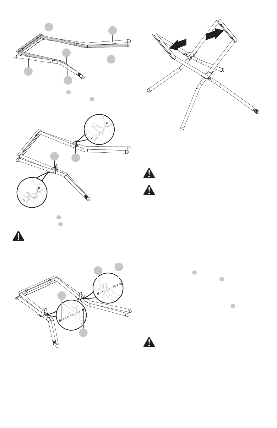
• Place front angle plate between leg assembly on right
side. Repeat with back angle plate on left side.
Carefully align holes in legs and angle plate.
CAUTION: DO NOT overtighten. Stand should fold
and unfold smoothly.
WARNING: Do not t the saw without help. The saw
is heavy. Hold it close to your body. Keep your knees
bent and lift with your legs, not your back. Ignoring
these precautions can result in back injury.
WARNING: Lower the blade to lowest position before
mounting saw.
WARNING: Ensure all four bolts are present and
properly fastened. Do not use saw if any bolts are
missing or damaged. If missing or damaged, Call
1-888-331-4569 for replacement hardware.
NOTICE: When positioning stand, make sure each leg is
spread fully outward to ensure stability.
NOTICE: Turning clockwise will lower leveling foot. Turning
counterclockwise will raise leveling foot.
NOTICE: Make sure the table saw’s frame is ush against the
stand and that all the legs are touching the ground.
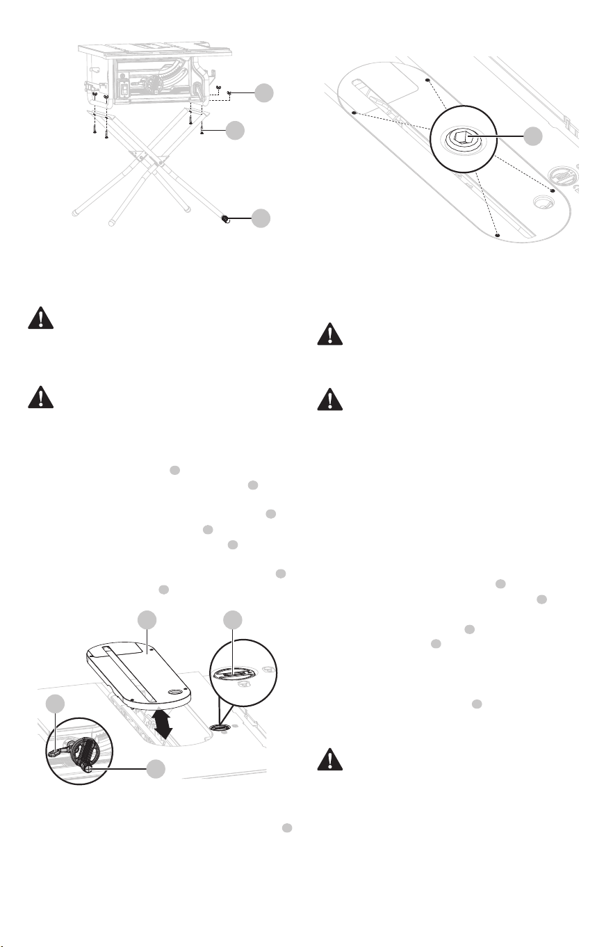
Mounting the table saw to the stand
(Fig. 5)
• Position the table saw onto the stand so that holes in
the saw’s frame are aligned with the holes in the stand’s
brackets.
• Install carriage bolts through the holes in the brackets
and frame. Secure with wing nuts and tighten
securely.
• Be sure the table saw is on level ground and the stand is
sturdy before use.
• If the saw wobbles, adjust leveling foot until stand is
balanced.
Fig. 4d
Fig. 4e
Fig. 4c Fig. 4f
4
6
7
1
2
3
5
• Install stand bolts through holes and tighten stand
bolts and hex nuts securely.
• Place the stand on level ground and open to its fully
extended position.
0
01
1
2
3
4
5
6
7
8
9
10
2
3
4
5
6
7
8
9
10
11
12
ENGLISH
13
4 3
2
2
5
1
1
3
• Lower the blade all the way to down position by turning
the height adjusting handle counter-clockwise.
• Lock the blade by turning bevel locking lever
clockwise.
• To remove the table insert: Turn the lock knob
clockwise to unlock the table insert . Place your index
nger in the hole, pulling the table insert out toward
the front of the saw.
• To reinstall the table insert: Push the table insert
down, turn the lock knob counter-clockwise to lock
the table insert in place.
If the table insert is not level with the saw table, using a
2.5 mm hex key (not supplied), adjust the four set screws
pre-assembled to the table located on the four holes of the
table insert until the table insert is level with the working
table.
WARNING: The table insert must be level with the
saw table. If the table insert is too high or too low, the
workpiece can catch on the uneven edges, resulting in
binding or kickback, which could result in serious
personal injury.
WARNING: Be extremely careful your hands, avoid
to contact with the saw blade which can result in
serious personal injury when removing or replacing
the table insert.
CAUTION: This saw is shipped with riving knife in
“MIDDLE” position. Riving knife must be placed in
uppermost position to attach anti-kickback pawls
and blade guard for all through cut operations.
WARNING: Riving knife has three holes for three
positions. The uppermost position is for all through
cuts. The middle position is for non-through cuts (with
blade guard and anti-kickback pawls removed). The
down position is for dado cuts. (with blade guard and
anti-kickback pawls removed).
WARNING: Be extremely careful when adjusting the
riving knife position. Do not contact blade.
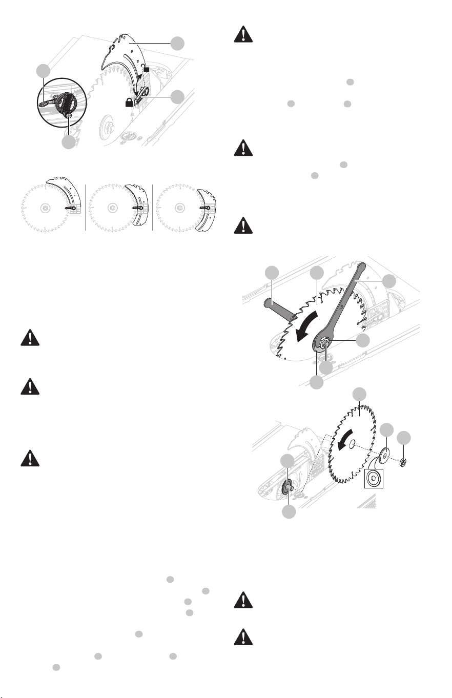
Riving knife installation and position
(Fig.7a-7b)
To remove/replace/align the table insert
(Fig. 6a-6b)
• Turn saw off and unplug saw.
• Remove the table insert.
• Set the saw blade angle to 0°.
• Raise the saw blade to the uppermost position by
turning the height adjusting handle clockwise.
• Lock the blade by turning bevel locking lever
clockwise.
• Unlock riving knife lock knob by turning it clockwise.
• Grasp the riving knife and pull toward right side of
saw to release it from spring-loaded locking pin.
• Position the riving knife in the uppermost position with
spring-loaded locking pin re-engaged.
• Lock the riving knife lock knob by turning it counter-
clockwise.
• Reinstall the table insert.
To place riving knife in uppermost position (for
through cuts)
Fig. 6a
Fig. 6b
Fig. 5
1
2
4
4
4
1
2
3
3
4
3
3
5
14
ENGLISH
• Using one opened-ended blade wrench , place the
at open end on the ats on the inner blade ange .
• Using the other opened-ended blade wrench , place
the at open end on the ats on the arbor nut .
Holding both wrenches rmly, pull the opened-ended
blade wrench on the arbor nut forward to the front of
the machine.
• Remove arbor nut , outer blade ange and saw
blade .
1
2
1
5
7
7
6
6
2
5
4
4
4
3
3
In uppermost position
for through cuts
In middle position
for non-through cuts
In down position
for dado cuts
CAUTION: To work properly, the saw blade teeth
must point down toward the front of the saw. Failure
to heed this instruction could cause damage to the
saw blade, the saw or the workpiece.
WARNING: Make sure that the saw blade is installed
to rotate in the proper direction. Do not use grinding
wheels, wire brushes, or abrasive wheels on a table
saw. Improper saw blade installation or use of
accessories not recommended may cause serious
injury.
WARNING: Only use a 10 in. diameter blade. To avoid
injury from an accidental start, make sure the switch
is in the OFF position .
Removing and installing the blade
(Fig. 8a-8b)
Remove the blade:
• Place one new blade on arbor . Make sure saw blade
teeth point down at the front side of saw table. Place
outer ange and arbor nut on arbor and use
blade wrenches to tighten arbor nut securely. DO NOT
over tighten.
• Lower the saw blade to lowest position and replace
table insert.
Install the blade:
To place riving knife in middle or down position, refer
to the above procedure.
Fig. 7a
Fig. 7b
WARNING: Be extremely careful when loosening
arbor nut. Keep rm grasp on both wrenches. Do
not allow hands to slip and contact blade.
WARNING: If the inner ange has been removed,
reinstall it before placing the saw blade on arbor.
Failure to do so could cause an accident.
CAUTION: Ensure the large, at surface (cupped side
of the outer ange) of the outer ange faces the saw
blade and the saw blade is rmly seated against
the inner ange .
WARNING: Make sure the anti-kickback pawls are
reinstalled immediately after nishing any non-
through cut operations which require their removal.
WARNING: Replace dull or damaged anti-kickback
pawls. Dull or damaged anti-kickback pawls may not
stop a kickback, increasing the risk of serious personal
injury.
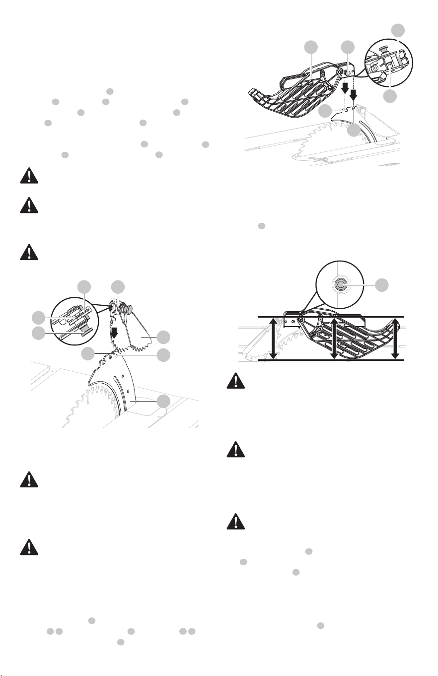
Anti-kickback pawls installation (Fig. 9)
Anti-kickback pawls should only be installed for through
cuts.
Fig. 8a
Fig. 8b
1
4
4
5
5
6
6
2
7
4
4
3
2
• Turn saw off and unplug saw.
• Lower the saw blade and remove the table insert.
• Make sure the bevel locking lever is securely locked.
Turn height adjustment knob clockwise to raise blade to
maximum height.
• Place riving knife in the uppermost position.
• Remove the blade wrenches from storage area.
ENGLISH
15
5 5
8
2
3
6
1
7
4
CAUTION: Pull up on anti-kickback pawls assembly
to make sure it is secured to riving knife.
• Turn saw off and unplug saw.
• Set the blade angle to 0°.
• Raise the saw blade to maximum height by turning
height adjustment handle clockwise.
• Lock the blade by turning bevel locking lever clockwise.
• Place the riving knife in the uppermost position.
• Pull out and hold knob . Align slot in anti-kickback
pawls over the slot marked of riving knife . Place
the spring pin on the anti-kickback pawls into the
slot marked on the riving knife .
• Press on anti-kickback pawls assembly down until it
snaps into place and release knob to insert the pin
into hole marked on the riving knife .
Fig. 10b
1
1
2
5
6
7
2
3
3
4
4
4
3
5
4 1
2
6
WARNING: Gently pull up the anti-kickback pawls
assembly to ensure it is locked into place. Make sure
that the anti-kickback pawls move freely and are not
stuck in the table insert slot.
WARNING: Use extra caution when cutting wood
products having slippery surfaces as the anti-kickback
pawls may not always be eective.
WARNING: KEEP GUARDS IN PLACE and in good
working order for all through cut operations. Reinstall
the blade guard immediately after nishing any non-
through cut operations which require removal of the
blade guard. Failure to heed this instruction could
result in serious personal injury.
WARNING: Always install the blade guard onto the
riving knife in the uppermost position to provide
proper blade coverage. Installing the blade guard
onto the riving knife in any other position will prevent
them from working as designed, which could increase
the risk of serious personal injury.
WARNING: To reduce the risk of injury, always make
sure the rip fence is parallel to the blade before
beginning any operation.
WARNING: When using the blade guard, lift the left
and right blade guard and make sure that they move
independently and contact the table surface. The
blade guard can be raised to adjust the cut line, but
must be lowered to contact the table surface before
starting the saw.
WARNING: Make sure blade guard and anti-kickback
pawls move freely before starting the saw. Ensure the
direction of rotation by verifying that the blade teeth
point down toward the front of the saw table.
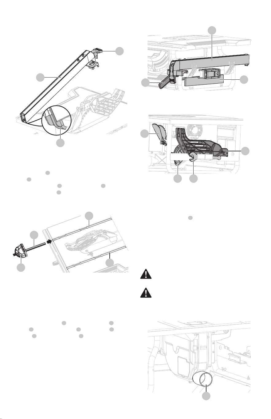
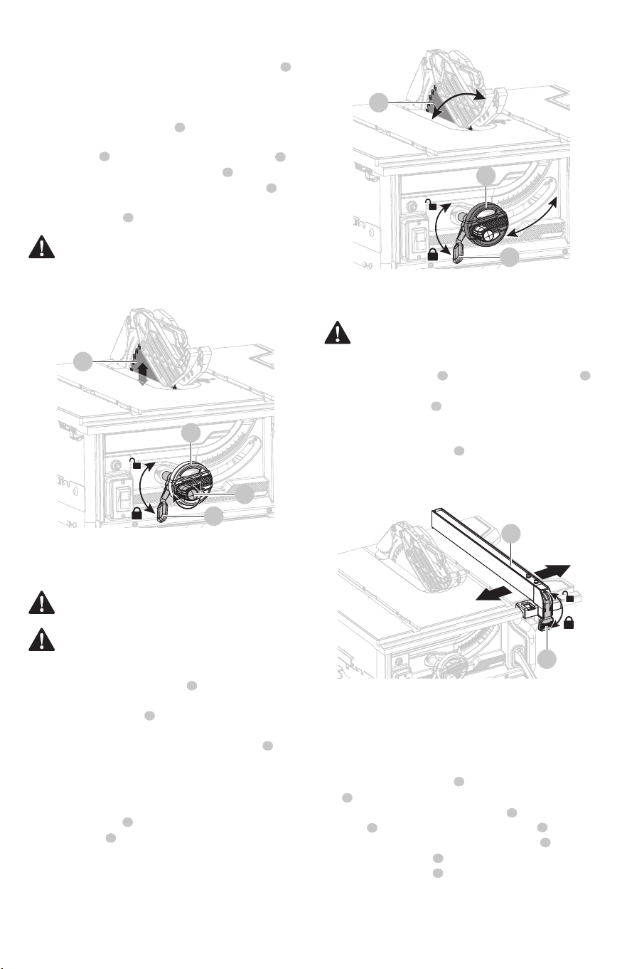
Rip fence installation (Fig. 11)
Blade guard installation (Fig. 10a-10b)
• Loosen the rip fence by lifting up the locking handle
.
• Place the rear lip on the rear of the saw table and pull
slightly toward the front of the unit.
• Lower the front end of the rip fence onto the guide
surfaces on top of the front rail.
• Check for smooth gliding action.
• Push the locking handle down and secure the fence.
When securely locked, the locking lever should point
downward.
• Pull blade guard fully back onto riving knife. Push pin
and release it to lock guard into position.
• If blade guard is not parallel to table when riving knife is
in uppermost position (through cuts), adjust the set
screw with 2.5 mm hex key (not supplied) as
necessary. (Fig. 10b)
Fig. 9
Fig. 10a
1
3
2
2
8
• Turn saw off and unplug saw.
• Pull out the knob on the blade guard and place the
pins on the blade guard into the slots
marked on the riving knife .
1
2 3 5 6
7
4
0 1 2 3
4
5
6
7
8
9
10
11
12
0
01
1
2
3
4
5
6
7
8
9
10
2
3
4
5
6
7
8
9 10 11 12
16
ENGLISH
2
3
4
2
1
75
3
6
Miter gauge installation (Fig. 12)
The miter gauge can be installed on each miter gauge
groove on either side of blade.
• Slide the guide rail of the miter gauge into one of
the guide grooves of the saw table intended for this
purpose.
NOTICE: Care should be taken to position hoses to not
interfere with cutting operation.
Connect to a dust collection system
(Fig. 14)
The dust extraction port with a standard 2 1/2" (63.5mm)
diameter is located on the rear of the table saw. This port
can be connected directly to a dust collection system by
connecting the pick up end of the dust collection hose to
the dust port.
Fig. 13a
Fig. 13b
Fig. 14
1
2
To store the table saw accessories
(Fig. 13a-13b)
• The table saw has two convenient storage areas (one on
either side of the saw) specically designed for the saw’s
accessories: rip fence , sub fence assembly , push
stick , anti-kickback pawls , miter gauge , blade
guard and blade wrenches .
• When not in use, unplug the saw and store accessories
securely.
1 2
3 4 5
6 7
3
2
1
1
2
1
1
2
1
3
Ensure the locking handle secures the rip fence in place. If
adjustment are needed, see “To check the tightness of the
rip fence locking handle” in the adjustment section.
Fig. 11
Fig. 12
CAUTION: It is strongly recommended to connect a
dust collection system to the dust extraction port.
WARNING: Table saw must be regularly checked for
dust built up and cleaned frequently, otherwise there
is a risk of heat built up and potential re.

ENGLISH
17
WARNING: To reduce the risk of serious personal
injury, turn unit o and unplug the tool before making
any adjustments or removing/installing attachments
or accessories. An accidental start-up can cause injury.
WARNING: Before using the saw, verify the following
each and every time:
• ALWAYS wear proper eye, hearing and respiratory
equipment.
• Blade is securely tightened.
• Bevel locking lever is locked.
• If ripping, ensure that rip fence locking handle is
locked and that the fence is parallel to the blade.
• If crosscutting, miter gauge lock knob is securely
tightened.
• The blade guard assembly is properly attached
and the anti-kickback assembly is functioning.
• Have push sticks available and accessible.
OPERATION
WARNING: To reduce the risk of serious personal
injury, have push stick ready to use before starting
cut.
WARNING: Feed the workpiece into the saw blade
only against the direction of rotation. Feeding the
workpiece in the same direction that the saw blade is
rotating above the table may result in the workpiece,
and your hand, being pulled into the saw blade.
WARNING: When the tool is in maintenance or
servicing or not in use, ALWAYS turn o saw and
unplug the saw. The saw will automatically shut
down when in a power failure, restart the machine by
pressing the green "I" button on the on/o switch.
WARNING: ALWAYS make sure your workpiece is not
in contact with the blade before operating the switch
to start the saw. Blade contact could result in kickback
or thrown workpiece.
WARNING: To reduce the risk of accidental starting,
ALWAYS make sure the switch is in the OFF position
before plugging saw into the power source.
WARNING: DO NOT use blades rated less than the
speed of this tool. Failure to heed this warning could
result in serious personal injury.
WARNING: Never operate the saw with the blade
guard removed except for dado and other non-
through cuts. Reinstall the blade guard immediately
after nishing any non-through cut operations which
require removal of the blade guard. Failure to heed
this instruction could result in serious personal injury.
WARNING: The operation of any power tool can
result in foreign objects being thrown into the eyes,
which can result in severe eye damage. Always wear
safety goggles or standard safety glasses with side
shields complying with United States ANSI Z87.1
before commencing power tool operation.
Operating components
• The upper portion of the blade projects up through the
table and is surrounded by an insert called the table
insert. The height of the blade is set with a height
adjusting handle on the height/bevel adjusting
handwheel. Detailed instructions are provided in this
manual for the basic cut: cross cuts, miter cuts, bevel
cuts, and compound cuts.
• The rip fence is used to position workpiece for
lengthwise cuts.
• It’s very important to use the riving knife, anti-kickback
pawls, and blade guard for all through-cut sawing
operations.
Causes of kickback
Kickback can occur when the blade stalls or binds, causing
the workpiece to be kicked back toward the operator with
great force and speed. If your hands are near the saw blade,
they may be jerked loose from the workpiece and come into
contact with the blade. Obviously, kickback can cause
serious injury, and it is well worth using precautions to avoid
the risks. Kickback can be caused by any action that pinches
the blade in the wood, such as the following:
• Making a cut with incorrect blade depth.
• Sawing into knots or nails in the work piece.
• Twisting the wood while making a cut.
• Failing to support the workpiece.
• Forcing a cut.
• Cutting warped or wet lumber.
• Using the wrong blade for the type of cut.
• Not following correct operating procedures.
• Misusing the saw.
• Failing to use the anti-kickback pawls.
• Cutting with a dull, gummed-up, or improperly set
blade.
Avoiding kickback
NOTICE: Kickback can be avoided by taking following
proper precautions:
• Always use the correct blade depth setting. The top of
the blade teeth should clear the workpiece by 1/8 in.
(3 mm) to 1/4 in. (6 mm). (See Fig. 15)
Applications
You can use this tool for the purposes listed below:
• Straight-line cutting operations, such as crosscutting,
ripping, mitering, and compound cutting.
• Dado with optional accessories.
NOTICE: This table saw is designed to cut wood and wood
composition products only. Never cut metals, cement
board, or masonry.
18
ENGLISH
• The product can be switched on by pressing the green
“I”-Button on the on/o switch .
• The product can be switched off by pressing the red
“0”-Button on the on/o switch .
• The saw will automatically shut down when in a power
failure, restart the machine by pressing the green "I" button
on the on/o switch .
• The saw is equipped with the overload reset switch to
prevent the saw from overload damage. The saw will
automatically shut o if the machine was with overloaded
cutting or low voltage. Wait for the motor to cool down for
at least ve minutes. And press the overload reset switch
button to resume the overload switch. After the motor has
cooled down, press the green “I”-button on the ON/OFF
switch to restart saw.
into the saw blade.
• Never hold and press the workpiece that is being cut
o against the rotating saw blade. Pressing the
workpiece being cut o against the saw blade will
create a binding condition and kickback.
• Use of a featherboard will help hold the workpiece
securely against the saw table or fence when making
non-through cuts such as rabbets, dado cuts. A
featherboard helps to control the workpiece in the
event of a kickback.
• Never cut more than one workpiece, stacked vertically
or horizontally. The saw blade could pick up one or
more pieces and cause kickback.
• Clean the saw, blade guard, under the table insert, and
any areas where saw dust or scrap workpieces may
gather.
• Use the right type of blade for the cut being made.
• Always use the riving knife for every operation where it
is allowed. The use of this device will greatly reduce the
risk of kickback.
1
2
On/O switch and overload reset button
(Fig. 16)
Fig. 16
Fig. 15
1
1
1
1
2
• Inspect the work for knots or nails before beginning a
cut. Knock out any loose knots with a hammer. Never
saw into a loose knot or nail.
• Always use the rip fence when rip cutting. Use the miter
gauge when cross cutting. This helps prevent twisting
the wood in the cut.
• Align the fence to be parallel with the saw blade. A
misaligned fence will pinch the workpiece against the
saw blade and create kickback.
• Always use a clean, sharp, and properly set blade. Never
make cuts with a dull blade. Never use a warped saw
blade or saw blade with cracked or broken teeth.
Sharp and properly set saw blade minimize binding,
stalling and kickback.
• To avoid pinching the blade, support the workpiece
properly before beginning a cut.
• Support large panels to minimize the risk of saw blade
pinching and kickback. Large panels tend to sag under
their own weight. Support(s) must be placed under all
portions of the panel overhanging the table top.
• When making a cut, use steady, even pressure. Never
force cuts.
• Do not cut wet or warped lumber.
• Use extra caution when cutting some prenished or
composition wood products as the anti-kickback pawls
may not always be eective.
• Use extra caution when making a cut into blind areas of
assembled workpieces. The protruding saw blade may
cut objects that can cause kickback.
• Use extra caution when cutting a workpiece that is
twisted, knotted, warped or does not have a straight
edge to guide it with a miter gauge or along the fence.
A warped, knotted, or twisted workpiece is unstable and
causes misalignment of the kerf with the saw blade,
binding and kickback.
• Always guide your workpiece with both hands or with
push sticks and/or push blocks. Keep your body in a
balanced position to be ready to resist kickback should it
occur. Never stand directly in line with the blade. Always
position your body on the same side of the saw blade as
the fence. Kickback may propel the workpiece at high
velocity towards anyone standing in front and in line
with the saw blade.
• Never reach over or in back of the saw blade to pull or
to support the workpiece. Accidental contact with the
saw blade may occur or kickback may drag your ngers
1/8” (3 mm) -1/4” (6 mm)1/8” (3 mm) -1/4” (6 mm)
1/8” (3 mm) -1/4” (6 mm)
Workpiece
Saw blade
0
01
1
2
3
4
5
6
7
8
9
10
2
3
4
5
6
7
8
9
10
11
12
0
01
1
2
3
4
5
6
7
8
9
10
2
3
4
5
6
7
8
0
01
1
2
3
4
5
6
7
8
9
10
2
3
4
5
6
7
8
ENGLISH
19
• Loosen the rip fence by lifting the locking handle
up.
• Move the rip fence to the desired distance from the
blade and ensure the rip fence is level on the working
table.
• Push the locking handle down to secure the fence.
When securely locked, the locking handle should point
downward.
When ripping a narrow workpiece, it is necessary to attach
the sub fence assembly to the rip fence to prevent hands
from getting too close to the blade.
• Pull up the locking knob on the sub fence assembly
.
• Align the slot of sub fence assembly with the rip
fence , and push the sub fence assembly down.
• Lock it in place by pushing down lock knob .
• Sub fence assembly can be mounted on left or right
side of the rip fence .
• When not in use, store the sub fence assembly in
storage position.
Use sub fence assembly (for rip cutting narrow
workpiece) (Fig. 19b)
1
3
2
4
2
3
1
1
2
Fig. 17
Fig. 18
Fig. 19a
WARNING: Make sure the blade guard is in place
after adjusting the blade depth. Failure to heed this
instruction could result in serious personal injury.
Blade depth should be set so that outer points of blade
are higher than workpiece by approximately 1/8 in. (3 mm)
to 1/4 in. (6 mm) and bottom of gullets are below top
surface of workpiece. (Fig. 15)
• Turn the bevel locking lever clockwise to tighten it
securely.
• Raise blade by turning height adjusting handle on
the height/bevel adjusting handwheel clockwise.
Lower blade by turning height adjusting handle
counter-clockwise.
• Make sure blade is at proper height.
Changing blade depth (Fig. 15, 17)
1
2
1
1
1
• Loosen the bevel locking lever counter-clockwise.
• Adjust bevel angle by rst pushing height/bevel
adjusting handwheel all the way to the left.
• Holding height/bevel adjusting handwheel, slide bevel
indicator to the right to increase angle of blade
(bringing it closer to 45° from the tabletop). Holding
height/bevel adjusting handwheel, slide bevel indicator
to the left to decreases the angle (bringing blade closer
to 90° from the tabletop).
• Make sure blade is at desired angle. Tighten bevel
locking lever clockwise.
1
1
2
3
3
1
2
1
2
2
3
3
2
1
2
2
3
4
3
WARNING: To reduce the risk of injury, always make
sure the rip fence is parallel to the blade before
beginning any operation.
Rip fence (Fig. 19a-19b)
CAUTION: A 90° cut has a 0° bevel and a 45° cut has
a 45° bevel.
CAUTION: If bevel indicator is not at zero when saw
blade is at 0°, see the section “To adjust bevel
indicator”.
Changing blade angle (bevel) (Fig. 18)
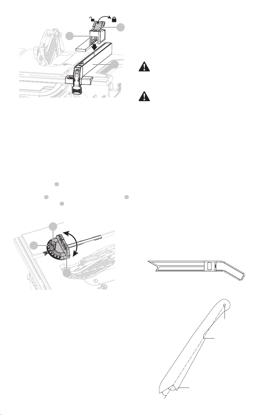
0
01
1
2
3
4
5
6
7
8
9
10
0
01
1
2
3
4
5
6
7
8
20
ENGLISH
3
3
2
1
1
2
Fig. 19b
Fig. 20
Push sticks
Push stick can be purchased or made to securely hold down
the workpiece against the table when making non-through
cuts or ripping narrow stock. The stick must be narrower
than the workpiece, with a 90° notch in one end and shaped
for a grip on the other end.
How to make an additional push stick
(Fig. 21a-21b)
• In order to operate your table saw safely, you must use a
push stick whenever the size or shape of the workpiece
would otherwise cause your hands to be within 6 in.
(152 mm) of the saw blade or other cutter. A push stick
is included with this saw (Fig. 21a).
• No special wood is needed to make additional push
sticks as long as it’s sturdy and long enough. Make sure
that a push stick is long enough and has a notch that ts
against the edge of the workpiece to prevent slipping.
It’s a good idea to have several push sticks of the same
length with dierent size notches for dierent
workpiece thicknesses.
• The shape can vary to suit your own needs as long as it
performs its intended function of keeping your hands
away from the blade.
WARNING: Use only the push stick provided by the
manufacturer or constructed in accordance with the
instructions. This push stick provides sucient
distance of the hand from the saw blade.
WARNING: Never use a damaged or cut push stick. A
damaged push stick may break causing your hand to
slip into the saw blade.
Fig. 21a
Fig. 21b
1
1
32
Miter gauge (Fig. 20)
Cutting aids such as push stick, push blocks, featherboards
and jigs should be used where appropriate to maximize
your ability to control your workpiece for a safe and precise
cut. When making non-through cuts or ripping narrow
stock, always use a push stick, push block, featherboard
and/or jig set-up so hands do not come within 6 inches of
blade.
A push stick is included with your saw. Additional push
sticks and other cutting aids can be purchased separately at
any authorized dealer. A push block has a handle fastened
by recessed screws from the underside. Use push blocks for
narrow cuts and all non-through cuts. Instructions for
making cutting aids can be found in later section.
Cutting aids
The miter gauge provides accuracy in angled cuts. For very
close tolerances, test cuts are recommended.
There are two miter gauge grooves, one on either side of
blade. When making a 90° cross cut, use either miter gauge
groove. When making a beveled cross cut (blade tilted in
relation to working table, miter gauge should be located in
groove on right so that blade is tilted away from miter
gauge and hands.
The miter gauge can be turned 60° to the left or right.
• Loosen lock knob turning it counter-clockwise.
• With miter gauge in miter gauge groove, rotate miter
gauge body until desired angle is reached on scale .
• Retighten lock knob turning it clockwise.
Additional Push Stick Construction
Included standard push stick
20°-30°
90°
Notch to
prevent hand
from slipping
Cut here to match wood
thickness when needed
Drill hole for
hanging
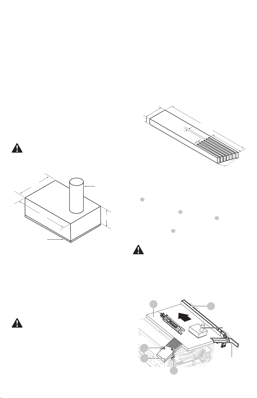
0123
4
5
6
7
8
9
10
70°
3/4 in.
(19 mm)
12 in.
(305 mm)
4 in. (100 mm)
2 1/2 in.
(63 mm)
1/4 in.
(6 mm)
1/8 in.
(3 mm)
Sandpaper or
old mouse pad
material
Wooden
dowel
4 in.
(101 mm)
6 in.
(152 mm)
2 in. (51 mm)
ENGLISH
21
How to make a push block (Fig. 22)
• Select a piece of wood about 4 in. (101 mm) wide, 6 in.
(152 mm ) long and 1 (25 mm) to 2 in. (51 mm) thick (a
cuto from a 2 in. (51 mm) by 4 in. (101 mm) makes a
good blank for a push block).
• Drill a hole in the block and glue in a dowel to use as a
handle (you can angle the hole to provide a more
comfortable grip on the handle).
• To nish off the block, glue a piece of sandpaper or
some kind of rubber material (old mouse pads work
well) to the bottom of the block.
Push blocks
How to make a featherboard (Fig. 23)
Push blocks are blocks used to securely hold down the
workpiece against the table. They include some gripping
surface or handle to hold the block. Any screws running
through the underside of the block to fasten the handle
should be recessed in order to avoid contact with the
workpiece.
WARNING: When using featherboard, it must be
mounted in front of the blade and used only against
the uncut portion of the workpiece to avoid a
kickback that could result in serious injury.
Featherboards
A featherboard is a device used to help control the
workpiece by guiding it securely against the table or rip
fence. Featherboards are especially useful when ripping
small workpieces and for completing non-through cuts. The
end is angled with a series of narrow slots to give a friction
hold on the workpiece. It is locked in place on the table with
a C-clamp. Test to ensure it can resist kickback.
• The featherboard is an excellent project for the saw.
Select a solid piece of lumber approximate 3/4 in.
(19 mm) thick, 2 1/2 in. (63 mm) wide and 12 in.
(305 mm) long.
• Mark the center width on one end of stock. Miter width
to 70° ( See miter cut section for information on miter
cuts).
• Set rip fence to allow approximately a 1/4 in. (6 mm)
“nger” to be cut in the stock.
• Feed the stock only to the mark previously made at 4 in.
(100 mm).
• Turn saw o and allow blade to completely stop
rotating before removing stock.
• Reset rip fence and cut spaced rips into workpiece to
allow approximately 1/4 in. (6 mm) ngers and 1/8 in.
(3 mm) spaces between ngers.
How to mount a featherboard (Fig. 24)
• Completely lower the saw blade. Position the rip fence
to the desired adjustment for the cut to be performed
and lock.
• Place the workpiece against the fence and over the
saw blade area. Adjust the featherboard to apply
resistance to the workpiece just forward of the blade.
Attach C-clamps (not included) to further secure the
featherboard to the edge of the saw table.
Fig. 23
Fig. 22
1
2
3
4
WARNING: Use a push block when the distance
between the fence and the saw blade is less than 2 in.
(51 mm).
1
3
4
2
4
Fig. 24
WARNING: Do not locate the featherboard to the
rear of the workpiece. If positioned improperly,
kickback can result from the featherboard pinching
the workpiece and binding the blade in the saw kerf.
Failure to heed this warning can result in serious
personal injury.
Push stick
Push block
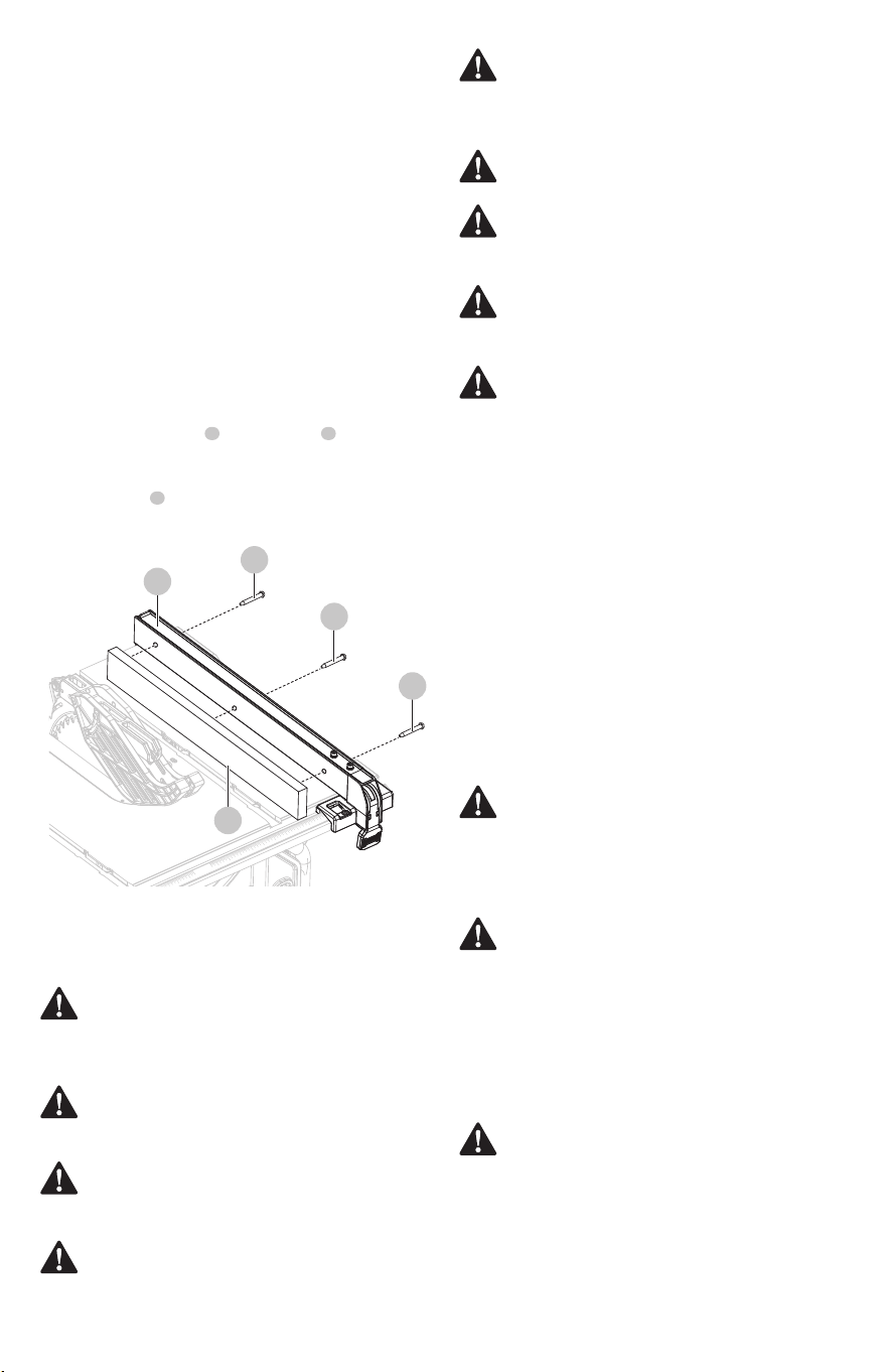
0
01
1
2
3
4
2
3
4
5
6
7
8
9
10
11 12
22
ENGLISH
• Select a piece of wood 3/4 in. (19 mm) thick, 2 3/8 in.
(60 mm) wide and as long as the rip fence.
• Drill a 1/4 in. (6 mm) hole, 1 in. (25 mm) from each end
and 1 1/8 in. (28.5 mm) from bottom of the rip fence
• Drill a 1/4 in. (6 mm) hole in the middle rip fence 1/2 in.
(12.5 mm) from bottom of rip fence.
• Attach auxiliary fence to the rip fence ; place wood
against rip fence and rmly on the working table.
• From back side of rip fence, secure wood to fence using
wood screws (not included).
Dado and rabbet cuts are non-through cuts which can be
either rip cuts or cross cuts. Carefully read and understand
all sections of this operator’s manual before attempting any
operation.
• The kerf (the cut made by the blade in the wood) will be
wider than the blade to avoid overheating or binding.
Make allowance for the kerf when measuring wood.
• Make sure the kerf is made on the waste side of the
measuring line.
• Cut the wood with the nish side up.
• Knock out loose knots before making cut.
• Always provide proper support for wood as it comes out
of saw.
1 2
3
2
1
3
3
3
Fig. 25
Auxiliary fence
An auxiliary fence is a device used to close the gap between
rip fence and working table. ALWAYS make and use an
auxiliary fence when ripping material 1/8 in. (3 mm) or
thinner to prevent stock from slipping under fence.
How to make and attach an auxiliary
fence (for rip cutting thin workpiece)
(Fig. 25)
Through cuts
Cutting tips
WARNING: Always make sure the blade guard and
anti-kickback pawls are in place and working
properly when making these cuts to avoid possible
injury.
WARNING: Use extra caution when cutting wood
products having slippery surface as the anti-kickback
pawls may not always be eective.
WARNING: DO NOT use blades rated less than the
speed of this tool. Failure to heed this warning could
result in personal injury.
WARNING: To avoid kickback, make sure one side of
the workpiece is securely against the rip fence during
any rip cut, and hold the workpiece rmly against the
miter gauge during any miter cut.
WARNING: DO NOT attempt compound miter cuts,
with blade beveled and miter fence angled, until you
are thoroughly familiar with the basic cuts and
understand how to avoid kickback.
WARNING: DO NOT attempt to make any cuts not
covered here.
WARNING: Using rip fence as a cuto gauge when
cross cutting will result in kickback which can cause
serious personal injury.
WARNING: NEVER make freehand cuts (cuts without
miter gauge or rip fence). Unguided workpieces can
result in serious injury.
WARNING: Never make through cuts without the
blade guard in place. Failure to heed this instruction
could result in serious personal injury.
WARNING: Do not use blades rated less than the
speed of this tool. Failure to heed this warning could
result in personal injury.
Making cuts
• The blade provided with the saw is a high-quality
combination blade suitable for ripping and cross cut
operations. Carefully check all setups and rotate the
blade one full revolution to assure proper clearance
WARNING: Before making any cuts, make sure that
the table saw stand is on a rm level surface where
there is plenty of room to handle and properly support
the table saw and the workpiece. If a suitable location
can not be found, then the saw should not be used.
Operating the saw in a location that does not provide
adequate space and stable footing for the table saw
stand could create a tipping hazard which could
result in serious personal injury.
WARNING: DO NOT attempt to make any cuts not
covered in this MANUAL and this tool is not permitted
for making cuts for other commercial purposes.
Failure to heed this warning will result in serious
personal injury.
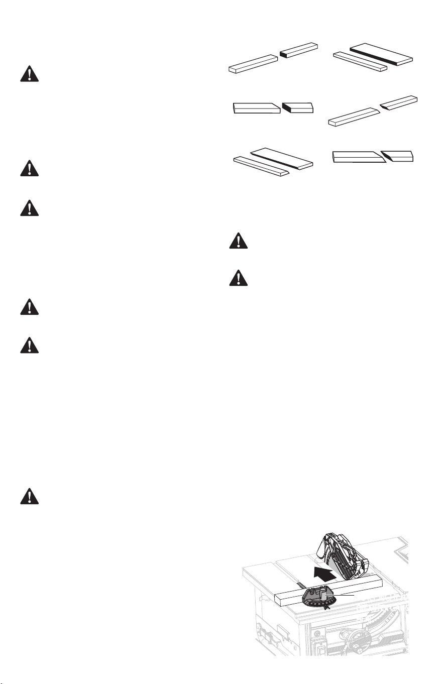
0
01
1
2
3
4
5
6
7
8
9
10
2
3
4
5
6
7
8
Cross cut
Rip cut
Miter cut
Bevel cross cut
Bevel rip cut
Compound (bevel)
miter cut
ENGLISH
23
Fig. 26
Types of cuts (Fig. 26)
There are six basic cuts: 1) the cross cut, 2) the rip cut, 3) the
miter cut, 4) the bevel cross cut, 5) the bevel rip cut, and 6)
the compound (bevel) miter cut.
Cross cuts are straight 90° cuts made across the grain of the
workpiece. The wood is fed into the cut at a 90° angle to the
blade, and the blade is vertical.
Rip cuts are made with the grain of the wood. To avoid
kickback while making a rip cut, make sure one side of the
wood rides rmly against the rip fence.
Miter cuts are made with the wood at any angle to the
blade other than 90°. The blade is vertical. Miter cuts tend to
“creep” during cutting. This can be controlled by holding
the workpiece securely against the miter gauge.
Bevel cuts are made with a blade set at an angle. Bevel
cross cuts are across the wood grain, and bevel rip cuts are
with the grain.
Compound (or bevel) miter cuts are made with a blade set
at an angle on wood that is angled to the blade. Be
thoroughly familiar with making cross cuts, rip cuts, bevel
cuts, and miter cuts before trying a compound miter cut.
• Use the miter gauge when making cross, miter, bevel,
and compound miter cuts. To secure the angle, lock the
miter gauge in place by twisting the lock knob
clockwise. Always tighten the lock knob securely in
place before use.
before connecting saw to power source. Stand slightly
to the side of the blade path to reduce the chance of
injury should kickback occur.
WARNING: Always use a push stick with small pieces
of wood, and also to nish the cut when ripping a
long narrow piece of wood, to prevent your hands
from getting close to the blade.
CAUTION: All other cuts are combinations of these
basic six. Operating procedures for making each kind
of cut are given later in this section.
WARNING: Always make sure the blade guard is in
place and working properly when making these cuts
to avoid possible injury.
WARNING: Never use the fence and miter gauge
together. This may cause a kickback condition and
injury to the operator.
CAUTION: It is recommended that you place the
piece to be saved on the left side of the blade and that
you make a test cut on scrap wood rst.
WARNING: Do not use blades rated less than the
speed of this tool. Failure to heed this warning could
result in personal injury.
PLACE RIGHT HAND
ON MITER GAUGE
HERE
Making a cross cut (Fig. 27)
• Remove the rip fence.
• Set the blade to the correct depth for the workpiece.
• Set the miter gauge to 0° and tighten the lock knob.
• Make sure the wood is clear of the blade before turning
on the saw.
• To turn saw on, press the green “I”-Button on the on/o
switch.
• To turn saw OFF, press the red “0”-Button on the on/o
switch.
• Let the blade build up to full speed before moving the
workpiece into the blade.
• Hold the workpiece rmly with both hands on the miter
gauge and feed the workpiece into the blade.
Fig. 27
WARNING: Make sure the blade guard assembly is
installed and working properly to avoid possible
serious injury.
WARNING: Using the rip fence as a cuto gauge
when cross cutting will result in kickback which can
cause serious personal injury.
• When the cut is made, turn the saw o. Wait for the
blade to come to a complete stop before removing the
workpiece.
NOTICE: The hand closest to the blade should be placed on
the miter gauge lock knob and the hand farthest from the
blade should be placed on the workpiece.
PLACE RIGHT HAND
ON MITER GAUGE
HERE
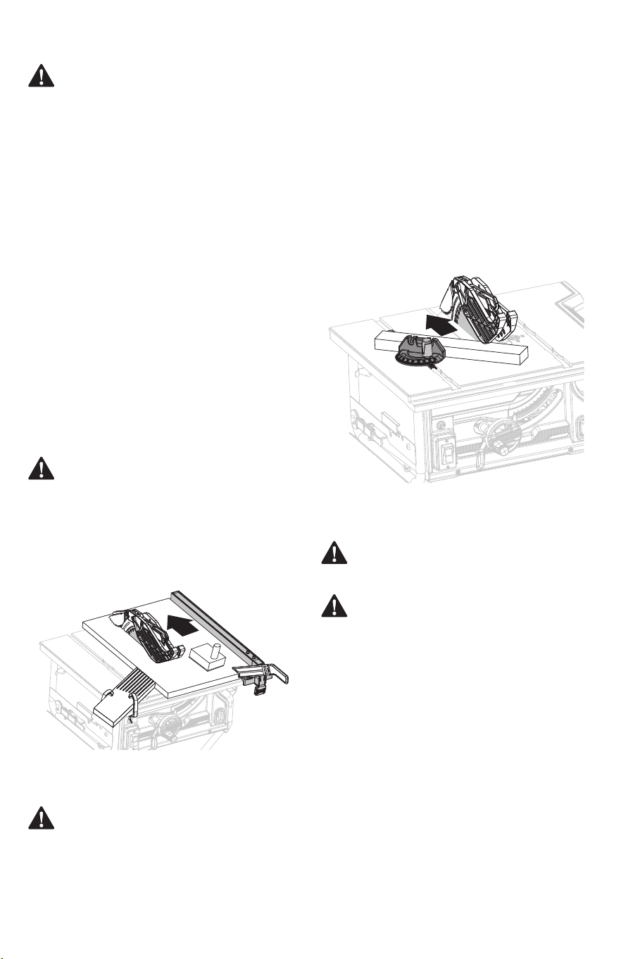
0
01
1
2
3
4
5
6
7
8
9
10
2
3
4
5
6
7
8
9
10
11
12
0
01
1
2
3
4
5
6
7
8
9
10
2
3
4
5
6
7
8
9
10
11
24
ENGLISH
Fig. 28
• Remove rip fence.
• Set blade to correct depth for workpiece.
• Set miter gauge to the desired angle and tighten lock
knob.
• Make sure the wood is clear of the blade before turning
on the saw.
• Turn the saw on.
• Let the blade build up to full speed before moving the
workpiece into the blade.
• Hold the workpiece rmly with both hands on the miter
gauge and feed the workpiece into the blade.
Making a miter cut (Fig. 29)
Making a bevel cross cut (Fig. 30)
• Remove rip fence.
• Unlock bevel locking lever.
• Adjust bevel angle to desired setting.
• Lock bevel locking lever.
• Set blade to correct depth for workpiece.
• Set miter gauge to 0° and tighten lock knob.
• Make sure wood is clear of blade before turning on saw.
• Turn saw on.
• Let blade build up to full speed before moving
workpiece into blade.
• Hold the workpiece rmly with both hands on the miter
gauge and feed the workpiece into the blade.
WARNING: Make sure the blade guard assembly is
installed and working properly to avoid possible
serious injury.
WARNING: The miter gauge must be on the right
side of the blade to avoid trapping the wood and
causing kickback. Placement of the miter gauge to
the left of the blade will result in kickback and the risk
of serious personal injury.
• Set blade to correct depth for workpiece.
• Position the rip fence the desired distance from the
blade for the cut and securely lock the handle.
• When ripping a long workpiece, place a support the
same height as the table surface behind the saw, and on
the sides as needed, for the cut work.
• Install feather board in the appropriate position for the
cut being made.
• Make sure the wood is clear of the blade before turning
on the saw.
• Turn the saw on.
• Position workpiece at on table with edge ush against
rip fence. Let blade build up to full speed before feeding
workpiece into blade.
• Once blade has made contact with workpiece, use hand
closest to rip fence for guidance. Make sure edge of
workpiece remains in solid contact with both rip fence
and surface of table. If ripping a narrow piece, attach the
sub fence assembly to rip fence, use push stick and/or
push blocks to move piece through cut and past blade.
• When cut is complete, turn saw off. Wait for blade to
come to a complete stop before removing workpiece.
WARNING: Make sure the blade guard assembly is
installed and working properly to avoid possible
serious injury.
WARNING: Make sure the blade guard assembly is
installed and working properly to avoid possible
serious injury.
WARNING: When ripping, always apply the
workpiece feeding force between the fence and the
saw blade. Use a push stick when the distance
between the fence and the saw blade is less than 6 in.
(152 mm), and use a push block when this distance is
less than 2 in. (51 mm). Cutting aids will keep your
hand at a safe distance from the saw blade.
Making a rip cut (Fig. 28)
Fig. 29
• When the cut is made, turn the saw o. Wait for the
blade to come to a complete stop before removing the
workpiece.
NOTICE: The hand closest to the blade should be placed on
the miter gauge lock knob and the hand farthest from the
blade should be placed on the workpiece.
NOTICE: The hand closest to the blade should be placed on
the miter gauge lock knob and the hand farthest from the
blade should be placed on the workpiece.
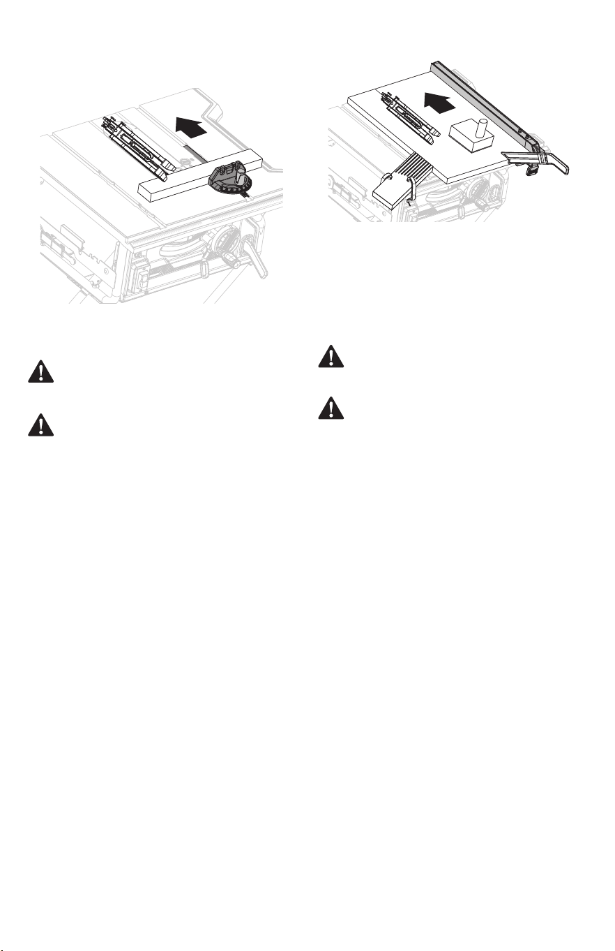
0
01
1
2
3
4
5
6
7
8
9
10
2
3
4
5
6
7
8
9
10
11
12
0
01
1
2
3
4
5
6
7
8
9
10
2 3
4
5
6
7
8
9
10
11
12
ENGLISH
25
Fig. 31
Fig. 30
Making a bevel rip cut (Fig. 31)
• Remove miter gauge.
• Install feather board in the appropriate position for the
cut being made.
• Unlock the bevel locking lever.
• Adjust bevel angle to desired setting.
• Lock bevel locking lever.
• Set blade to correct depth for workpiece.
• Position the rip fence the desired distance from the
blade for the cut and securely lock the handle.
• Make sure wood is clear of blade before turning on saw.
• When ripping a long workpiece, place a support the
same height as the table surface behind the saw, and on
the sides as needed, for the cut work.
• Turn saw on.
• Position workpiece at on table with edge push against
rip fence.
• Let blade build up to full speed before moving
workpiece into blade.
• Once blade has made contact with workpiece, use hand
closest to rip fence to guide it. Make sure the edge of
workpiece remains in solid contact with both rip fence
and surface of table. If ripping a narrow piece, attach the
sub fence assembly to the rip fence, use a push stick
and/or push blocks to move piece through cut and past
the blade.
• When cut is complete, turn saw o. Wait for blade to
come to a complete stop before removing workpiece.
• When cut is complete, turn saw o. Wait for blade to
come to a complete stop before removing workpiece.
WARNING: Make sure the blade guard assembly is
installed and working properly to avoid possible
serious injury.
WARNING: The rip fence must be on the right side of
the blade to avoid trapping the wood and causing
kickback. Placement of the rip fence to the left of the
blade will result in kickback and the risk of serious
personal injury.
Making a compound (bevel) miter cut
(Fig. 32)
• Remove the rip fence.
• Unlock the bevel locking lever.
• Adjust the bevel angle to the desired setting.
• Lock the bevel locking lever.
• Set the blade to the correct depth for the workpiece.
• Set the miter gauge to the desired angle and tighten
the lock knob.
• Make sure the wood is clear of the blade before turning
on the saw.
• Turn the saw on.
• Let the blade build up to full speed before moving the
workpiece into the blade.
• Hold the workpiece rmly with both hands on the miter
gauge and feed the workpiece into the blade.
WARNING: Make sure the blade guard assembly is
installed and working properly to avoid possible
serious injury.
WARNING: The miter gauge must be on the right
side of the blade to avoid trapping the wood and
causing kickback. Placement of the miter gauge to
the left of the blade will result in kickback and the risk
of serious personal injury.
• When the cut is made, turn the saw o. Wait for the
blade to come to a complete stop before removing the
workpiece.
NOTICE: The hand closest to the blade should be placed on
the miter gauge lock knob and the hand farthest from the
blade should be placed on the workpiece.
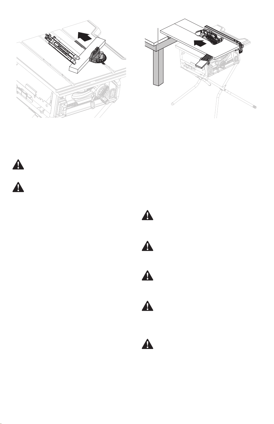
0
01
1
2
3
4
5
6
7
8
9
10
2
3
4
5
6
7
8
9
10
11
12
26
ENGLISH
Fig. 32
• Install feather board in the appropriate position for the
cut being made.
• Place a support the same height as the top of the saw
table behind the saw, and on the sides as needed, for
the cut work. Add supports to the sides as needed.
• Depending on the shape of the panel, use the rip fence
or miter gauge. If the panel is too large to use either the
rip fence or the miter gauge, it is too large for this saw.
• Make sure the wood does not touch the blade before
you turn on the saw.
• Turn the saw on.
• Position the workpiece at on the table with the edge
ush against the rip fence. Let the blade build up to full
speed before feeding the workpiece into the blade.
• Use a push stick to move the piece through the cut and
past the blade.
• When the cut is made, turn the saw o. Wait for the
blade to come to a complete stop before removing the
workpiece.
Make sure the saw is properly secured to a work surface to
avoid tipping from the weight of a large panel.
Making a large panel cut (Fig. 33)
Making a non-through cut (Fig. 34)
Non-through cuts (made with a standard 10 in. blade) can
be made with the grain (ripping) or across the grain (cross
cut). The use of a non-through cut is essential to cutting
grooves, rabbets, and dadoes. This is the only type cut that
is made without the blade guard assembly installed. Make
sure the blade guard assembly is reinstalled upon
completion of this type of cut. Read the appropriate section
which describes the type of cut in addition to this section on
non-through or dado cuts. For example, if your non-through
cut is a straight cross cut, read and understand the section
on straight cross cuts before proceeding.
WARNING: When making a non-through cut, the
blade is covered by the workpiece during most of the
cut. Be alert to the exposed blade at the start and
nish of every cut to reduce the risk of personal injury.
WARNING: To reduce the risk of serious injury when
making non-through cuts, follow all applicable
warnings and instructions listed below in addition to
those listed above for the relevant through cut.
WARNING: Never feed wood with your hands when
making any non-through cut such as rabbets or
dadoes. To avoid personal injury, always use push
blocks, push sticks, and featherboards.
WARNING: Read the appropriate section which
describes the type of cut in addition to this section on
non-through cuts. For example, if your non-through
cut is a straight cross cut, read and understand the
section on straight cross cuts before proceeding.
WARNING: Once all dado and non-through cuts are
completed, unplug saw and reinstall riving knife in
uppermost position. Install anti-kickback pawls and
blade guard.
WARNING: Make sure the blade guard assembly is
installed and working properly to avoid possible
serious injury.
WARNING: Never make freehand cuts (cuts without
the miter gauge or rip fence). Unguided workpieces
can result in serious injury.
Fig. 33
Support
• Turn saw o and unplug saw.
• Remove the blade guard and anti-kickback pawls.
• Place riving knife in “middle” position.
• Unlock the bevel locking lever.
• Adjust the bevel angle to 0°.
• Lock the bevel locking lever.
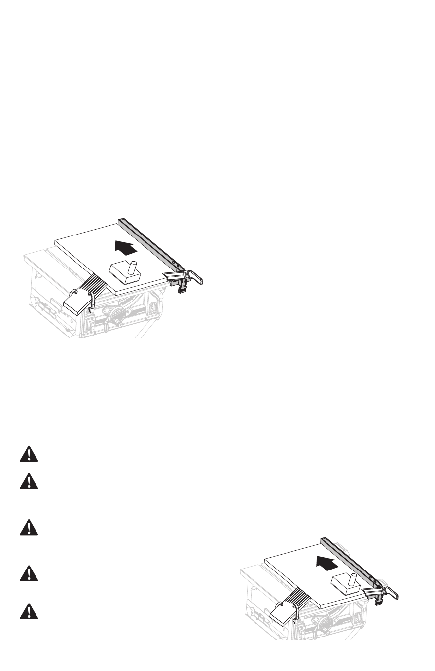
0
01
1
2
3
4
5
6
7
8
9
10
2
3
4
5
6
7
8
9
10
11
12
0
01
1
2
3
4
5
6
7
8
9
10
2
3
4
5
6
7
8
9
10
11
12
ENGLISH
27
WARNING: Once all dado and non-through cuts are
completed, unplug saw and reinstall riving knife in
uppermost position. Install anti-kickback pawls and
blade guard.
Fig. 35
Fig. 34
Making a dado cut (Fig. 35)
• Set the blade to the correct depth for the workpiece.
• Depending on the shape and size of the wood, use
either the rip fence or miter gauge.
• Plug the saw into the power source and turn the saw on.
• Let the blade build up to full speed before moving the
workpiece into the blade.
• Always use push blocks, push sticks, and/or
featherboards appropriately when making non-through
cuts to reduce the risk of serious injury.
• When the cut is made, turn the saw o. Wait for the
blade to come to a complete stop before removing the
workpiece.
• Turn saw o and unplug saw.
• Reinstall the riving knife in the “uppermost” position
then install the blade guard and anti-kickback pawls.
An optional dado table insert is required for this procedure.
(Dado table insert is sold separately, check
www.craftsman.com). All blades and dado sets must not be
rated less than the speed of this tool. This saw is designed
for use with a 8 in. (200 mm) stack dado (up to width of
1/2 in. (12.7 mm).
WARNING: When making a non-through cut, the
blade is covered by the workpiece during most of the
cut. Be alert to the exposed blade at the start and
nish of every cut to reduce the risk of personal injury.
CAUTION: Do not use an adjustable dado or molding
cutters on this saw.
WARNING: Always put all inner and outer anges in
proper location when reinstalling standard blade.
Failure to do so can result in possible injury and
damage to the tool.
WARNING: Always use push blocks, push sticks,
and/or featherboards when making dado cuts to
avoid the risk of serious injury.
• Position the workpiece at on the table with the edge
ush against the rip fence or miter gauge and hold
rmly against the saw table.
• Use a push block or push stick to move the wood
through the cut past the blade. Never push a small
piece of wood into the blade with your hand, always
use a push stick. The use of push blocks, push sticks, and
featherboards are necessary when making non-through
cuts.
• When the cut is made, turn the saw o. Wait for the
blade to come to a complete stop before removing the
workpiece.
• Turn saw o and unplug saw.
• Remove the blade guard, anti-kickback pawls, and
table insert.
• Place riving knife in “down” position.
• Remove the blade nut, outer ange, and saw blade.
• Mount the dado blade, according to manufacturer
instructions, using the blade and chippers appropriate
for the desired width of cut.
• Reinstall the blade nut.
• Make sure the blade nut is fully engaged and the arbor
extends past a securely tightened blade nut.
• Install the dado table insert and rotate the blade by
hand to make sure it turns freely then lower the blade.
• Depending on the shape and size of the wood, use
either the rip fence or miter gauge.
• Install feather board in the appropriate position for the
cut being made.
• Turn the saw on.
NOTICE: Always store the outer ange and table insert in a
secure location.
NOTICE: The outer ange may be used provided the arbor
shaft extends slightly beyond the arbor nut.
NOTICE: Make sure the wood does not touch the blade before
you turn on the saw. Let the blade build up to full speed before
feeding the workpiece into the blade.
Once all non-through cuts are completed:
• Turn saw o and unplug saw.
• Remove the dado table insert and reinstall standard
table insert.
• Remove the dado blade and reinstall the standard saw
blade.
• Reinstall the riving knife in the “uppermost” position
then install the blade guard and anti-kickback pawls.
Once all dado cuts are completed:
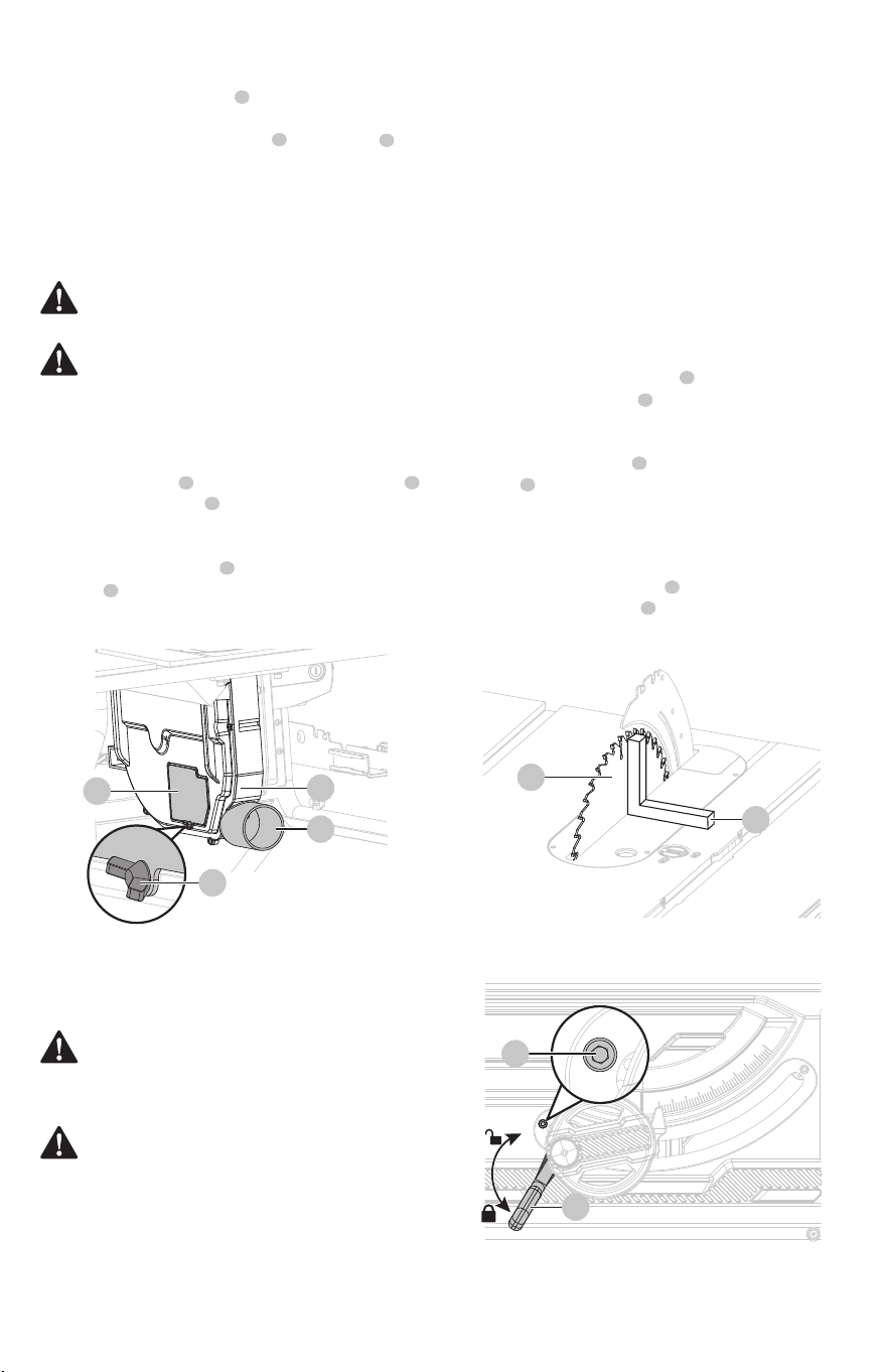
28
ENGLISH
This saw features a dust chute for convenience in
discharging sawdust. A standard utility vacuum can be
attached to the dust extraction port on dust chute ,
located under the back side of the saw cabinet.
During periods of extended use, the dust chute should be
emptied and cleaned to prevent buildup of sawdust and to
make sure there are no obstructions that could hinder
maximum performance.
• Turn saw o and unplug saw.
• Loosen the screw at the left side of the dust chute .
• Open the small bae .
• Shake out any sawdust and wipe with a clean dry cloth,
as needed.
• Replace the small bae and securely tighten the
screw .
To clean the dust chute:
• Unlock the bevel locking lever .
• Loosen the 0° set screw (located at the left of the
bevel track on the front) with 4 mm hex key (not
supplied).
• Place a framing square (not supplied) beside the
blade on the right. The edge of the square and the
saw blade should be parallel.
• Lock the bevel locking lever .
• Tighten the 0° set screw . Check again for squareness
and continue to adjust if needed.
If the blade is not perfectly vertical (0°) (Fig. 37a-37b):
1
2
1
3
1
2
1
1
2
3
4
4
4
3
2
1
3
1
3
4
4
2
Dust collection (Fig. 36)
ADJUSTMENTS
WARNING: Before performing any adjustment, make
sure tool is unplugged from power supply and switch
is in o position. Failure to do so could result in serious
personal injury.
WARNING: Make sure the blade guard is reinstalled
immediately after making any adjustment which
requires it to be removed. Failure to heed this
instruction could result in serious personal injury.
Fig. 36
Fig. 37a
Fig. 37b
This saw has positive stops that will quickly position the saw
blade at 90° (0°) or 45° to the table. Angle settings of saw
have been set at the factory and, unless damaged in
shipping, should not require setting during assembly. After
extensive use, they may need to be checked.
To set the blade at 0° and 45°
(Fig. 37a-37d)
• Turn saw o and unplug saw.
• Raise the blade to the maximum height by turning the
height adjusting handle clockwise.
• Remove the anti-kickback pawls and blade guard.
NOTICE: Make sure that the square contacts the at part of
the saw blade, not the blade teeth.
CAUTION: It is strongly recommended to connect a
dust collection system to the dust extraction port.
WARNING: Table saw must be regularly checked for
dust built up and cleaned frequently, otherwise there
is a risk of heat built up and potential re.
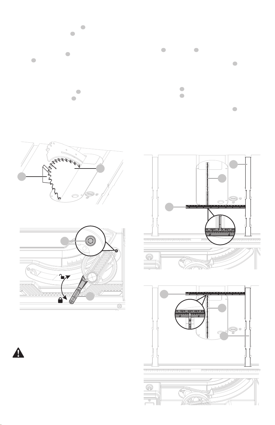
001 12345678910 2 3 4 5 6 7 8 9 10
001 12345678910 2 3 4 5 6 7 8 9 10
ENGLISH
29
• Unlock the bevel locking lever .
• Loosen the 45° set screw (located at the right of the
bevel track on the front) with 4 mm hex key (not
supplied).
• Place a triangle square (not provided) beside the
blade on the left. The edge of the square and the saw
blade should be parallel.
• Turn saw o and unplug saw.
• Remove the blade guard and anti-kickback pawls.
• Place the riving knife in “down” position.
• Raise the blade by turning the height adjusting handle.
• Mark beside one of the blade teeth at the front of the
blade . Using a ruler (not included), measure the
distance from the inside face of the blade tooth to the
left edge of the right miter gauge groove .
• Turn the blade so the marked tooth is at the back.
• Move the ruler to the rear and again measure the
distance from the inside face of the blade tooth to the
left edge of the right miter gauge groove . If the
distances are the same, the blade and the miter gauge
groove are parallel.
• Place the riving knife in “uppermost” position.
• Replace blade guard and anti-kickback pawls.
4
1
1
1
6
5
3
2
2
3
WARNING: The blade must be made parallel to the
miter gauge groove so the wood does not bind
resulting in kickback. Failure to do so could result in
serious personal injury.
• Lock the bevel locking lever .
• Tighten the 45° set screw . Check again for squareness
and continue to adjust if needed.
• If needed, adjust the bevel indicator to 45°.
• Make a test cut.
If the blade is not an exact 45° (Fig. 37c-37d):
6
5
4
1 2
3
3
1
2
1
1
5
NOTICE: Make sure that the square contacts the at part of
the saw blade, not the blade teeth.
NOTICE: For greater accuracy, place the marked blade tooth
on top of the ruler.
Fig. 37c
Fig. 37d
Fig. 38a
Fig. 38b
Adjusting the blade parallel to the miter
gauge groove (Fig. 38a-38c)
Do not loosen any bolts for this adjustment until you have
checked with a ruler and made test cuts to be sure
adjustments are necessary. Once the bolts are loosened,
these items must be reset.
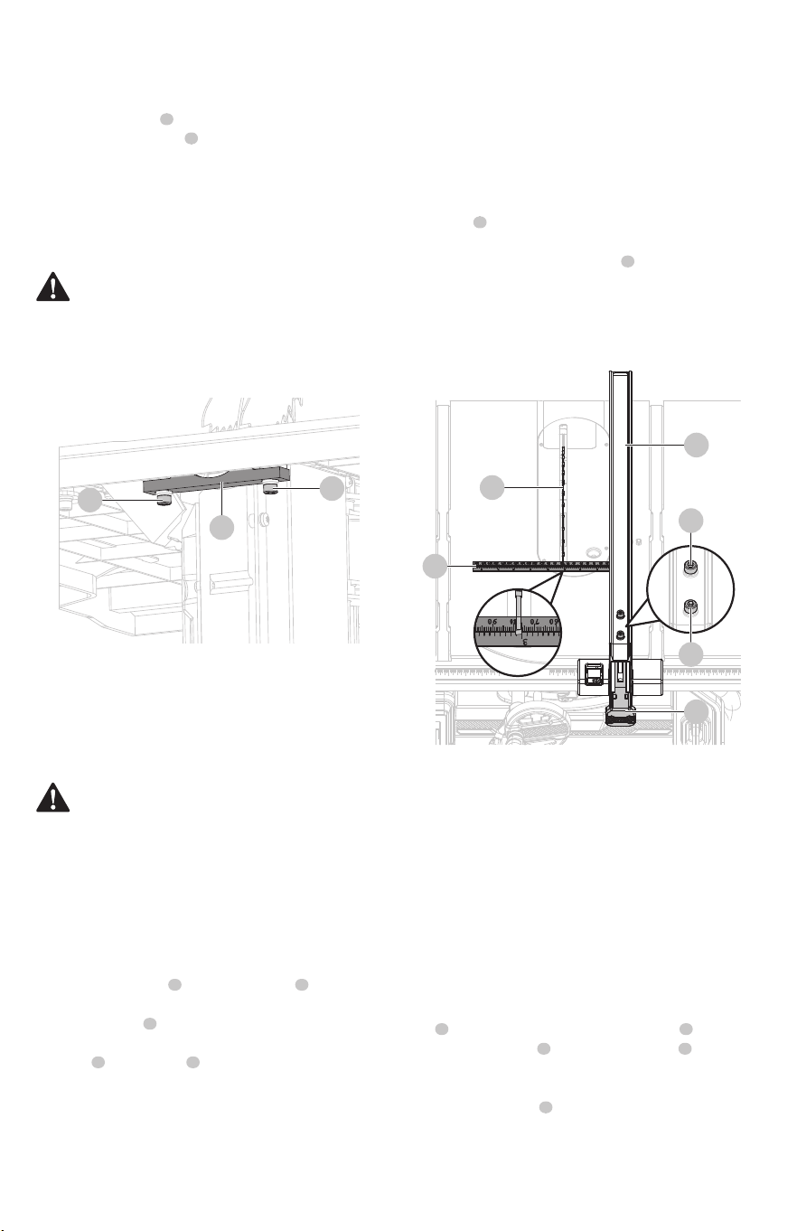
001 12345678910 2 3 4 5 6
7 8 9 10 11
12
001 12345
678910 2 3 4 5 6 7 8 9 10 11 12
30
ENGLISH
Begin with the blade at a zero angle (straight up).
• Turn saw o and unplug saw.
• Loosen the rip fence by lifting the locking handle.
• Using a framing square (not included), set the rip fence
2 in. from the tip edge of the saw blade .
• Loosen the screw on the scale indicator and align
red line on the scale indicator with the 2 in. mark as
shown.
• Tighten the screw and check the dimension and the
rip fence.
• Unlock the rip fence.
• Use the 5 mm hex key (not supplied) to loosen the two
screws located on top of the rip fence.
• Adjust the rip fence.
• Alternately retighten the screws . Recheck alignment.
• Repeat steps as needed until rip fence is correctly
aligned.
• Replace blade guard and anti-kickback pawls.
• Place the riving knife on “uppermost” position.
• Turn saw o and unplug saw.
• Remove the blade guard and anti-kickback pawls.
• Place the riving knife in “down” position.
• Raise the blade by turning the height adjusting handle.
• Verify the blade is parallel to the miter gauge groove as
described in the “Adjusting the blade parallel to the
miter gauge groove” section.
• Move the rip fence near the saw blade (about three
inches away) and lock the rip fence in place with the
locking handle .
• Mark beside one of the blade teeth at the front of the
blade . Using a ruler (not included), measure the
distance from the inside face of the blade tooth to the
to the inside face of the rip fence.
• Turn the blade so the marked tooth is at the back.
• Move the ruler to the rear and again measure the
distance from the inside face of the blade tooth to the
inside face of the rip fence. If the distances are the same,
the blade and the rip fence are parallel.
If the distances are dierent:
NOTICE: For greater accuracy, place the marked blade tooth
on top of the ruler.
NOTICE: The blade guard and anti-kickback pawls must be
removed to perform this adjustment. Reinstall the blade guard
and anti-kickback pawls when the adjustment is complete.
• Remove the blade guard and riving knife. Raise the
blade by turning the height adjusting handle.
• Loosen two bolts with 5 mm hex key (not supplied),
adjust the xing plate left or right until the blade is
square.
WARNING: A misaligned rip fence can cause
kickbacks and jams. To reduce the risk of injury,
always maintain proper rip fence alignment.
WARNING: To reduce the risk of injury from kickback,
align the rip fence to the blade following any blade
adjustments. Always make sure the rip fence is
parallel to the blade before beginning any operation.
4
5
1 2
3
3 4
21
3
2 4
5
5
1
5
5
5
3
2
4
4
4
The rip fence must be parallel to the saw blade and the
miter gauge grooves.
To check the alignment of the rip fence to
the blade (Fig. 39)
Use the red line on the indicator on the rip fence to position
the fence along the scale on the front rail.
To adjust the rip fence scale indicator
(Fig. 40)
Fig. 38c
Fig. 39
NOTICE: The bolts and xing plate are located under the
working table in the back of the saw.
• Check again for squareness and continue to adjust if
needed.
If the distances are dierent:
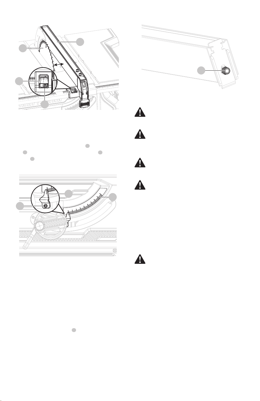
0
01
1
2
3
4
5
6
7
8
9
10
2
3
4
5
6
7
8
9
10
11
12
0
01
1
2
3
4
5
6
7
8
9
10
2
3
4
5
6
7
8
9
10
11
12
0
01
1
2
3
4
5
6
7
8
9
10
2
3
4
5
6
7
8
9
10
11
12
1 2 3
1 2 3
1 2 3
1 2 3
0°
5°
10°
15°
20°
25°
30°
35°
40°
45°
0°
ENGLISH
31
• Lock the rip fence in place.
• Try moving the fence from side-to-side. If the fence
moves, tighten the lock nut 1/4 turn.
• With the rip fence in the locked position, recheck rip
fence parallelism with the blade and adjust if necessary.
Avoid using solvents when cleaning plastic parts. Most
plastics are susceptible to damage from various types of
commercial solvents and may be damaged by their use. Use
clean cloths to remove dirt, dust, oil, grease, etc.
• Periodically check all clamps, nuts, bolts, and screws for
tightness and condition. Make sure the table insert is in
good condition and in position.
• Check the blade guard assembly.
• To maintain the table surfaces, fence, and rails,
periodically apply paste wax to them and bu to
provide smooth functioning.
• Protect the blade by cleaning out sawdust from
underneath the table and in the blade teeth. Use a resin
solvent on the blade teeth.
• Clean plastic parts only with a soft damp cloth. DO NOT
use any aerosol or petroleum solvents.
If the red line on the bevel indicator is not at zero when the
saw blade is at 90°, adjust the indicator by loosening the
screw and setting it at 0° on the bevel scale . Retighten
the screw .
WARNING: When servicing, use only identical
replacement parts. Use of any other part may create a
hazard or cause product damage.
WARNING: Always wear eye protection with side
shields marked to comply with ANSI Z87.1 during
product operation. If operation is dusty, also wear a
dust mask.
WARNING: Before performing any maintenance,
make sure the tool is unplugged from the power
supply and switch is in the o position.
WARNING: Make sure the blade guard and
anti-kickback pawls are reinstalled immediately after
nishing any maintenance which requires them to be
removed. Failure to heed this instruction could result
in serious personal injury.
WARNING: Do not at any time let brake uid,
gasoline, petroleum-based products, penetrating oils,
etc., come in contact with plastic parts. Chemicals can
damage, weaken, or destroy plastic which may result
in serious personal injury.
1
2
2
1
3
3
1
2
4
2 in.
3
1
2
1
Fig. 41
Fig. 40
Fig. 42
To adjust bevel indicator (Fig. 41)
MAINTENANCE
General maintenance
The locking handle on the rip fence should hold the rip
fence securely against the front and back rails. The handle
should not be dicult to push down and lock. To assure
proper fence lock adjustment:
To check the tightness of the rip fence
locking handle (Fig. 42)
2 in.
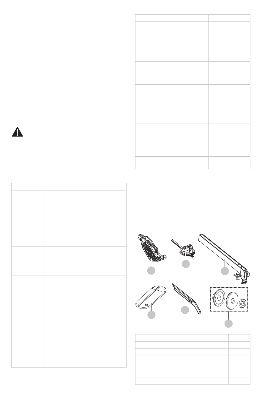
32
ENGLISH
WARNING: To avoid injury from an accidental start,
turn the switch OFF and always remove the plug from
the power source before making any adjustments.
All electrical or mechanical repairs should be done
only by qualied service technicians. Contact
CRAFTSMAN Authorized Service Center.
Consult CRAFTSMAN Authorized Service Center if for
any reason the motor will not run.
TROUBLESHOOTING
REPLACEMENT PARTS LIST
All of the bearings in this tool are lubricated with a
sucient amount of high grade lubricant for the life of the
unit under normal operating conditions. Therefore, no
further lubrication is required.
FREE WARNING LABEL REPLACEMENT: If your warning labels
become illegible or are missing, call 1-888-331-4569 for a
free replacement.
For replacement parts, call our customer service department
at 1-888-331-4569, 8 a.m. - 8 p.m., EST, Monday - Friday.
Lubrication
After operation of the tool has been completed, check that
the following has been performed:
• Switch is in OFF position.
• Power plug has been removed from the receptacle.
When the tool is not use, keep it stored in a dry place out of
the reach of children.
Storage
A
B
C
D
E
F
PART
Blade guard
Miter gauge
Rip fence
Table insert
Push stick
Blade locking assembly
127092201
127092202
127092203
127092204
127092205
127092206
DESCRIPTION PART #
PROBLEM CAUSE SOLUTION
Saw does not make
accurate 90˚ or 45˚
cuts.
• Positive stops located on
bevel track on the front
need adjusting(Bevel
Cuts).
• Miter gauge is
misaligned (Miter
Cuts).
• Adjust the positive stops.
• Adjust the miter gauge.
Height/bevel
adjusting
handwheel is hard
to turn.
• Gears or screw post
inside cabinet are
clogged with saw dust.
• Clean the gears or screw
post.
Saw does not start. • Motor cord or wall cord
is not plugged in.
• Circuit fuse is blown.
• Circuit breaker is tripped.
• Cord or switch is
damaged.
• Plug in motor cord or
wall cord.
• Replace circuit fuse.
• Reset circuit breaker.
• Have the cord or switch
replaced at your nearest
authorized service center.
Blade makes poor
cuts.
• Blade is dull or dirty.
• Blade is wrong type for
cut being made.
• Blade is mounted
backwards.
• Clean, sharpen, or
replace blade.
• Replace with correct
type.
• Remount blade.
Motor labors in
rip cut.
• Blade not proper for rip
cut.
• Change blade; rip blade
typically has fewer teeth.
Rip fence does not
lock at rear.
PROBLEM
• Clamp screw is out of
adjustment.
• Adjust clamp screw
clockwise.
Rip fence does not
move smoothly.
• Rip fence not mounted
correctly.
• Rails are dirty or sticky.
• Clamp screw is out of
adjustment.
• Remount the rip fence.
• Clean and wax rails.
• Adjust clamp screw
counterclockwise.
Excess vibration. • Blade is out of balance.
• Blade is damaged.
• Saw is not mounted
securely.
• Work surface is uneven.
• Blade is warped.
• Replace blade.
• Replace blade.
• Tighten all hardware.
• Reposition on at
surface. Adjust legs of
optional stand.
• Check saw blade
installation. Replace
blade if necessary.
Wood edges away
from rip fence when
ripping.
• Blade not properly
sharpened or set.
• Resharpen or set blade.
Cutting binds or
burns work.
• Blade is dull.
• Blade is heeling.
• Work is fed too fast.
• Rip fence is misaligned.
• Wood is warped.
• Riving knife is out of
alignment.
• Replace or sharpen blade.
• See “Adjusting the blade
parallel to the miter
gauge groove”.
• Slow the feed rate.
• Align the rip fence.
• Replace the wood.
Always cut with convex
side to table surface.
• Align the riving knife
and saw blade.
CAUSE SOLUTION
A
E
D
F
B
C

ENGLISH
33
Thank you for your purchase. Register your product nowfor:
•
WARRANTY SERVICE: Registering your product will help
you obtain more ecient warranty service in case there
is a problem with yourproduct.
• CONFIRMATION OF OWNERSHIP: In case of an insurance
loss, such as re, ood or theft, your registration of
ownership will serve as your proof ofpurchase.
• FOR YOUR SAFETY: Registering your product will allow us
to contact you in the unlikely event a safety notication
is required under the Federal Consumer SafetyAct.
Register online at www.craftsman.com/registration
Register Online
• This table saw is warranted to the original purchaser
from the original purchase date for three (3) years
subject to the warranty coverage described herein.
• This table saw is warranted to be free from defects in
material and workmanship. If you believe that the table
saw is defective at any time during the specied
warranty period, simply return the table saw to the place
of purchase for a free replacement or refund or call
1-888-331-4569 for warranty services.
• This warranty is void if: defects in materials or
workmanship or damages result from repairs or
alterations which have been made or attempted by
others or the unauthorized use of nonconforming parts;
the damage is due to normal wear, damage is due to
abuse (including overloading of the tool beyond
capacity), improper maintenance, neglect or accident; or
the damage is due to the use of the tool after partial
failure or use of improper accessories or unauthorized
repair or alteration. This warranty gives you specic legal
rights, and you may also have other rights that vary from
state to state.
• For questions, warranty claims, and/or warranty
replacement parts, call our customer service department
at 1-888-331-4569.
THREE-YEAR LIMITED WARRANTY