Loading ...
Loading ...
Loading ...
24 3. 71/Connections
Inputs on the front of the TV offer the most conve-
nient way to connect a camcorder. If your TV model
does not have a front input matching the camcorder's
output, use one of the matching jacks on the back of
the TV.
Jacks on the TV front
panel offer the most
convenient way to
connect a camcorder
Component Y Pb Pr Video Connection
Required: Analog stereo audio and component video
cables supplied with the camcorder.
Note: Your model may have component video inputs
on the front of the TV as shown in the diagram
below. Otherwise, use a set of component
video and audio jacks on the back of the TV.
1. Connect component video cables from VIDEO OUT
on the camcorder to one of the TV's sets of COM-
PONENT jacks.
2. Connect left (white) and right (red) audio cables
from AUDIO OUT on the camcorder to AUDIO L and
AUDIO R on the TV.
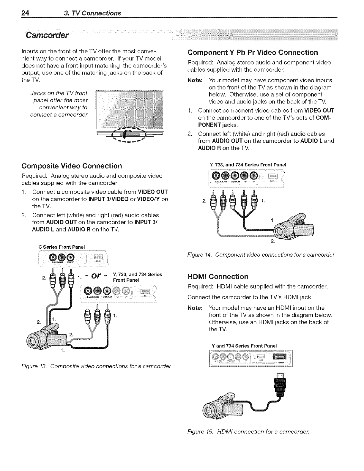
Composite Video Connection
Required: Analog stereo audio and composite video
cables supplied with the camcorder.
1. Connect a composite video cable from VIDEO OUT
on the camcorder to INPUT 3/VIDEO or VIDEO/Y on
the TV.
2. Connect left (white) and right (red) audio cables
from AUDIO OUT on the camcorder to iNPUT 3/
AUDIO L and AUDIO R on the TV.
C Series Front Panel
Y, 733, and 734 Series
Front Panel
1.
Y, 733, and 734 Series Front Panel
2.
Figure 14. Component video connections for a camcorder
HDMI Connection
Required: HDMI cable supplied with the camcorder.
Connect the camcorder to the TV's HDMI jack.
Note: Your model may have an HDMI input on the
front of the TV as shown in the diagram below.
Otherwise, use an HDMI jacks on the back of
the TV.
Y and 734 Series Front Panel
Figure 13. Composite video connections for a camcorder
Figure 15. HDMI connection for a camcorder.
Loading ...
Loading ...
Loading ...