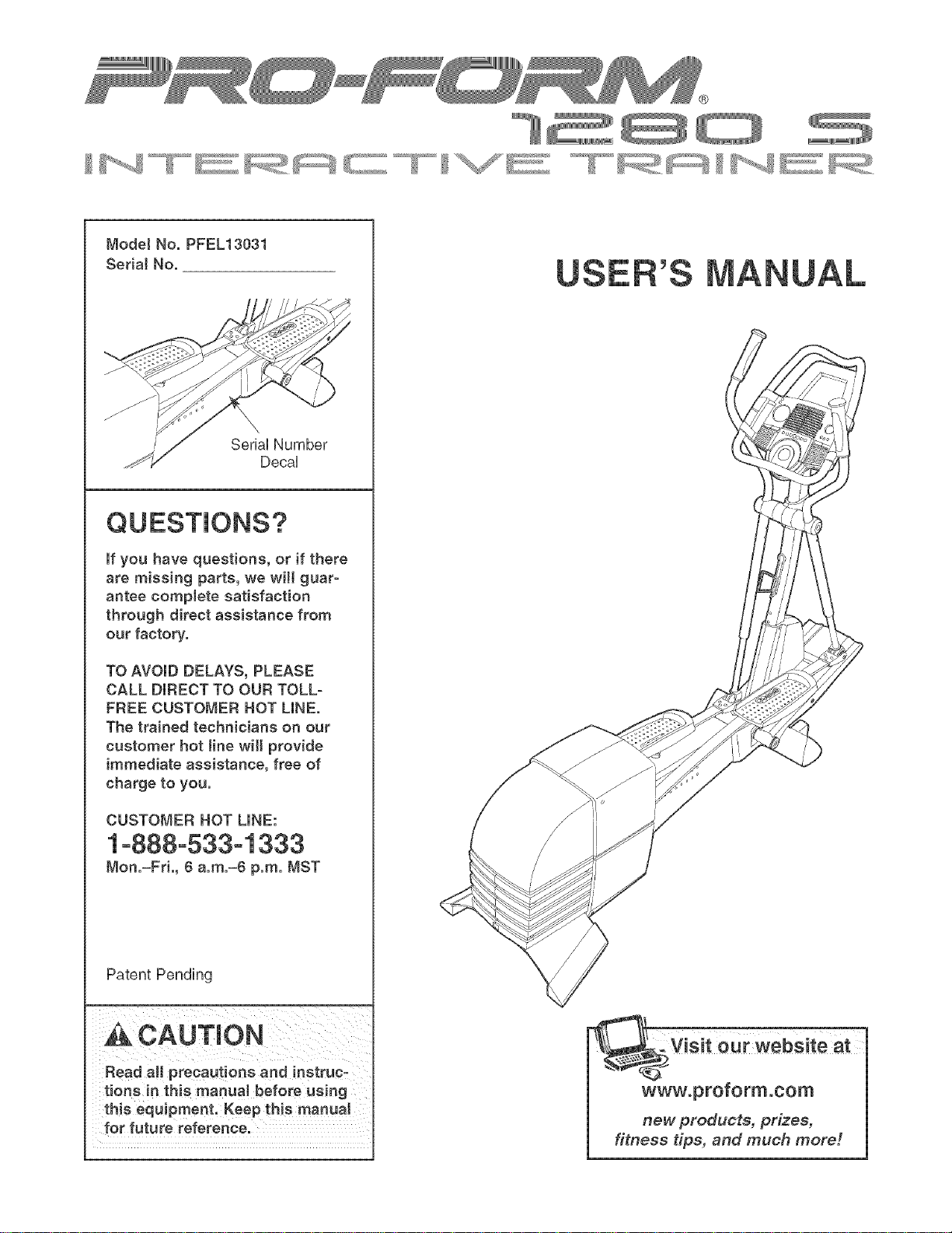
Mode!No,PFEL13031
Seria!No,
SeriaUNumber
DecaU
QUESTmONS?
If you have questions, or if there
are missing parts, we will guar-
antee complete satisfaction
through direct assistance from
our factory.
TO AVOID DELAYS, PLEASE
CALL DIRECT TO OUR TOLL-
FREE CUSTOMER HOT LINE,
The trained technicians on our
customer hot tine will provide
immediate assistance, free of
charge to you.
CUSTOMER HOT LINE:
1o888o533o1333
Mon.=Fri., 6 a.m.=6 p.m. MST
Patent Pending
CAUTION
Read all precautions and instruc-
tions in this manuat before using
this equipment. Keep this manual
for future reference.
, Visit our website at
®
TABLE OF CONTENTS
iMPORTANT PRECAUTIONS ................................................................ 3
BEFORE YOU BEGIN ...................................................................... 4
ASSEMBLY ............................................................................... 5
HOW TO USE THE ELLHPTHCALEXERCHSER .................................................. 11
MAHNTENANCE AND TROUBLESHOOTHNG ................................................... 22
CONDHTHONHNGGUHDELHNES............................................................... 23
PART LiST .............................................................................. 24
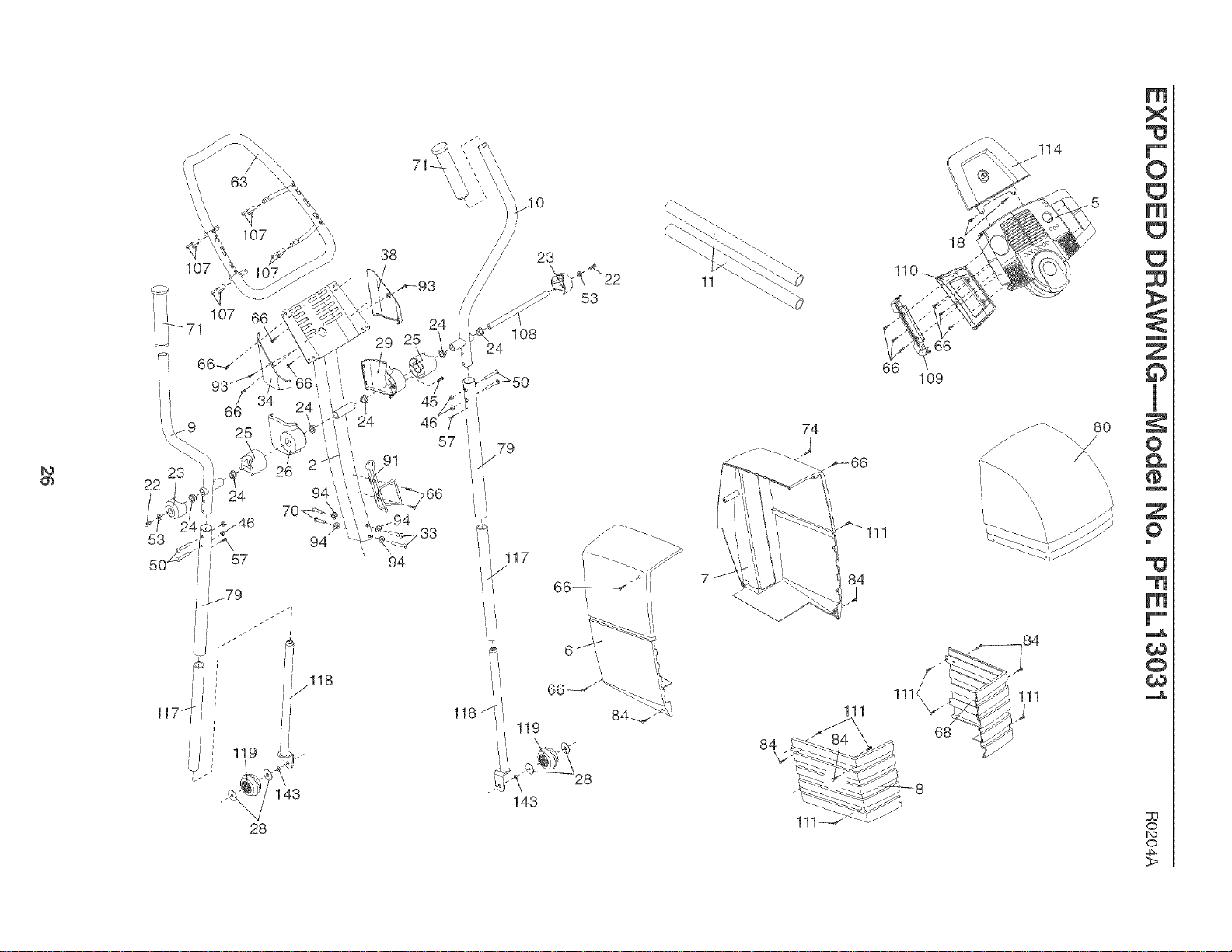
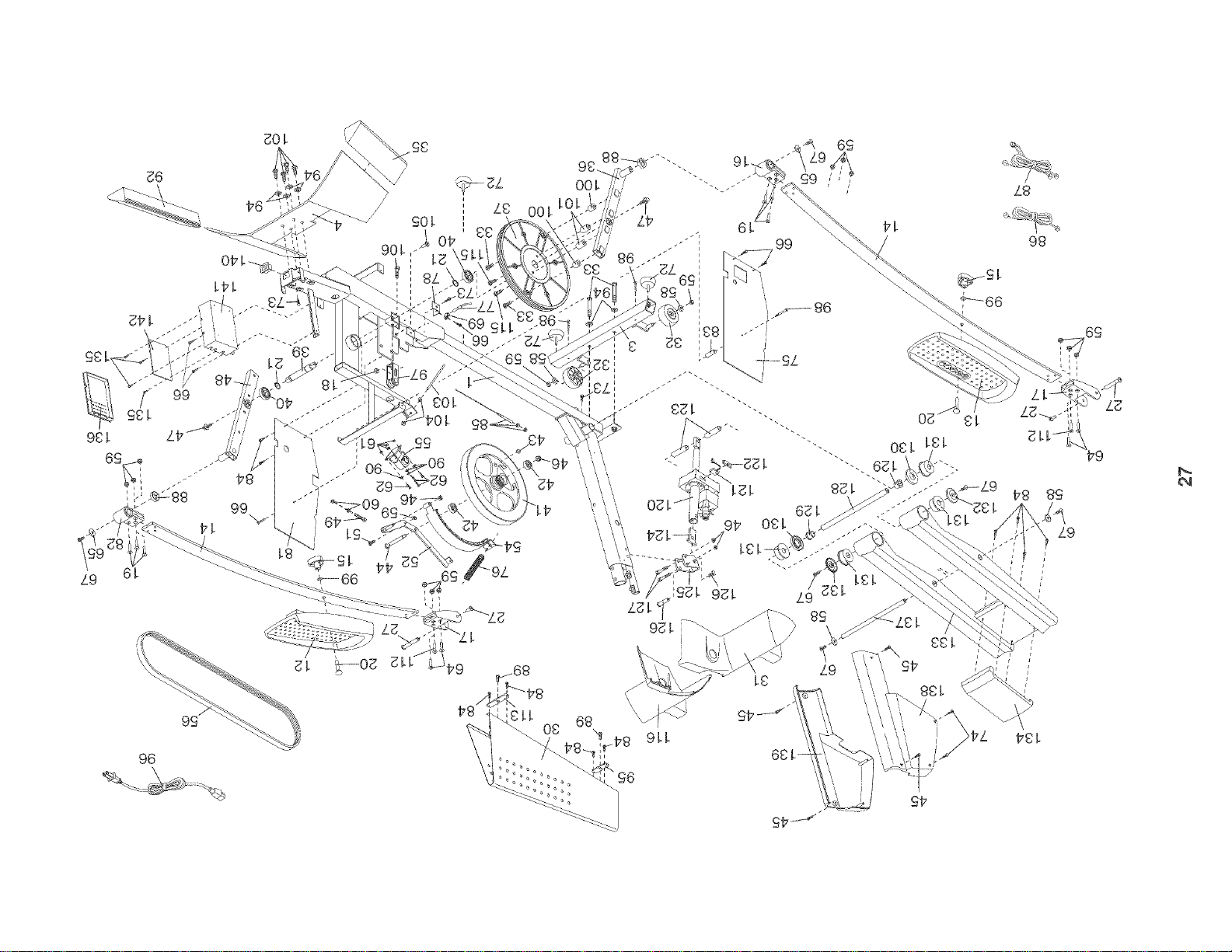
EXPLODED DRAWHNG .................................................................... 26
HOW TO ORDER REPLACEMENT PARTS ............................................. Back Cover
LHMHTEDWARRANTY .............................................................. Back Cover
PROFORM is a registered trademark of HCONHeaHth& Fitness, Hnc,
2
iMPORTANT PRECAUTIONS
WARNING: Toreducetheriskofse.ousinjury, readthefollowingimportantprecau-
tionsbefore using the elliptical exerciser.
1. Read all instructions in this manual before
using the elliptical exerciser.
11. Keep your back straight when using the ellip-
tical exerciser; do not arch your back.
2. it is the responsibility of the owner to ensure 12. If you feel pain or dizziness while exercis-
that all users of the eilipticaJ exerciser are
adequately informed of aJl precautions.
3. The elliptical exerciser is intended for
home use only. Do not use the elliptical
exerciser in a commercial, rental or institu-
tional setting.
ing, stop immediately and cool down.
13. When you stop exercising, allow the pedals
to slowly come to a complete stop. The ellip-
tical exerciser does not have a free wheel;
the pedals will continue to move until the
flywheel stops.
.
PJace the elliptical exerciser on a level sur-
face, with a mat beneath it to protect the
floor or carpet. Keep the eiJiptical exerciser
indoors,away from moistureand dust.
5. inspect and properly tighten allparts reguo
larly. RepJace any worn parts immediately.
8. Keep children under !2 and pets away from
the elii ptical exerciser at all times.
7. The elliptieaJ exerciser should not be used
by persons weighing more than 250 pounds.
8.
Wear appropriate exercise clothes when
using the eIHpticaJ exerciser. Always wear
athletic shoes for foot protection while e×er-
cising.
9. HoJd the center handlebar or the left and right
handlebars while mounting dismounting, or
using the elliptical exerciser.
10. The pulse sensor is not a medical device.
Various factors may affect the aCCUracy of
heart rate readings. The putse sensor is
intended only as an exercise aid in determin-
ing heart rate trends in general.
14. Always unplug the power cord immediately
after use and before cleaning the elliptical
exerciser.
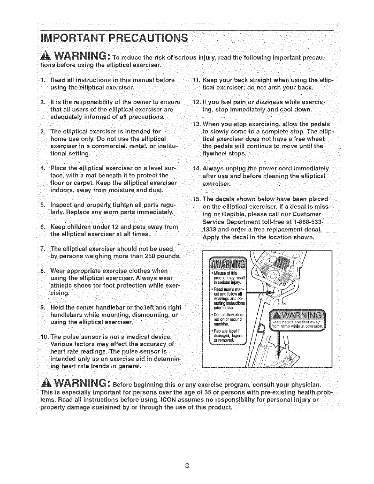
15. The decals shown below have been placed
on the elliptical exerciser, if a decal is miss-
i[tg or iHegibJe, please call our Customer
Service Department toiFfree at 1-888-533-
1333 and order a free replacement decal.
Apply the decaJ in the location shown.
, Misuseofthis
productmayresult
insedousiniury.
, Readuser'sman-
ualandfollowall
warningsandop-
eretingJnstructiona
0ri0r to ese.
,DonotaJlowchild°
ran O[I or 8roL_na
maanlRe.
WARNING: Beforebegino ngthisoranyexerciseprogram,oonsuJtyourphysician.
This is especially important for persons over the age of 35 or persons with pre-existing heaJth prob-
lems. Read aH instructions before using. ICON assumes no responsibility for personal injury or
property damage sustained by or through the use of this product.
3
BEFORE YOU BEGIN
Thank you for selecting the new PROFORM _ 1280 S
eiHptbai exerciser, The PROFORM _ 1280 S is an
incredibiy smooth exerciser that moves your feet in a
naturai eiHptbai path, minimizing the impact on your
knees and ankies, And the unique 1280 S features
adjustabie resistance and a state-of°the°art console to
heip you get the most from your exercise, Weicome to
a whole new worid of natural eiHptbai-motion exercise
from PROFORM,
For your benefit, read this manual carefully before
you use the eltiptica! exerciser, if you have ques-
tions after reading this manual, call our Customer
Service Department toll-free at 1o888o533o1333,
Monday through Friday, 6 a,m, until 6 p,m, Mountain
Time (excluding holidays), To help us assist you,
please note the product model number and serial
number before calling, The model number is
PFEL13031, The serial number can be found on a
decal attached to the elliptical exerciser (see the front
cover of this manual for the location of the decal),
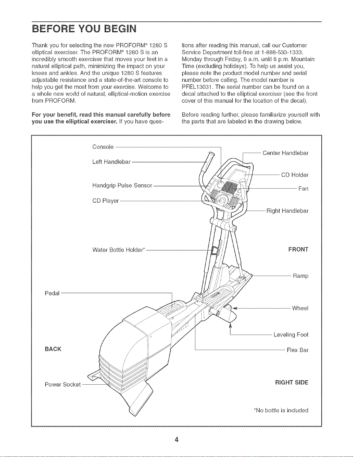
Before reading further, please familiarize yourself with
the parts that are labeled in the drawing below,
Console
Left Handlebar
Handgrip Pulse Sensor
CD Hayer
Handlebar
CD Holder
Fan
ight Handlebar
Water Bottle Holder*
FRONT
Ramp
Pedal
BACK
Leveling Foot
Flex Bar
Power Socket
RIGHT SIDE
*No bottle is included
4
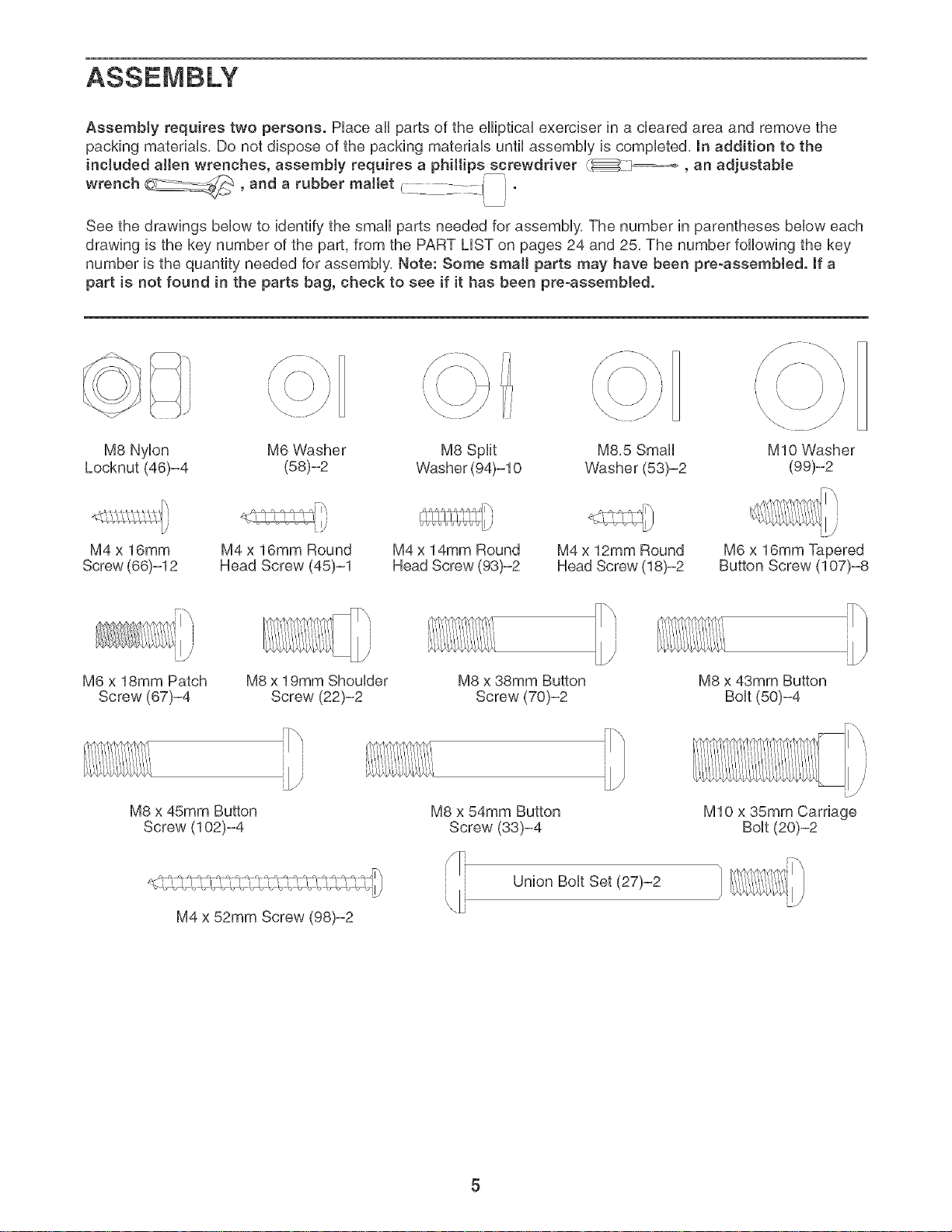
AssemMy requires two persons. Piace ali parts of the eiHpticai exerciser in a cieared area and remove the
packing materiais, Do not dispose of the packing materiais until assembiy is compieted, In addition to the
included allen wrenches, assembly requires a phillips screwdriver {_ _, an adjustable
wrench __ and a rubber mattet .... ' '
See the drawings bellow to identify the smali parts needed for assembiy, The number in parentheses bellow each
drawing is the key number of the part, from the PART LiST on pages 24 and 25, The number following the key
number is the quantity needed for assembiy, Note: Some small parts may have been pre-assembled. If a
part is not found in the parts bag, check to see if it has been pre-assembted.
\\
\
I
'\
\
M8 Nyion M6 Washer M8 Spiit M8,5 Smali MIO Washer
Locknut (46)-4 (58)-2 Washer (94)-10 Washer (53)-2 (99)-2
M4 x 16mm
Screw (66)-12
M4 x 16mm Round
Head Screw (45)-1
M4 x 14mm Round
Head Screw (93)-2
M4 x 12mm Round
Head Screw (18)-2
M6 x 16mm Tapered
Button Screw (107)-8
M6 x 18mm Patch
Screw (67)-4
M8 x 19mm Shoulder
Screw (22)-2
M8 x 38mm Button
Screw (70)-2
M8 x 43mm Button
Bolt (50)-4
M8 x 45mm Button
Screw (102)-4
M4 x 52mm Screw (98)-2
M8 x 54mm Button
Screw (33)-4
Union Bolt Set (27)-2
MIO x 35mm Carriage
U./
1. 1
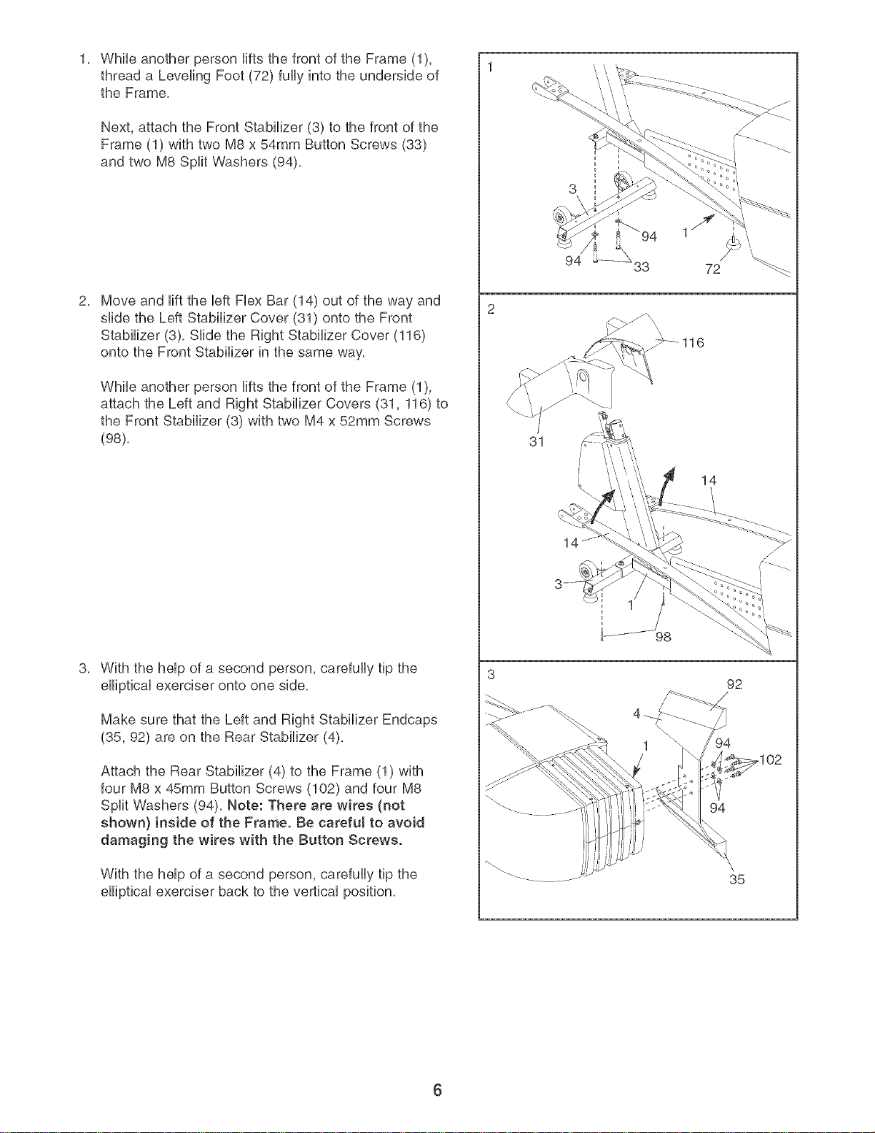
WhileanotherpersonHftsthefrontoftheFrame(1),
threada LevelingFoot(72)fullyintotheundersideof
theFrame,
Next,attachtheFrontStabilizer(3)tothefrontofthe
Frame(1)withtwoM8x54mmButtonScrews(33)
andtwoM8SplitWashers(94).
MoveandHfttheUeftFUexBar(14)outofthewayand
slidetheLeftStabilizerCover(31)ontotheFront
Stabilizer(3).SHdetheRightStabilizerCover(116)
ontotheFrontStabilizerinthesameway.
WhileanotherpersonHftsthefrontoftheFrame(1),
attachtheLeftandRightStabilizerCovers(31,116)to
theFrontStabilizer(3)withtwoM4x52mmScrews
(98),
WiththeheUpofasecondperson,carefullytipthe
eHipticaUexerciserontooneside.
MakesurethattheLeftandRightStabilizerEndcaps
(35,92)areontheRearStabilizer(4).
AttachtheRearStabilizer(4)totheFrame(1)with
fourM8x 45mmButtonScrews(102)andfourM8
SplitWashers(94).Note:Therearewires(not
shown}insideof theFrame.Becarefulto avoid
damagingthewireswiththe ButtonScrews.
Withthehelpofasecondperson,carefullytipthe
ellipticalexerciserbacktotheverticalposition.
3
1S
94 33
116
31
98
94
92
/
35
14
6

4, 4
identify the Ramp Axle (128), which is the longest axle,
Slide a Ramp Axle Cover (132) onto an M6 x 18mm
Patch Screw (67) as shown, Tighten the Patch Screw
into one end of the Ramp Axle, Apply a small amount of
the included grease to the Ramp Axle,
Have a second person hold the two Ramp Spacers
(130) against the sides of the Frame (1) so they cover
the indicated tubes on the Frame, Lift the Flex Bars (not
shown) out of the way and align the round tubes on the
Ramp (133) with the Ramp Spacers, Make sure that
the Ramp is turned as shown, insert the Ramp Axle
(128) into the Ramp, the Ramp Spacers, and the
Frame, Note: it may be helpful to use a rubber mallet,
Slide the other Ramp Cover (132) onto an M6 x 18mm
Patch Screw (67) as shown, Tighten the Patch Screw
into the other end of the Ramp Axle (128),
identify the Incline Axle (137), which is the longest
remaining axle, Slide an M6 Washer (58) onto an M6 x
18mm Patch Screw (67), Tighten the Patch Screw into
one end of the Incline Axle, Apply a small amount of
grease to the Incline Axle,
Raise the Ramp (133), insert the Incline Axle (137) into
one side of the Ramp, through an Incline Spacer (123),
through the motor screw, through the other Incline
Spacer, and then into the other side of the Ramp, As
you insert the lncJine Axle through the motor screw,
make sure that the motor screw does not turn.
Slide an M6 Washer (58) onto an M6 x 18mm Patch
Screw (67), Tighten the Patch Screw into the other end
of the Incline Axle (137),
Have another person hold the Upright (2) near the
Frame (1), Connect the Upper Wire Harness (86) to the
Lower Wire Harness (87), Next, slide the Upright onto
the Frame, Be carefuJ to avoid disconnecting or
pinching the Wire Harnesses. Attach the Upright with
two M8 x 54mm Button Screws (33), two M8 x 38mm
Button Screws (70), and four M8 Split Washers (94), Be
careful to avoid damaging the Wire Harnesses with
the Button Screws.
Attach the Water Bottle Holder (91) to the Upright (2)
with two M4 x 16mm Screws (66),
Hold the Left and Right Handlebar Covers (26, 29)
around the Upright (2) and the indicated tube, Press the
Handlebar Covers together and connect them with an
M4 x 16mm Round Head Screw (45),
Hold the Left and Right Upright Covers (34, 38) around
the Upright (2), Attach the Upright Covers with two M4 x
14mm Round Head Screws (93),
7
133
G rease
132
128
_130
130 Tube .
133
Motor
Grease
137
38
2
93
Make sure
the wire
harnesses
do not get
pinched and
damaged
during this
step.
Tube
_91
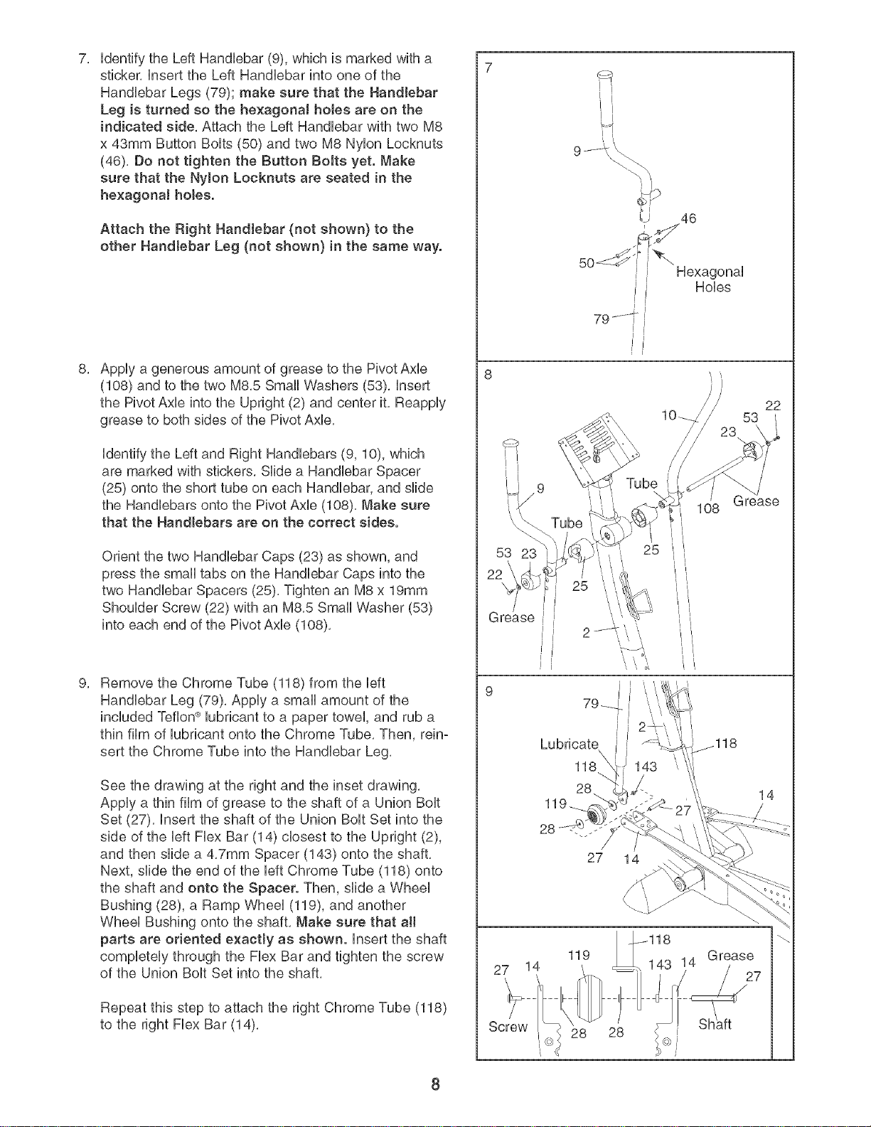
7, 7
identifytheLeftHandlebar(9),whichismarkedwitha
sticker,inserttheLeftHandiebarintooneofthe
HandHebarLegs(79);makesurethattheHandlebar
LegisturnedsothehexagonaJholesareonthe
indicatedside,AttachtheLeftHandiebarwithtwoM8
x43mmButtonBolts(50)andtwoM8NylonLocknuts
(46),DonottightentheButtonBoltsyet.Make
surethattheNylonLocknutsareseatedin the
he×agonaihoJes.
AttachtheRightHandlebar(notshown}tothe
otherHandlebarLeg (not shown} in the same way.
Apply a generous amount of grease to the Pivot Axle
(108) and to the two M8,5 Smali Washers (53), insert
the Pivot Axle into the Upright (2) and center it, Reapply
grease to both sides of the Pivot Axle,
identify the Left and Right Handiebars (9, 10), which
are marked with stickers, SHdea Handiebar Spacer
(25) onto the short tube on each Handiebar, and siide
the Handiebars onto the Pivot Axie (108), Make sure
that the Handlebars are on the correct sides.
Orient the two Handlebar Caps (23) as shown, and
press the small tabs on the Handlebar Caps into the
two Handlebar Spacers (25), Tighten an M8 x 19mm
Shoulder Screw (22) with an M8,5 Small Washer (53)
into each end of the Pivot Axle (108),
Remove the Chrome Tube (118) from the left
Handlebar Leg (79), Apply a small amount of the
included Teflon _ lubricant to a paper towel, and rub a
thin film of lubricant onto the Chrome Tube, Then, rein°
sert the Chrome Tube into the Handlebar Leg,
See the drawing at the right and the inset drawing,
Apply a thin film of grease to the shaft of a Union Bolt
Set (27), insert the shaft of the Union Bolt Set into the
side of the left Flex Bar (14) closest to the Upright (2),
and then slide a 4,7mm Spacer (143) onto the shaft,
Next, slide the end of the left Chrome Tube (118) onto
the shaft and onto the Spacer. Then, slide a Wheel
Bushing (28), a Ramp Wheel (119), and another
Wheel Bushing onto the shaft, Make sure that aH
parts are oriented exactly as shown, insert the shaft
completely through the Flex Bar and tighten the screw
of the Union Bolt Set into the shaft,
Repeat this step to attach the right Chrome Tube (118)
to the right Flex Bar (14),
53
t i
t i
9%
_" 46
Jr Hobs
J f
J f
I
79 j_
J f
J f
9 Tube
/
23
f
Lubricate
53
22
14
8
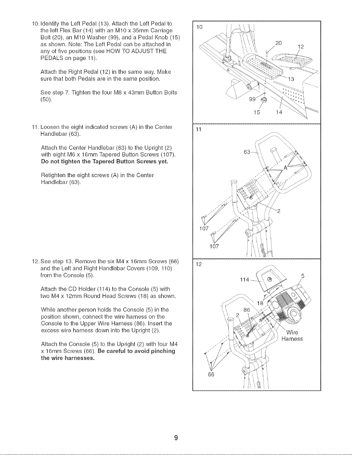
10. identify the Left Pedal (13). Attach the Left Pedal to
the left Flex Bar (14) with an MIO x 35mm Carriage
Bolt (20), an MIO Washer (99), and a Pedal Knob (15)
as shown. Note: The Left Pedal can be attached in
any of five positions (see HOW TO ADJUST THE
PEDALS on page 11).
Attach the Right Pedal (12) in the same way. Make
sure that both Pedals are in the same position.
See step 7. Tighten the four M8 x 43mm Button Bolts
(50).
11. Loosen the eight indicated screws (A) in the Center
Handlebar (63).
Attach the Center Handlebar (63) to the Upright (2)
with eight M6 x 16mm Tapered Sutton Screws (107).
Do not tighten the Tapered Button Screws yet.
Retighten the eight screws (A) in the Center
Handlebar (63).
12.See step 13. Remove the six M4 x 16mm Screws (66)
and the Left and Right Handlebar Covers (109, 110)
from the Console (5).
Attach the CD Holder (114) to the Console (5) with
two M4 x 12mm Round Head Screws (18) as shown.
While another person holds the Console (5) in the
position shown, connect the wire harness on the
Console to the Upper Wire Harness (86). insert the
excess wire harness down into the Upright (2).
Attach the Console (5) to the Upright (2) with four M4
x 16mm Screws (66). Be earefut to avoid pinching
the wire harnesses.
10
11
12
2O
15 14
107
66
12
\
Wire
Harness
9
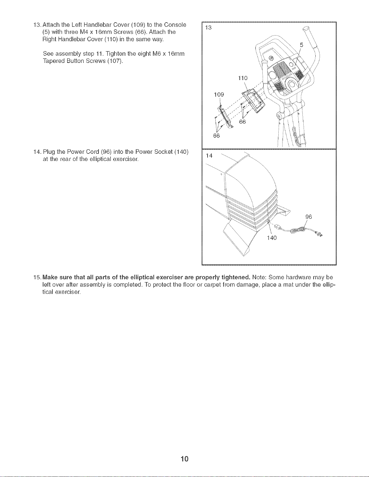
13, Attach the Left HandUebar Cover (109) to the ConsoUe
(5) with three M4 x 16mm Screws (66), Attach the
Right HandUebarCover (110) in the same way,
See assemMy step 11, Tighten the eight M6 x 16mm
Tapered Button Screws (107),
14, Hug the Power Cord (96) into the Power Socket (140)
at the rear of the eHipticaUexerciser,
13
109
66
14
110
66
\
\
_\\\\
\
\
140
96
15, Make sure that aH parts of the elliptical exerciser are properly tightened. Note: Some hardware may be
Ueftover after assemMy is compUeted, To protect the floor or carpet from damage, pUacea mat under the eHipo
ticaUexerciser,
10
HOW TO USE THE ELLiPTiCAL EXERCISER
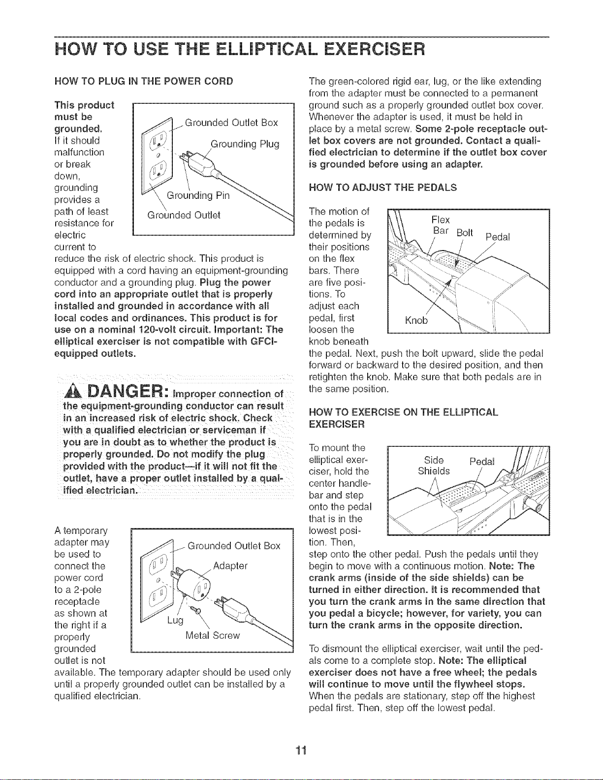
HOW TO PLUG iN THE POWER CORD
This product
must be
grounded.
if it shouUd
maffunction
or break
down,
grounding
provides a
path of bast
resistance for
electric
current to
_rounded Outlet Box
Grounding Hug
/
Grounding Pin
Grounded Outlet
reduce the risk of electric shock, This product is
equipped with a cord having an equipment-grounding
conductor and a grounding plug, Ptug the power
cord into an appropriate outlet that is property
installed and grounded in accordance with all
tocal codes and ordinances. This product is for
use on a nominat 120-volt circuit. Important: The
elliptical exerciser is not compatible with GFCl-
equipped outtets.
A DANGER: Impropereonnect ooof
the equipment-grounding conductor can result
in an increased risk of electric shock. Check
with a quaJified electrician or serviceman if
you are in doubt as to whether the product is
properly grounded. Do not modify the plug
provided with the product--if it will not fit the
outlet, have a proper outlet installed by a qual-
ified eJectrician.
A temporary
adapter may _rounded Outlet Box
be used to
connect the J Adapter
power cord
to a 2-pole
receptacle
as shown at
the right if a Lug \
properly Metal Screw
grounded
outlet is not
available The temporary adapter should be used only
until a properly grounded outlet can be installed by a
qualified electrician,
The green-colored rigid ear, lug, or the like extending
from the adapter must be connected to a permanent
ground such as a properly grounded outlet box cover,
Whenever the adapter is used, it must be held in
place by a metal screw, Some 2-pete receptacJe out-
tet box covers are not grounded. Contact a quail-
fled electrician to determine if the outlet box cover
is grounded before using an adapter.
HOW TO ADJUST THE PEDALS
The motion of
the pedals is Flex
determined by Bar Bolt Pedal
their positions j
on the flex
bars, There
are five posi-
tions, To
adjust each
pedal, first Knob
loosen the
knob beneath
the pedal, Next, push the bolt upward, slide the pedal
forward or backward to the desired position, and then
retighten the knob, Make sure that both pedals are in
the same position,
HOW TO EXERCISE ON THE ELLIPTICAL
EXERCISER
To mount the
elliptical exer-
ciser, hold the
center handle-
bar and step
onto the pedal
that is in the
lowest posi-
tion, Then,
Side Pedal
Shields
step onto the other pedal, Push the pedals until they
begin to move with a continuous motion, Note: The
crank arms (inside of the side shields} can be
turned in either direction. It is recommended that
you turn the crank arms in the same direction that
you pedal a bicycle; however, for variety, you can
turn the crank arms in the opposite direction.
To dismount the elliptical exerciser, wait until the ped-
als come to a complete stop, Note: The eHiptioaJ
exerciser does not have a free wheeJ; the pedaJs
wilt continue to move until the flywheel stops.
When the pedals are stationary, step off the highest
pedal first, Then, step off the lowest pedal,
11
I
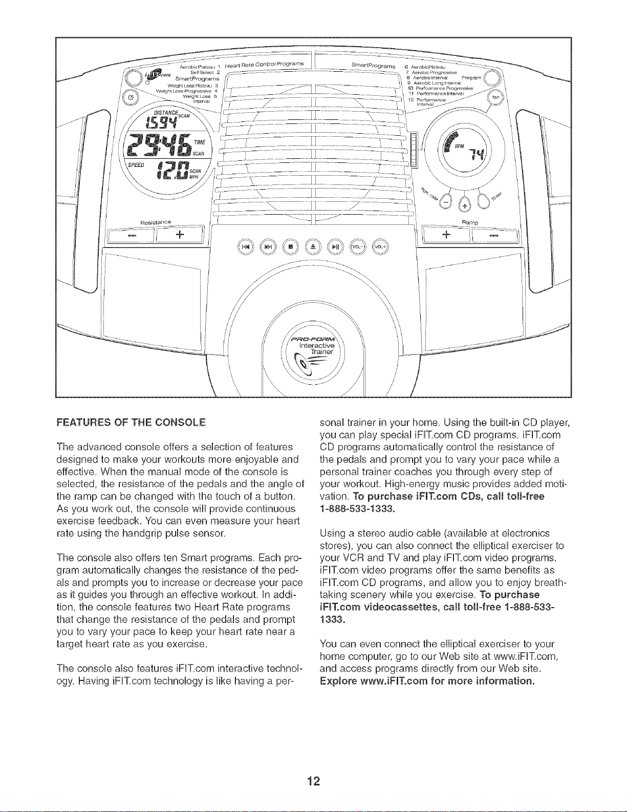
FEATURES OF THE CONSOLE
The advanced console offers a selection of features
designed to make your workouts more enjoyable and
effective, When the manual mode of the console is
selected, the resistance of the pedals and the angle of
the ramp can be changed with the touch of a button,
As you work out, the console win provide continuous
exercise feedback, You can even measure your heart
rate using the handgrip pulse sensor,
The console also offers ten Smart programs, Each pro:
gram automatically changes the resistance of the ped:
als and prompts you to increase or decrease your pace
as it guides you through an effective workout, in addi:
tion, the console features two Heart Rate programs
that change the resistance of the pedals and prompt
you to vary your pace to keep your heart rate near a
target heart rate as you exercise,
The console also features iFIT,com interactive technol:
ogy, Having iFIT,com technology is like having a per:
sonal trainer in your home, Using the built:in CD player,
you can play special iFIT,com CD programs, iFIT,com
CD programs automatically control the resistance of
the pedals and prompt you to vary your pace while a
personal trainer coaches you through every step of
your workout, High:energy music provides added moti:
vation, To purchase iFIT.com CDs, call toll-free
1-888-533-1333.
Using a stereo audio cable (available at electronics
stores), you can also connect the elliptical exerciser to
your VCR and TV and play iFIT,com video programs,
iFIT,com video programs offer the same benefits as
iFIT,com CD programs, and allow you to enjoy breath:
taking scenery while you exercise, To purchase
iFIT,oom videocassettes, call toll-free 1-888-533-
1333,
You can even connect the elliptical exerciser to your
home computer, go to our Web site at www, iFIT,com,
and access programs directly from our Web site,
Explore wwwJFIT.com for more information.
12
To use the manual mode of the console, see the
instructions below, To use a Smart program, see
page 15. To use a Heart Rate program, see page 16.
To use an iFiT.com CD program, see page 18, To
use an iFiT.eom video program, see page 20, To
use a program dkectly from our Web site, see
page 21,
HOW TO USETHEMANUAL MODE
Turn on the console.
Make sure that the power cord is properly plugged
in (see HOW TO PLUG iN THE POWER CORD
on page 11),
To turn on the console, press the On/Reset button
or begin pedaling, (The On/Reset button is the
button just above the large display,)
Select the manua! mode.
Each time the console is
turned on, the manual
mode wiii be selected, if a
program has been select-
ed, reselect the manual
mode by pressing the
Program button repeated-
ly until the letters RPM
appear in the small display,
Change the resistance of the pedals and the
angle of the ramp as desired.
To change the resistance of the pedals, press the
Resistance + and - buttons, There are ten resis-
tance levels; level 10 is the most challenging,
Note: After the buttons are pressed, it will take a
few seconds for the pedals to reach the selected
resistance level,
To vary the feel of your exercise on the elliptical
exerciser, increase or decrease the angle of the
ramp by pressing the Ramp buttons, There are
five ramp angles, Note: After the Ramp buttons
are pressed, it will take a moment for the ramp to
reach the selected angle,
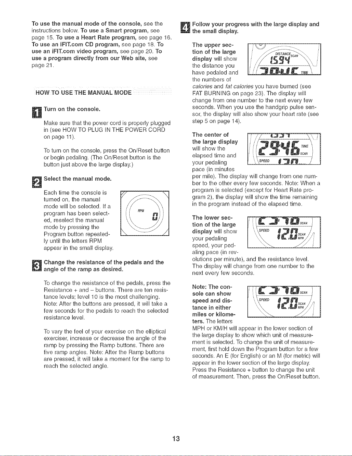
Follow your progress with the large display and
the small display.
The upper sec-
tion of the large
display wiii show
the distance you
have pedaled and
the numbers of
calories and fat calories you have burned (see
FAT BURNING on page 23), The display will
change from one number to the next every few
seconds, When you use the handgrip pulse sen-
sor, the display wili also show your heart rate (see
step 5 on page 14),
The center of
the (arge diep)ay
wiil show the
elapsed time and
your pedaling
pace (in minutes
per mile), The display wiil change from one num-
ber to the other every few seconds, Note: When a
program is selected (except for Heart Rate pro-
gram 2), the display wiil show the time remaining
in the program instead of the elapsed time,
The )ower sec-
tion of the (arge
diep(ay wiii show _PEEa (
your pedaling
speed, your ped-
aling pace (in rev-
olutions per minute), and the resistance level,
The display will change from one number to the
next every few seconds,
Note: The con-
sole can show
speed and dis- _PEE_
tahoe in either
miles or kilome-
ters. The btters
MPH or KM/H wUIappear in the lower section of
the large display to show which unit of measure-
ment is selected, To change the unit of measure-
ment, first hold down the Program button for a few
seconds, An E (for English) or an M (for metric) will
appear in the lower section of the large display,
Press the Resistance + button to change the unit
of measurement, Then, press the On/Reset button,
13

The smaJJ display will
show your pedaling pace
(in revolutions per
minute), The indicator bar
in the small display will
increase or decrease in indicator Bar
length as you increase or
decrease your pedaling
pace, Note: When you use a Heart Rate program,
the small display will show your heart rate instead
of your pedaling pace,
To reset the displays, press the On/Reset button,
Measure your heart rate if desired.
If there are
thin sheets of
pJastic on the
meta! contacts
on the hand-
grip puJse sen-
sor, peeJ off
the plastic. To
use the hand-
grip pulse sen-
sor, hold the
handgrips with your palms resting against the
metal contacts, Avoid moving your hands or
squeezing the handgrips too tightly; exces-
sive movement or pressure may interfere with
heart rate readings. When your pulse is detect-
ed, the heart-shaped indicator in the large display
will flash each time your heart beats, and your
heart rate will be shown,
For the most accurate heart rate reading, continue
to hold the handgrips for about 30 seconds, Note:
When you first hold the handgrips, the large dis-
play will show your heart rate continuously for 30
seconds, The display will then show your heart
rate along with other feedback modes,
Turn on the fan if desired.
To turn on the
fan at low speed,
press the fan
button, To turn
on the fan at
high speed,
press the fan
button a second
time, To turn off
the fan, press the fan button a third time, Note: if
the fan is turned on but the pedals are not moved
for thirty seconds, the fan will automatically turn
off,
Rotate the thumb wheel on the right side of the
fan to pivot the fan to the desired angle,
When you are finished exercising, the console
wilt automatically turn off.
if the pedals are not moved for a few seconds,
the displays wiii pause and the time wiii flash in
the large display, if the pedals are not moved and
the console buttons are not pressed for a few
minutes, the console will turn off,
14
HOWTO USE A SMART PROGRAM
Each Smart program wiii automatically change the
resistance of the pedals and prompt you to increase or
decrease your pace as it guides you through an effec-
tive workout. Programs 3, 4, and 5 are weight loss pro-
grams; programs 6, 7, 8, and 9 are aerobic programs;
and programs 10, 11, and 12 are high-performance
programs.
Follow the steps below to use a Smart program.
Turn on the console.
See step 1 on page 13,
Select one of the Smart programs.
Each time the console is
turned on, the manual
mode wiii be selected. To
select a Smart program,
press the Program button
repeatedly until the num-
ber3,4,5,6,7,8,9,10,
11, or 12 appears in the
small display.
Begin pedaling to start the program.
Each Smart program consists of either 20 or 30
one-minute periods. One resistance level and one
target pace are programmed for each period.
Note: The same resistance level and/or target
pace may be programmed for two or more con-
secutive periods.
When you begin pedaling, the resistance of the
pedals wiii automatically change to the resistance
level programmed for the first period. Note: if the
resistance level is too high or too low, you can
change it by pressing the Resistance buttons.
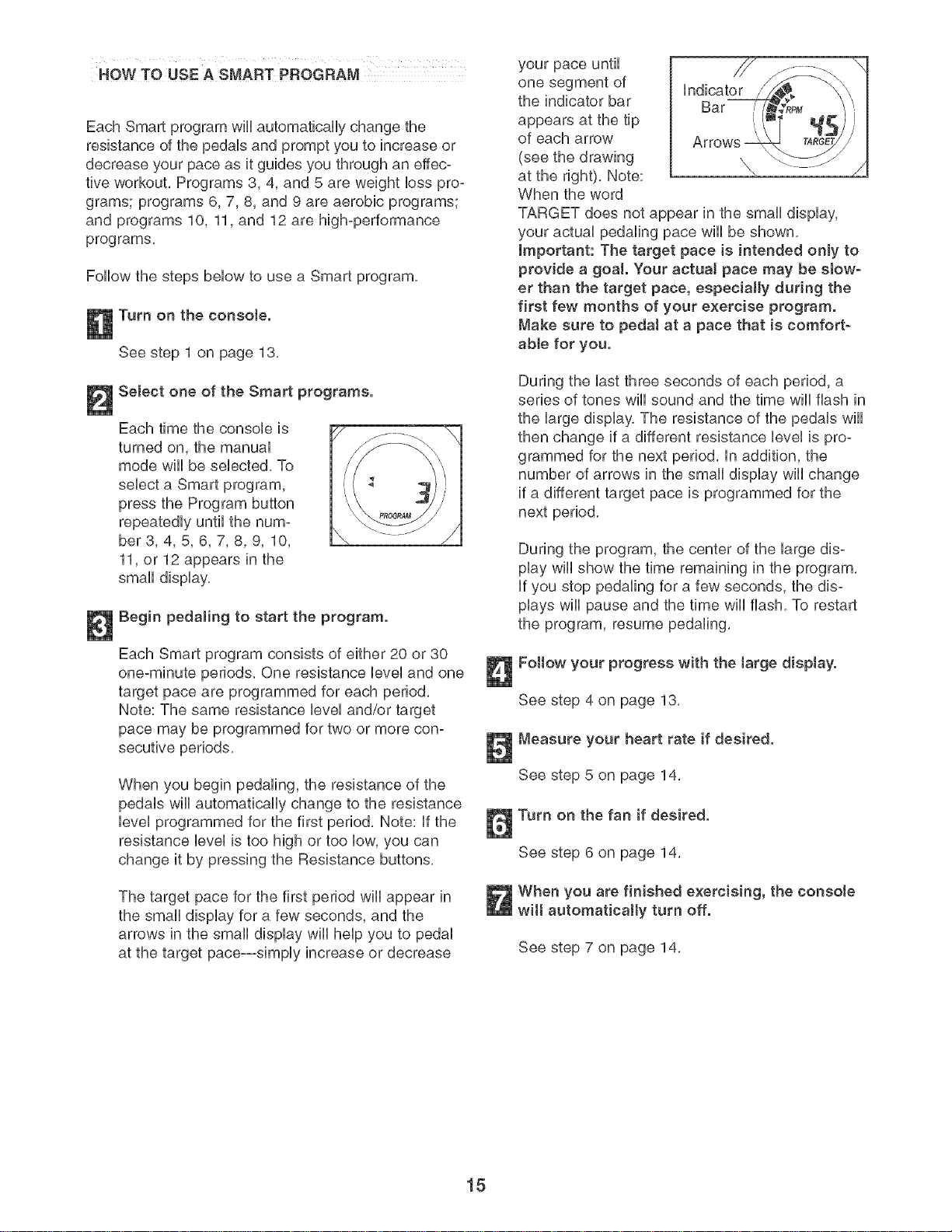
The target pace for the first period wiii appear in
the small display for a few seconds, and the
arrows in the small display will help you to pedal
at the target pace--simply increase or decrease
your pace until _/7
one segment of indicator
the indicator bar Bar
appears at the tip
of each arrow
(see the drawing
at the right). Note:
When the word
TARGET does not appear in the small display,
your actual pedaling pace wiii be shown.
Important: The target pace is intended only to
provide a goal. Your actual pace may be slow-
er than the target pace, especially during the
first few months of your exercise program.
Make sure to peda! at a pace that is comfort-
able for you.
During the last three seconds of each period, a
series of tones will sound and the time will flash in
the large display. The resistance of the pedals will
then change if a different resistance level is pro-
grammed for the next period, in addition, the
number of arrows in the small display will change
if a different target pace is programmed for the
next period.
During the program, the center of the large dis-
play will show the time remaining in the program.
if you stop pedaling for a few seconds, the dis-
plays will pause and the time will flash. To restart
the program, resume pedaling.
Follow your progress with the large display.
See step 4 on page 13,
Measure your heart rate if desired.
See step 5 on page 14,
Turn on the fan if desired.
See step 6 on page 14,
When you are finished exercising, the console
wilt automatically turn off.
See step 7 on page 14,
15
HOWTO USE A HEART RATE PROGRAM
Heart Rate program 1 is designed to keep your heart
rate between 65% and 85% of your maximum heart
rate during your workout, ('Your maximum heart rate is
estimated by subtracting your age from 220, For
exampb, if you are 25 years old, your maximum heart
rate is 195 beats per minute,) Heart Rate program 2 is
designed to keep your heart rate near a target heart
rate that you sebct,
Follow the steps below to use a Heart Rate program,
Turn on the consote.
See step 1 on page 13,
Select one of the Heart Rate programs.
Each time the console is
turned on, the manual
mode wiii be selected. To
select a Heart Rate pro-
gram, press the Program
button repeatedly until the
number 1 or 2 appears in
the small display.
=<
Enter your age or a target heart rate.
if program 1 is selected, the word AGE and the
current age setting wiii appear in the large display,
if you have already entered your age, press the
Enter button, if you have not entered your age,
press the small + and - buttons to enter your age,
and then press the Enter button,
if program 2 is selected, the letters PLS and the
current target heart rate will appear in the large
display, if you do not wish to change the target
heart rate, press the Enter button, if you wish to
change the target heart rate, press the small +
and - buttons, and then press the Enter button,
Hotd the handgdp pulse sensor.
it is not necessary to hold the handgrip pulse
sensor continuously during the program.
However, you should hold the handgrips frequent-
ly for the program to operate properly. Each time
you hotd the handgdps, keep your hands on
the metat contacts for at teast 30 seconds.
Begin pedaling to start the program.
Heart rate program 1 consists of 20 one-minute
periods. One resistance level and one target heart
rate are programmed for each period, (Note: The
same resistance level and/or target heart rate
may be programmed for two or more consecutive
periods,) Heart Rate program 2 is sixty minutes
long (you may choose to use only part of the pro-
gram), The same resistance level and target heart
rate are programmed for the entire program,
When you begin pedaling, the resistance of the
pedals wiii automatically change to the resistance
level programmed for the first period.
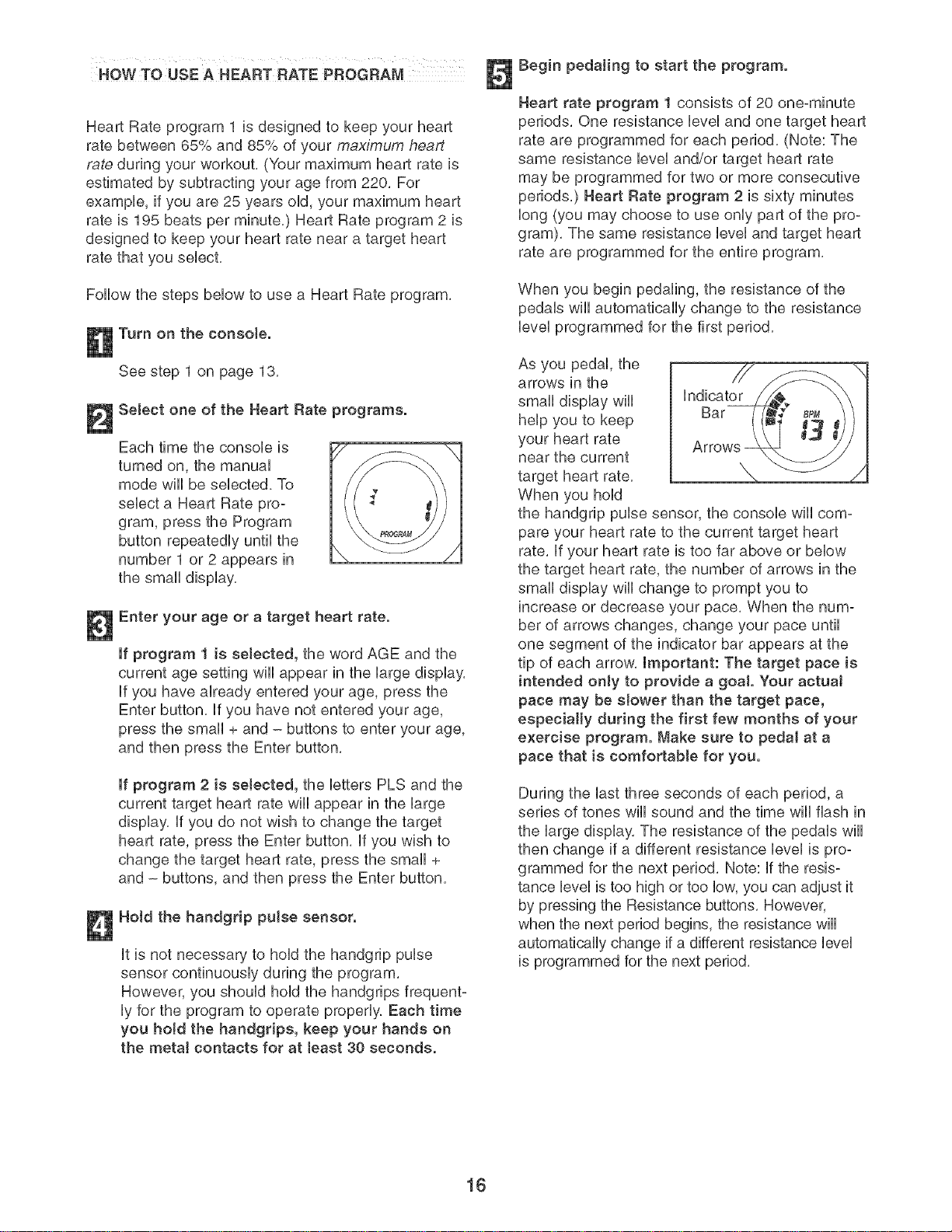
As you pedal, the
arrows in the
small display will indicator
help you to keep Bar
your heart rate Arrows-
near the current
target heart rate.
When you hold
the handgrip pulse sensor, the console will com-
pare your heart rate to the current target heart
rate. if your heart rate is too far above or below
the target heart rate, the number of arrows in the
small display will change to prompt you to
increase or decrease your pace. When the num-
ber of arrows changes, change your pace until
one segment of the indicator bar appears at the
tip of each arrow, important: The target pace is
intended only to provide a goa!. Your actua!
pace may be s!ower than the target pace,
especially during the first few months of your
exercise program. Make sure to pedal at a
pace that is comfortable for you.
During the last three seconds of each period, a
series of tones wiii sound and the time will flash in
the large display. The resistance of the pedals will
then change if a different resistance level is pro-
grammed for the next period. Note: if the resis-
tance level is too high or too low, you can adjust it
by pressing the Resistance buttons. However,
when the next period begins, the resistance will
automatically change if a different resistance level
is programmed for the next period.
16

The program wiii continue in this way until the
large display shows that no time remains in the
program, Note: if you stop pedaling for a few sec-
onds, the program will end, To use the program
again, reselect it and start it at the beginning,
Follow your progress with the large display.
See step 4 on page 13,
Turn on the fan if desired,
See step 6 on page 14,
When you are finished exercising, the console
wilt automatically turn off,
See step 7 on page 14,
17
HOWTO USE JRT.COM CD _ROGRAMS
When you use an iFIT,com CD program, a certified
personal trainer wiii guide you through your workout
while the program interactively controls the resistance
of the pedals and prompts you to increase or
decrease your pace, Note: To purchase iRT.com
CDs, call toil-free 1-888-533-1333.
Follow the steps below to use an iFIT,com CD program,
Turn on the consote.
See step 1 on page 13,
Select the iFIT.com mode.
Each time the console is
turned on, the manual
mode wiii be selected, To
use an iFIT.com CD, press
the iFIT,eom button, The
iFIT,com indicator will light
and the letters iF wiii
appear in the small dis-
play,
Insert an iFIT.com CD into the CD ptayer.
To open the CD
player, slide the
center button on
the CD player
upward,
Carefully
insert an
iFIT,com CD into
the CD player
and then close the lid,
®®®®@@@
Press the Play/Pause button to start the
program.
To start the CD
program, press
the play/pause
button on the
CD player, A
moment after
®®®®@®®
the button is pressed, your personal trainer wiii
begin guiding you through your workout Simply
follow your personal trainer's instructions,
The CD program wiii function in almost the same
way as a Smart program (see step 3 on page 15),
However, an electronic "chirping" sound will alert
you when the resistance level and/or the target
pace is about to change. Note: If the resistance
JeveJand/or the target pace does not change
when a "chirp" is heard, make sure that the
iFIT.com indicator is lit. In addition, adjust the
volume (see step 5 below). If the volume is too
high or too tow, the consoJe may not detect the
program signals.
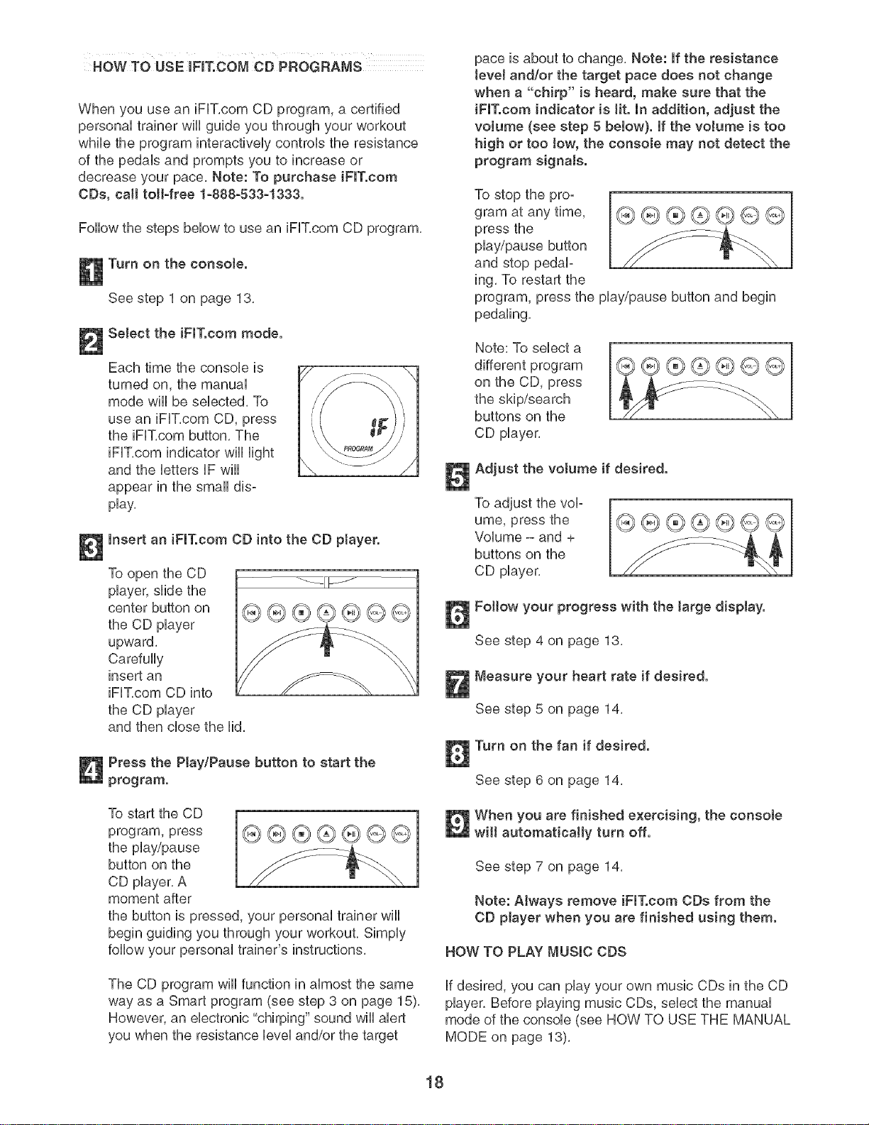
To stop the pro-
gram at any time,
press the
play/pause button
and stop pedal-
ing, To restart the
program, press the play/pause button and begin
pedaling,
Note: To select a
different program
on the CD, press
the skip/search
buttons on the
CD player,
®®®®@®®
Adjust the votume if desired.
To adjust the vol-
ume, press the
Volume - and +
buttons on the
CD player,
®®®®@®®
Fottow your progress with the Jarge display.
See step 4 on page 13,
Measure your heart rate if desired.
See step 5 on page 14,
Turn on the fan if desired.
See step 6 on page 14,
When you are finished exercising, the consote
wilt automatically turn off.
See step 7 on page 14,
Note: AJways remove iFIT.com CDs from the
CD player when you are finished using them.
HOW TO PLAY MUSIC CDS
if desired, you can play your own music CDs in the CD
player. Before playing music CDs, select the manual
mode of the console (see HOW TO USE THE MANUAL
MODE on page 18),
18
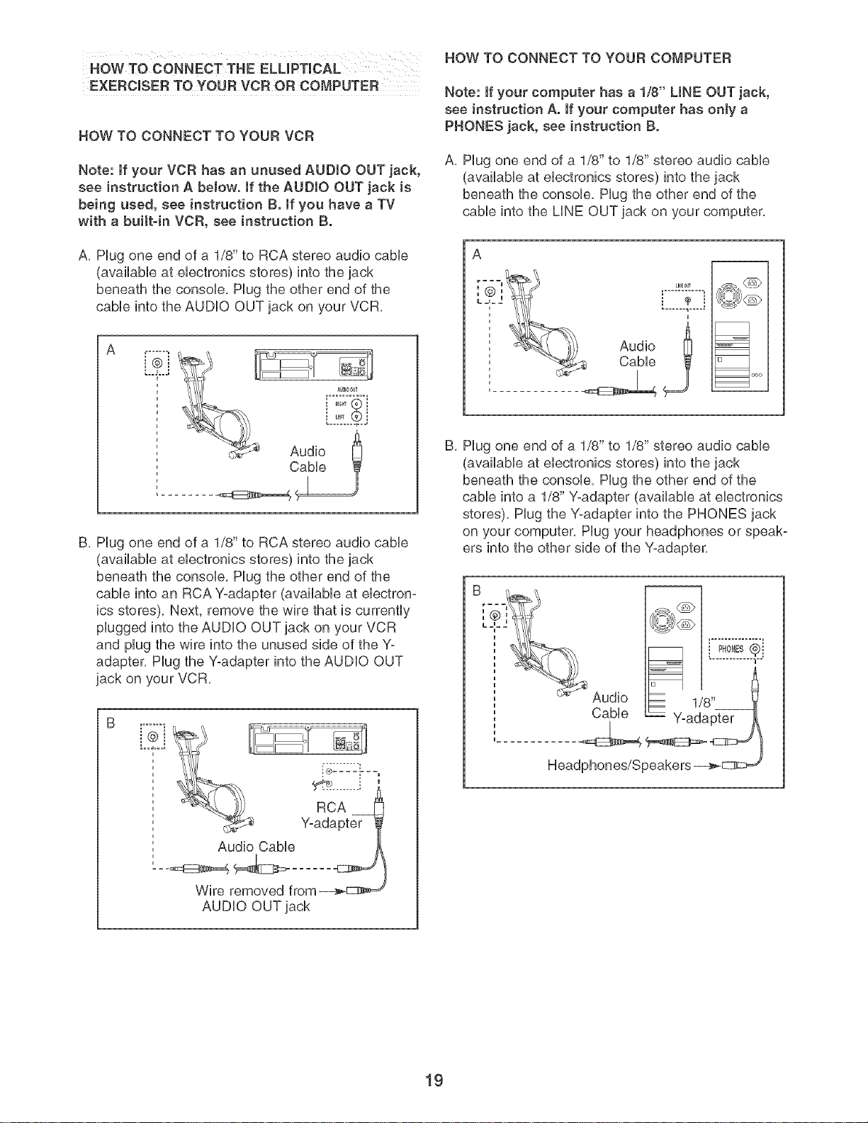
HOW TO CONNECT THE ELUPTmCAL
EXERCmSER TO YOUR VCR OR COMPUTER
HOW TO CONNECT TO YOUR VCR
Note: if your VCR has an unused AUDIO OUT jack,
see instruction A below, if the AUDIO OUT jack is
being used, see instruction B. mfyou have a TV
with a buittqn VCR, see instruction B.
A, Hug one end of a 1/8" to RCA stereo audio cable
(available at electronics stores) into the jack
beneath the console, Hug the other end of the
cable into the AUDIO OUT jack on your VCR,
A
B, Hug one end of a 1/8" to RCA stereo audio cable
(available at electronics stores) into the jack
beneath the console, Hug the other end of the
cane into an RCA Y-adapter (available at electron-
ics stores), Next, remove the wire that is currently
plugged into the AUDIO OUT jack on your VCR
and plug the wire into the unused side of the Y-
adapter, Hug the Y-adapter into the AUDIO OUT
jack on your VCR,
=
Audio Cable
/
Wire removed from_
AUDIO OUT jack
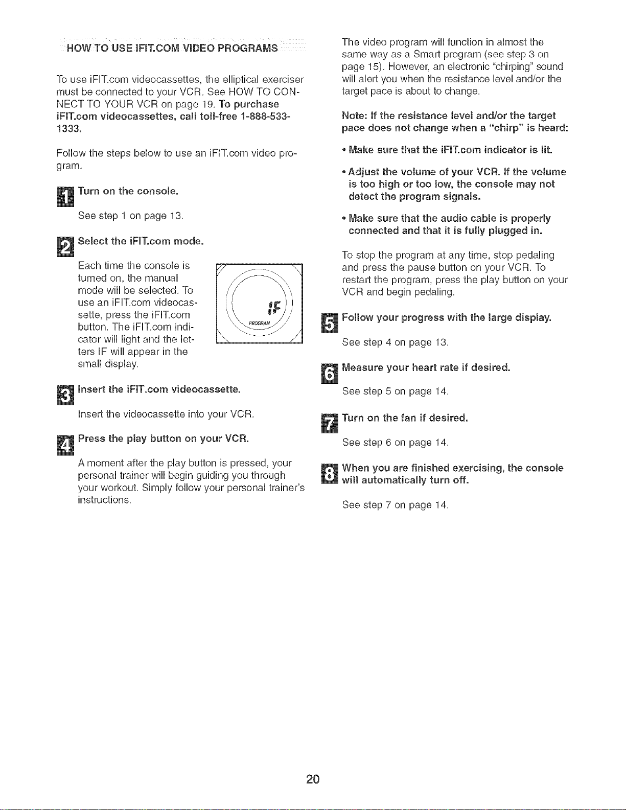
HOW TO CONNECT TO YOUR COMPUTER
Note: If your computer has a 1/8" LINE OUT jack,
see instruction A. If your computer has only a
PHONES jack, see instruction B.
A, Hug one end of a 1/8" to 1/8" stereo audio cable
(available at electronics stores) into the jack
beneath the console, Hug the other end of the
cable into the LiNE OUT jack on your computer,
A
[
,@I
: ' Audio
[ "_ Cable
i
=1
=1 ooo
B, Hug one end of a 1/8" to 1/8" stereo audio cable
(avNlable at electroNcs stores) into the jack
beneath the console, Plug the other end of the
cable into a 1/8" Y-adapter (available at electronics
stores), Plug the Y-adapter into the PHONES jack
on your computer, Plug your headphones or speak-
ers into the other side of the Y-adapter,
Audio
Cable
i pH°"Es®i
u
1/8"
Headphones/Speakers
19
HOW TO USE IFIT.COM VIDEO PROGRAMS
To use iFUT,com videocassettes, the eHiptbaUexerciser
must be connected to your VCR, See HOW TO CON-
NECT TO YOUR VCR on page 19, To purchase
iFIT.com videocassettes, call toll-free 1-888-533-
1333.
Follow the steps bebw to use an iFF, com video pro-
gram,
Turn on the console.
See step 1 on page 13,
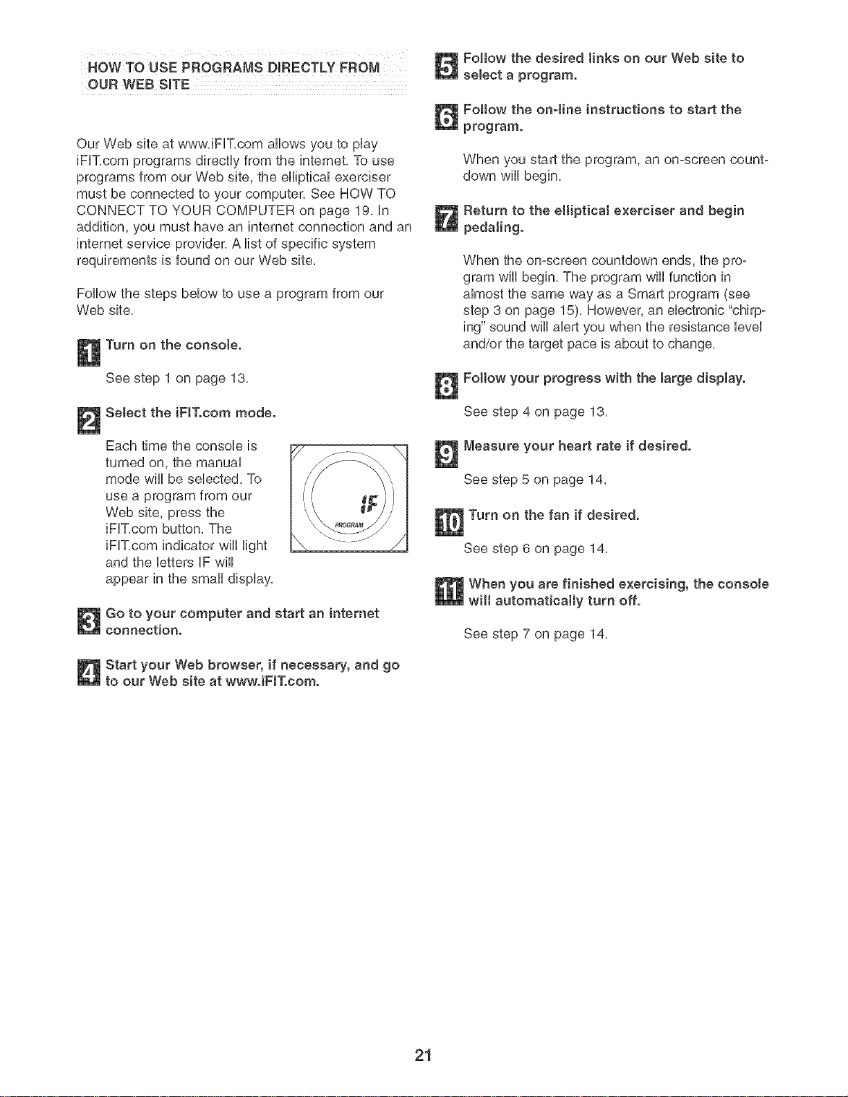
Select the iFIT.com mode.
Each time the consob is
turned on, the manuaU
mode wHUbe sebcted, To
use an iFUT,com videocas-
sette, press the iFUT,com
button, The iFF, com indi-
cator wHUHght and the bt-
ters iF wHUappear in the
small dispUay,
Insert the iFIT.com videocassette.
Insert the videocassette into your VCR,
Press the play button on your VCR.
A moment after the play button is pressed, your
personal trainer wiii begin guiding you through
your workout, Simply follow your personal trainer's
instructions,
The video program wiii function in almost the
same way as a Smart program (see step 3 on
page 15), However, an electronic "chirping" sound
will alert you when the resistance level and/or the
target pace is about to change,
Note: If the resistance leveJ and/or the target
pace does not change when a "chirp" is heard:
Make sure that the iFIT.com indicator is tit.
• Adjust the volume of your VCR. If the volume
is too high or too low, the console may not
detect the program signals.
Make sure that the audio cable is properly
connected and that it is fully plugged in.
To stop the program at any time, stop pedaling
and press the pause button on your VCR, To
restart the program, press the play button on your
VCR and begin pedaling,
Fottow your progress with the targe display.
See step 4 on page 13,
Measure your heart rate if desired.
See step 5 on page 14,
Turn on the fan if desired.
See step 6 on page 14,
When you are finished exercising, the consote
wilt automatically turn off.
See step 7 on page 14,
2O
HOW TO USE PROGRAMS DIRECTLY FROM
OUR WEB StaTE
Our Web site at www, iFIT,com allows you to play
iFUT,com programs directly from the internet, To use
programs from our Web site, the elliptical exerciser
must be connected to your computer, See HOW TO
CONNECT TO YOUR COMPUTER on page 19, in
addition, you must have an internet connection and an
internet service provider, A list of specific system
requirements is found on our Web site,
Follow the steps below to use a program from our
Web site,
Turn on the console.
See step 1 on page 13.
Select the iFIT.com mode.
Each time the console is
turned on, the manual
mode will be selected, To
use a program from our
Web site, press the
iFIT,com button, The
iFIT,com indicator will light
and the letters iF wiii
appear in the small display,
Go to your computer and start an intemet
connection.
Start your Web browser, if necessary, and go
to our Web site at wwwJFIT.com.
Foltow the desired tinke on our Web site to
select a program.
Follow the onqine instructions to start the
program.
When you start the program, an on-screen count-
down will begin.
Return to the ellipticaJ exerciser and begin
pedaling.
When the omscreen countdown ends, the pro-
gram will begin. The program will function in
almost the same way as a Smart program (see
step 3 on page 15). However, an electronic "chirp-
ing" sound will alert you when the resistance level
and/or the target pace is about to change.
Follow your progress with the large display.
See step 4 on page 13.
Measure your heart rate if desired.
See step 5 on page 14.
Turn on the fan if desired.
See step 6 on page 14.
IWhen you are finished exercising, the console
automatically turn off.
See step 7 on page 14.
21
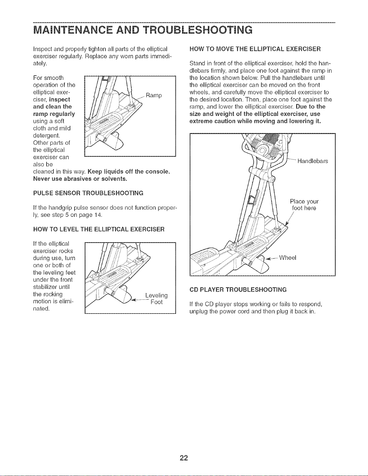
MAINTENANCE AND TROUBLESHOOTmNG
inspect and properUytighten aHparts of the eHipticaU
exerciser reguUarUy,RepUace any worn parts immedi-
ateUy,
For smooth
operation of the
elliptical exer-
ciser, inspect
and clean the
ramp regularly
using a soft
cloth and mild
detergent,
Other parts of
the elliptical
exerciser can
also be
cleaned in this way, Keep tiquids off the console.
Never use abrasives or solvents.
PULSESENSOR TROUBLESHOOTING
if the handgrip pulse sensor does not function proper-
ly, see step 5 on page 14,
HOW TO LEVEL THE ELLIPTICAL EXERCISER
if the elliptical
exerciser rocks
during use, turn
one or both of
the leveling feet
under the front
stabilizer until
the rocking
motion is elimi-
nated,
Leveling
Foot
HOW TO MOVE THE ELLIPTICAL EXERCISER
Stand in front of the elliptical exerciser, hold the han-
dlebars firmly, and place one foot against the ramp in
the location shown below, Pull the handlebars until
the elliptical exerciser can be moved on the front
wheels, and carefully move the elliptical exerciser to
the desired location, Then, place one foot against the
ramp, and lower the elliptical exerciser, Due to the
size and weight of the elliptical exerciser, use
extreme caution while moving and towering it.
Handlebars
Place your
foot here
Wheel
CD PLAYER TROUBLESHOOTING
if the CD player stops working or fails to respond,
unplug the power cord and then plug it back in,
22
CONDmTmONmNGGUmDEUNES
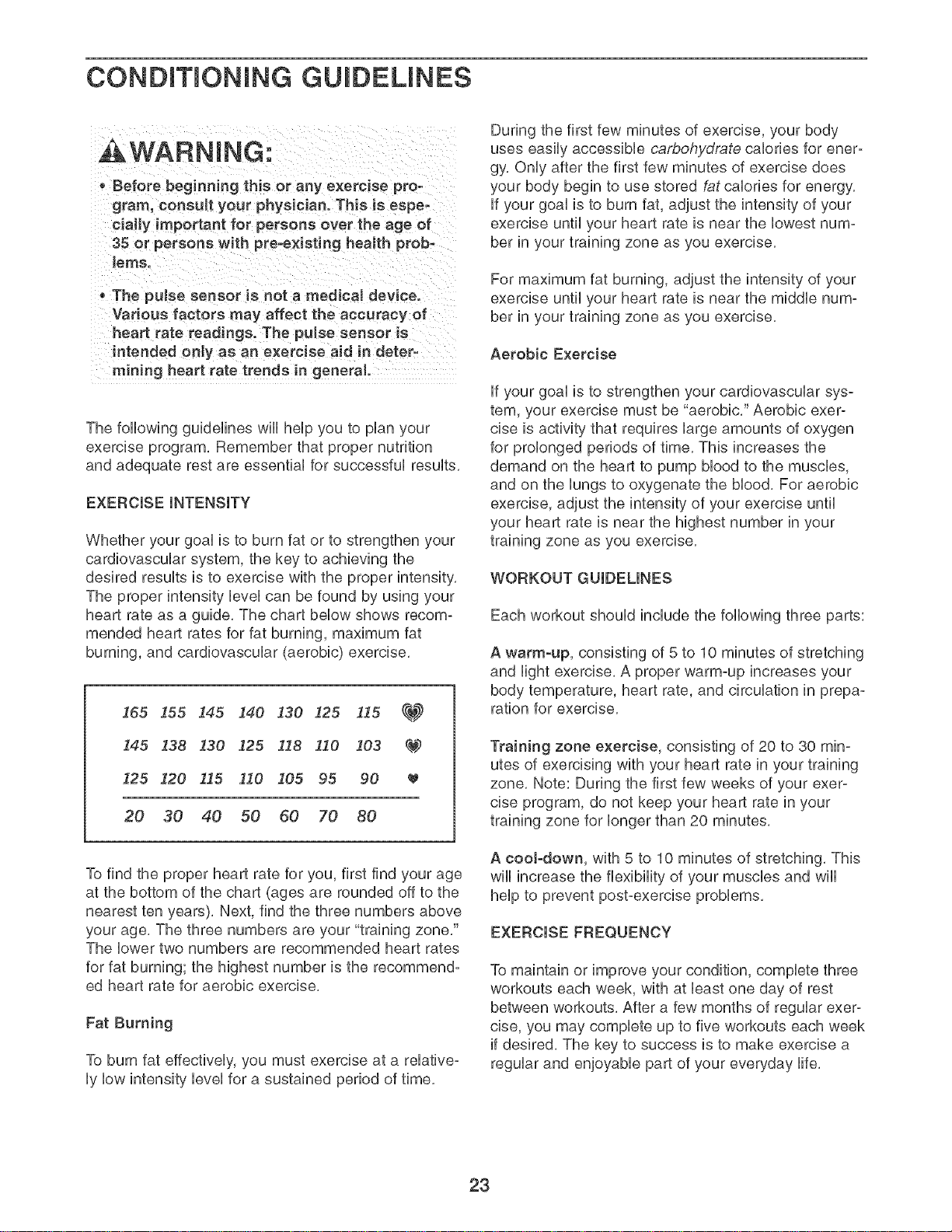
- Before beginning this or any exercise pro-
gram, consult your physician. This is espe-
cially important for persons over the age of
35 or persons with pre-e×isting health prob-
lems.
. The puJse sensor is not a medicaJ device.
Various factors may affect the accuracy of
heart rate readings. The pulse sensor is
intended only as an exercise aid in deter-
mining heart rate trends in general.
The following guidelines wiii help you to plan your
exercise program. Remember that proper nutrition
and adequate rest are essential for successful results.
EXERCISE iNTENSiTY
Whether your goal is to burn fat or to strengthen your
cardiovascular system, the key to achieving the
desired results is to exercise with the proper
The proper intensity level can be found by using your
heart rate as a guide. The chart below shows recom-
mended heart rates for fat burning, maximum fat
burning, and cardiovascular (aerobic) exercise.
165 155 145 140 I30 125 I15 _
145 138 130 125 118 110 103 C_
125 120 115 110 105 95 90
20 30 40 50 60 70 80
To find the proper heart rate for you, first find your age
at the bottom of the chart (ages are rounded off to the
nearest ten years). Next, find the three numbers above
your age. The three numbers are your "training zone."
The lower two numbers are recommended heart rates
for fat burning; the highest number is the recommend-
ed heart rate for aerobic exercise.
Fat Burning
To burn fat effectively, you must exercise at a relative=
ly low intensity level for a sustained period of time.
During the first few minutes of exercise, your body
uses easily accessible ca@ohydt:ate calories for ener-
gy. Only after the first few minutes of exercise does
your body begin to use stored fat calories for energy.
if your goal is to burn fat, adjust the intensity of your
exercise until your heart rate is near the lowest num-
ber in your training zone as you exercise.
For maximum fat burning, adjust the intensity of your
exercise until your heart rate is near the middle num-
ber in your training zone as you exercise.
Aerobic Exercise
if your goal is to strengthen your cardiovascular sys=
tem, your exercise must be "aerobic." Aerobic exer-
cise is activity that requires large amounts of oxygen
for prolonged periods of time. This increases the
demand on the heart to pump blood to the muscles,
and on the lungs to oxygenate the blood. For aerobic
exercise, adjust the intensity of your exercise until
your heart rate is near the highest number in your
training zone as you exercise.
WORKOUT GUiDELiNES
Each workout should include the following three parts:
A warm-up, consisting of 5 to 10 minutes of stretching
and light exercise. A proper warm-up increases your
body temperature, heart rate, and circulation in prepa-
ration for exercise.
Training zone exercise, consisting of 20 to 30 min-
utes of exercising with your heart rate in your training
zone, Note: During the first few weeks of your exer-
cise program, do not keep your heart rate in your
training zone for longer than 20 minutes.
A cooFdown, with 5 to 10 minutes of stretching. This
wili increase the flexibility of your muscles and wili
help to prevent post-exercise problems.
EXERCmSEFREQUENCY
To maintain or improve your condition, complete three
workouts each week, with at bast one day of rest
between workouts. After a few months of regular exer-
cise, you may complete up to five workouts each week
if desired. The key to success is to make exercise a
regular and enjoyable part of your everyday life.
23

PART LiST--Model No. PFEL13031 R0204A
Key No. Qty. Description Key No.
1 1 Frame 53
2 1 Upright 54
3 1 Front Stabilizer 55
4 1 Rear Stabilizer 56
5 1 Consob 57
6 1 Left Side ShbUd 58
7 1 Right Side ShbUd 59
8 1 Rear Left Side ShbUd 60
9 1 Left Handbbar 61
10 1 Right Handbbar 62
11 2 Foam Grip 63
12 1 Right PedaU 64
13 1 Left PedaU 65
14 2 Fbx Bar 66
15 2 PedaUKnob 67
16 1 Left Fbx Bracket 68
17 2 Front Fbx Bracket 69
18 3 M4 x 12mm Round Head Screw 70
19 6 M6 x 26mm Fiat Screw 71
20 2 MIO x 35mm Carriage BoUt 72
21 2 Snap Ring 73
22 2 M8 x 19mm ShouUder Screw 74
23 2 Handbbar Cap 75
24 6 Handbbar Bushing 76
25 2 Handbbar Spacer 77
26 1 Left Handbbar Cover 78
27 2 Union BoUtSet 79
28 4 WheeU Bushing 80
29 1 Right Handbbar Cover 81
30 1 Center Cover 82
31 1 Left Stabilizer Cover 83
32 2 WheeU 84
33 6 M8 x 54mm Button Screw 85
34 1 Left Upright Cover 86
35 1 Left Stabilizer Endcap 87
36 1 Left Crank Arm 88
37 1 Pulley 89
38 1 Right Upright Cover 90
39 1 Crank 91
40 2 Crank Bearing 92
41 1 FUywheeU 93
42 2 FUywheeUBearing 94
43 1 Magnet 95
44 1 Flywheel Axle 96
45 5 M4 x 16mm Round Head Screw 97
46 8 M8 Nylon Locknut 98
47 2 Crank Screw 99
48 1 Right Crank Arm 100
49 1 M6 x 38mm Bolt 101
50 4 M8 x 43mm Button Bolt 102
51 1 M6 x 18mm Bolt 103
52 1 "C" Magnet Bracket 104
Qty.
2
1
1
1
2
4
15
2
4
4
1
4
2
21
6
1
1
2
2
3
3
3
1
1
1
1
2
1
1
1
1
16
1
1
1
2
2
4
1
1
2
10
1
1
1
3
2
2
2
4
1
2
Description
M8,5 Small Washer
"C" Magnet
Motor
Belt
M4 x 5mm Screw
M6 Washer
M6 Nylon Locknut
M6 Nut
M5 Nylon Locknut
M5 x 14mm Bolt
Center Handlebar
M6 x 32mm Button Screw
M8,5 Large Washer
M4 x 16mm Screw
M6 x 18mm Patch Screw
Right Rear Side Shield
Reed Switch Clamp
M8 x 38mm Button Screw
Handlebar Grip
Leveling Foot
M5 x 16mm Screw
M4 x 25mm Round Head Screw
Left Inner Shield
Spring
Reed Switch
Reed Switch Bracket
Handlebar Leg
Side Shield Cover
Right Inner Shield
Right Flex Bracket
Large Frame Spacer
M4 x 12mm Tap Screw
Adjustment Cable Assembly
Upper Wire Harness
Lower Wire Harness
Flex Bracket Spacer
M8 x 25mm Button Screw
Motor Washer
Water Bottle Holder
Right Stabilizer Endcap
M4 x 14mm Round Head Screw
M8 Split Washer
Front Plate
Power Cord
Idler Assembly
M4 x 52mm Screw
MIO Washer
Small Spacer
Large Spacer
M8 x 45ram Button Screw
Alignment Rod
M6 Nut
24

Key No. Qty. Description Key No. Qty. Description
105 1 Idler Bolt 127 2 M8 x 48mm Button Bolt
106 1 Idler Adjustment Screw 128 1 Ramp Axle
107 8 M6 x 16mm Tapered Button Screw 129 2 Frame Bushing
108 1 Pivot Axle 130 2 Ramp Spacer
109 1 Left Handlebar Cover 131 4 Ramp Bushing
110 1 Right Handlebar Cover 132 2 Ramp Axle Cover
111 7 M4 x 14mm Screw 133 1 Ramp
112 2 M6 x 30mm Fiat Bolt 134 1 Ramp Cover
113 1 Rear Hate 135 4 #8 x 9,5ram Screw
114 1 CD Holder 136 1 Control Box Cover
115 2 M8 x 43ram Button Screw 137 1 Incline Axle
116 1 Right Stabilizer Cover 138 1 Left Motor Cover
117 2 Handlebar Leg Bushing 139 1 Right Motor Cover
118 2 Chrome Tube 140 1 Power Socket
119 2 141 1 Control Box
120 1 Incline Motor 142 1 Control Board
121 1 Incline Sensor 143 2 4,7ram Spacer
122 1 Sensor Cover # 6 Allen Wrench
123 2 Incline Spacer # 1 Grease
124 1 Stop Bracket # 1 Teflon _ Lubricant
125 1 Incline Motor Bracket # 1 User's Manual
126 1 Incline Bolt Set
Note: "#" indicates a non-illustrated part, Specifications are subject to change without notice, See the back cover
of this manual for information about ordering replacement parts,
25
22
\
If
107
107
LJ
66
34 24
25
94
143
28
24
38
._-93
24
57
91
,33
94
23
108
24
t i
, ]
118/¢_ i
_, 119
143
74
84
111
1
110
66
66
109
84
J
111'
111
68
114
m
x
0
m
r?'l
¢0
0
¢0
::D
o
PO
o
4_
99
Z9
179
L9
99
96
Og
Z9
kS
_8k

HOW TO ORDER REPLACEMENT PARTS
To order repUacement parts, simpUycall our Customer Service Department toll=free at 1-888-533-1333, Monday
through Friday, 6 a,m, until 6 p,m, Mountain Time (excluding holidays), To heUpus assist you, phase be
prepared to give the following information when calling:
The MODEL NUMBER of the product (PFEL13031)
The NAME of the product (PROFORM _ 1280 S eHiptbaUexerciser)
The SERIAL NUMBER of the product (see the front cover of this manuaU)
The KEY NUMBER and DESCRPTUON of the part(s) (see pages 24 and 25)
LIMITED WARRANTY
iCON HeaUth& Fitness, Unc,(iCON), warrants this product to be free from defects in workmanship and
materiaU, under normaU use and service conditions, for a period of ninety (90) days from the date of pur-
chase, This warranty extends only to the original purchaser, ICON's obligation under this warranty is lim-
ited to replacing or repairing, at ICON's option, the product through one of its authorized service centers,
All repairs for which warranty claims are made must be pre-authorized by ICON, This warranty does not
extend to any product or damage to a product caused by or attributable to freight damage, abuse, mis-
use, improper or abnormal usage or repairs not provided by an ICON authorized service center; products
used for commercial or rental purposes; or products used as store display models, No other warranty
beyond that specifically set forth above is authorized by ICON,
ICON is not responsible or liable for indirect, special or consequential damages arising out of or in con-
nection with the use or performance of the product or damages with respect to any economic loss, loss
of property, loss of revenues or profits, loss of enjoyment or use, costs of removal or installation or other
consequential damages of whatsoever nature, Some states do not allow the exclusion or limitation of inci-
dental or consequential damages, Accordingly, the above limitation may not apply to you,
The warranty extended hereunder is in lieu of any and all other warranties and any implied warranties of
merchantability or fitness for a particular purpose is limited in its scope and duration to the terms set forth
herein, Some states do not allow limitations on how long an implied warranty lasts, Accordingly, the above
limitation may not apply to you,
This warranty gives you specific legal rights, You may also have other rights which va n, from state to state,
ICON HEALTH & FITNESS, INC., 1500 S. 1000 W., LOGAN, UT 84321-9813
Part No, 204428 RO204A Printed in China © 2004 iCON Health & Fitness, Inc,

