Loading ...
Loading ...
Loading ...
13
26D4720
MCUF Series Vent-Free Firebox
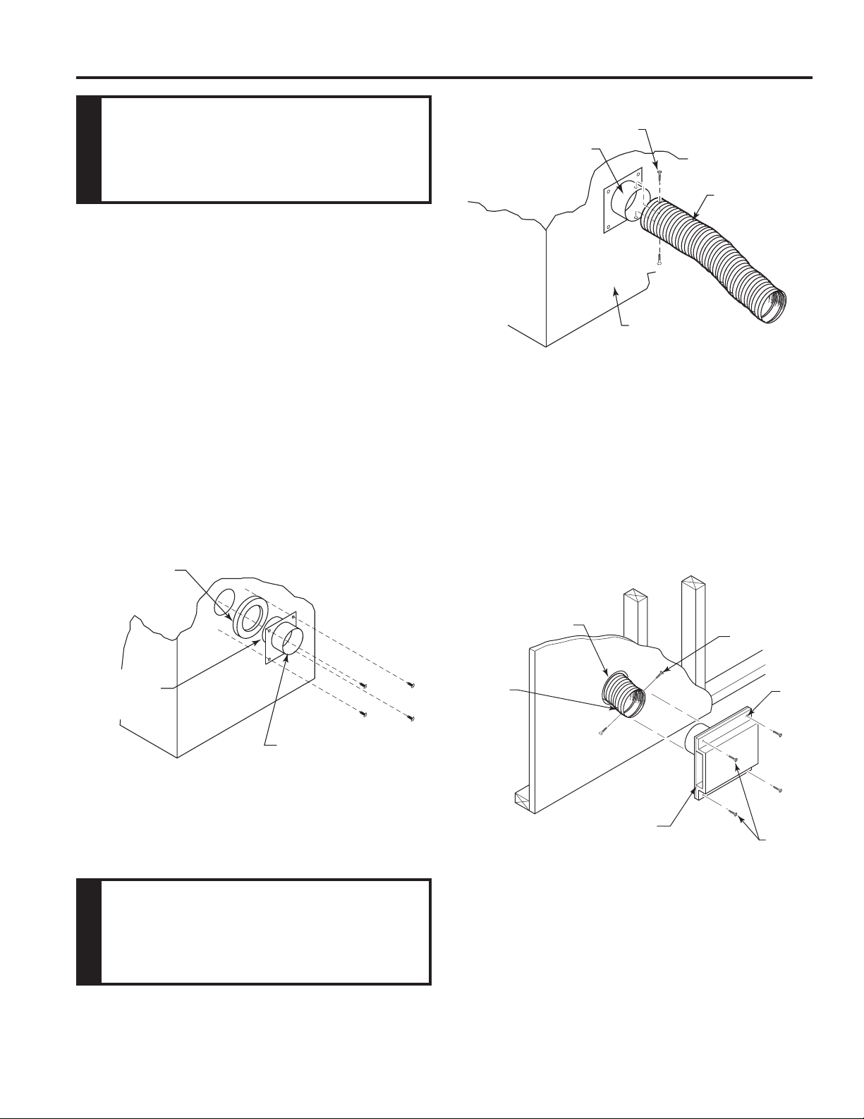
The use of outside air for combustion is optional unless
required by building codes. It is only necessary to supply
outside combustion air to one side of the replace. Use the
model AK4 combustion air kit.
1. Remove the cover plate from the 4" outlet opening loca-
tion on the left or right outside of the replace.
2. Place the insulation ring between the AK-4 starting collar
and replace wall.
3. Place the starting collar (4") into the hole on the side
of replace. Fasten it in place with the four sheet metal
screws provided. Figures 16 and 17
The air starting collar extends through the replace
outer wrap. When the air starting collar is securely attached,
it will form a seal against the replace wall.
4. Attach outside duct to starting collar with duct clamp or
screws. Figure 17
FP1900
OA start collar
8/08
Figure 16 -
Attach Outside Air Starting Collar and Insulation
Ring to Left Side of Fireplace
Insulation
Ring
AK-4 Starting
Collar
Sheet Meal
Screws
Left Side of
Fireplace
Shorter End
of Air Starting
Collar
FP2700
OA duct
Screws
Air Starting
Collar
Duct
Left Side of
Fireplace
FP2700
Figure 17 -
Attach Outside Duct to Starting Collar
FP1904
AK4 install
8/08
6"
Diameter
Hole
Duct
Extending
3" Min.
Screws
Nail
Hole
Screws
AK-4 Inlet
Air Vent
Figure 18 -
Combustion Air Assembly for Model
AK-4
FP1904
5. Cut a 6-inch diameter opening for model AK-4 in the
outside wall covering where the outside vent is to be
located. Figure 18
6. Select and cut a piece of duct long enough to attach to
the replace and stick out at least 3" beyond the face of
the wall to which the AK-4 inlet air vent will be attached.
Figure 17
Loading ...
Loading ...
Loading ...