Loading ...
Loading ...
Loading ...
NOTE: Each full turn of the adjustment
nut will change mower height about 1/8".
• Recheck measurements, adjust if nec-
essary until front tip of blade is 1/8" to
1/2" lower than the rear tip.
• Hold adjustment nut in position with
wrench and tighten jam nut securely
against adjustment nut.
TO REPLACE MOWER DRIVE BELT
MOWER DRIVE BELT REMOVAL
1. Park tractor on a level surface. Engage
parking brake.
2. Lower attachment lift lever to its lowest
position.
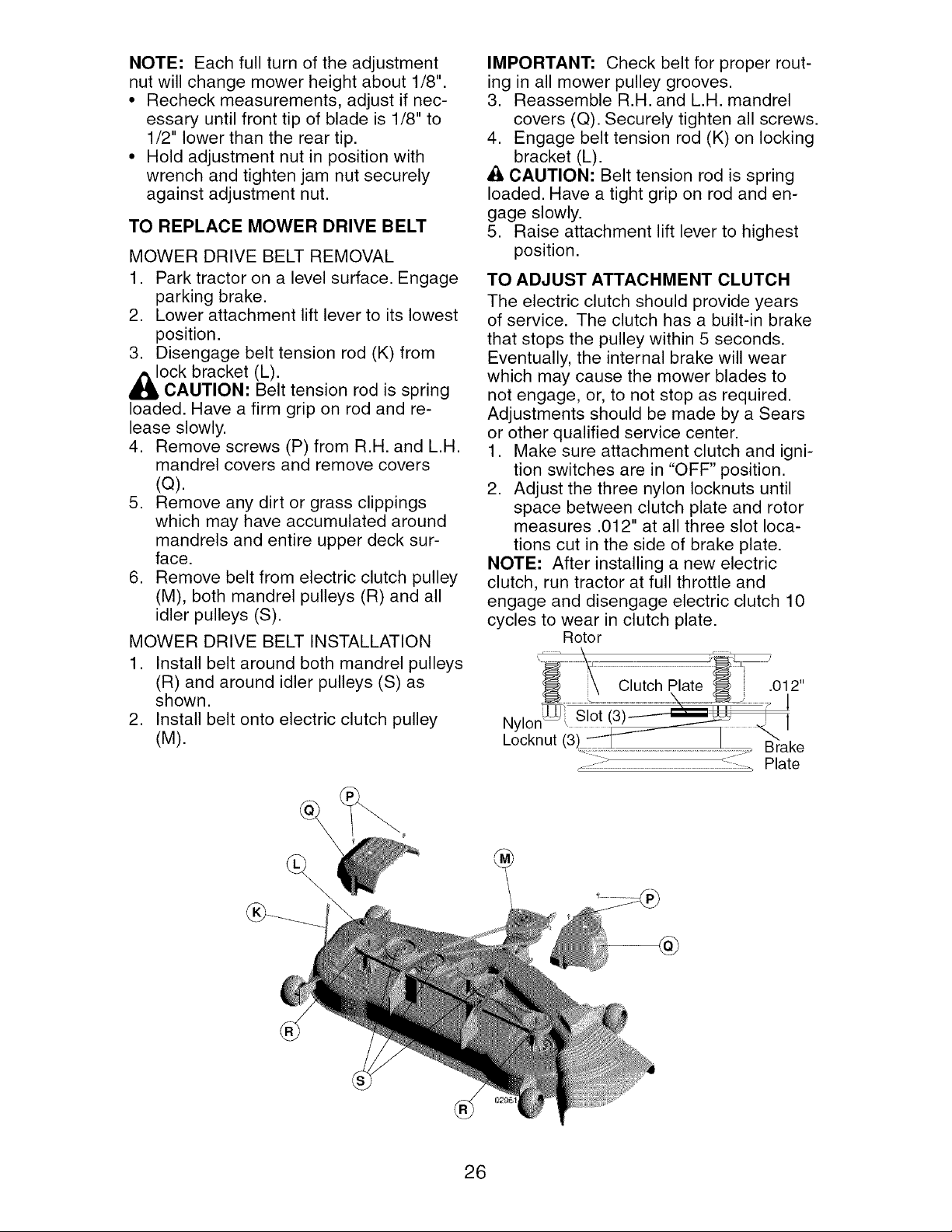
3. Disengage belt tension rod (K) from
_l_OCk bracket (L).
CAUTION: Belt tension rod is spring
loaded. Have a firm grip on rod and re-
lease slowly.
4. Remove screws (P) from R.H. and L.H.
mandrel covers and remove covers
(Q).
5. Remove any dirt or grass clippings
which may have accumulated around
mandrels and entire upper deck sur-
face.
6. Remove belt from electric clutch pulley
(M), both mandrel pulleys (R) and all
idler pulleys (S).
MOWER DRIVE BELT INSTALLATION
1. Install belt around both mandrel pulleys
(R) and around idler pulleys (S) as
shown.
2. Install belt onto electric clutch pulley
(U).
IMPORTANT: Check belt for proper rout-
ing in all mower pulley grooves.
3. Reassemble R.H. and L.H. mandrel
covers (Q). Securely tighten all screws.
4. Engage belt tension rod (K) on locking
bracket (L).
A CAUTION: Belt tension rod is spring
loaded. Have a tight grip on rod and en-
gage slowly.
5. Raise attachment lift lever to highest
position.
TO ADJUST ATTACHMENT CLUTCH
The electric clutch should provide years
of service. The clutch has a built-in brake
that stops the pulley within 5 seconds.
Eventually, the internal brake will wear
which may cause the mower blades to
not engage, or, to not stop as required.
Adjustments should be made by a Sears
or other qualified service center.
1. Make sure attachment clutch and igni-
tion switches are in "OFF" position.
2. Adjust the three nylon Iocknuts until
space between clutch plate and rotor
measures .012" at all three slot loca-
tions cut in the side of brake plate.
NOTE: After installing a new electric
clutch, run tractor at full throttle and
engage and disengage electric clutch 10
cycles to wear in clutch plate.
Rotor
Nylor
Locknut
...................................................................................................._.... Brake
_::::::-_ ::::_ Plate
®
26
Loading ...
Loading ...
Loading ...