Copyright Planika Sp. z o.o. www.planikafires.com IG0110#05 19.02.2019 1
INSTALLATION and USER’S MANUAL
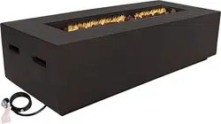
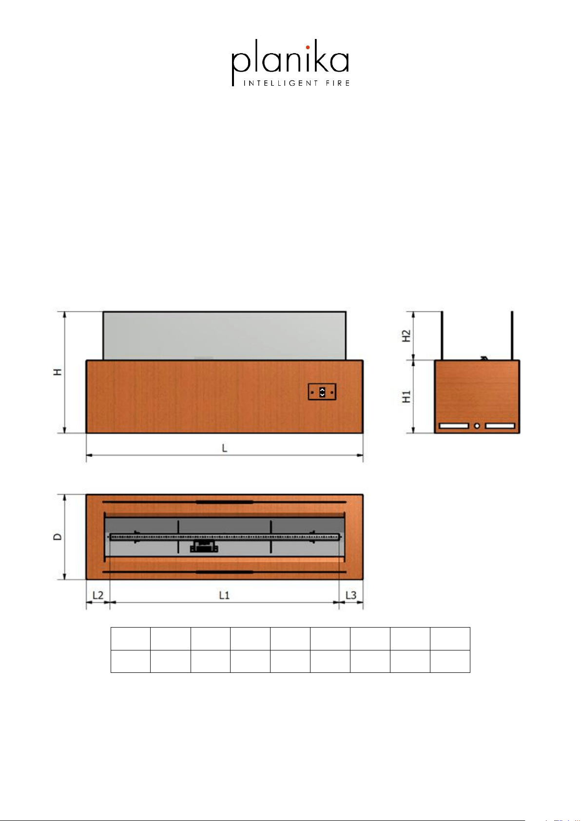
GaLiO Corten
(Natural Gas) (Propane-Butane/Propane)
H H1 H2 L L1 L2 L3 D
[mm] 500 300 200 1140 944 98 98 350
Manufactured by
Planika Sp. z o.o.
Bydgoska 38
86-061 Brzoza
Poland

Copyright Planika Sp. z o.o. www.planikafires.com IG0033#08 2020-03-20 2
IT IS OBLIGATORY TO READ AND KEEP THIS INSTRUCTION MANUAL.
TABLE OF CONTENTS
1. INTRODUCTION ....................................................................................................................................................... 4
2. SAFETY INSTRUCTIONS ............................................................................................................................................ 6
2.1 Safety instruction regarding the use of the gas cylinders. ............................................................................... 7
3. INSTALLATION .......................................................................................................................................................... 7
3.1. Box contents .................................................................................................................................................... 7
3.2. Installation ......................................................................................................... Error! Bookmark not defined.
3.3. Installation of glass screens ........................................................................................................................... 12
3.4. Installation of the gas linkage ........................................................................................................................ 13
3.4.1. Natural gas connection .............................................................................................................................. 13
3.4.2. Connection and replacement of the gas cylinder (LPG version) ................................................................ 13
3.4.3 Regulator replacement (LPG version) ............................................................ Error! Bookmark not defined.
4. OPERATING INSTRUCTIONS ................................................................................................................................... 14
4.1. General Notes ................................................................................................................................................ 14
4.2. Setting up signal code before using the appliance for the first times ........................................................... 14
4.3. Replacing the batteries .................................................................................................................................. 15
4.3.1. Receiver ..................................................................................................................................................... 15
4.3.2. Hand-held transmitter ............................................................................................................................... 18
4.4. Remote control .............................................................................................................................................. 19
4.4.1. Setting Fahrenheit or Celsius ..................................................................................................................... 20
4.4.2. Child Lock ................................................................................................................................................... 20
4.4.3. Setting the Time ......................................................................................................................................... 21
4.4.4. Switch on the Appliance / Igniting the Fire ................................................................................................ 21
4.4.5. Gradually decrease flame height ............................................................................................................... 22
4.4.6. Flame height directly to minimum position ............................................................................................... 23
4.4.7. Gradually increase flame height ................................................................................................................ 23
4.4.8. Flame height directly to maximum position .............................................................................................. 24
4.4.9. Stand-by mode (Pilot flame) ...................................................................................................................... 24
4.4.10. Turning off the device ................................................................................................................................ 25
4.4.11. Countdown Timer ...................................................................................................................................... 25
4.4.12. Automatic Turn Down To Pilot .................................................................................................................. 26
4.4.13. Automatic Shut Off .................................................................................................................................... 26
4.5. Touchpad ....................................................................................................................................................... 27
5. TESTING ................................................................................................................................................................. 28

Copyright Planika Sp. z o.o. www.planikafires.com IG0033#08 2020-03-20 3
5.1 Checking for gas leaks. ................................................................................................................................... 28
5.2 Checking the flame appearance. ................................................................................................................... 28
6. MAINTENANCE AND UPKEEP ................................................................................................................................. 29
6.1. Testing and cleaning ...................................................................................................................................... 29
6.2. Glass cleaning ................................................................................................................................................ 29
7. TROUBLESHOOTING .............................................................................................................................................. 30
8. PRESSURE ADJUSTMENT ........................................................................................................................................ 32
9. ELECTRICAL DIAGRAMS ......................................................................................................................................... 38
10. TECHNICAL SPECIFICATION ................................................................................................................................ 39
11. MANUFACTURER’S CONTACT DETAILS .............................................................................................................. 40

Copyright Planika Sp. z o.o. www.planikafires.com IG0033#08 2020-03-20 4
1. INTRODUCTION
The GaLiO Corten fireplace is a decorative fuel-effect gas appliances intended only for outdoor use. It is obligatory
to acquaint oneself with the below installation manual and user’s manual before committing to the installation and
use of the GaLiO Corten fireplace. This manual is to be kept safe for the lifetime of the device.
The Planika company designs and manufactures gas devices that meet the highest standards of quality, and safety.
The device meets the essential Gas appliances General requirements of the AS/NZS 5263.0:2017 and must be installed
in accordance with AS/NZS 5601.
Each gas fireplace produced by Planika is subjected to factory quality control, during which it undergoes rigorous safety
tests. Materials of the highest quality used for its production guarantee the user a smooth and reliable functioning of
the device.
The device is delivered together with the instruction manual and assembly instructions. The assembly instructions
provide the necessary information to install the device in such a way that it works properly and safely. In addition, you
can find technical data about the device, information on its maintenance and possible failures that may occur, along
with their possible causes and how to resolve them.
WARNING! The installer must be a certified and qualified specialist in gas heating and electricity and should have all
the qualifications required by local law.
CE Declaration of conformity
We hereby declare that both the design and construction of a gas heating device manufactured by Planika Sp. z o.o. (with registered office at
Bydgoska 38, 86-061 Brzoza, Poland) meet the essential requirements contained in the Directive and the Ordinance on gas appliances.
Product: Gas device with decorative combustion effect for outdoor use
Type: Galio Insert, Galio Corten , Galio Corten Remote, Galio Fire Pit Insert , Galio Fire Pit Insert Remote, Galio Fire Pit Corten , Galio Fire Pit
Corten Remote
Standard: AS/NZS 5263.0:2017
The notified body: IAPMO R&T Oceana (7-11 Fullard Road, NARRE WARREN VIC. 3805 AUSTRALIA) has issued the certificate no. GMK10583 for
the above mentioned devices.
The company's quality control system guarantees that the mass-produced devices meet the essential requirements of the applicable Directives
and Regulations as well as the standards contained therein. This Declaration is annulled if any modifications are made to the device without the
prior written consent of Planika.
Brzoza 14.11.2019 Chairman of the Board
Jarosław Dąbrowski

Copyright Planika Sp. z o.o. www.planikafires.com IG0033#08 2020-03-20 5
INSTALLATION NOTICE
• The installation of this appliance is only to be carried out by an authorized person in accordance with the
Manufacturer’s Instructions, local gas fitting regulations, AS/NZS5601.1 installation code for gas burning
appliances and any other relevant statutory regulations.
• In all cases the installation of this appliance shall meet the requirements as set out in AS/NZS5601.1
IMPORTANT SAFETY NOTICES
• DO NOT PLACE ARTICLES ON OR AGAINST THIS APPLIANCE.
• DO NOT USE OR STORE FLAMMABLE MATERIAL NEAR THE APPLIANCE.
• DO NOT SPRAY AEROSOLS IN THE VICINITY OF THIS APPLIANCE WHILST IT IS IN OPERATION.
• DO NOT MODIFY THIS APPLIANCE.
• THIS APPLIANCE IS DESIGNED TO OPERATE WITH LUMINOUS FLAMES. THIS MAY EXHIBIT SLIGHT CARBON
DEPOSITS. THIS IS A NORMAL CONDITION AND IS NOT COVERED BY WARRANTY
• THE GUARD IS FITTED TO THIS APPLIANCE TO REDUCE THE RISK OF FIRE OR INJURY FROM BURNS AND NO
PART OF IT SHOULD BE PERMANENTLY REMOVED. FOR PROTECTION OF YOUNG CHILDREN OR THE INFIRM,
A SECONDARY GUARD IS REQUIRED.
WARNING
This fireplace has a naked flame, care should be taken when it is operating if children or the infirm are in close
proximity. A safety screen is recommended if constant supervision is not possible. It is recommended that a secondary
guard complying with AS-NZS2286 be installed.
The appliance is not intended for use by persons (including children) with reduced physical, sensory or mental
capabilities, or lack of experience and knowledge, unless they have been given supervision or instruction concerning
use of the appliance by a person responsible for their safety. Children should be supervised to ensure that they do not
play with the appliance.
Copyright Planika Sp. z o.o. www.planikafires.com IG0033#08 2020-03-20 6
2. SAFETY INSTRUCTIONS
• Read the instructions before using the appliance.
• Use outdoors only.
• The GaLiO Corten fireplace should be installed and serviced annually according to the below installation
manual as well as enforced national and local laws regarding gas safety (installation and use).
• One needs to assess whether the data on the product plaque complies with the local type of gas and pressure.
• Do not change the structure of the device or its sealed elements nor modify the default settings of the GaLiO
Corten fireplace.
• Do not set any additional imitation blocks nor any glowing coal fragments on the burner or in the combustion
chamber.
• A CO2 or a powder fire extinguisher needs to be placed near the device.
• During the first ignition the GaLiO Corten fireplace needs to be burnt on maximum level for a few hours in
order for the elements to acquire correct temperature and for the remains of paint, lacquer and lubricant to
evaporate.
• The appliance must be fixed in position and not moved.
• GaLiO Corten has been designed for decorative purposes. The surface of the GaLiO Corten fireplace including
the glass screens may get hot (up to 100 degrees Celsius) with the exception of the side walls of the appliance
and the control panel. WARNING!!! Parts of the device that are easy to reach may be very hot. Keep children
away from the device.
• Glass panels must be installed when GaLiO Corten is in use.
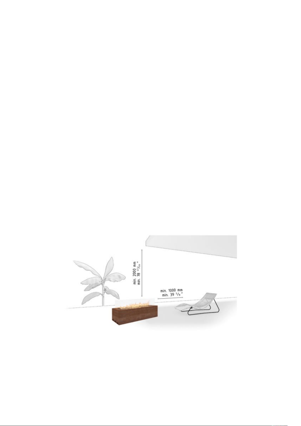
• This appliance must be kept away from flammable materials during use. Do not place any combustible
materials within a distance of 1 m of GaLiO Corten and 2 m over the appliance (Figure 1).
Figure 1: Minimum distance to flammable materials
• When the GaLiO Corten fireplace is on it’s not to be exposed to rain.
• When not being used the GaLiO Corten is to be protected from atmospheric conditions and the main valve of
the gas cylinder needs to be turned off.
• If the GaLiO Corten is not in use for a longer period of time (e.g. winter time), we advise you to protect it with
a cover.

Copyright Planika Sp. z o.o. www.planikafires.com IG0033#08 2020-03-20 7
• Corrosion of the coating of the base of GaLiO Corten is a natural process resulting from the characteristics of
the Corten steel which the fireplace is made of. It is an additional protective layer of the appliance against the
negative influence of unfavorable weather conditions.
• Other parts of the GaLiO Corten fireplace are made of stain resistant material.
• Never leave a turned on GaLiO Corten without supervision.
• The GaLiO Corten fireplace needs to be installed in a place inaccessible for children, unauthorised persons or
animals for the direct contact with the flame or hot parts of the device to be impossible.
• In case of heavy wind the GaLiO Corten fireplace needs to be immediately turned off and one needs to await
until the heavy wind passes.
• In case of noticing any sort of gas leaks the fireplace as well as the main valve of the gas cylinder need to be
turned off.
• After use turn off the gas cylinder valve.
2.1 Safety instruction regarding the use of the gas cylinders.
• Use only the type of gas and pressure specified by the manufacturer.
• The gas cylinders should always be placed in a vertical position – during use and transport.
• Always store the gas cylinder in an easily accessible place to allow its immediate turn-off.
• During the installation process do not allow an open flame or any ignited object to reach the gas cylinder.
• The gas cylinder must be located in accordance with AS/NZS 5601 and AS/NZS 1596.
• Leaks should be found with the use of a cleaning liquid and water. If bubbles form on the surface that means
that there’s a leak that must be fixed before operation.
• Use only approved and certified hose and regulator assemblies, check condition before each use and replace
every 2 years.
• Ensure any hoses are kept away from sharp edges and hot surfaces. Refrain from bends and twists over its full
length.
• Remember that the LPG bottle should be stored in a well-ventilated place. LPG gas is heavier than air and its
accumulation near the bottom surface may generate an explosive mixture.
• The housing in which the LPG bottle is (optionally) placed needs to have an appropriate ventilation. The
housing needs to have upper and lower ventilation (minimum 200cm
2
each, in accordance with AS/NZS
5601.1).
• The gas cylinder needs to be shut if the fireplace is not being used.
• Filling the gas cylinders is to be commissioned to certified gas filling stations.
• Replacement of empty cylinders for full ones is to be conducted only in authorised locations.
3. INSTALLATION
3.1. Box contents
Copyright Planika Sp. z o.o. www.planikafires.com IG0033#08 2020-03-20 8
• 1x complete Galio Corten gas fireplace
• 1x remote control
• 4x Tempered glass guards
• 1x Touch panel (installed)
• 4x AA Batteries
• 2x AAA Batteries
• 4x bag of decorative stones
• 1x AS/NZS 1869 hose assembly – installed (only LPG version)
• 1x pressure regulator– installed (only LPG version)
• 1x installation manual and user’s manual
3.2. Unboxing and installation
• The contents of the boxes need to be carefully unwrapped from the foam foil.
• Remove the bags with decorative stones from the burner reservoir and place them away from it.
• Remove the Styrofoam placed on the unit.
• Carefully lift the appliance and pull out the glass shield wrapped in cardboard from the inside of the GaLiO
Corten.
• Check the completeness of the elements with the contents list.
• Make sure that the device nor its elements weren’t damaged during the transportation (if they were, notify
the supplier).
• Place GaLiO Corten on a flat, paved surface outside of the building, preferably on the place of final installation.
Leave sufficient space on the side of the appliance where control panel is located (minimum 1 m).
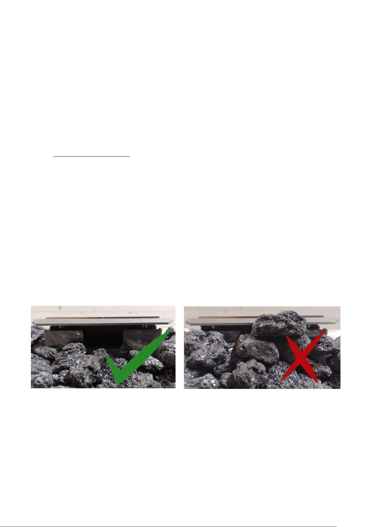
• The decorative stones are to be scattered evenly around the reservoir to completely cover the burner of the
fireplace.
• WARNING!!! The stones may not cover or be placed inside the device protecting the ignition unit (Photo 1).
• It is forbidden to place any other decorative stones which are not supplied by the manufacturer.
• Delivered stones (Silicon Carbide – SiC, content 85%-95%).
Photo 1
• Carefully install the primary glass guards (See point 3.3).
• In the case of GaLiO Corten powered with natural gas, to obtain the optimum image of the flame, cover the
burner with a single layer of decorative stones leaving some spaces uncovered of approximately every 10 cm
(Photo 2).

Copyright Planika Sp. z o.o. www.planikafires.com IG0033#08 2020-03-20 9
Photo 2
• If all the points were completed according to the instruction the gas bottle can be now
connected (See point 3.4.2).
WARNING!!! All elements above the fireplace need to be made of non-flammable materials.
• Select a location where the outdoor fire can be supervised during operation.
• The outdoor fire is suitable for outdoor use only and must not be used indoors.
• An isolation switch must be fitted at the appliance or on an adjacent wall to allow for emergency shutdown
and maintenance.
• Installation must meet Australian gas codes AS/NZS5601.1-2013.
• Do not install under trees or overhanging branches.
• Do not install under eaves, overhang or ceilings.
• Ensure adequate space around the fire to enjoy the flame from a safe distance from the heat and flame.
• Appliance should be covered or protected in wet weather. Not suitable for use in wet or windy weather.
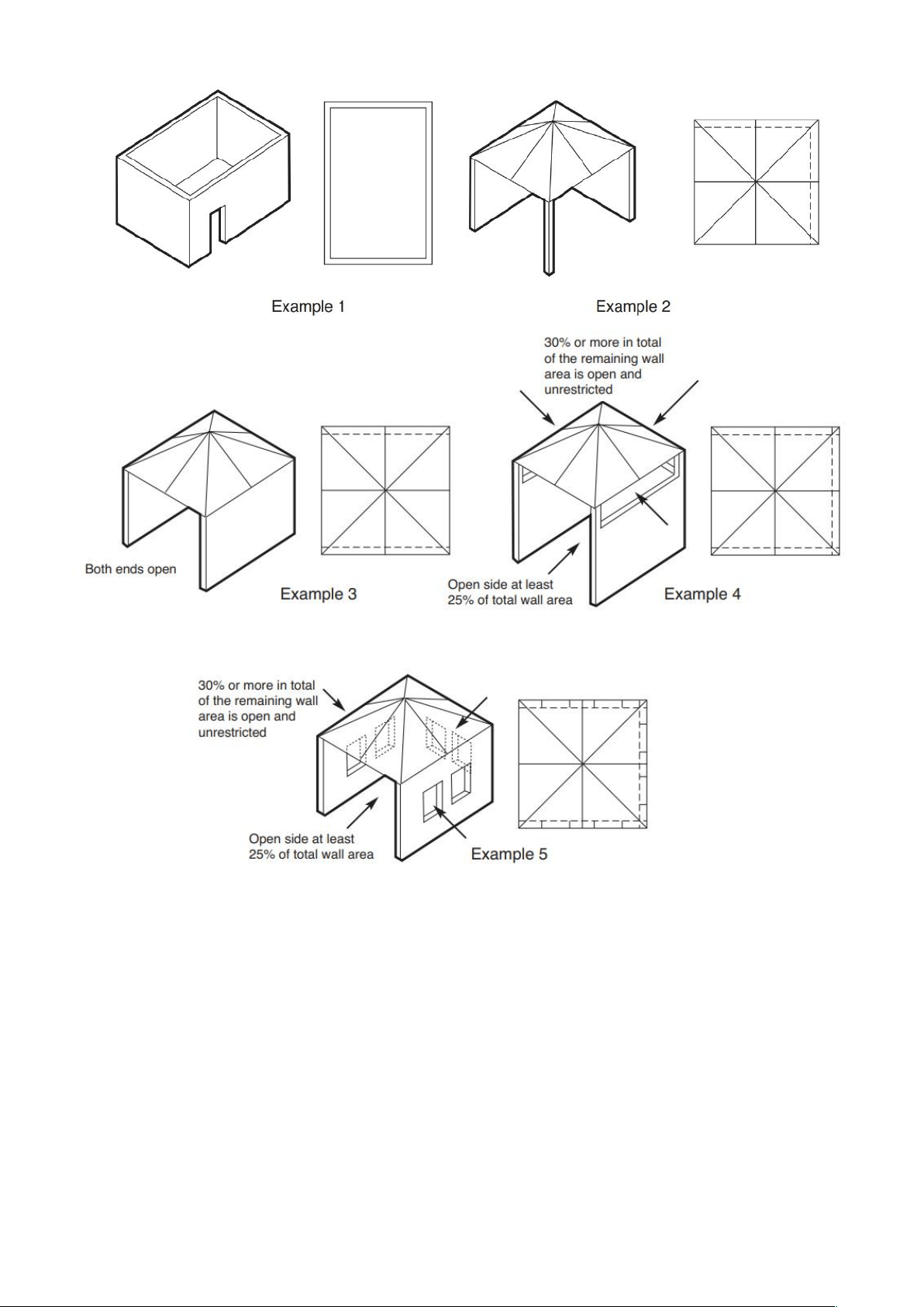
Only use this appliance in an above ground open air situation with natural ventilation, without stagnant areas, where
gas leakage and products of combustion are rapidly dispersed by wind and natural convection.
Any enclosure in which the appliance is used shall comply with the following:
• An enclosure with walls on all sides, but at least one permanent opening at ground level and no overhead
cover.
• Within a partial enclosure that includes an overhead cover and no more than two walls.
• Within a partial enclosure that includes an overhead cover and more than two walls the following shall
apply.
o at least 25% of the total wall area is completely open, and
o at least 30% of the remaining wall area is open and unrestricted
• In the case of balconies, at least 20% of the total wall area shall be and remain open and unrestricted.
• This appliance shall not be used or installed indoors.
• The following figures are diagrammatical representations of outdoor areas
Copyright Planika Sp. z o.o. www.planikafires.com IG0033#08 2020-03-20 10
Gas fire pit minimum height must comply with:
• A gas fire pit with a burner less than 1m above the ground must be guarded to the full height of the flame such
that a child aged between 2 and 6 years of age cannot gain access to the flame when assessed in accordance
with IEC Guide 117.
• A guard incorporated into an appliance to comply with requirement 2 (above) must be an integral part of the
appliance.
Copyright Planika Sp. z o.o. www.planikafires.com IG0033#08 2020-03-20 11
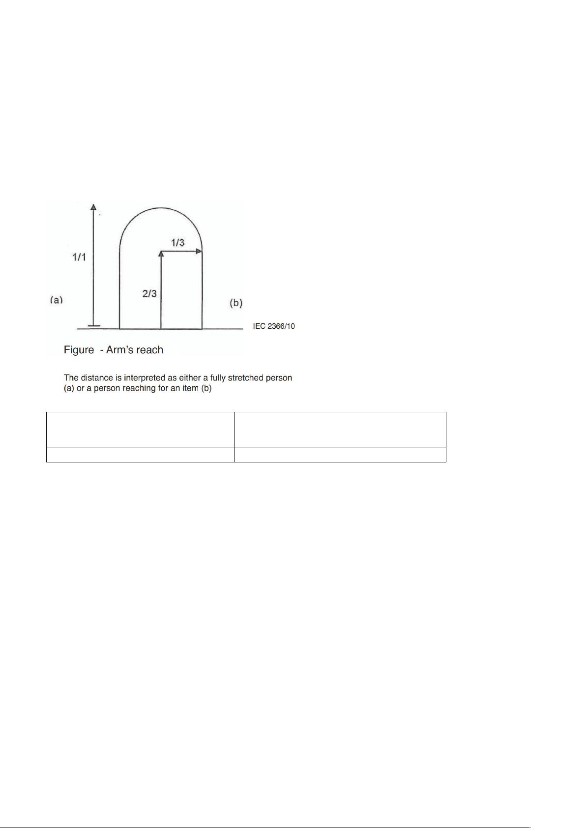
All necessary information concerning the touchable surfaces of the equipment, including the following, shall be
gathered:
• Classification of surface temperatures as hot, moderate or cold
• Material and texture of the surface
• All normal operating conditions of the equipment including the setting that results in maximum temperatures
of the touchable surfaces
• The probability of contact, taking into account the arm’s reach of a person shown in below Figure and Table
Age (Years)
Arm’s reach in the vertical direction
(see (a) of Figure measured from the floor (m)
Children from 2 years to less than 6 years
1,5

Copyright Planika Sp. z o.o. www.planikafires.com IG0033#08 2020-03-20 12
3.3. Installation of glass screens
• Carefully remove cardboard and foam foil from the glass guards.
• Remove all contaminations from the glass guards which could burn out on the glass during operation of the
GaLiO Corten (in particular fingerprints).
• Install glass guards in the corresponding slots on the appliance as shown in Figure 2.
Figure 2
• Remove the glass guards only in case of damage of the glass.

Copyright Planika Sp. z o.o. www.planikafires.com IG0033#08 2020-03-20 13
3.4. Installation of the gas hose
WARNING!!! The installation and service needs to be conducted by a qualified professional, a company or the gas
supplier.
Before proceeding with the connection of the gas cylinder to the fireplace all activity regarding the correct placement
and installation of the GaLiO Corten needs to be already performed. Place the gas linkage away from hot or sharp
edges and make sure it is not twisted.
3.4.1. Natural gas connection
First and foremost, make sure that the connecting device is designed to supply a gas suitable for the type placed in
the gas installation. All necessary information regarding the desired parameters of the gas are found on the rating
plate of the device. Before connecting the gas supply, it is necessary to blow them to remove any remaining metal
filings and other contaminants from inside. Automatic gas control system should be protected from moisture and dust.
These factors may cause irreparable damage to the individual components. The pipe supplying gas to the fireplace
should be equipped with a ball valve with a recommended diameter of 1/2 inch. The individual elements of the gas
installation cannot be sealed using Teflon tape or PTFE tape.
The gas valve on the gas pipe must be installed in accordance with applicable national regulations. Before connecting
the gas, make sure that the gas pipes and connections have no dirt. Gas connection is finished with external thread
3/8 ". Regarding gas connection, the following requirements shall apply:
• You must use the gas pipe with the correct dimensions, so there is no pressure loss.
• Ball gas valve should be installed in an easily accessible place and have the necessary CE mark.
3.4.2. Connection and replacement of the gas cylinder (LPG version)
The GaLiO Corten is delivered together with an AS/NZS 1869 certified hose assembly which, on one end is connected
to the valve of the appliance and on the other end to the AS 4621 certified 2.75kParegulator (POL connection) ready
to be connected to the gas cylinder. The hose and regulator assembly must be checked at each time a new cylinder is
connected, for any damage or deterioration such as cracks, cuts, abrasions including the condition of the o-ring seal.
If in any doubt contact the place of purchase for a suitable replacement.
The GaLiO Corten fireplace is suitable for use with 4.5kg-9kg propane cylinders.
WARNING!!! NEVER use an unstable gas connection or a regulator for other gas pressure.
Copyright Planika Sp. z o.o. www.planikafires.com IG0033#08 2020-03-20 14
4. OPERATING INSTRUCTIONS
4.1. General Notes
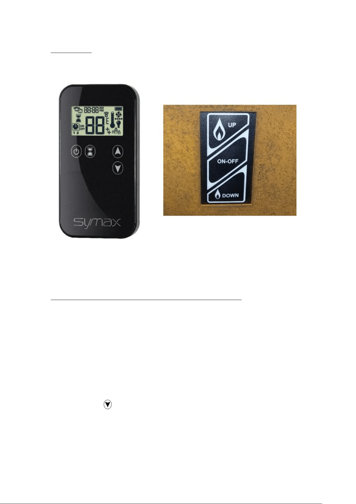
The GaLiO Corten Remote fireplace has a remotely control valve with a built-in ignition for the pilot flame. The flame
height of the main burner may be appropriately regulated by remote control or Touch Panel.
Photo 3: Hand-held transmitter and Touch Panel
4.2. Setting up signal code before using the appliance for the first times
WARNING! You only need to set up the signal code once. It is not necessary when changing the batteries of the hand-
held transmitter or receiver. The appliance is delivered already configured and ready to work.
In case of lost or damaged of hand-held transmitter the new one has to be programmed and the receiver must first
learn the hand-held transmitter’s signal code before the first use:
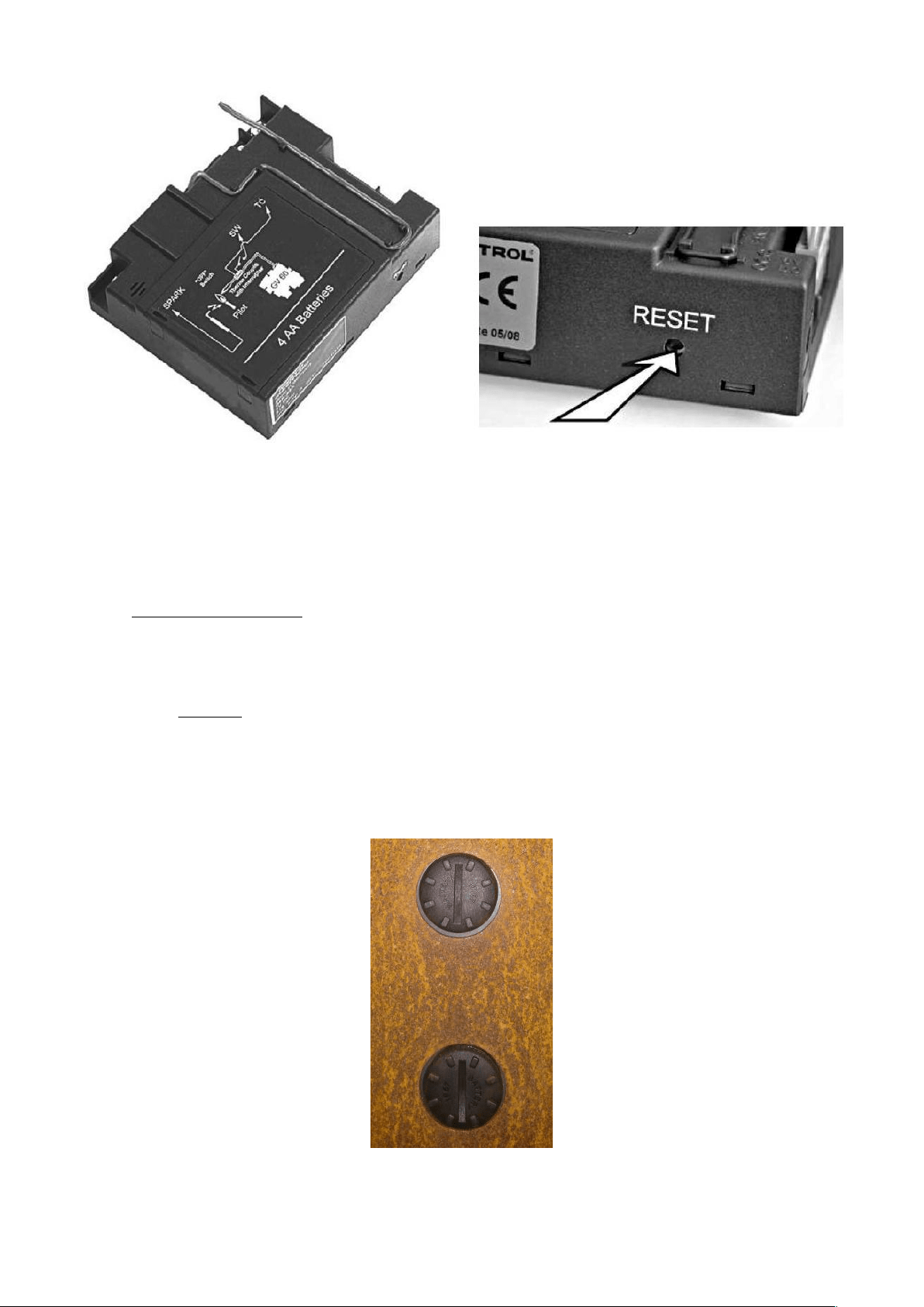
• Press the “RESET” button on the receiver, and keep this pressed until 2 beeps are heard (See Figure 2). Release
the “RESET” button after the second (somewhat longer) beep.
Press, within 20 seconds, the button (small flame) on the hand-held transmitter, until 2 short beeps are heard.
The signal code has now been set up on the receiver. If, however, a single long beep is heard, this means that setting
the signal code has failed or that the wiring has been connected incorrectly.
Copyright Planika Sp. z o.o. www.planikafires.com IG0033#08 2020-03-20 15
Photo 4: Receiver “RESET” button
4.3. Replacing the batteries
If the batteries are inserted incorrectly, the electronics or drive may be irreparably damaged. Only replace the batteries
when the appliance has been completely switched off.
4.3.1. Receiver
NOTE: If the appliance is equipped with a 230 VAC connection, no batteries are present in the receiver.
The batteries are placed in two containers (2 batteries in each container) located at the bottom of Galio Fire Pit Corten.
(See Photo 5).
Photo 5: Receiver batteries containers
Copyright Planika Sp. z o.o. www.planikafires.com IG0033#08 2020-03-20 16
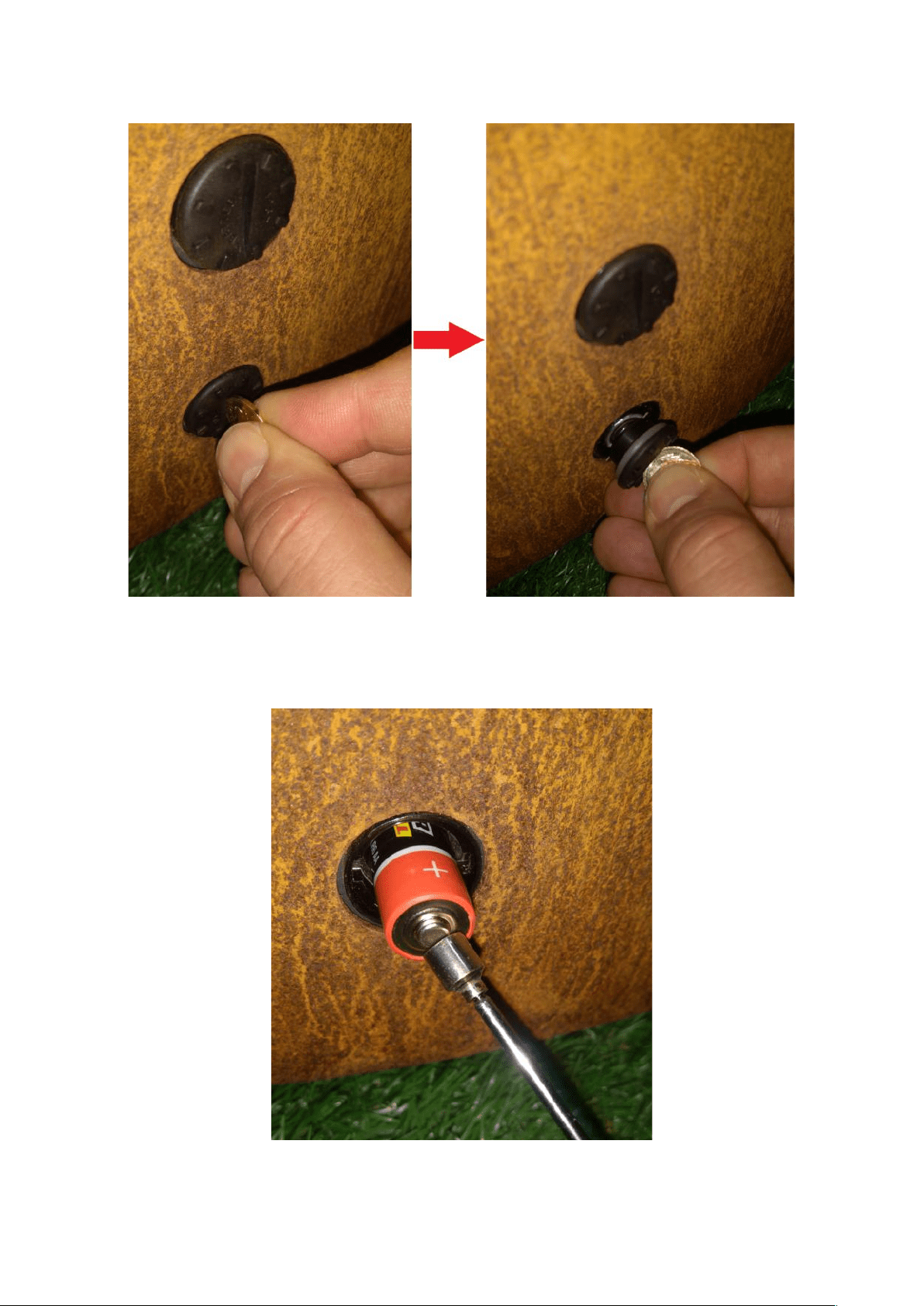
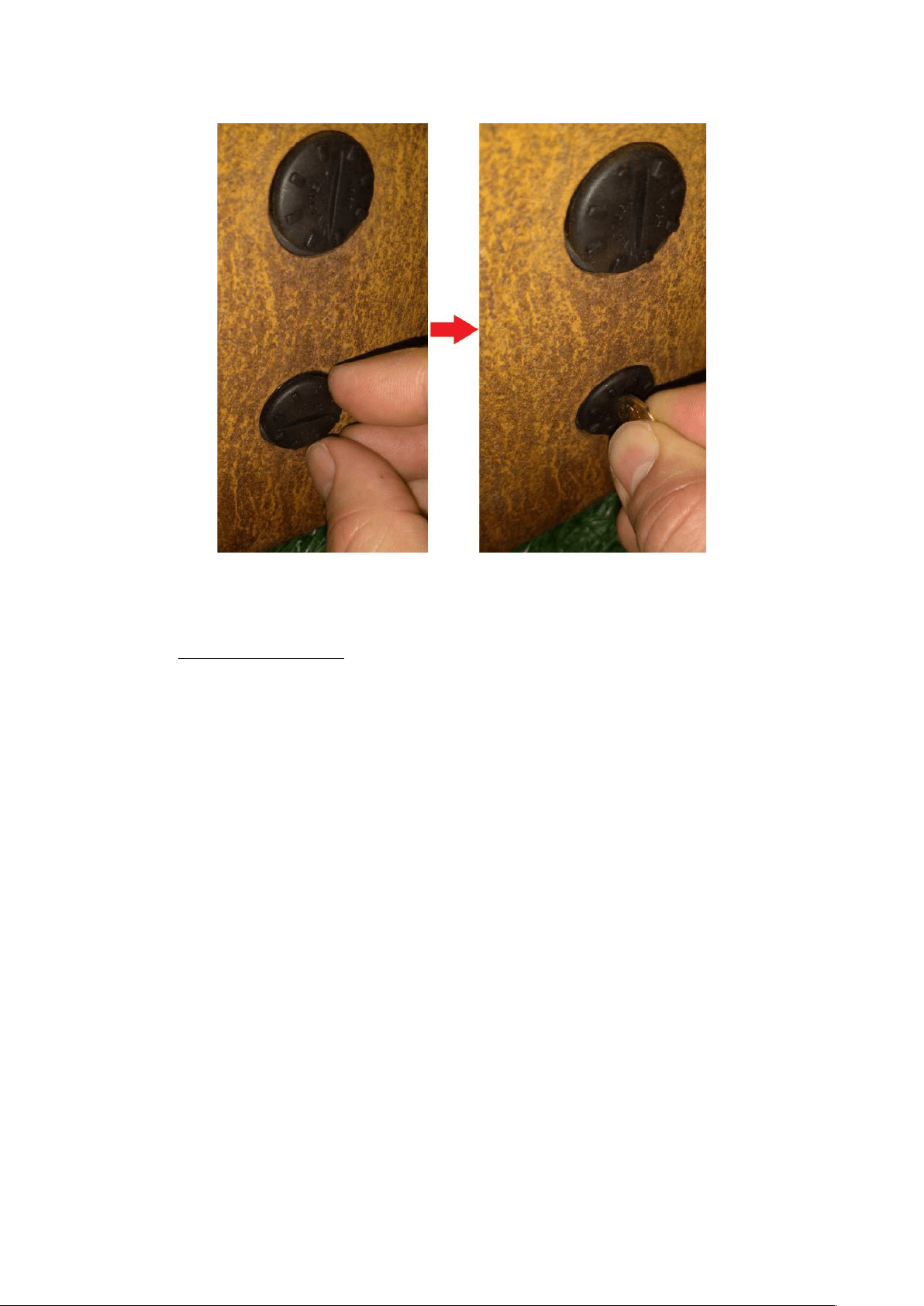
• Unscrew the cover of the first battery container with a wide screwdriver or a coin.
Photo 6: Cover of the batteries container
• Using the magnetic gripper (delivered together with the device), remove the first battery from the container.
Photo 7: Removing the first battery using the magnetic gripper
Copyright Planika Sp. z o.o. www.planikafires.com IG0033#08 2020-03-20 17
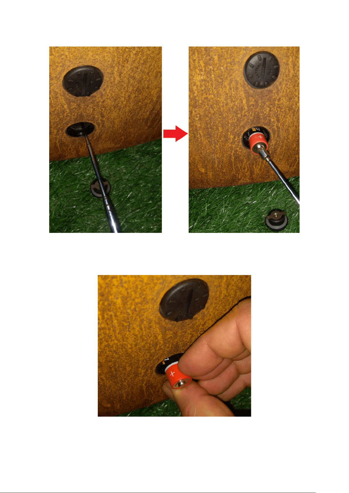
• To remove the second battery, insert the magnetic gripper into the battery container.
Photo 8: Removing the second battery from the container
• Place the new batteries into the container. WARNING! Remember about proper polarization of the batteries.
Photo 9: Placing the battery in the container
Copyright Planika Sp. z o.o. www.planikafires.com IG0033#08 2020-03-20 18
• Screw the cover of the batteries container.
• Repeat the same procedure for changing the batteries in the second container.
4.3.2. Hand-held transmitter
The hand-held transmitter batteries have a service life of approx. one year. We recommend you use alkaline batteries.
Rechargeable batteries are not permitted. Replacement of the batteries is necessary when the battery symbol
indicates this in the display.
: Battery fully charged
: Battery empty
• Open the cover on the back of the transmitter.
• Remove the batteries from the battery compartment.
• Place two new 1.5V batteries (LR03 or AAA type) as indicated in the battery compartment.
• Close the cover.
Copyright Planika Sp. z o.o. www.planikafires.com IG0033#08 2020-03-20 19
4.4. Remote control
GaLiO Corten Remote is operated by radio remote control. This comprises a hand-held transmitter and a receiver.
The receiver is part of the gas control block assembly.
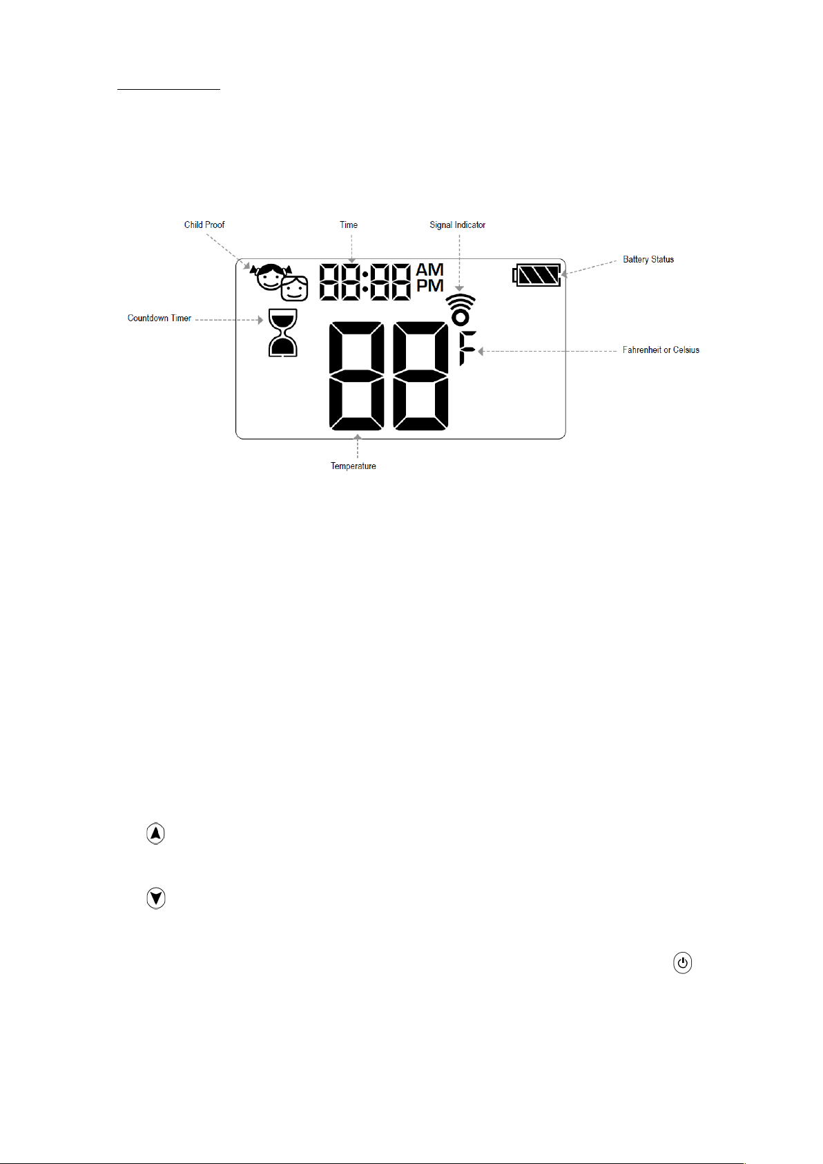
Figure 5: Display hand-held transmitter
• Electrical connections and batteries:
o Hand-held transmitter: 2x 1.5V AAA battery
o Receiver: 4x1.5V AA battery or 6 VDC
• WARNING! Without using a mains adapter, battery replacement is recommended at the beginning of each
heating season. Old or dead batteries should be removed immediately. If left in the unit the batteries can
overheat, leak, and / or explode. Do NOT expose batteries (including during storage) to direct sunlight,
excessive heat, fire, moisture, or severe impact. Each of these conditions can cause the batteries to overheat,
leak, and / or explode. Batteries must be kept within their recommended temperature limits. Ambient battery
temperature range: 32 °F to 131 °F[0 °C to 55 °C].
Software Version
Press and buttons simultaneously. Software version is displayed.
Handset Model Number
Press and buttons simultaneously. Handset model number is displayed.
Handset One Button and Two Button Ignition
Change from one button to two button ignition (Default Setting) or vice versa by pressing and holding button for
10 sec. immediately after installing batteries. ON is displayed and 1 or 2 (one or two button ignition) is flashing. When
change is complete 1 changes to 2 or vice versa.
Copyright Planika Sp. z o.o. www.planikafires.com IG0033#08 2020-03-20 20
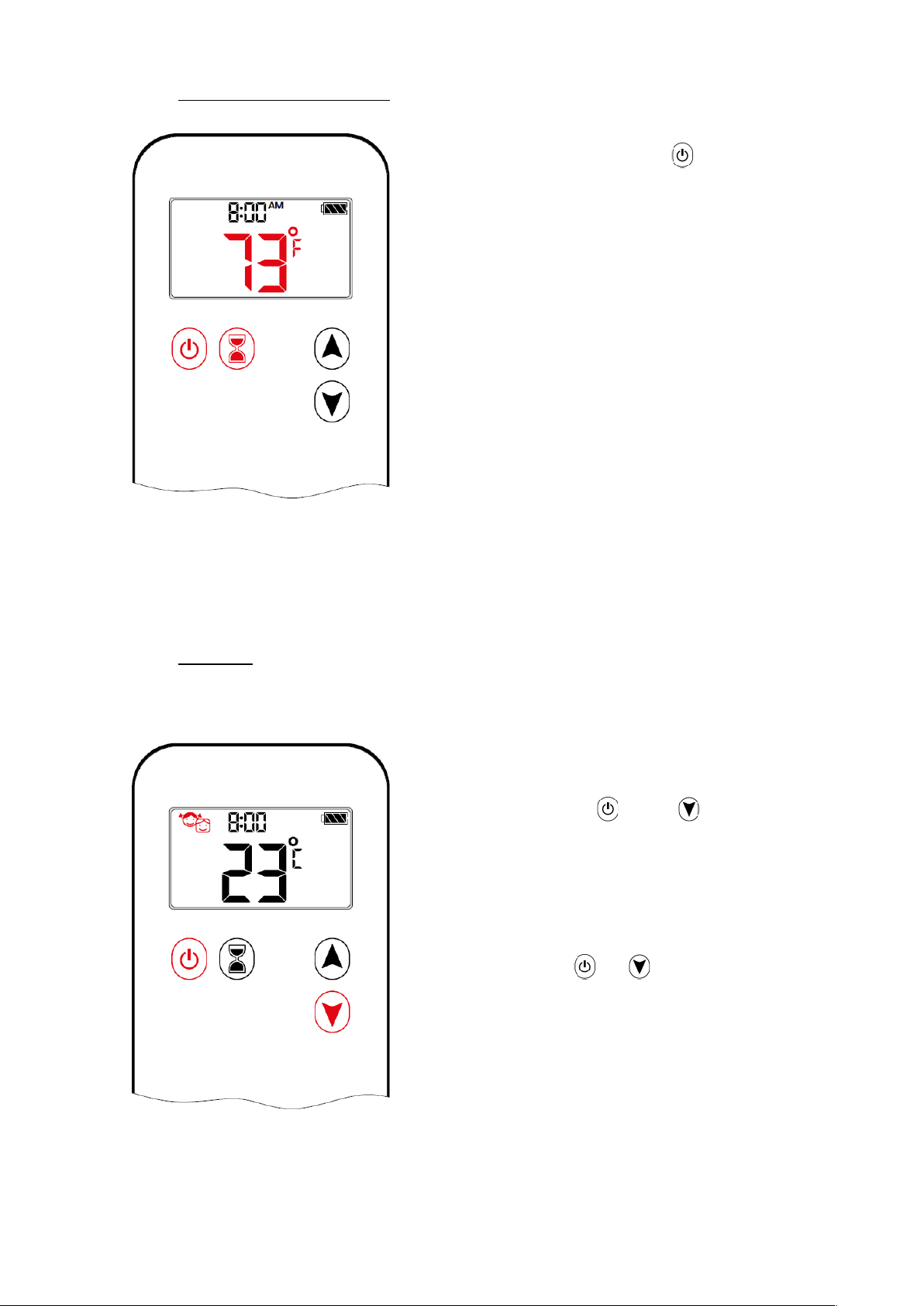
4.4.1. Setting Fahrenheit or Celsius
To change between °C and °F, press and
buttons simultaneously.
NOTE: Choosing °F results in a 12 hour clock.
Choosing °C results in a 24 hour clock.
4.4.2. Child Lock
Turn ON:
To activate press and buttons
simultaneously. is displayed and the
handset is rendered inoperable, except for the off
function.
Turn OFF:
To deactivate press and buttons
simultaneously. disappears.
Copyright Planika Sp. z o.o. www.planikafires.com IG0033#08 2020-03-20 21
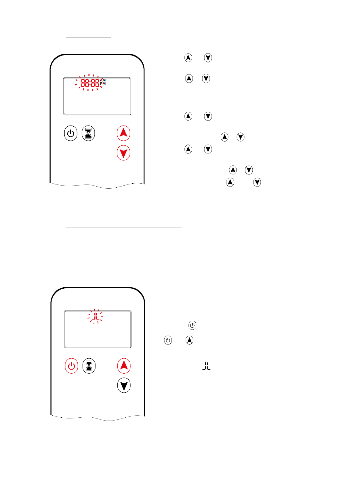
4.4.3. Setting the Time
1. Press and buttons simultaneously.
Day flashes.
2. Press or button to select a number to
correspond with the day of the week (1=Monday,
2 = Tuesday, 3 = Wednesday, 4 = Thursday,
5 = Friday, 6 = Saturday, 7 = Sunday).
3. Press and buttons simultaneously.
Hour flashes.
4. To select hour press or button.
5. Press and buttons simultaneously.
Minutes flash.
6. To select minutes press or button.
7. To confirm press and buttons
simultaneously or wait.
4.4.4. Switch on the Appliance / Igniting the Fire
Before operating make sure MANUAL knob on the GV60 valve is in the ON, full counter clockwise position.
WARNING! When the pilot light is ignited, the motor turns automatically to maximum flame height. If the pilot flame
goes out for any reason, wait for 5 minutes before attempting to re-light it. If the pilot does not stay lit after several
tries, turn the main valve knob to OFF.
1. Open the valve of the gas cylinder (or gas
supply valve in the gas pipe).
2. Press button (One Button Ignition) or
and button simultaneously (Two Button
Ignition) until two short beeps and a blinking
series of lines confirms the start sequence
has begun; release button(s).
3. Main gas flows once pilot ignition is confirmed.
4. Handset automatically goes into Manual Mode
after main burner ignition.
Copyright Planika Sp. z o.o. www.planikafires.com IG0033#08 2020-03-20 22
• This can take few seconds to ignite to pilot flame especially when you have replaced and installed a new LPG gas
cylinder.
• If the pilot light does not ignite after 3 ignition attempts close the gas tap and warn the fitter.
• Once the pilot light is burning, the main burner must ignite within 10 seconds automatically. If this does not
happen, immediately close the gas tap and warn the fitter.
• If the main burner ignites with a pop immediately close the gas tap and warn the fitter.
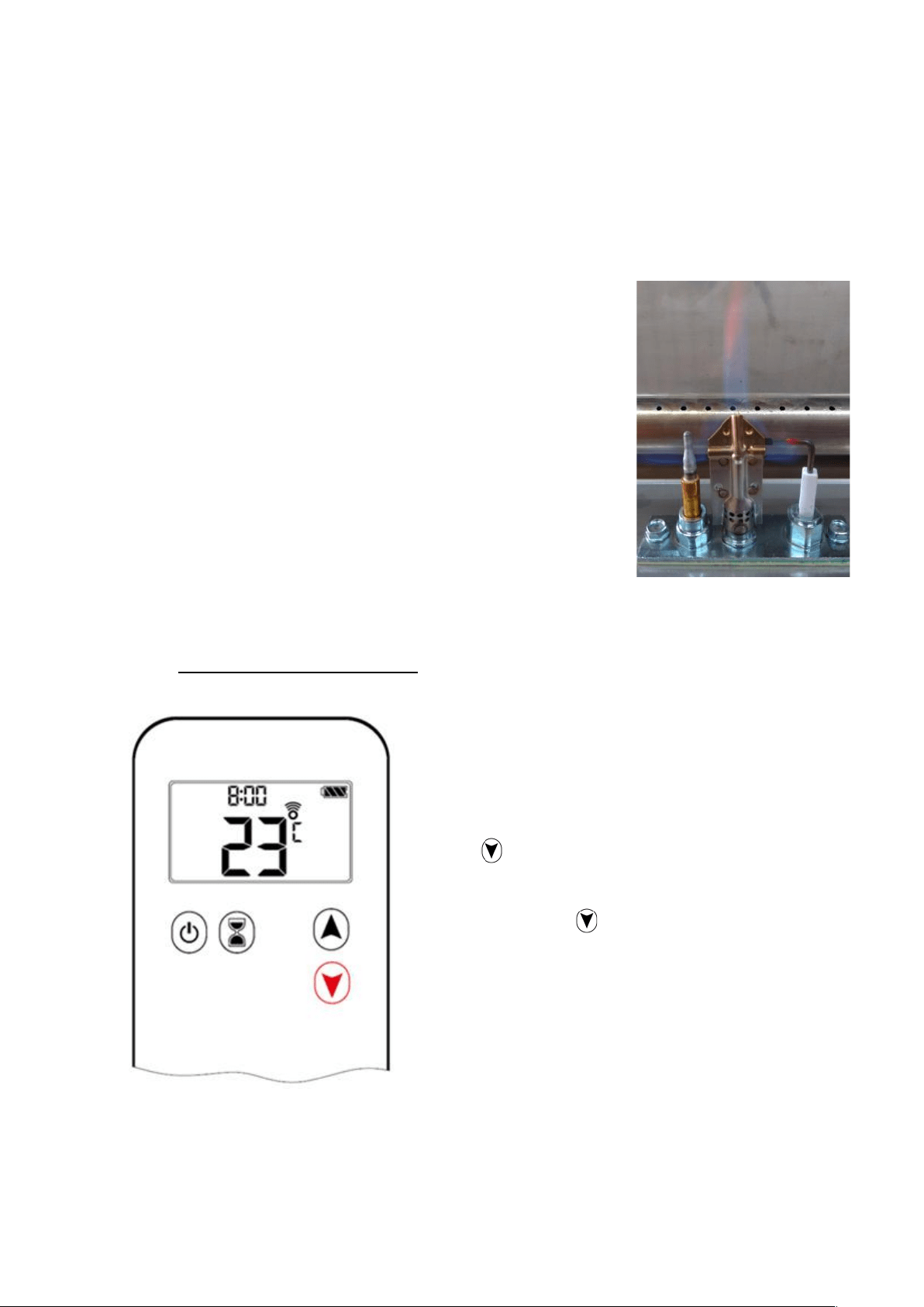
WARNING!!!
• Under conditions of increased humidity (rain, breeze, fog, dew, etc.),
there may be some temporary problems with switching on the fireplace.
This is a normal phenomenon associated with the dampening of the
ignition element.
• Before switching on the fireplace, wait until the ignition element has dried
completely.
• You can speed up this process by blowing the pilot flame with compressed
air to remove the accumulated moisture. The properly fired pilot flame
consist of 3 smaller parts.
4.4.5. Gradually decrease flame height
After ignition, the burner automatically sets the
flames to the maximum height.
Press button to lower the flames and to turn
off the burner.
Pressing briefly the button gradually lowers
the flames to the low position.
Copyright Planika Sp. z o.o. www.planikafires.com IG0033#08 2020-03-20 23
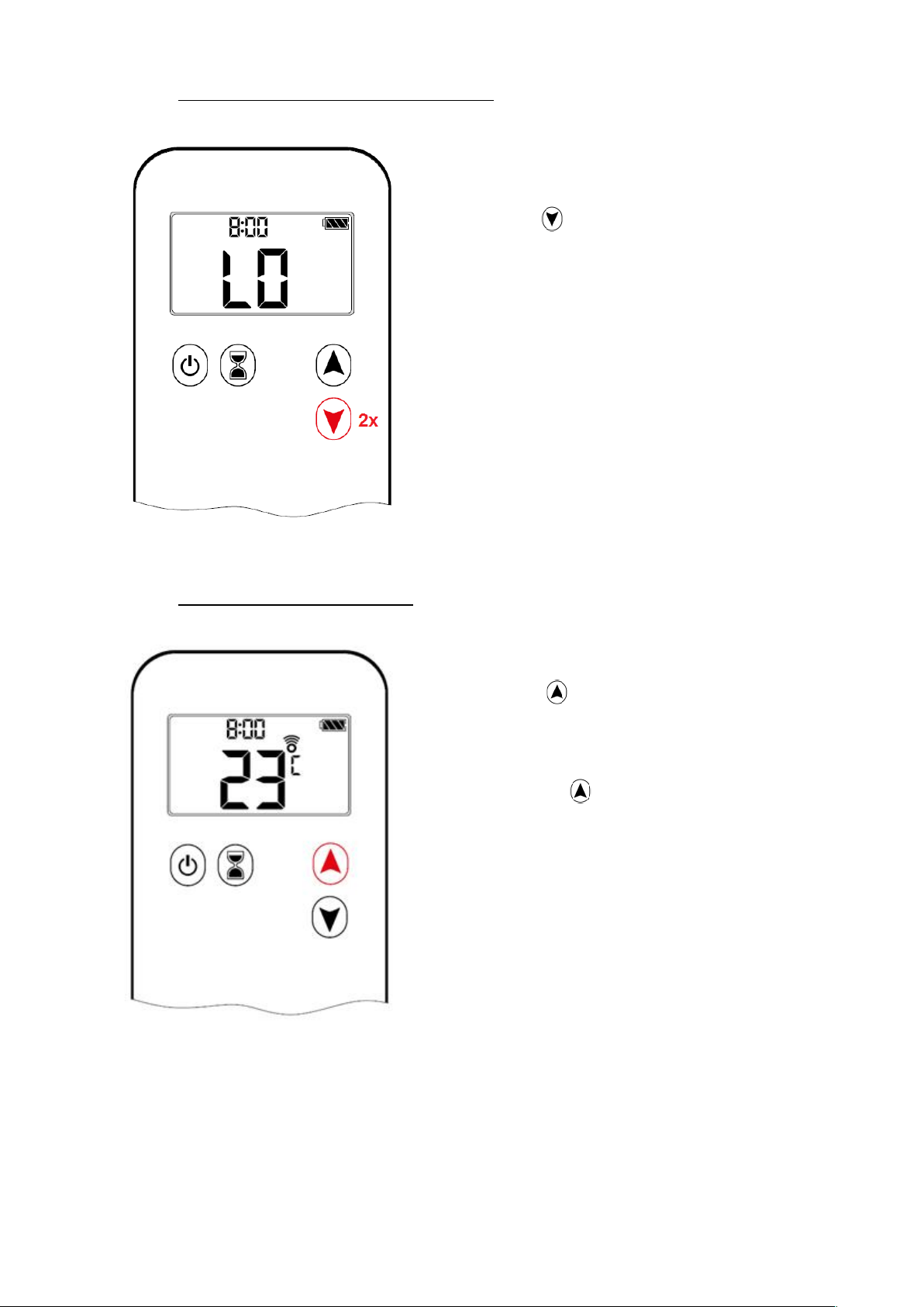
4.4.6. Flame height directly to minimum position
Pressing the button twice automatically
decreases the flames to the low position. This is
indicated by “LO” on the display.
NOTE: Flame goes to high fire first before going
to low fire. Backlight must be on for low fire
double-click operation!
4.4.7. Gradually increase flame height
Press and hold button to increase the flame
level and to turn on the burner from the stand-by
position.
Pressing briefly the button gradually increases
the flames to the high position.
NOTE: If you turn on the burner by pressing the
button, it must ignite within 10 seconds. If this
does not happen, immediately close the gas tap
and warn the fitter.
Copyright Planika Sp. z o.o. www.planikafires.com IG0033#08 2020-03-20 24
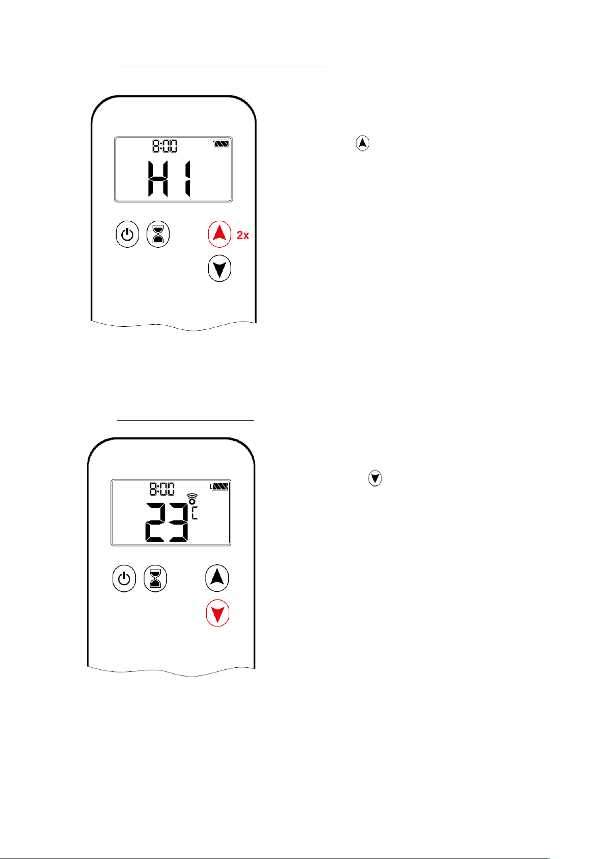
4.4.8. Flame height directly to maximum position
Pressing the button twice automatically
increases the flames to the high position. This is
indicated by “HI” on the display.
NOTE: Backlight must be on for high fire
double-click operation!
4.4.9. Stand-by mode (Pilot flame)
Press and hold button to set appliance to
pilot flame. Pilot flame remains burning (standby
position).
Copyright Planika Sp. z o.o. www.planikafires.com IG0033#08 2020-03-20 25
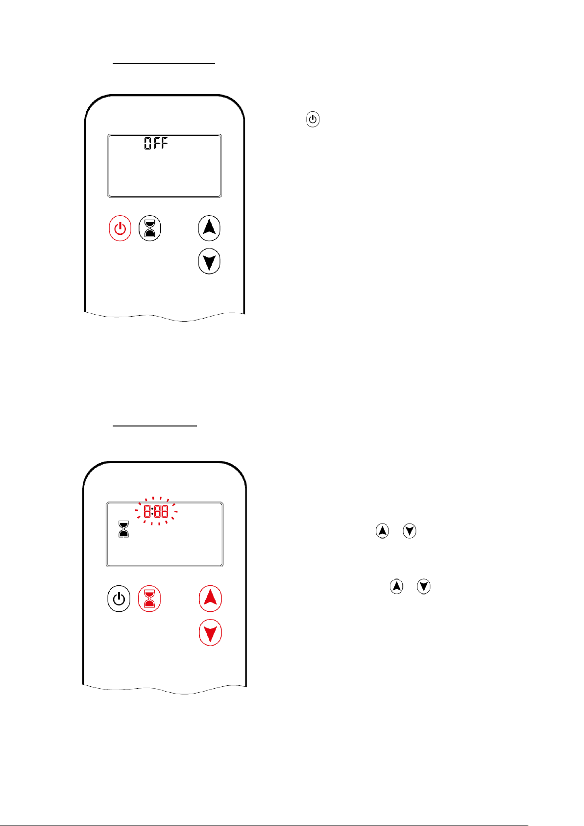
4.4.10. Turning off the device
Press button to turn off.
NOTE: A new ignition is possible after the OFF
icon stops flashing.
If the appliance is not to be used for some time,
please close the gas supply valve in the gas pipe
(or valve of the gas cylinder).
WARNING! If the pilot flame goes out for any
reason wait for 5 minutes before attempting to
re-light it.
4.4.11. Countdown Timer
ON / SETTING:
1. Press and hold button until displayed,
and hour flashes.
2. To select hour press or button.
3. To confirm press button. Minutes
flash.
4. To select minutes press or button.
5. To confirm press button or wait.
OFF:
Press button, and countdown time
disappear.
NOTE: At end of countdown time period, the fire shuts off. The maximum Countdown time is 9
hours and 50 minutes.

Copyright Planika Sp. z o.o. www.planikafires.com IG0033#08 2020-03-20 26
4.4.12. Automatic Turn Down To Pilot
3 Hour No Communication Function
The valve will turn to pilot flame if there is no communication between handset and receiver for a 3 hour period. The
fire will continue to function normally when communication is restored.
Receiver Overheating
• Powered by mains adapter: The valve turns to pilot flame if the receiver temperature is higher than 176 °F
(80 °C). If batteries are installed in the receiver in this configuration the temperature must not exceed 60 °C.
• Powered by batteries and/or connected to the V module: The valve turns to pilot position if the temperature
in the receiver is higher than 140 °F (60 °C).
NOTE: When the receiver temperature is below 140 °F (60 °C), the main burner can be turned ON manually.
4.4.13. Automatic Shut Off
Countdown Timer
At end of countdown time period, the fire shuts off. The Countdown Timer only works in Manual, Thermostatic, and
Eco Modes. Maximum countdown time is 9 hours and 50 minutes.
Low Battery Receiver
With low battery power in the receiver the system shuts off the fire completely. This will not happen if the power
supply is interrupted.
On-Demand Pilot
• This green feature eliminates gas energy consumption during extended appliance inactivity. When the appliance
is inactive for an extended period of time the system automatically extinguishes the pilot. This feature helps the
consumer realize cost benefits by automatically eliminating energy consumption during non-heating months and
limited use.
• The programmed length of inactivity to activate the system is specified by the appliance manufacturer and cannot
be altered in the field.
Copyright Planika Sp. z o.o. www.planikafires.com IG0033#08 2020-03-20 27
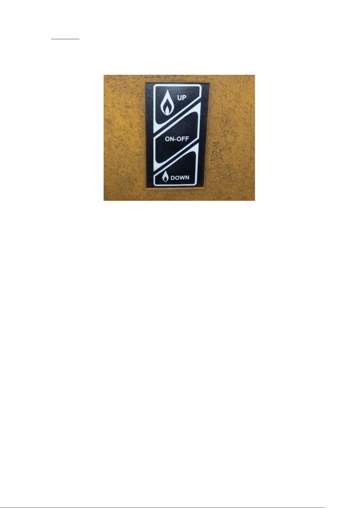
4.5. Touchpad
Depending on customers preferences GaLiO Corten Remote may be additionally operated Touch panel.
Photo 10: Touch panel
To Turn ON Appliance
• Press ON-OFF button (see Photo 10) until two short beeps confirm the start sequence has begun; release
button.
• Once pilot ignition is confirmed, there is main gas flow.
Standby Mode (Pilot Flame)
• Press and hold (small flame) button to set appliance at pilot flame.
To Turn OFF Appliance
• Press ON-OFF button.
Flame Height Adjustment
• Press and hold (large flame) button to increase flame height.
• Press and hold (small flame) button to decrease flame height or to set appliance at pilot flame.

Copyright Planika Sp. z o.o. www.planikafires.com IG0033#08 2020-03-20 28
5. TESTING
WARNING!!! NEVER TURN ON THE DEVICE IF THE CHARACTERISTIC SMELL OF GAS IS PERCEPTIBLE.
If you smell gas during the operation of the fireplace turn off the device immediately and cut off the gas supply from
the gas cylinder by shutting its valve.
5.1 Checking for gas leaks.
• Check if all connections are airtight.
• To do that apply all connections with soapy water (or water with another foamy substance) or with a
professional spray for leak detection.
• If air-bubbles are present that means the connection has a leak.
• Remove the leaks in the identified spaces.
• Check for leaks once again.
• After the inspection dry the inspected connections.
• The device may only be used again after all leaks are removed.
• If the problem happens again please contact the dealer.
5.2 Checking the flame appearance.
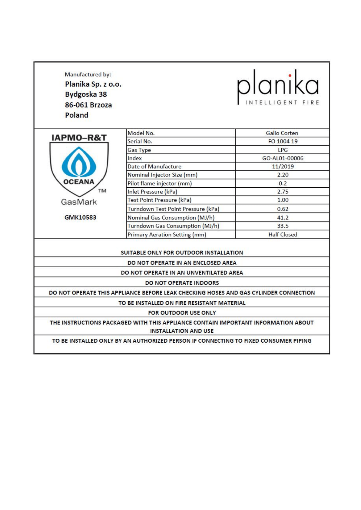
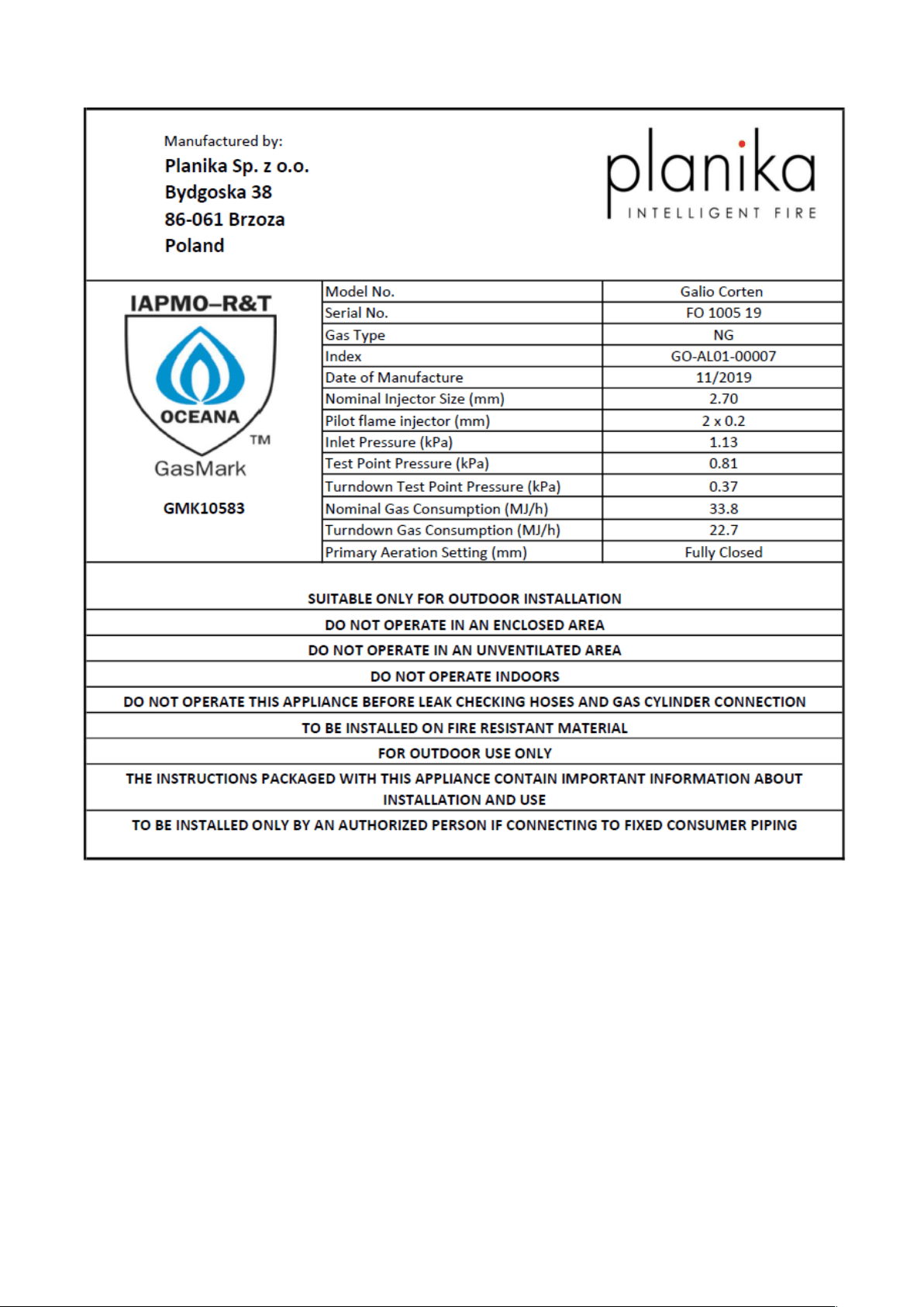
• Burn the GaLiO Corten on max flame height and check the appearance of the flame. Ensure test point pressure
is as per the data plate on the appliance and at the end of this manual.
• The flame should be linear and evenly placed on the whole length of the main burner.
• If visible gaps are present or there are substantial differences in flame height turn off the fireplace and after
the device is cooled adjust the placement of decorative stones in such a way for them to be evenly placed on
the whole surface of the main burner.
• WARNING!!! Stones must not cover the area between the burner and pilot cover, which houses the ignition
and the pilot flame.
• Turn on the fireplace and check the appearance of the flame once again.

Copyright Planika Sp. z o.o. www.planikafires.com IG0033#08 2020-03-20 29
6. MAINTENANCE AND UPKEEP
We recommend cleaning the pilot flame and the main burner unit before the device is started again and
after long intervals of inactivity.
6.1. Testing and cleaning
Please check and clean as necessary:
• The main burner - if necessary, remove broken parts of stones and dust.
• Pilot burner and thermo-couple (if necessary, remove the existing sediment). In the event of visible damage
contact your dealer.
• Igniter - gap between igniter and pilot flame should not be bigger than 5 mm.
• Glass guards – check for dirt smudges or possible scratches or cracks. If cracks are present replace the glass
guard for a new one. To conduct this contact your dealer. Always replace the guard following any
maintenance/servicing.
• Gas hose and pressure regulator (in case their expiry date is invalid replace these ancillaries for new ones).
• If you encounter problems with the regulator, gas hose, burner or regulation valves do not try to fix these
parts. Contact your place of purchase, an authorised service or an importer in order to acquire genuine spare
parts. To ensure the device is working efficiently use only original spare parts.
• Ensure controls, burners and circulating air passageways of the appliance are kept clean for safe operation.
6.2. Glass guard cleaning
Most of the existing types of smudges may be wiped with a dry cloth. In case of more substantial smudge you may use
liquids normally applied to ceramic tiles or windows. Always dry the glass screen to avoid damp patches which could
irreversibly embed into the glass.
WARNING!!! Avoid leaving fingerprints on the glass. They will be embedded into the glass and you will not be able to
clean them.

Copyright Planika Sp. z o.o. www.planikafires.com IG0033#08 2020-03-20 30
7. TROUBLESHOOTING
Warning! Installation, upkeep and service need to be conducted by a qualified professional with
appropriate qualification, an appropriate company or the gas supplier.
PROBLEM
POSSIBLE CAUSE
CORRECTIVE ACTION
SMELL OF GAS
CLOSE THE VALVE ON THE GAS CYLINDER IMMEDIATELY. DO NOT USE
THE DEVICE UNTIL LEAKS HAVE BEEN REMOVED.
Leak detected at cylinder,
regulator or other
connection.
1. A loose regulator linkage.
2. Leak in the gas linkage, in the
regulator or on the gas knobs.
1. Tighten and test it.
2. Report this issue to service.
Burner does not ignite
1. The bottle is empty.
2. Igniter linkage is not connected.
3. No ignition spark.
4. The igniter electrode is placed
incorrectly opposite the igniter.
5. Gas nozzles are blocked.
6. Gas linkage is twisted.
7. Pressure regulator link is loose.
1. Replace Gas Cylinder.
2. Connect the igniter linkage.
3. Replace igniter.
4. Realign electrode and clear any
surrounding debris from area.
5. Unmount burner, clean the nozzle.
6. Straighten the linkage. Keep the
linkage away from the housing.
7. Tighten the link. Check for leaks.
Igniter Not Working
1. Ignitor wire not connected.
2. Electrode misaligned on pilot
burner
3. Igniter malfunction
1. Ensure pilot electrode wire is
connected.
2. Realign electrode and clear any
surrounding debris from area.
3. Replace Igniter
Low efficiency, „cracking”
sounds
1. The bottle is empty.
2. The nozzles of the burner are
blocked.
1. Replace Gas Cylinder.
2. Unmount the burner, clean the
nozzle.
Thumping sounds made
by the regulator.
The cylinder valve has opened
rapidly.
Unfasten the bottle valve slowly.
A vivid/ bright orange and
smoky flame of the
burner.
Holes blocked in the apparatus
producing the gas and air mixture.
Unmount the burner and clean/
unblock the apparatus’ holes.

Copyright Planika Sp. z o.o. www.planikafires.com IG0033#08 2020-03-20 31
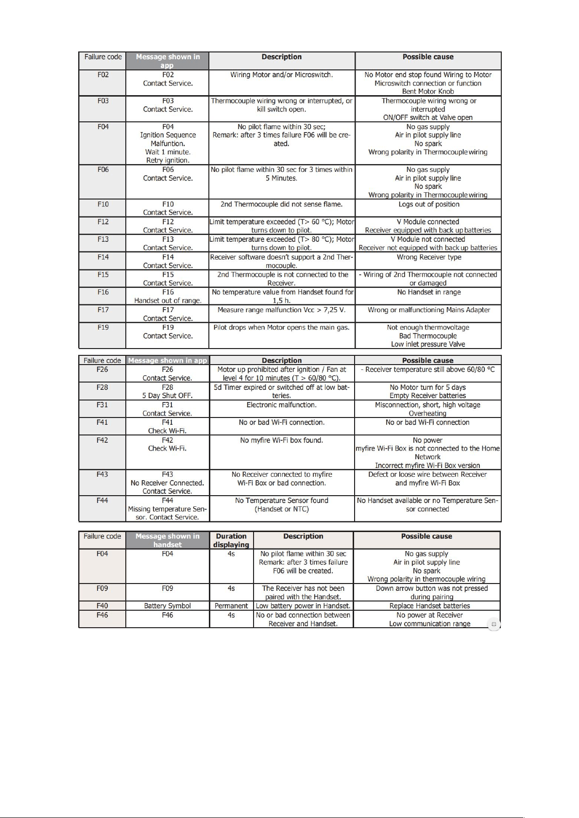
There are many factors that may affect the malfunction of the gas insert. To exclude a possible fault in the unit or
the automatic gas control system, make sure that the fireplace is connected according to these instructions.
Below table summarizes possible failures that may occur, possible causes and ways to solve them.
Copyright Planika Sp. z o.o. www.planikafires.com IG0033#08 2020-03-20 32
8. PRESSURE ADJUSTMENT
Do not attempt to remove screws from the top of gas valve. Do not change any adjustments marked with
tamper indicating paint. Motor knob is not to be removed.
Copyright Planika Sp. z o.o. www.planikafires.com IG0033#08 2020-03-20 33
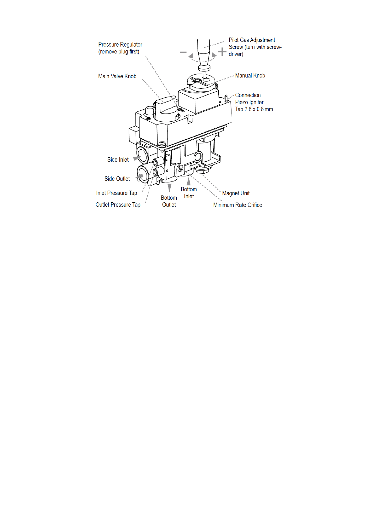
• Pilot Flame Adjustment
The pilot flow adjustment is preset to maximum at the factory. The pilot flame should envelope ⅜ʺ
to ½ʺ of the thermocouple
o The adjustment screw can be reached through a hole in the MANUAL knob (see figure 21).
o Turn the MANUAL knob to the ON position.
o It is now possible to pierce through a film on the cover with a screwdriver to reach the
adjustment screw beneath.
o Turn the adjustment screw clockwise to decrease or counterclockwise to increase pilot flame.
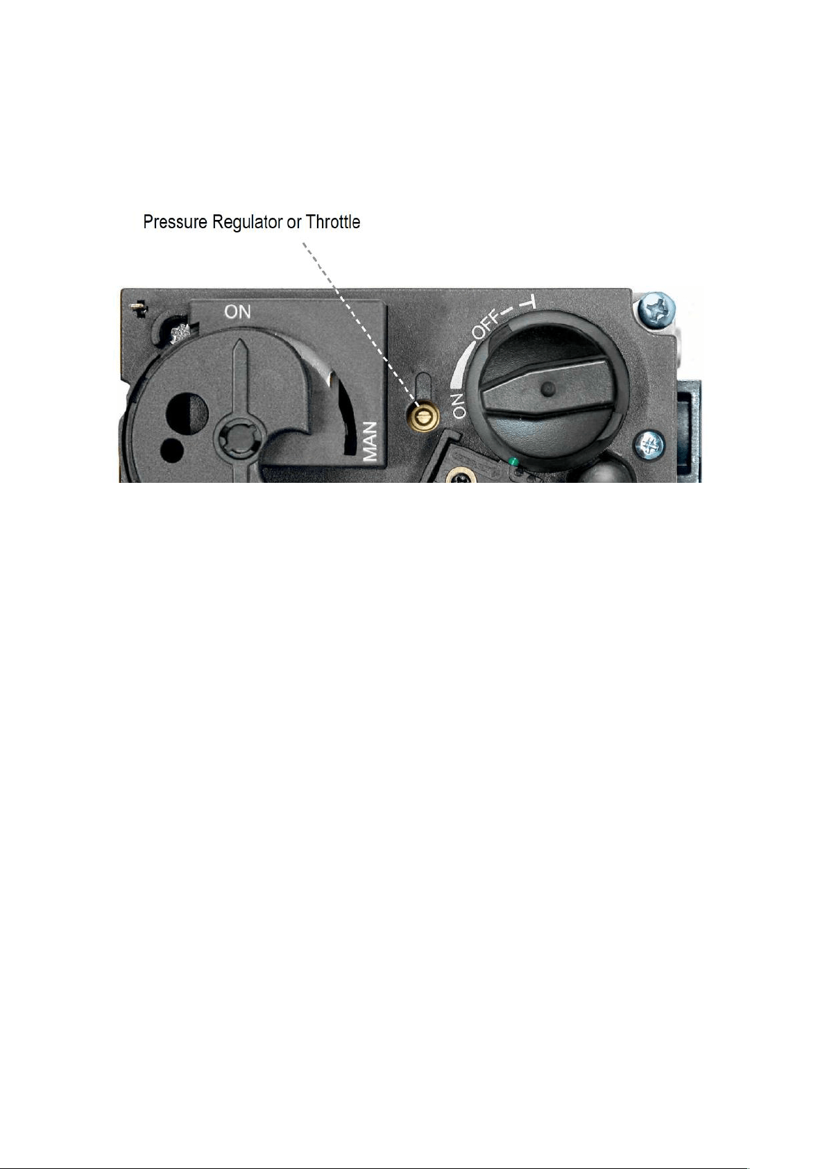
• Outlet Pressure Adjustment (High Fire)
o Connect a pressure manometer to the valve outlet pressure tap. Pressure tap is opened by
turning the screw counterclockwise. Pressure regulator or throttle are located under the cover
and can be reached by removing the plug (see figures 21 and 23).
Copyright Planika Sp. z o.o. www.planikafires.com IG0033#08 2020-03-20 34
o Turn MANUAL knob and main valve knob to the ON position.
o Turn pressure regulator adjustment screw to set required burner pressure (high fire). Pressure is
increased by turning clockwise (pressure regulator models), or decreased by turning
counterclockwise: LPG 1kPa, NG 0.81kPa
o After adjustment, replace the plug.
o If no other adjustments are required, close pressure tap(s) by turning the screw(s) full clockwise.
Check all connections/pressure tap(s) for leaks.
o If the desired outlet pressure or flow cannot be achieved by adjusting the gas valve, check the
gas valve inlet pressure using a manometer at the valve inlet pressure tap. If the inlet pressure is
in the normal range, replace the gas valve; otherwise, take necessary steps to assure proper gas
pressure to the valve
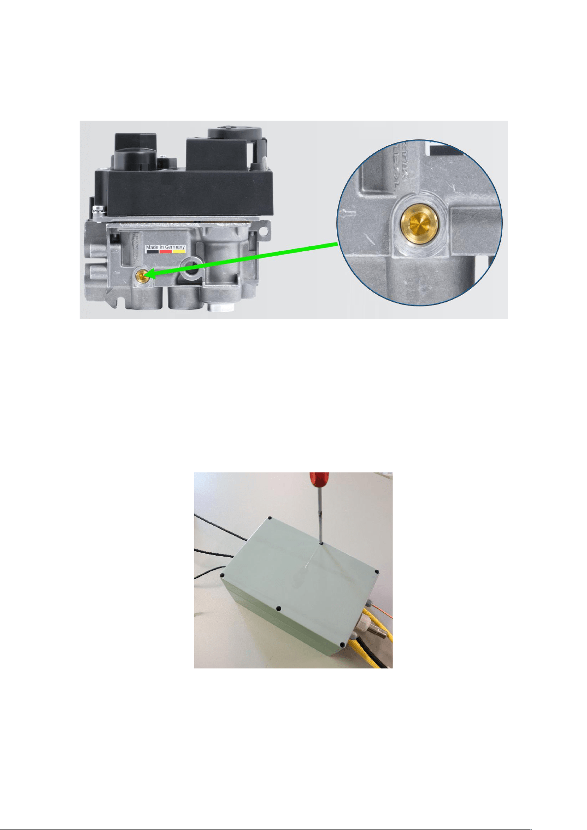
• Minimum rate Adjustment
o Connect a pressure manometer to the valve outlet pressure tap. Pressure tap is opened by
turning the screw counterclockwise. Minimum rate adjustment screw is located on the top of
the metal valve body.
Copyright Planika Sp. z o.o. www.planikafires.com IG0033#08 2020-03-20 35
o Turn minimum rate adjustment screw to set required burner pressure (minimum fire). Pressure
is increased by turning clockwise (pressure regulator models), or decreased by turning
counterclockwise: LPG 0.62kPa, NG 0.37kPa
Warning! You should never connect any device adapted to the combustion of liquefied gas to the gas network of
natural gas and vice versa.
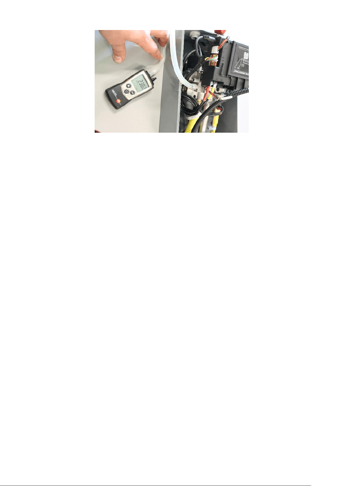
• Pressure reading
o Unscrew gas valve box cover using cross screwdriver.
o Take off the cover.

Copyright Planika Sp. z o.o. www.planikafires.com IG0033#08 2020-03-20 36
o Slightly take out the valve unit from valve box
o Unscrew the screw on the test tap by half a turn.
A) Inlet pressure tap
B) Outlet pressure tap
o Connect the silicon hose from measure device to the measure tap.
o Read the pressure value. Pressure test has to be made when fireplace is turned on with the highest flame
level.
B
A
Copyright Planika Sp. z o.o. www.planikafires.com IG0033#08 2020-03-20 37
o Screw tightly the screw on the test tap
o Turn on the device and check if screw is sealed using gas detector, foam or other method.
o Put on gas valve cover and screw it back.
Copyright Planika Sp. z o.o. www.planikafires.com IG0033#08 2020-03-20 38
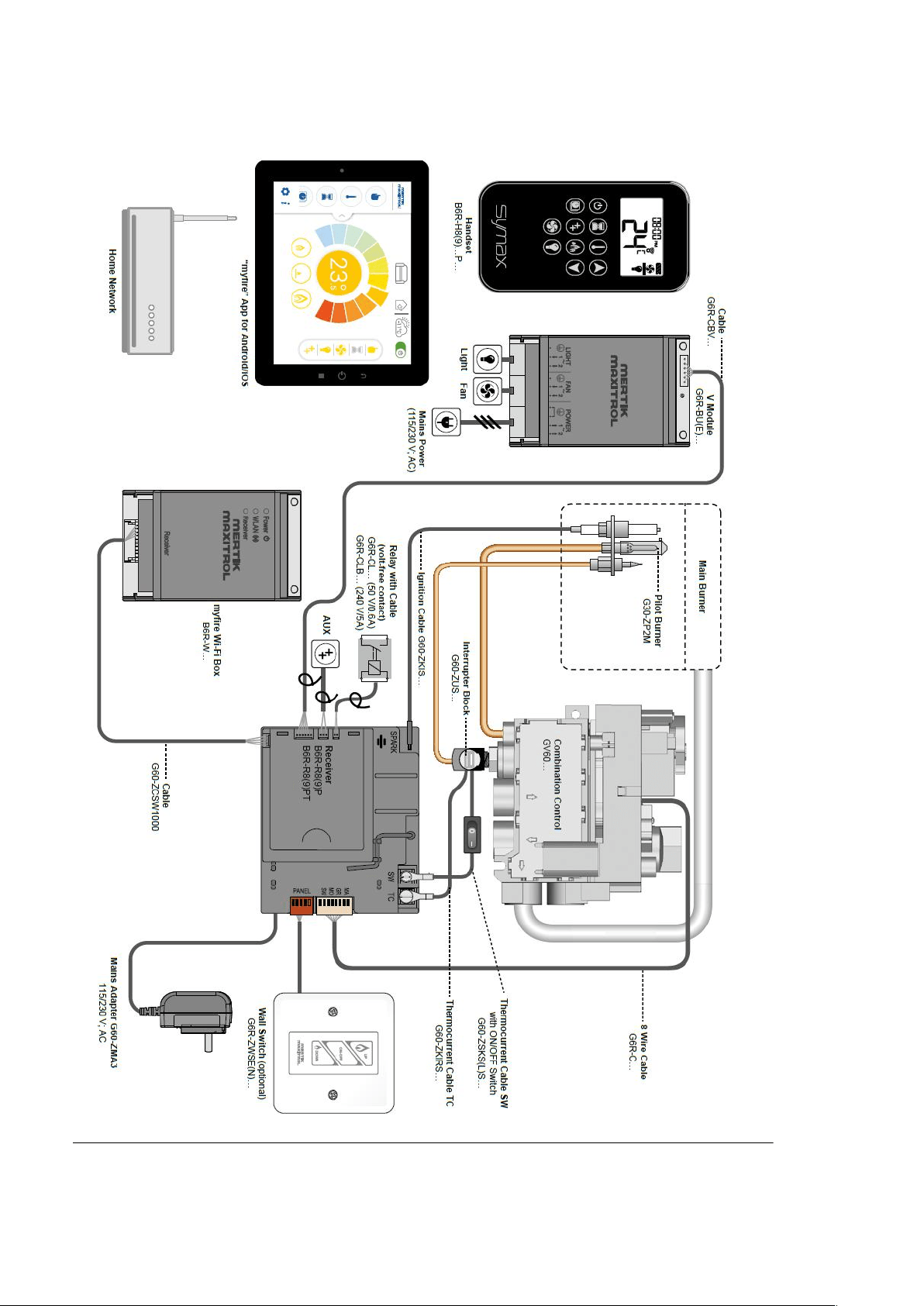
9. ELECTRICAL DIAGRAMS
Copyright Planika Sp. z o.o. www.planikafires.com IG0033#08 2020-03-20 39
10. TECHNICAL SPECIFICATION
Copyright Planika Sp. z o.o. www.planikafires.com IG0033#08 2020-03-20 40
11. MANUFACTURER’S CONTACT DETAILS
Company Name: Planika Sp. z o.o.
Address: Bydgoska 38
86-061 Brzoza
Poland
Telephone: + 48 52 364 11 60
Fax: + 48 52 364 11 70

Copyright Planika Sp. z o.o. www.planikafires.com IG0033#08 2020-03-20 41
12. DISTRIBUTOR’S CONTACT DETAILS
Company Name: Planika Australia
Address: 3/2 CYNAMIDE ST
LAVERTON NTH, VIC 3016,
AUSTRALIA
Telephone: + 61 415 350 564