Loading ...
Loading ...
INSTALLATION INSTRUCTIONS
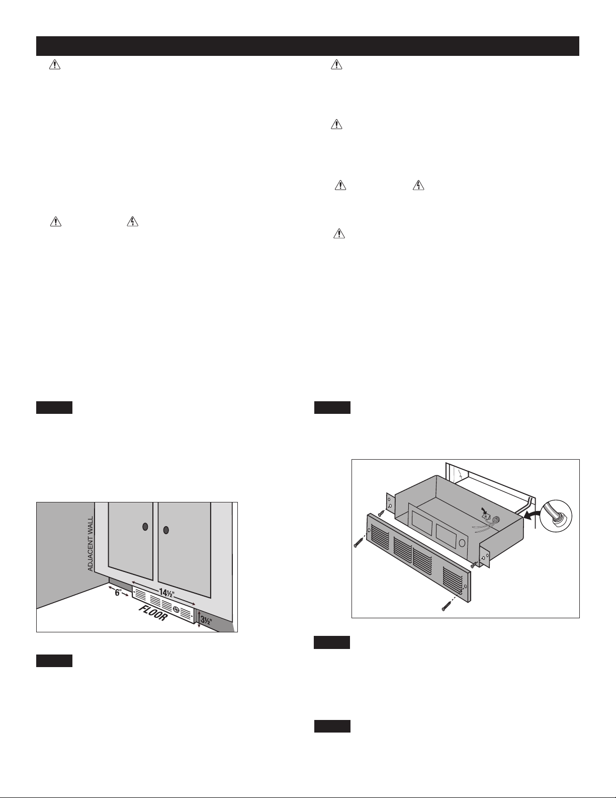
STRAIN RELIEF
CONNECTOR
GROUNDING
SCREW
1. WARNING
Verify that the electrical supply wires are the same
voltage as the heater.
2. If replacing an existing heater, check the label
of the old heater.
3. All electrical work and materials must comply
with the National Electric Code (NEC), the Occu-
pational Safety and Health Act (OSHA), and all
state and local codes.
4. If you need to install a new circuit or need addi-
tional wiring information, consult a qualied elec-
trician.
5. Use copper conductors only.
6. WARNING
Risk of Electrical Shock. DO NOT install the heat-
er directly above bathtub or sink. DO NOT install
in shower stall area (Manufacturer recommends a
minimum 2 foot clearance).
7. Heater must be installed in the wall can
included.
8. WARNING
Risk of Fire. DO NOT install the heater in a oor,
in the ceiling, below a towel bar, behind a door,
or anywhere the air discharge may be blocked in
any manner.
9. WARNING
Fire or Explosion May Occur. A heater has hot
and arcing or sparking parts inside. Do not use it
in areas where gasoline, paint, or ammable va-
pors or liquids are used or stored.
10. WARNING
Risk of Electrical Shock. Connect grounding lead
to grounding screw provided. Keep all foreign ob-
jects out of heater.
11. WARNING
Risk of Fire. This heater is hot when in use.
Caution—High Temperature. Risk of Fire. Keep
electrical cords, drapery, furnishings, and other
combustibles at least 3 feet from the front of the
heater and 6 inches above and on both sides.
__________________________
Part One
__________________________
PLACEMENT: For best results, install heater beneath a cabinet in the toe kick area. Install the Perfectoe (Model UC)
horizontally. Do not install the UC heater in the oor. Headers and bracing are not necessary. Heater must be installed per
the directions indicated on the lid.
WARNING! Vinyl oor manufacturers warn that some vinyl may discolor from temperatures in excess of 110° F. See your
vinyl oor manufacturer for temperature specications for your vinyl oor covering.
CONTROLS: A thermostat is required. A Cadet electronic thermostat is recommended for ultimate control and comfort.
Optional single or double pole eld mount thermostat kits are also available: Model numbers UCT1 and UCT2.
The UC Series heater REQUIRES A MINIMUM distance of 6
inches from adjacent surfaces (see Figure 1). However, Cadet
RECOMMENDS 12 inches from all adjacent surfaces for longer
and cleaner performance. Heaters must be spaced at least 3 feet
apart.
For installation in an existing wall/cabinet, cut a rough opening
14½ inches wide by 3½ inches high. Opening must be 8½ inches
deep.
STEP 1
Determine Area of Installation
Figure 1
Figure 2
STEP 2
Route Supply Wires
For wall thermostat applications, route supply wire from circuit
breaker to thermostat to rough opening. For models with an
optional eld mount thermostat kit, route supply wire from circuit
breaker to rough opening. Allow enough wire to extend 12 inches
beyond the opening. Place heater lid aside. Remove the knockout
and attach the supply wire with a strain relief connector, leaving 6
inches wire lead for later use (See Figure 2).
STEP 3
Connect Supply Wires
Connect the supply ground wire to the green grounding screw
provided (See Figure 2). Connect each supply wire to one heater
wire with wire connectors. Note: All wire connections must be
made inside the heater.
STEP 4
STEP 5
Mount the Heater
Turn the Electrical Power ON
Turn the electrical power back on at the electrical panel board
(circuit breaker or fuse box).
Reinstall heater lid and attach using four screws provided. Slide
heater into opening. Fasten heater to cabinet with screws (not
provided) going through the lower holes located on the anges.
Fasten grill to heater with screws provided going through the
upper holes located on the anges.
Page 3
Loading ...
Loading ...
Loading ...