1
W415-0297 / P / 02.03.12
SAFETY INFORMATION
- Do not store or use gasoline or other fl ammable
vapors and liquids in the vicinity of this or any
other appliance.
- WHAT TO DO IF YOU SMELL GAS:
• Do not try to light any appliance.
• Do not touch any electrical switch; do not use
any phone in your building.
• Immediately call your gas supplier from a
neighbour’s phone. Follow the gas supplier’s
instructions.
• If you cannot reach your gas supplier, call the
fi re department.
- Installation and service must be performed by a
qualifi ed installer, service agency or the supplier.
- This is an unvented gas-fi red heater that
uses air (oxygen) from the room in which it is
installed. Provisions for adequate combustion
and ventilation air must be provided. Refer to
section “ COMBUSTION AND VENTILATION AIR
PROVISIONS”.
INSTALLER: LEAVE THIS MANUAL WITH THE APPLIANCE.
CONSUMER: RETAIN THIS MANUAL FOR FUTURE REFERENCE.
NEVER LEAVE CHILDREN OR OTHER AT RISK INDIVIDUALS ALONE WITH THE APPLIANCE.
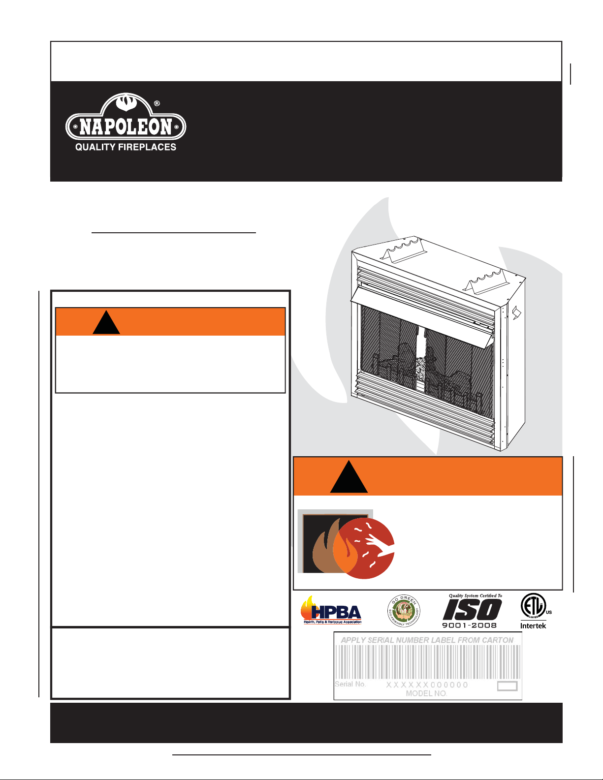
INSTALLATION AND
OPERATING INSTRUCTIONS
1.23B
Wolf Steel Ltd., 24 Napoleon Rd., Barrie, ON, L4M 0G8 Canada /
103 Miller Drive, Crittenden, Kentucky, USA, 41030
Phone (705)721-1212 • Fax (705)722-6031 • www.napoleonfi replaces.com • [email protected]
!
WARNING
If the information in these instructions are
not followed exactly, a fi re or explosion
may result causing property damage,
personal injury or loss of life.
CERTIFIED FOR THE UNITED STATES USING ANSI METHODS.
$10.00
This appliance may be installed in an aftermarket,
permanently located, manufactured (mobile) home,
where not prohibited by local codes.
This appliance is only for use with the type of gas
indicated on the rating plate. This appliance is not
convertible for use with other gases.
HOT GLASS WILL CAUSE
BURNS.
DO NOT TOUCH GLASS UNTIL
COOLED.
NEVER ALLOW CHILDREN TO
TOUCH GLASS.
!
WARNING
GVF36P
PROPANE
GVF36N
NATURAL GAS
CERTIFIED UNDER AMERICAN NATIONAL STANDARDS, ANSI Z21.11.2, VOLUME II FOR UNVENTED ROOM HEATERS.
UNVENTED MILLIVOLT
SYSTEM
2
W415-0297 / P / 02.03.12
NOTE: Changes, other than editorial, are denoted by a vertical line in the margin
TABLE OF CONTENTS
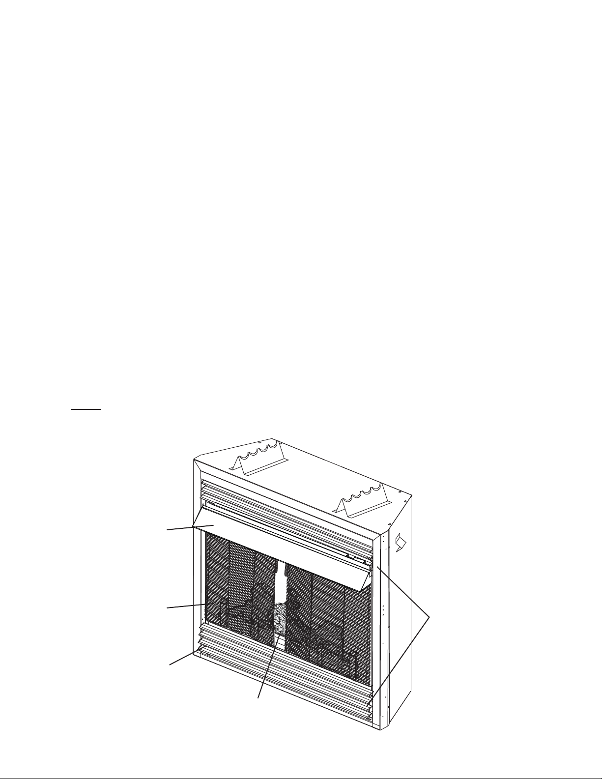
1.0 INSTALLATION OVERVIEW
Hood, see “HOOD”
section.
Louvres, see “L36
LOUVRE INSTALLATION”
section.
Curtain Mesh, see
“GRATE AND LOG
PLACEMENT” section.
Logs, see “GRATE AND LOG
PLACEMENT” section.
Rating Plate, see “RATING
PLATE INFORMATION”
section.
1.0 INSTALLATION OVERVIEW 2
2.0 INTRODUCTION 3
2.1 DIMENSIONS 4
2.2 GENERAL INSTRUCTIONS 4
2.3 GENERAL INFORMATION 5
2.4 RATING PLATE INFORMATION 6
3.0 INSTALLATION 6
3.1 COMBUSTION AND VENTILATION AIR PROVISIONS 6
3.2 DETERMINING CONFINED OR UNCONFINED SPACE 7
3.3 GAS INSTALLATION 8
3.4 OPTIONAL WALL SWITCH / THERMOSTAT 9
3.5 MOBILE HOME INSTALLATION 9
4.0 FRAMING 10
4.1 MINIMUM CLEARANCE TO COMBUSTIBLES 11
4.2 MINIMUM CLEARANCES TO COMBUSTIBLE ENCLOSURES 12
4.3 MINIMUM MANTEL CLEARANCES 12
4.4 NAILING TAB INSTALLATION 13
5.0 FINISHING 13
5.1 GRATE AND LOG PLACEMENT 13
5.2 CHARCOAL EMBERS 14
5.3 GLOWING EMBERS 14
5.4 HOOD 14
5.5 LOUVRE INSTALLATION 15
5.6 LOGO PLACEMENT 15
6.0 OPTIONAL BLOWER INSTALLATION 15
7.0 OPERATION 17
8.0 ADJUSTMENT 18
8.1 VENTURI ADJUSTMENT 18
8.2 FLAME CHARACTERISTICS 18
9.0 MAINTENANCE 19
9.1 OXYGEN DEPLETION SENSOR PILOT CLEANING 19
9.2 CARE OF PLATED PARTS 19
10.0 REPLACEMENTS 20
11.0 TROUBLE SHOOTING GUIDE 22
12.0 WARRANTY 25
13.0 SERVICE HISTORY 26
3
W415-0297 / P / 02.03.12
2.0 INTRODUCTION
3.4B
!
WARNING
• THIS APPLIANCE IS HOT WHEN OPERATED AND CAN CAUSE SEVERE BURNS IF CONTACTED.
• ANY CHANGES TO THIS APPLIANCE OR ITS CONTROLS CAN BE DANGEROUS AND IS PROHIBITED.
• Under no circumstances should this appliance be modifi ed.
• Do not operate appliance before reading and understanding operating instructions. Failure to operate
appliance according to operating instructions could cause fi re or injury.
• Risk of burns. The appliance should be turned off and cooled before servicing.
• Do not install damaged, incomplete or substitute components.
• Risk of cuts and abrasions. Wear protective gloves and safety glasses during installation. Sheet metal edges
may be sharp.
• Provide adequate ventilation and combustion air. Provide adequate accessibility clearance for servicing and
operating the appliance. Never obstruct the front opening of the appliance.
• If the appliance shuts off, do not re-light until you provide fresh air. If appliance keeps shutting off, have it
serviced. Keep burner and control compartment clean.
• Do not burn wood or other materials in this appliance.
• Children and adults should be alerted to the hazards of high surface temperature and should stay away to
avoid burns or clothing ignition.
• Young children should be carefully supervised when they are in the same room as the appliance. Toddlers,
young children and others may be susceptible to accidental contact burns. A physical barrier is recommended
if there are at risk individuals in the house. To restrict access to an appliance, install an adjustable safety gate
to keep toddlers, young children and other at risk individuals out of the room and away from hot surfaces.
• Due to high temperatures, the appliance should be located out of traffi c and away from furniture and
draperies.
• Ensure you have incorporated adequate safety measures to protect infants/toddlers from touching hot
surfaces.
• Clothing or other fl ammable material should not be placed on or near the appliance.
• Check with your local hearth specialty dealer for safety screens and hearth guards to protect children from
hot surfaces. These screens and guards must be fastened to the fl oor.
• Any safety screen or guard removed for servicing must be replaced prior to operating the appliance.
• It is imperative that the control compartments, burners and circulating blower and its passageway in the
appliance are kept clean. The appliance should be inspected before use and at least annually by a qualifi ed
service person. More frequent cleaning may be required due to excessive lint from carpeting, bedding
material, etc. The appliance area must be kept clear and free from combustible materials, gasoline and other
fl ammable vapours and liquids.
• Furniture or other objects must be kept a minimum of 4 feet away from the front of the appliance.
• Do not use this appliance if any part has been under water. Immediately call a qualifi ed service technician
to inspect the appliance and to replace any part of the control system and any gas control which has been
under water.
• Do not allow fans to blow directly into the appliance. Avoid any drafts that alter burner fl ame patterns.
• Do not use a blower insert, heat exchanger insert or other accessory not approved for use with this appliance.
• Carbon or soot should not occur in a vent free appliance as it can distribute into the living area of your home.
If you notice any signs of carbon or soot, immediately turn off your appliance and arrange to have it serviced
by a qualifi ed technician before operating it again.
• Keep the packaging material out of reach of children and dispose of the material in a safe manner. As with all
plastic bags, these are not toys and should be kept away from children and infants.
• As with any combustion appliance, we recommend having your appliance regularly inspected and serviced as
well as having a Carbon Monoxide Detector installed in the same area to defend you and your family against
Carbon Monoxide.
• If equipped, the screen must be in place (closed) when the appliance is in operation.
• Ensure clearances to combustibles are maintained when building a mantel or shelves above the appliance.
Elevated temperatures on the wall or in the air above the appliance can cause melting, discolouration or
damage to decorations, a T.V. or other electronic components.
4
W415-0297 / P / 02.03.12
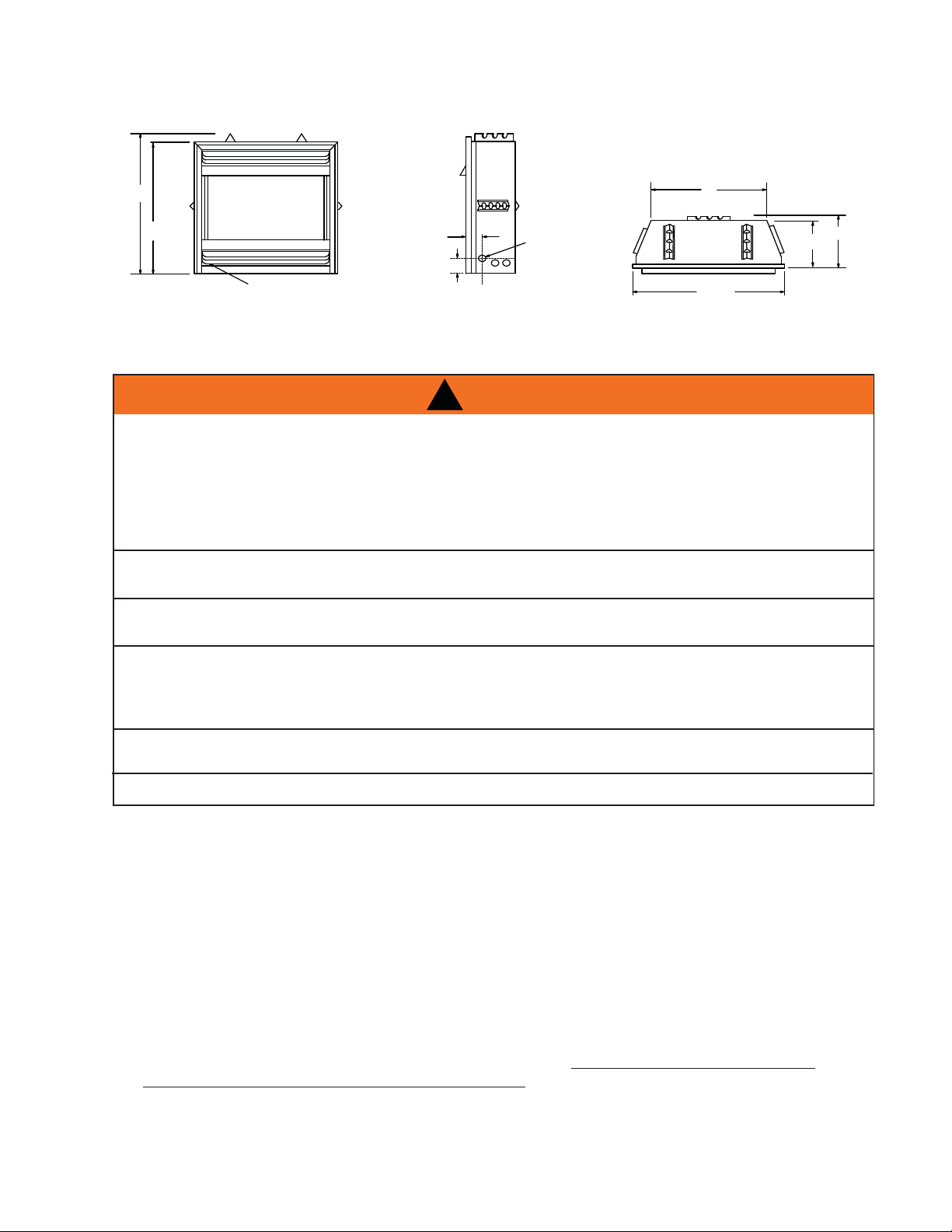
35
1
/2"
33"
3"
5
1
/2"
GAS
INLET
ELECTRICAL INLET
LEFT SIDE
27"
13
1
/4"
37
3
/8"
12
1
/4"
RATING PLATE
LOCATION
2.1 DIMENSIONS
This gas appliance should be installed and serviced by a qualifi ed installer to conform with local codes.
Installation practices vary from region to region and it is important to know the specifi cs that apply to your
area, for example: in Massachusetts State:
• The appliance off valve must be a “T” handle gas cock.
• The fl exible connector must not be longer than 36“.
• The appliance is not approved for installation in a bedroom or bathroom unless the appliance is a direct
vent sealed combustion product.
• A carbon monoxide detector is required in all rooms containing gas fi red appliances.
• WARNING: This product must be installed by a licensed plumber or gas fi tter when installed within the
commonwealth of Massachusetts.
• Un-vented room appliance shall be installed in accordance with 527 CMR 30.00 and 248 CMR 3.00
through 7.00.
• Sellers of un-vented propane or natural gas-fi red space / room appliances shall provide to each purchaser
a copy of 527 CMR 30.00 upon the sale of the appliance from http://www.napoleonfi replaces.com/
Webshare/installation_manuals/mass_requirements.pdf
!
WARNING
* CARBON MONOXIDE POISONING MAY LEAD TO DEATH
EARLY SIGNS OF CARBON MONOXIDE POISONING RESEMBLE THE FLU, WITH HEADACHE,
DIZZINESS AND/OR NAUSEA. IF YOU HAVE THESE SIGNS, THE HEATER MAY NOT BE WORKING
PROPERLY. GET FRESH AIR AT ONCE! HAVE HEATER SERVICED.
SOME PEOPLE---PREGNANT WOMEN, PERSONS WITH HEART OR LUNG DISEASE, ANEMIA,
THOSE UNDER THE INFLUENCE OF ALCOHOL, THOSE AT HIGH ALTITUDES--- ARE MORE
AFFECTED BY CARBON MONOXIDE THAN OTHERS.
THE APPLIANCE IS ONLY FOR USE WITH THE TYPE OF GAS INDICATED ON THE RATING PLATE.
THIS APPLIANCE IS NOT CONVERTIBLE FOR USE WITH OTHER GASES.
OBJECTS PLACED IN FRONT OF THE HEATER SHOULD BE KEPT A MINIMUM OF 48” AWAY FROM
THE FRONT FACE OF THE APPLIANCE.
USE ONLY WOLF STEEL APPROVED OPTIONAL ACCESSORIES AND REPLACEMENT PARTS WITH
THIS APPLIANCE. USING NON-LISTED ACCESSORIES AND REPLACEMENT PARTS (BLOWERS,
LOUVRES, TRIMS, GAS COMPONENTS, VENT COMPONENTS, ETC.) COULD RESULT IN A SAFETY
HAZARD AND WILL VOID THE LIMITED LIFETIME WARRANTY.
NOT DESIGNED FOR USE WITH A GLASS DOOR. SCREEN MUST BE CLOSED WHEN APPLIANCE IS
IN OPERATION.
THIS APPLIANCE MUST NOT BE INSTALLED IN A BEDROOM OR BATHROOM.
2.2 GENERAL INSTRUCTIONS
5
W415-0297 / P / 02.03.12
4.2C
In absence of local codes, install the appliance to the current National Fuel Gas Code, ANSI Z223.1
Installation Code which can be obtained from:
American National Standards Institute Inc. or National Fire Protection Association Inc.
1430 Broadway Batterymarch Park
New York, NY 10018 Quincy, MA 02269
The appliance and its individual shutoff valve must be disconnected from the gas supply piping system during
any pressure testing of that system at test pressures in excess of 1/2 psig (3.5 kPa). The appliance must be
isolated from the gas supply piping system by closing its individual manual shutoff valve during any pressure
testing of the gas supply piping system at test pressures equal to or less than 1/2 psig (3.5 kPa). When
installed with a blower the junction box must be electrically connected and grounded in accordance with local
codes. In the absence of local codes, use the current ANSI / NFPA 70 National Electric Code. In the case
where the blower is equipped with a power cord it must be connected into a properly grounded receptacle.
The grounding prong must not be removed from the cord plug.
As long as the required clearance to combustibles is maintained,
the most desirable and benefi cial location for the appliance is in the
center of a building, thereby allowing the most effi cient use of the
heat created. The location of windows, doors and the traffi c fl ow in
the room where the appliance is to be located should be considered.
If the appliance is installed directly on carpeting, vinyl tile or other
combustible material other than wood fl ooring, the appliance shall be installed on a metal or wood panel
extending the full width and depth. NOTE: This does not apply to stoves.
* Air shortage caused by an inadequate air supply, improper log positions, the addition of foreign or
unapproved materials or the failure to properly maintain the appliance, may result in incomplete combustion of
the fuel. Incomplete combustion results in soot being deposited inside the fi rebox as well as surfaces outside
the appliance. If any soot deposits are observed, shut off the appliance immediately and arrange for it to be
serviced by a qualifi ed technician.
We suggest that our gas
hearth products be installed
and serviced by professionals
who are certied in the U.S.
by the National Fireplace
Institute
®
(NFI) as NFI Gas
Specialists
www.ncertied.org
GVF36
NG LP
Altitude (FT) 0-4,500 0-4,500
Max. Input (BTU/HR) 30,000 30,000
Min. Inlet Gas Supply Pressure 4.5" Water Column 11" Water Column
Max. Inlet Gas Supply Pressure 7" Water Column 13" Water Column
Manifold Pressure (Under Flow Conditions) 3.5" Water Column 10" Water Column
2.3 GENERAL INFORMATION
6
W415-0297 / P / 02.03.12
When the appliance is installed at elevations above 2,000ft, and in the absence of specifi c recommendations
from the local authority having jurisdiction, the certifi ed high altitude input rating shall be reduced at the rate of
4% for each additional 1,000ft.
This appliance is only for use with the type of gas indicated on the rating plate. This appliance is not convertible
for use with other gases, unless a certifi ed kit is used.
No external electricity (110 volts or 24 volts) is required for the gas system operation.
Expansion / contraction noises during heating up and cooling down cycles are normal and to be expected.
This appliance is equipped with a pilot light safety system referred to as an oxygen depletion sensor and is
designed to turn off the appliance if not enough fresh air is available.
Use only accessories designed for and listed with your specifi c appliance.
Ceiling fans or oscillating type fl oor fans can cause fl ame impingement if directing air at the appliance. Imping-
ing fl ames will cause soot or carbon that may enter into living area. Try reversing ceiling fan or re-directing fl oor
fans to prevent sooting.
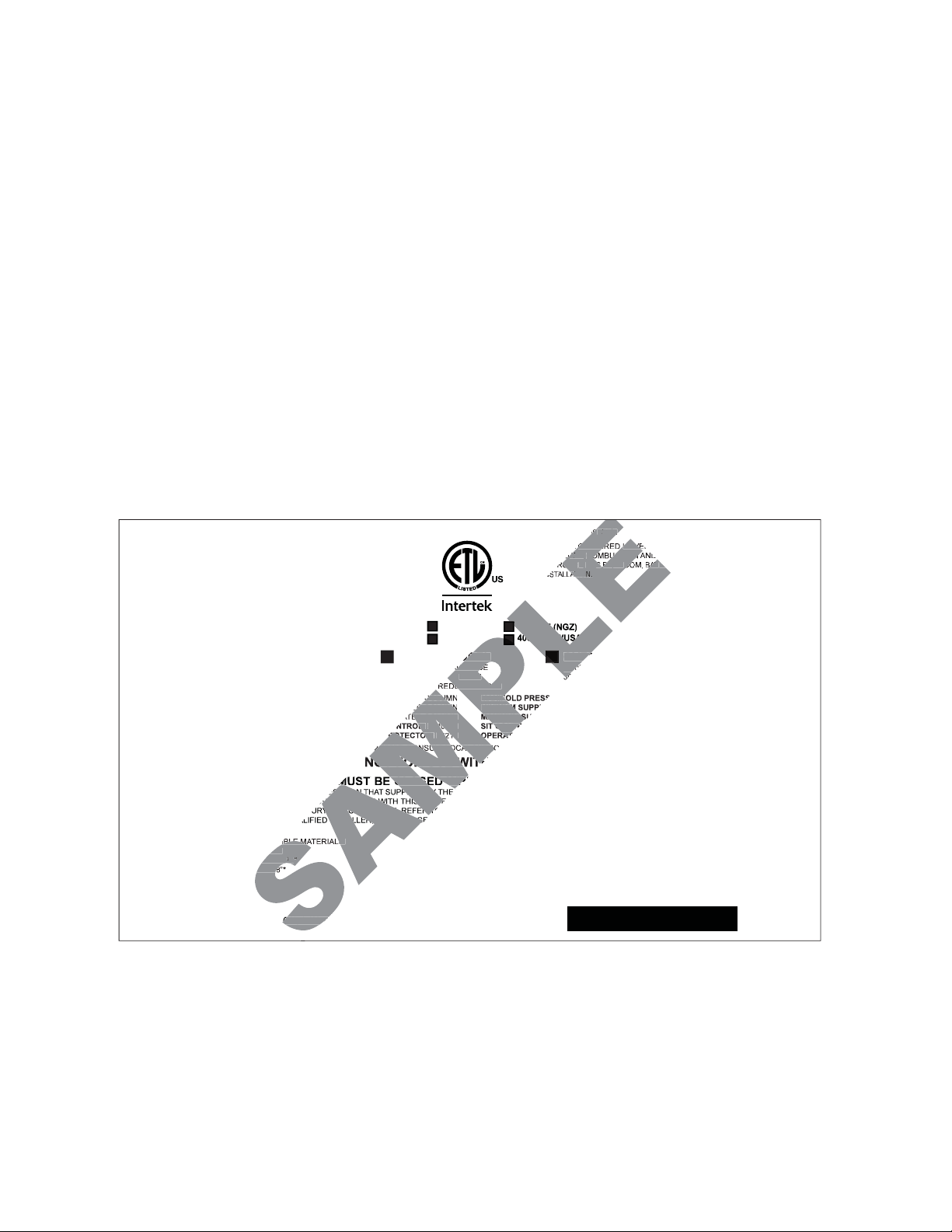
2.4 RATING PLATE INFORMATION
CERTIFIED UNDER: ANSI Z21.11.2a-2008 VOLUME II, UNVENTED ROOM HEATER
W385-0247 / G
SERIAL NUMBER: GVF36
WOLF STEEL LTD.
24 NAPOLEON ROAD, BARRIE, ON, L4M 0G8 CANADA
THIS APPLIANCE MAY BE INSTALLED IN AN AFTERMARKET,
PERMANENTLY LOCATED, MANUFACTURED (MOBILE) HOME, WHERE
NOT PROHIBITED BY LOCAL CODES. THIS APPLIANCE IS ONLY FOR USE
WITH THE TYPE OF GAS INDICATED ON THE RATING PLATE. THIS
APPLIANCE IS NOT CONVERTIBLE FOR USE WITH OTHER GASES.
THIS IS A GAS-FIRED UNVENTED ROOM HEATER THAT REQUIRES
ADEQUATE COMBUSTION AND VENTILATION AIR. THIS UNIT IS NOT
APPROVED FOR BEDROOM, BATHROOM AND BED-SITTING ROOM
INSTALLATION.
GVF36N / CVF36N MODEL GVF36P / CVF36P
**0-2000FT (0-610m) ALTITUDE 0-2000FT (0-610m)**
30,000 BTU/h INPUT 30,000 BTU/h
20,000 BTU/h REDUCED INPUT 22,000 BTU/h
MANIFOLD PRESSURE: 3.5" WATER COLUMN MANIFOLD PRESSURE: 10" WATER COLUMN
MINIMUM SUPPLY PRESSURE: 4.5" WATER COLUMN MINIMUM SUPPLY PRESSURE: 11" WATER COLUMN
MAXIMUM SUPPLY PRESSURE: 7.0" WATER COLUMN MAXIMUM SUPPLY PRESSURE: 13" WATER COLUMN
SIT CONTROL: #820637 SIT CONTROL: #820636
OPERATING PILOT OXYPROTECTOR: #8214 OPERATING PILOT OXYPROTECTOR: #8404
** ABOVE 2,000FT, CONSULT LOCAL AUTHORITY HAVING JURISDICTION
NOT FOR USE WITH SOLID FUEL.
WARNING: FIREPLACE SCREENS MUST BE CLOSED WHILE IN OPERATION. DO NOT ADD ANY MATERIAL TO THE APPLIANCE, WHICH
WILL COME IN CONTACT WITH THE FLAMES, OTHER THAN THAT SUPPLIED BY THE MANUFACTURER WITH THE APPLIANCE. DONOT USE BLOWER INSERT, HEAT EXCHANGER
INSERT OR OTHER ACCESSORIES NOT APPROVED FOR USE WITH THIS HEATER. IMPROPER INSTALLATION, ADJUSTMENT, ALTERATION, SERVICE OR MAINTAINANCE CAN
CAUSE PROPERTY DAMAGE, PERSONAL INJURY OR LOSS OF LIFE. REFER TO THE OWNER'S INFORMATION MANUAL PROVIDED WITH THIS APPLIANCE. INSTALLATION AND
SERVICE MUST BE PERFORMED BY A QUALIFIED INSTALLER, SERVICE AGENCY OR THE GAS SUPPLIER.
MINIMUM CLEARANCE TO COMBUSTIBLE MATERIALS:
TOP / SIDES / BACK / FLOOR 0”
RECESSED DEPTH 13
1
/
2
“
MANTEL 8”*
* MINIMUM CLEARANCE TO A COMBUSTIBLE MANTLE IS 12” WHEN USING A
CATALYTIC DOOR. MAXIMUM HORIZONTAL EXTENSION: 2". SEE INSTRUCTION
MANUAL FOR GREATER EXTENSIONS.
ELECTRICAL RATING: 115V 0.82AMP, 60HZ
OPTIONAL FAN KIT: GZ550-KT
9700539 (WSL) 4001657 (NGZ)
4001658 (NAC) 4001659 (WUSA)
For rating plate location, see “INSTALLATION OVERVIEW” section.
This illustration is for reference only. Refer to the rating plate on the appliance for accurate information.
SAMPLE
SAMPLE
HEHE
AA
TETE
AA
RR
ONON, L4, L4M 0M 0
GAS-GAS-FIRFIR
UNVEUNVE
UU
AA
TETE
AA
COMBCOMBUSTIUSTIONON
AA
RR
OVEOVE
DD
FOFO
RR
BEBE
DRDR
OOOO
BB
AA
TT
AA
HRHR
LL
AA
LL
TIOTIO
AA
NN
..
ODODEL EL
GVFGVF33
ALTIALTITUDETUDE
0-200-20
INPUINPUT T
3030
DUDUCED CED INPUINPUT T
PL
PL
CCOLUMOLUM
MANIMANIFOFO
ER ER COLUCOLUMNMN
MINIMINIMUM MUM
ER CER COLUMOLUMN N
MAXIMAXIMUM MUM SS
OL:OL:
#820#820637 637
T T CONTCONTRR
PPROTEROTECTORCTOR: :
#821#8214 4
OPEROPERATAT
2,2,000F000FT, CT, CONSUONSULT LLT LOCALOCAL AUT AUTHOHO
NONOT T FOFOR R USUSE E WIWITHTH
MUSMUST BT BE CE CLOSLOSED ED WHWH
ER ER THANTHAN THA THAT SUT SUPPLIPPLIED BED BY TY T
VEDVED FOR FOR USE USE WIT WITH THH THIS HIS HEATEEATE
Y OY OR LOR LOSS OSS OF LIF LIFE. FE. REFEREFER TOR TO
INSINSTALLTALLER, ER, SERVSERVICE ICE AGAG
IBLEIBLE MAT MATERIAERIALS:LS:
0”0”
13 13
11
//
22
““
88
40014001657 657 (N(N
001001659 659 (WUS(WUSA)A)
PL
PL
PL
PL
7
W415-0297 / P / 02.03.12
The GVF36 is rated at 30,000 BTUs per hour and therefore requires a minimum unconfi ned space of 1,500
cubic feet.
17.1A
This appliance shall not be installed in a con
fi
ned space or unusually tight construction unless provisions are
provided for adequate combustion and ventilation air.
The National Fuel Gas Code, ANSI Z223.1 / NFPA 54 defi nes a confi ned space as a space whose volume is
less than 50 cubic feet per 1,000 Btu per hour (4.8 m3 per kw) of the aggregate input rating of all appliances
installed in that space and an unconfi ned space as a space whose volume is not less than 50 cubic feet per
1,000 Btu per hour (4.8 m3 per kw) of the aggregate input rating of all appliances installed in that space.
Rooms communicating directly with the space in which the appliances are installed, through openings not
furnished with doors are considered a part of the unconfi ned space.
3.0 INSTALLATION
3.1 COMBUSTION AND VENTILATION AIR PROVISIONS
To determine the volume o
f
the room where the appliance is to be installed, multiply the width x the length x
the ceiling height of that room measured in feet. If any adjoining rooms are connected by grilles or openings
such as kitchen pass-throughs, etc., the volume of those rooms may be added to the total.
Multiply the room volume by 1000 and divide this amount by 50 to determine the maximum BTU/hr that the
space can support with adequate combustion and ventilation air.
A
dd the Btu/hr of all fuel burning appliances located within the space such as gas furnace, gas water
appliance, etc. Do not include direct vent gas appliances which draw their input and output air from and to the
outdoors.
Unusually tight construction is defi ned as construction where:
A) Walls and ceilings exposed to the outside atmosphere have a continuous water vapour retarder with a
rating of 1 perm (6 x 10-11 kg per pa-sec-m2) or less with openings gasketed or sealed, and
B) Weather stripping has been added on openable windows and doors, and
C) Caulking or sealants are applied to areas such as joints around window and door frames, between sole
plates and fl oors, between wall-ceiling joints, between wall panels, at penetrations for plumbing, electrical,
and gas lines, and at other openings.
A
n unvented room appliance is recommended for use as a secondary heat source rather than as a primary
source. Gas combustion produces water vapour which could occur at the rate of approximately one ounce of
water for every 1,000 BTU/hr of gas input. During the cold weather season, indoor humidity levels tend to be
low. Consequently, this water vapour can enhance the living space. However if a problem should occur:
A) Ensure suffi cient combustion and circulation air
B) Use a dehumidifi er
C) Do not use the unvented room appliance as a primary heat source
Without suffi cient fresh air for proper operation, poor fuel combustion can result. Carbon Monoxide is a result
of poor combustion.
If additional fresh air is required, use one of the methods described in the National Fuel Gas Code, ANSI
Z223.1 / NFPA54 or the applicable local code.
!
WARNING
IF THE AREA IN WHICH THE APPLIANCE MAY BE OPERATED IS SMALLER THAN THAT DEFINED AS
AN UNCONFINED SPACE OR IF THE BUILDING IS OF UNUSUALLY TIGHT CONSTRUCTION, PROVIDE
ADEQUATE COMBUSTION AND VENTILATION AIR BY ONE OF THE METHODS DESCRIBED IN THE
NATIONAL FUEL GAS CODE ANSI Z223.1/ NFPA 54 , AIR FOR COMBUSTION AND VENTILATION, OR THE
APPLICABLE LOCAL CODE.
IF THE AREA IN WHICH THE APPLIANCE MAY BE OPERATED DOES NOT MEET THE REQUIRED VOLUME
FOR INDOOR COMBUSTION AIR, COMBUSTION AND VENTILATION AIR SHALL BE PROVIDED BY ONE
OF THE METHODS DESCRIBED IN THE ANSI Z223.1 / NFPA 54, THE INTERNATIONAL FUEL GAS CODE,
OR APPLICABLE LOCAL CODES.
3.2 DETERMINING CONFINED OR UNCONFINED SPACE
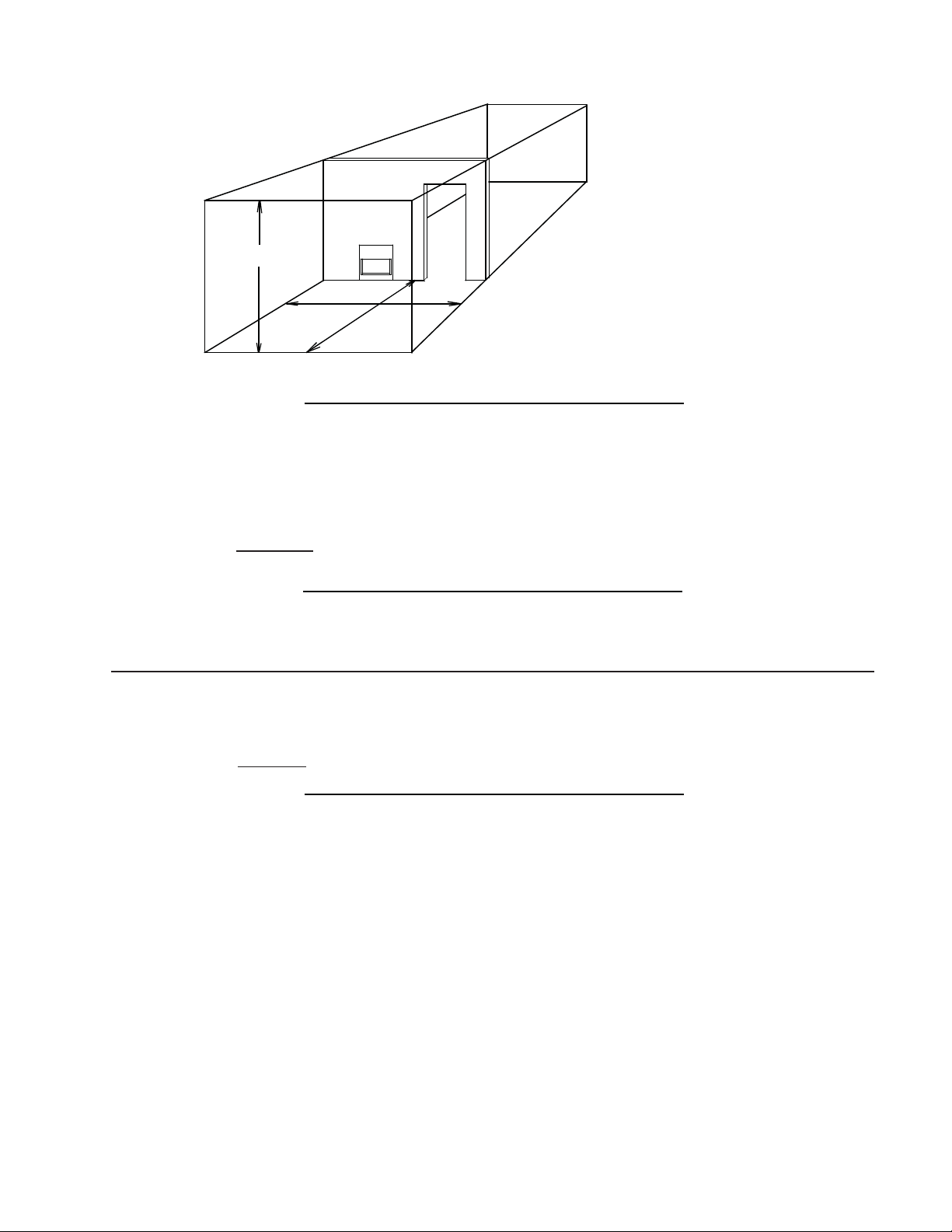
8
W415-0297 / P / 02.03.12
19.2
EXAMPLE 1:
In this example, because there is no door to the adjoining room, the volume of the adjoining room may be
added to the volume of the room with the heater to get a total unconfi ned space.
The total unconfi ned space: 800 + 1200 = 2000 cubic feet.
Maximum BTU/h: 2000x1000 = 40,000 BTU/h
50
If there are no more fuel burning appliances within this space then the 30,000 BTU/h input of the appliance is
suitable to be installed. This also assumes that the construction of this space is not unusually tight.
19.3
EXAMPLE 2:
If in this example a solid door separates Room 1 from Room 2, the volume of Room 2 could not be used. In
this case the maximum BTU/h would be:
Maximum BTU/h: 800x1000 = 16,000 BTU/h
50
This would be considered a confi ned space since it can not support the 30,000 BTU/h input of the appliance
and it would be necessary to provide adequate combustion and ventilation air to Room 1.
19.1B
Room Volume = Length x Width x Height
Max BTU/hr = Room Volume x 1000 / 50
LENGTH
HEIGHT
ROOM 2
ROOM 1
WIDTH
If for example:
The length of the rooms is 10 feet,
The width of Room 1 is 10 feet,
The width of Room 2 is 15 feet,
The height of the rooms is 8 feet.
The volume of Room 1: 10x10x8 = 800 cubic feet
The volume of Room 2: 10x15x8 = 1200 cubic feet
9
W415-0297 / P / 02.03.12
3.3 GAS INSTALLATION
30.1A
Installation and servicing to be done by a qualifi ed installer.
A. Move the appliance into position and secure.
B. If equipped with a fl ex connector the appliance is designed to accept a 1/2” gas supply. Without the
connector it is designed to accept a 3/8” gas supply. The appliance is equipped with a manual shut off
valve to turn off the gas supply to the appliance.
C. Connect the gas supply in accordance to local codes. In the absence of local codes, install to the
current CAN/CSA-B149.1 Installation Code in Canada or to the current National Fuel Gas Code, ANSI
Z223.1 / NFPA 54 in the United States.
D. When fl exing any gas line, support the gas valve so that the lines are not bent or kinked.
E. The gas line fl ex-connector should be installed to provide suffi cient movement for shifting the burner
assembly on it’s side to aid with servicing components.
F. Check for gas leaks by brushing on a soap and water solution. Do not use open fl ame.
!
WARNING
RISK OF FIRE, EXPLOSION OR ASPHYXIATION. ENSURE THERE ARE NO IGNITION SOURCES SUCH AS
SPARKS OR OPEN FLAMES.
SUPPORT GAS CONTROL WHEN ATTACHING GAS SUPPLY PIPE TO PREVENT DAMAGING GAS LINE.
ALWAYS LIGHT THE PILOT WHETHER FOR THE FIRST TIME OR IF THE GAS SUPPLY HAS RUN OUT
WITH THE GLASS DOOR OPENED OR REMOVED. PURGING OF THE GAS SUPPLY LINE SHOULD BE
PERFORMED BY A QUALIFIED SERVICE TECHNICIAN. ASSURE THAT A CONTINUOUS GAS FLOW IS AT
THE BURNER BEFORE CLOSING THE DOOR. ENSURE ADEQUATE VENTILATION. FOR GAS AND
ELECTRICAL LOCATIONS, SEE “DIMENSION” SECTION.
ALL GAS CONNECTIONS MUST BE CONTAINED WITHIN THE APPLIANCE WHEN COMPLETE.
HIGH PRESSURE WILL DAMAGE VALVE. DISCONNECT GAS SUPPLY PIPING BEFORE TESTING GAS
LINE AT TEST PRESSURES ABOVE 1/2 PSIG.
VALVE SETTINGS HAVE BEEN FACTORY SET, DO NOT CHANGE.
3.4 OPTIONAL WALL SWITCH / THERMOSTAT
For ease of accessibility, an optional remote wall switch or millivolt thermostat may be installed in a convenient
location. Route a 2 strand, solid core millivolt wire from the valve to the wall switch or millivolt thermostat. The
recommended maximum lead length depends on wire size:
WIRE SIZE MAX. LENGTH
14 gauge 100 feet
16 gauge 60 feet
18 gauge 40 feet
Disconnect the existing wires from terminals 1 and 3 (from the
ON/OFF switch) and replace with the leads from the wall switch / millivolt thermostat.
50.1
3
1
2
!
WARNING
DO NOT CONNECT EITHER THE WALL SWITCH, THERMOSTAT OR GAS VALVE DIRECTLY TO 110
VOLT ELECTRICITY.

10
W415-0297 / P / 02.03.12
!
WARNING
RISK OF FIRE!
IN ORDER TO AVOID THE POSSIBILITY OF EXPOSED INSULATION OR VAPOUR BARRIER COMING
IN CONTACT WITH THE APPLIANCE BODY, IT IS RECOMMENDED THAT THE WALLS OF THE
APPLIANCE ENCLOSURE BE “FINISHED” (IE: DRYWALL / SHEETROCK), AS YOU WOULD FINISH
ANY OTHER OUTSIDE WALL OF A HOME. THIS WILL ENSURE THAT CLEARANCE TO
COMBUSTIBLES IS MAINTAINED WITHIN THE CAVITY.
DO NOT NOTCH THE FRAMING AROUND THE APPLIANCE STAND-OFFS. FAILURE TO MAINTAIN
AIR SPACE CLEARANCE MAY CAUSE OVER HEATING AND FIRE. PREVENT CONTACT WITH
SAGGING OR LOOSE INSULATION OR FRAMING AND OTHER COMBUSTIBLE MATERIALS. BLOCK
OPENING INTO THE CHASE TO PREVENT ENTRY OF BLOWN-IN INSULATION. MAKE SURE
INSULATION AND OTHER MATERIALS ARE SECURED.
WHEN CONSTRUCTING THE ENCLOSURE ALLOW FOR FINISHING MATERIAL THICKNESS TO
MAINTAIN CLEARANCES. FRAMING OR FINISHING MATERIAL CLOSER THAN THE MINIMUMS
LISTED MUST BE CONSTRUCTED ENTIRELY OF NON-COMBUSTIBLE MATERIALS. MATERIALS
CONSISTING ENTIRELY OF STEEL, IRON, BRICK, TILE, CONCRETE, SLATE, GLASS OR PLASTERS,
OR ANY COMBINATION THEREOF ARE SUITABLE. MATERIALS THAT ARE REPORTED AS PASSING
ASTM E 136, STANDARD TEST METHOD FOR BEHAVIOUR OF MATERIALS IN A VERTICAL TUBE
FURNACE AT 750°C AND UL763 SHALL BE CONSIDERED NON-COMBUSTIBLE MATERIALS.
MINIMUM CLEARANCE TO COMBUSTIBLES MUST BE MAINTAINED OR A SERIOUS FIRE HAZARD
COULD RESULT.
THE APPLIANCE REQUIRES A MINIMUM ENCLOSURE HEIGHT. MEASURE FROM THE APPLIANCE
BASE.
IF STEEL STUD FRAMING KITS WITH CEMENT BOARD ARE PROVIDED, THEY MUST BE
INSTALLED.
71.1
29.2
S
uitable
f
or mobile home installation where the mobile home has been permanently placed on its site.
This appliance may be installed in an aftermarket permanently located, manufactured (mobile) home, where
not prohibited by local codes.
For mobile home installations, the appliance must be fastened in place. It is recommended that the appliance
be secured in all installations. See “REPLACEMENTS” section for the levelling / securing kit specifi c to your
appliance.
3.5 MOBILE HOME INSTALLATION
Combustible materials may be installed fl ush with the front of the appliance but must not cover any of the black
face-areas of the appliance. Non-combustible material (brick, stone or ceramic tile) may protrude in these
areas.
It is not necessary to install a hearth extension with this appliance system.
When roughing in the appliance, raise the appliance to accommodate for the thickness of the fi nished fl oor ma-
terials i.e. tile, carpeting, hard wood, which if not planned for will interfere with the opening of the lower access
door and the installation of many decorative fl ashing accessories.
4.0 FRAMING
11
W415-0297 / P / 02.03.12
It is best to frame your appliance after it is positioned. Use 2x4’s and frame to local building codes.
5
1
/2”
13
1
/2”
3”
37
3
/4”
35
3
/4”
13
1
/
2
"
37
7
/
8
"
OUTSIDE
CHASE
13
1
/
2
"
INSIDE
CHASE
2"
4"
4"
6"
2"
PROTRUSION
SIDE
WALL
37
3
/
4
"
52"
36
3
/4"
Combustible protrusions such as mantels and shelves may occur at or after a minimum distance of 2” away
from the side of the appliance. Thereafter, the depth of any protrusions must be of equal to or less than the
distance from the side of the appliance up to a depth of 6”, after which no greater clearance than 6” is required.
This can be considered a side wall with no length boundary.
Minimum clearance to combustible construction from appliance:
sides, back, bottom and top of the unit 0 inch
recessed depth 13 1/2 inches
4.1 MINIMUM CLEARANCE TO COMBUSTIBLES
12
W415-0297 / P / 02.03.12
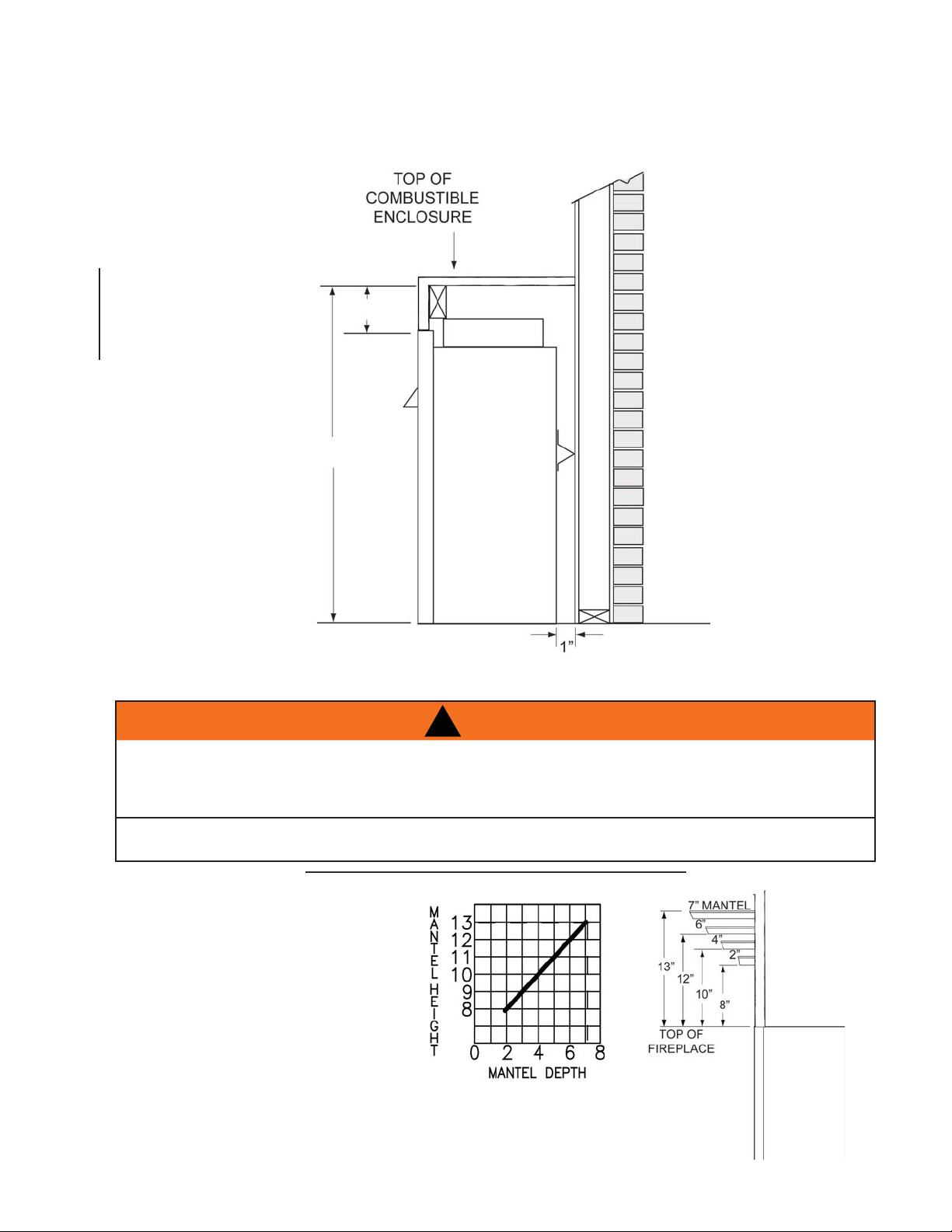
4.2 MINIMUM CLEARANCES TO COMBUSTIBLE ENCLOSURES
Combustible mantel clearance can vary
according to the mantel depth. Use the
graph to help evaluate the clearance
needed.
The appliance requires a minimum enclosure height of 39”. For temperature requirements, the enclosure space
around and above the appliance must be left unobstructed.
4.3 MINIMUM MANTEL CLEARANCES
!
WARNING
RISK OF FIRE, MAINTAIN ALL SPECIFIED AIR SPACE CLEARANCES TO COMBUSTIBLES. FAILURE
TO COMPLY WITH THESE INSTRUCTIONS MAY CAUSE A FIRE OR CAUSE THE APPLIANCE TO
OVERHEAT. ENSURE ALL CLEARANCES (I.E. BACK, SIDE, TOP, VENT, MANTEL, FRONT, ETC.) ARE
CLEARLY MAINTAINED.
WHEN USING PAINT OR LACQUER TO FINISH THE MANTEL, THE PAINT OR LACQUER MUST BE
HEAT RESISTANT TO PREVENT DISCOLOURATION.
73.1
6”
39”
13
W415-0297 / P / 02.03.12
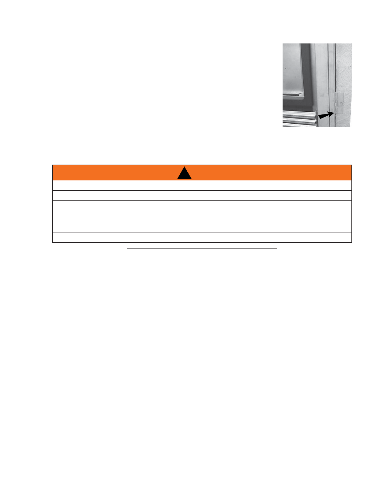
4.4 NAILING TAB INSTALLATION
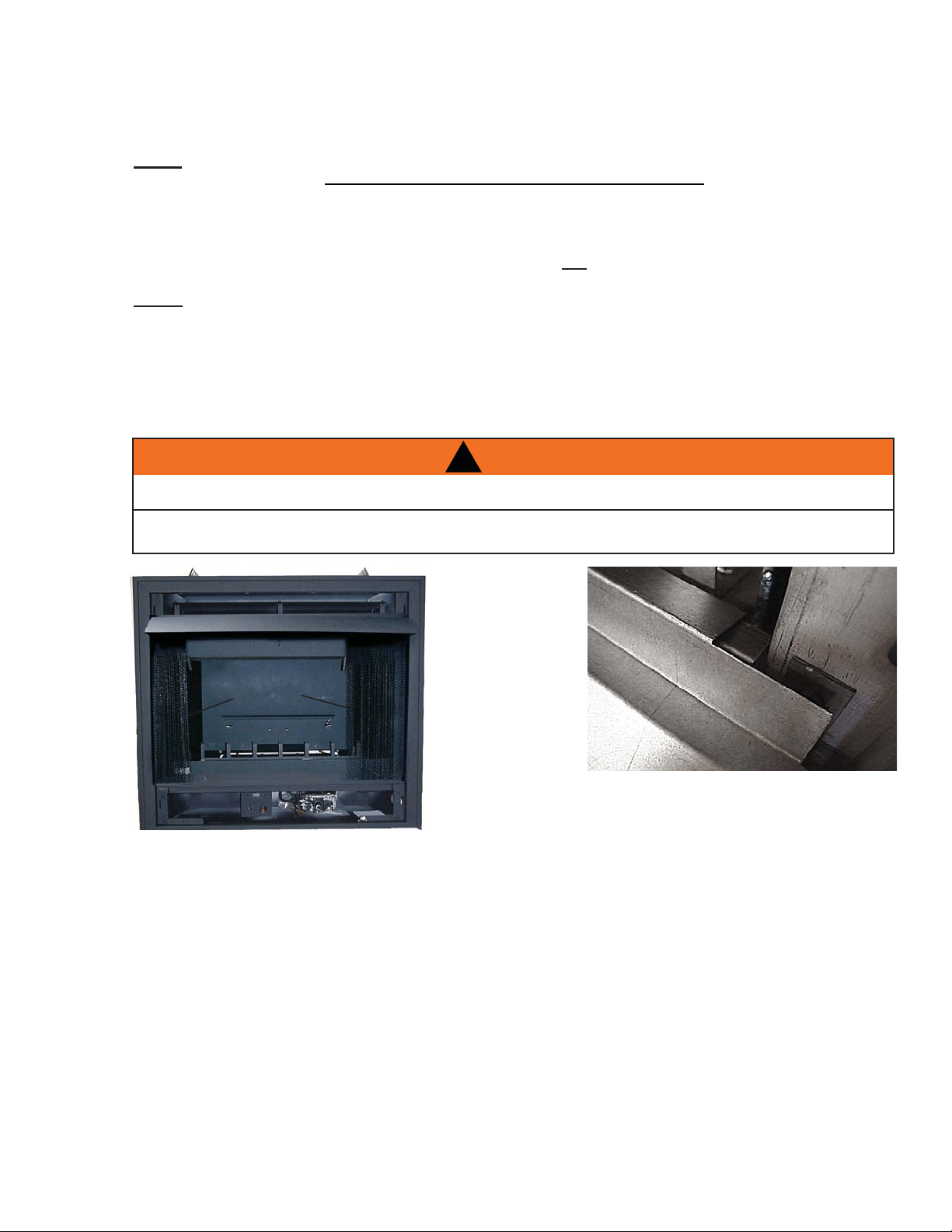
To install the appliance face fl ush with the fi nished wall, position the framework to
accommodate the thickness of the fi nished wall. Bend out the four nailing tabs,
attached on either side of the appliance and secure to the 2x4 framing. The tabs
will facilitate the installation of either a
3
/
4
” or a 1” fi nished wall thickness. The
nailing tabs must not be removed.
nailing
tab
!
WARNING
RISK OF FIRE!
NEVER OBSTRUCT THE FRONT OPENING OF THE APPLIANCE.
THE FRONT OF THE APPLIANCE MUST BE FINISHED WITH ANY NON-COMBUSTIBLE MATERIALS
SUCH AS BRICK, MARBLE, GRANITE, ETC., PROVIDED THAT THESE MATERIALS DO NOT GO
BELOW THE SPECIFIED DIMENSION AS ILLUSTRATED. AS AN ALTERNATIVE, YOU CAN FINISH THE
APPLIANCE WITH DRYWALL, SEE ILLUSTRATIONS TO FOLLOW.
FACING AND/OR FINISHING MATERIAL MUST NEVER OVERHANG INTO THE APPLIANCE OPENING.
72.2
5.0 FINISHING
14
W415-0297 / P / 02.03.12
Replacement loose material must be purchased from
the original manufacturer. Application of
excess loose material may adversely affect the
performance of the appliance.
Log colours may vary. During the initial use of the
appliance, the colours will become more uniform as
colour pigments burn in during the heat activated curing
process.
Reinstall rod assembly and mesh curtain.
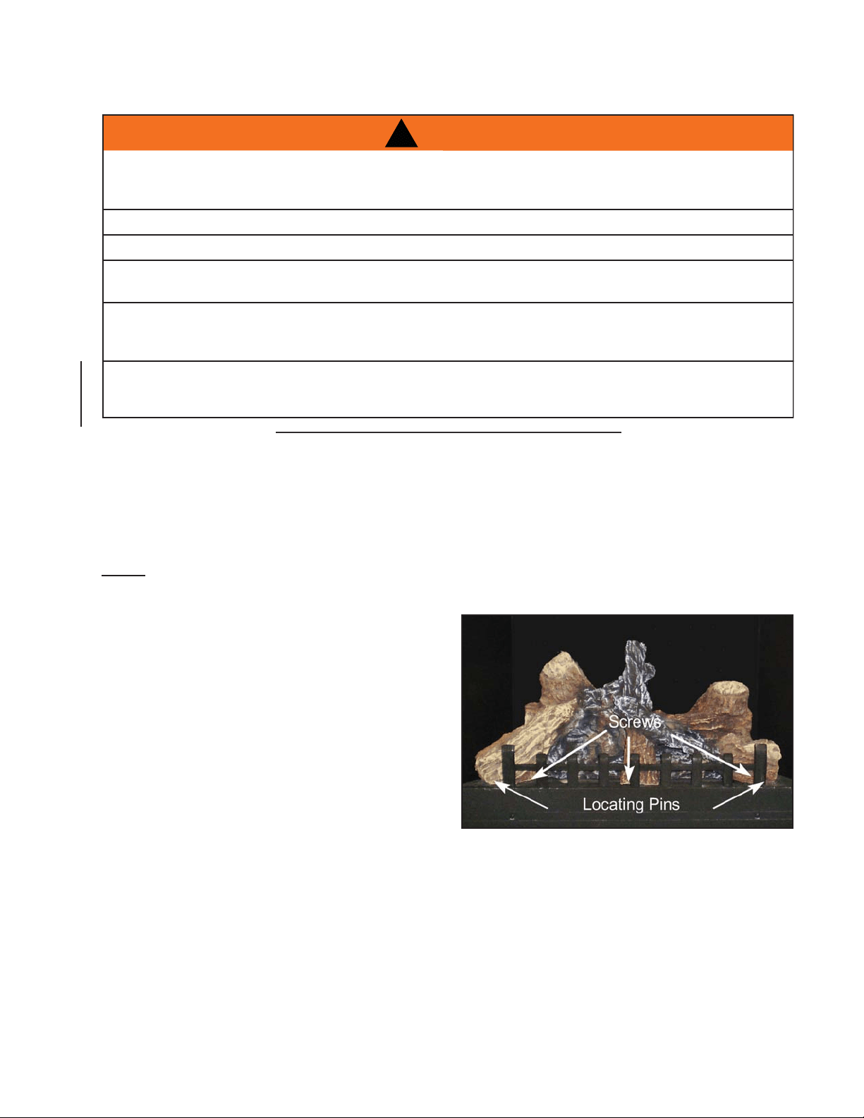
5.1 GRATE AND LOG PLACEMENT
Remove curtain mesh and rod assembly
Remove log carton
Remove grate from the lower control area (stored there when shipped)
Unscrew the 3 screws in the fi rebox, set grate in place and secure using the 3 screws that were just re-
moved.
Install the one piece log set by aligning the two holes on the bottom of the logs, with the two locating pins in the
fi rebox.
NOTE: PHAZER
TM
logs and glowing embers exclusive to Napoleon Fireplaces, provide a unique and
realistic glowing effect that is different in every installation. Take the time to carefully position the
glowing embers for a maximum glowing effect.
!
WARNING
LOGS MUST BE PLACED IN THEIR EXACT LOCATION IN THE APPLIANCE. DO NOT MODIFY THE
PROPER LOG POSITIONS, SINCE APPLIANCE MAY NOT FUNCTION PROPERLY. DELAYED IGNITION
AND CARBON / SOOT DISTRIBUTION THROUGHOUT THE LIVING AREA MAY OCCUR.
THE LOGS ARE FRAGILE AND SHOULD BE HANDLED WITH CARE.
DO NOT PLACE CHARCOAL EMBERS, VERMICULITE OR CHARCOAL LUMPS ON THIS BURNER.
ALL PREVIOUSLY APPLIED LOOSE MATERIAL (GLOWING EMBERS) MUST BE REMOVED PRIOR TO
REAPPLICATION.
DO NOT CHANGE OR SUBSTITUTE THE GLOWING EMBER MATERIAL PROVIDED WITH THE
APPLIANCE. IF REPLACING, USE ONLY REPLACEMENT GLOWING EMBERS AVAILABLE FROM
YOUR LOCAL AUTHORIZED DEALER / DISTRIBUTOR.
FAILURE TO FOLLOW THESE INSTRUCTIONS WILL ADVERSELY EFFECT THE APPLIANCE’S
PERFORMANCE AND MAY RESULT IN CARBON / SOOT DEPOSITS INSIDE THE APPLIANCE AND ON
SURROUNDING SURFACES.
76.2B
15
W415-0297 / P / 02.03.12
5.2 CHARCOAL EMBERS
32.1
Randomly place the charcoal embers along the front and sides of the log support tray in a realistic manner.
Fine dust found in the bottom of the bag should not be used.
NOTE: Charcoal embers are not to be placed on the burner.
5.3 GLOWING EMBERS
Tear the embers into pieces and place along the front row of ports covering all of the burner area in front of
the small logs. Care should be taken to shred the embers into thin, small irregular pieces as only the exposed
edges of the fi bre hairs will glow.
NOTE: The ember material will only glow when exposed to direct fl ame; however, care should be taken
to not block the burner ports.
Blocked burner ports can cause an incorrect fl ame pattern, carbon deposits and delayed ignition. PHAZER
TM
logs glow when exposed to direct fl ame. Use only certifi ed “glowing embers” and PHAZER
TM
logs available
from your Napoleon dealer.
HOOD
CURTAIN
MESH
!
WARNING
APPLIANCE SCREENS MUST BE CLOSED WHILE THE APPLIANCE IS IN OPERATION.
THE APPLIANCE MUST NOT BE USED WHEN THE HOOD IS REMOVED.
Hook the hood over the lip of the curtain support plate.
5.4 HOOD

16
W415-0297 / P / 02.03.12
!
WARNING
RISK OF FIRE AND ELECTRICAL SHOCK.
TURN OFF THE GAS AND ELECTRICAL POWER BEFORE SERVICING THIS APPLIANCE.
USE ONLY WOLF STEEL APPROVED OPTIONAL ACCESSORIES AND REPLACEMENT PARTS WITH
THIS APPLIANCE. USING NON-LISTED ACCESSORIES (BLOWERS, DOORS, LOUVRES, TRIMS, GAS
COMPONENTS, VENTING COMPONENTS, ETC.) COULD RESULT IN A SAFETY HAZARD AND WILL
VOID THE WARRANTY AND CERTIFICATION.
ENSURE THAT THE FAN’S POWER CORD IS NOT IN CONTACT WITH ANY SURFACE OF THE
APPLIANCE TO PREVENT ELECTRICAL SHOCK OR FIRE DAMAGE. DO NOT RUN THE POWER
CORD BENEATH THE APPLIANCE.
THE WIRE HARNESS PROVIDED IN THE BLOWER KIT IS A UNIVERSAL HARNESS. WHEN
INSTALLED, ENSURE THAT ANY EXCESS WIRE IS CONTAINED, PREVENTING IT FROM MAKING
CONTACT WITH MOVING OR HOT OBJECTS.
51.5
Remove the backing of the logo supplied and place on the screen cover, as
indicated.
A
B
C
SLOT
A
B
C
CLIPS
CENTRE SLOT
TAB
SLOT
HINGE CLIP
57.3
UPPER LOUVRES
Insert the louvre tabs
into the slots located
at the top left and right
corners of the unit.
LOWER LOUVRES
Insert the hinge clips
into the slots located at
the bottom left and right
corners of the unit. To
remove the louvres, pull
the back tabs of the clips
forward, while pushing
the louvre assembly
back. Lift the clip.
HOOD
Attach the hood by
pressing the top fl ange
into the clips along the
top of the louvre open-
ing. Secure using a
screw through the centre
slot.
5.5 LOUVRE INSTALLATION
5.6 LOGO PLACEMENT
6.0 OPTIONAL BLOWER INSTALLATION
17
W415-0297 / P / 02.03.12
INSTALLATION TO BE DONE BY A QUALIFIED INSTALLER and must
be electrically connected and grounded in accordance with local codes.
In the absence of local codes, use the current CSA C22.1 Canadian
electrical code in Canada or the ANSI / NFPA 70 National Electrical Code
in the United States.
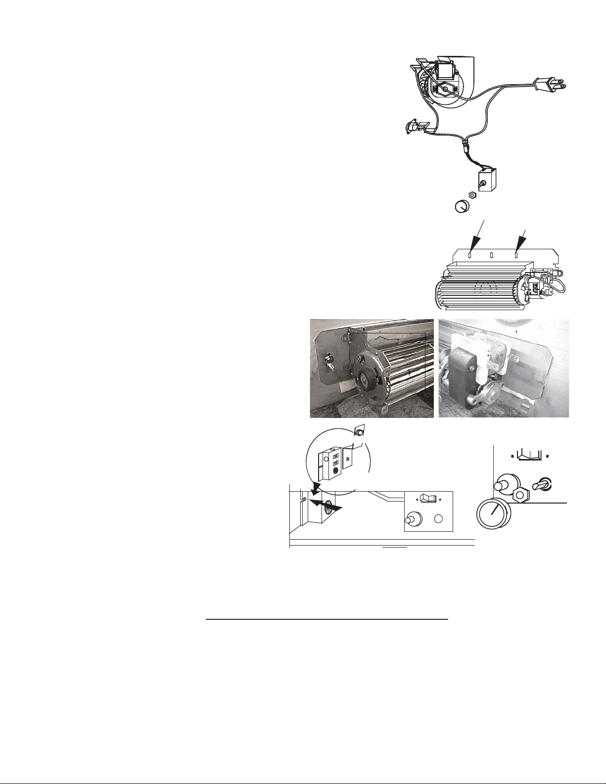
If the appliance was not previously equipped with a blower:
Route a grounded 2-wire, 60hz power cable to the receptacle /
junction box. At this point, it must be strain relieved and insulated.
The three slots on the blower mounting bracket allow ease of adjustment when
attaching the blower. For a quiet running blower, do not allow the assembly to
sit on the firebox base. Slide the vibration reducing pad (A) into the clip (C) and
up against the threaded stud (B) at the other end. The blower must be able to
be positioned entirely onto the pad.
To ease installation of the blower, remove the hinge screen and valve control door
(lower louvres) from the base of the appliance.
Tilt the blower onto its side. Slide it past the controls and into the clip (C).
Secure to the threaded stud using the lock washer and wing nut provided.
Ensure that the blower does not touch the appliance base or the firebox.
Attach the connectors from the black and white
wires to the thermal switch and secure the
thermal switch bracket to the bottom left of the unit
using the screws provided. Ensure that the
thermal switch touches the firebox wall.
Attach the connectors from the black and red
wires to the blower.
Attach and secure the variable speed switch
using the nut provided. Plug the harness cord
into the receptacle.The wire harness provided
in this kit is a universal harness. When installed,
ensure that any excess wire is contained,
preventing it from making contact with
moving or hot objects.
Because the blower is thermally activated,
when turned on, it will automatically start
approximately 10 minutes after lighting the appliance and will run for approximately 30-45 minutes after the
appliance has been turned off. Use of the fan increases the output of heat. Drywall dust will penetrate into the
blower bearings, causing irreparable damage. Care must be taken to prevent drywall dust from coming into
contact with the blower or its compartment. Any damage resulting from this condition is not covered by the
warranty policy.
black
white
red
VARIABLE
SPEED
SWITCH
BLOWER
THERMAL
SWITCH
SLOTS
ELONGATED
VARIABLE
SPEED
KNOB
A
B
C
51.1
RECEPTACLE /
THERMAL SWITCH
GROUND
SCREW
JUNCTION BOX
18
W415-0297 / P / 02.03.12
7.0 OPERATION
FOR YOUR SAFETY READ BEFORE LIGHTING:
Ɣ This appliance is equipped with a pilot which must be lit by hand while following these instructions exactly.
Ɣ
Before operating smell all around the appliance area for gas and next to the floor because some gas is heavier than air and will settle on the floor.
Ɣ Use only your hand to push in and turn the gas control knob. Never use tools. If the knob will not push in and turn by hand, do not try
to repair it. Call a qualified service technician. Force or attempted repair may result in a fire or explosion.
Ɣ Do not use this appliance if any part has been under water. Immediately call a qualified service technician to inspect the appliance
and replace any part of the control system and any gas control which has been under water.
ƔDo not try to light any appliance.
ƔDo not touch any electric switch; do not use any phone in your building.
Ɣ Immediately call your gas supplier from a neighbour’s phone. Follow the gas supplier’s instructions.
Ɣ If you cannot reach your gas supplier, call the fire department.
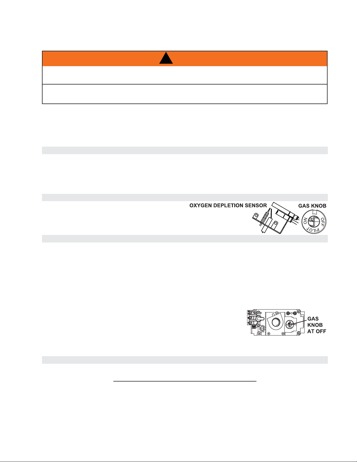
When lighting and re-lighting, the gas knob cannot be turned from pilot to off unless the knob is depressed.
$ STOP! Read the above safety information on this label.
% Set the thermostat to lowest setting.
& Turn off all electric power to the appliance.
' Open the control door. Turn the gas knob clockwise to off.
( Wait five (5) minutes to clear out any gas. If you smell gas including near the floor, STOP! Follow “B” in the above safety information
on this label. If you don’t smell gas go to the next step.
) Find pilot located in front of the back log.
G. Turn gas knob counter-clockwise to pilot.
H. Depress and hold gas knob while lighting the pilot with the push button ignitor. Keep knob fully depressed for one minute, then
release. If pilot does not continue to burn repeat steps 3 through 7.
, With pilot lit, turn gas knob counter-clockwise to on. When the pilot has been turned off,
ignition of the main burner may be delayed from 1-2 minutes. When the pilot has been left
burning, ignition of the main burner should occur almost immediatley.
- If equipped with remote on-off switch, main burner may not come on when you turn the valve to on. Remote switch must be in
the on position to ignite burner.
K. Turn on all electric power to the appliance.
A. Turn off all electric power to the appliance if service is to be performed.
%Push in gas control knob slightly and turn clockwise to off. Do not force.
WHAT TO DO IF YOU SMELL GAS:
LIGHTING INSTRUCTIONS:
TO TURN OFF GAS
,IDSSOLDQFHVKXWVRIIGRQRWUHOLJKWXQWLO\RXSURYLGHIUHVKDLU,IDSSOLDQFHNHHSVVKXWWLQJRIIKDYHLWVHUYLFHG.HHSEXUQHU
DQGFRQWUROFRPSDUWPHQWFOHDQ
When lit for the first time, the appliance will emit a slight odour for a few hours. This is a normal temporary condition caused by the curing
of the logs and the “burn-in” of internal paints and lubricants used in the manufacturing process and will not occur again. After extended
periods of non-operation such as following a vacation or a warm weather season, the appliance may emit a slight odour for a few hours.
This is caused by dust particles burning off. In both cases, open a window to sufficiently ventilate the room.
47.1
,)<28'2127)2//2:7+(6(,16758&7,216(;$&7/<$),5(25(;3/26,210$<5(68/7
&$86,1*3523(57<'$0$*(3(5621$/,1-85<25/2662)/,)(
,)$33/,&$%/($/:$<6/,*+77+(3,/27:+(7+(5)257+(),5677,0(25,)7+(*$66833/<+$6
581287:,7+7+(*/$66'22523(1('255(029('
!
WARNING
19
W415-0297 / P / 02.03.12
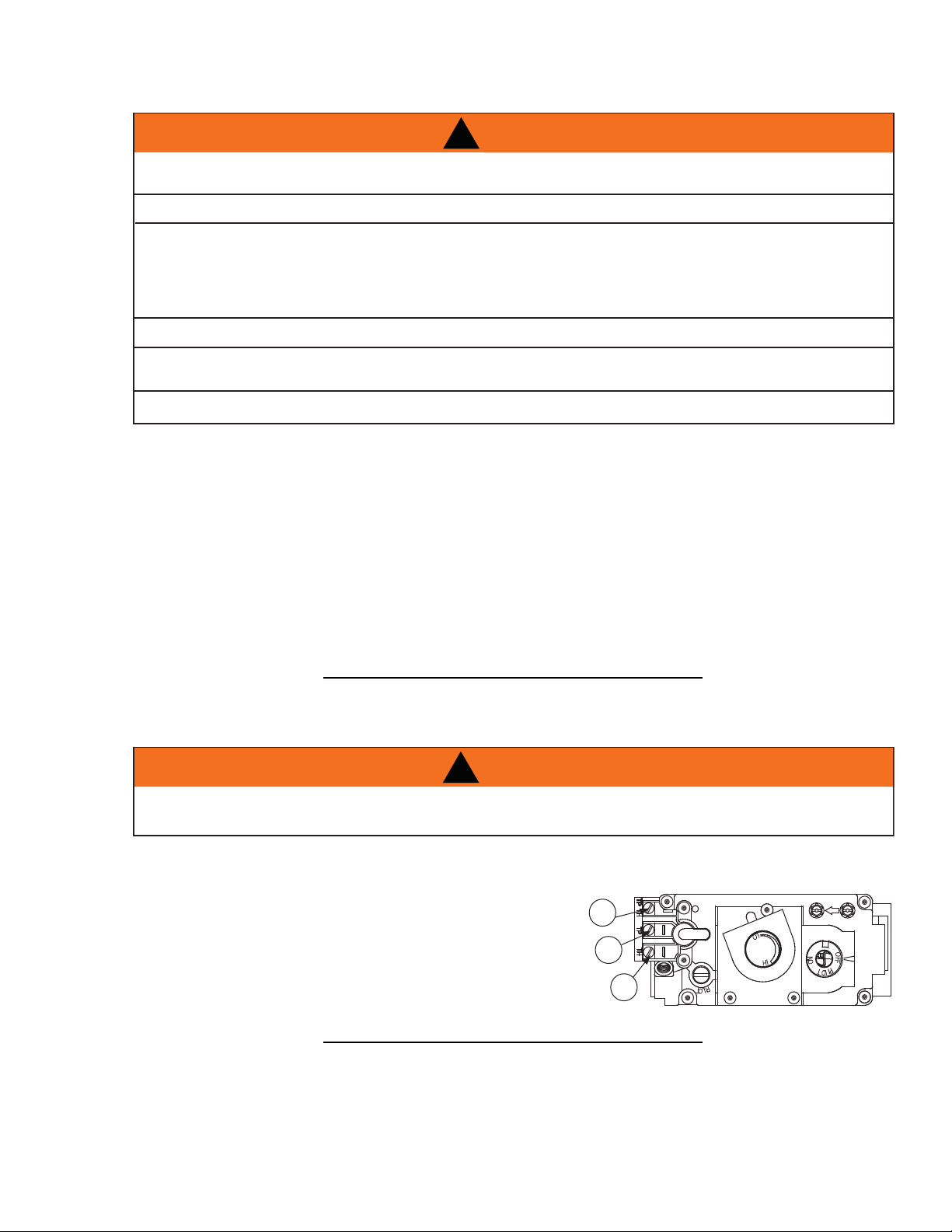
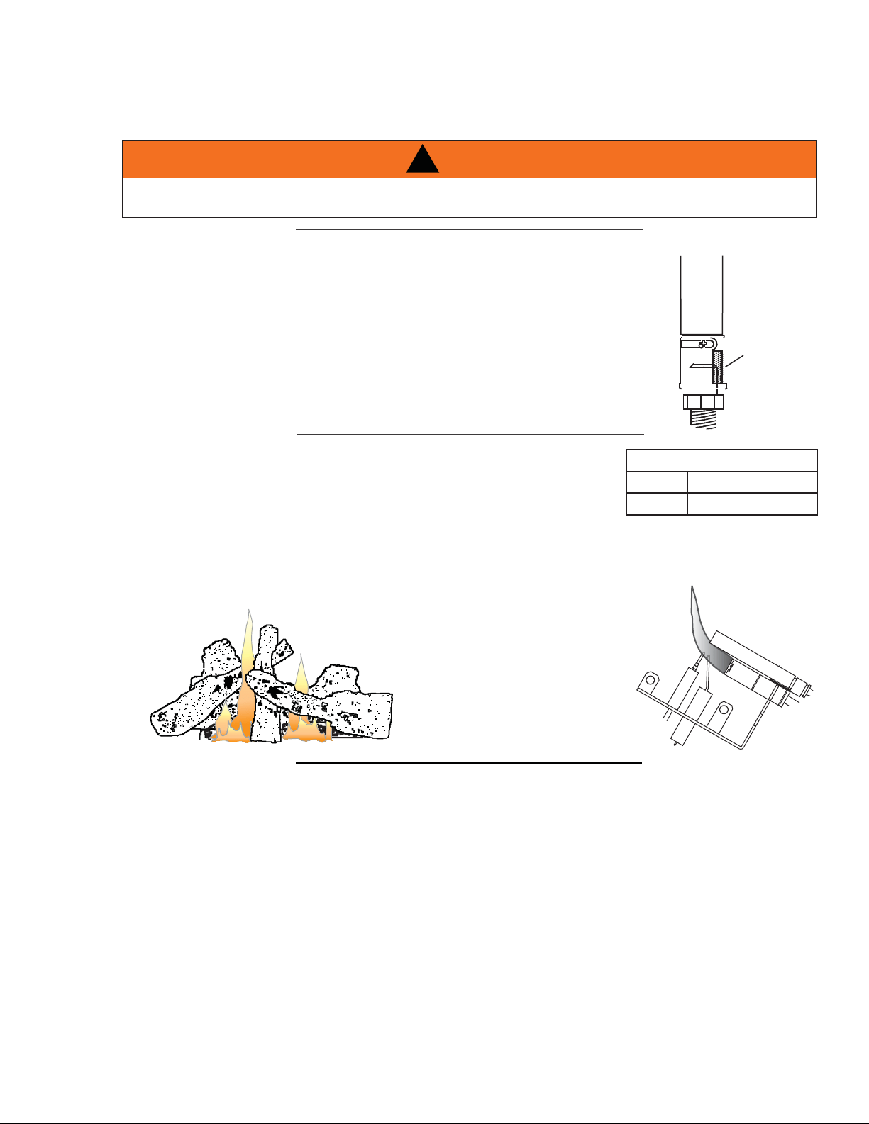
This appliance has an air shutter that has been factory set open according
to the chart below:
Regardless of venturi orientation, closing the air shutter will cause a more
yellow flame, but can lead to carboning. Opening the air shutter will cause a
more blue flame, but can cause flame lifting from the burner ports. The
flame may not appear yellow immediately; allow 15 to 30 minutes for the
final flame colour to be established.
AIR SHUTTER ADJUSTMENT MUST ONLY BE DONE BY A QUALIFIED
INSTALLER!
AIR
SHUTTER
OPENING
VENTURI
BURNER
ORIFICE
49.1
AIR SHUTTER OPENINGS
NG 3/16”
LP 1/2”
8.0 ADJUSTMENT
CARBON CAN BE DISTRIBUTED IN SURROUNDING LIVING AREA IF THE AIR SHUTTER IS
IMPROPERLY ADJUSTED.
!
WARNING
49.5
It’s important to periodically perform a visual check of the pilot and burner fl ames. Compare them to the illustra-
tions provided. If any fl ames appear abnormal call a service person.
54.5
8.1 VENTURI ADJUSTMENT
8.2 FLAME CHARACTERISTICS
20
W415-0297 / P / 02.03.12
This procedure must be performed by a
qualified service person!
Inspect the pilot for any visible
contamination or debris (usually lint, pet
hair, spider webs, carpet fibre, etc.) and remove.
Disconnect the pilot from the pilot tubing line,
using a 7/16” wrench. Blow out the housing in
the same direction as the gas flow. Re-install
the pilot tube, turn on the gas and check
for leaks.
If this does not improve the performance,
replace the ODS with an exact replacement. The
device is tamper resistant with no field serviceable
parts.
CORRECT PILOT FLAME
(Clean, stable, pronounced
blue flame).
INCORRECT PILOT FLAME
(Flame lifts upwards,
becomes unstable with more
of an orange tip).
46.1
6.1
If the appliance is equipped with plated parts, you must clean fi ngerprints or other marks from the plated
surfaces before operating the appliance for the fi rst time. Use a glass cleaner or vinegar and towel to clean.
If not cleaned properly before operating for the fi rst time, the marks can cause permanent blemishes on
the plating. After the plating is cured, the fi ngerprints and oils will not affect the fi nish and little maintenance
is required, just wipe clean as needed. Prolonged high temperature burning with the door ajar may cause
discolouration on plated parts.
NOTE: The protective wrap on plated parts is best removed when the assembly is at room
temperature but this can be improved if the assembly is warmed, using a hair dryer or similar heat
source.
9.0 MAINTENANCE
CAUTION: Label all wires prior to disconnection when servicing controls. Wiring errors can cause improper
and dangerous operation. Verify proper operation after servicing. This appliance and its venting system
should be inspected before use and at least annually by a qualifi ed service person. The appliance area must
be kept clear and free of combustible materials, gasoline or other fl ammable vapors and liquids. The fl ow of
combustion and ventilation air must not be obstructed.
1. In order to properly clean the burner and pilot assembly, remove the logs, rocks and/or glass to
expose both assemblies.
2. Keep the control compartment, media, burner, air shutter opening and the area surrounding the logs
clean by vacuuming or brushing, at least once a year.
3. Check to see that all burner ports are burning. Clean out any of the ports which may not be burning or
are not burning properly.
4. Check to see that the pilot fl ame is large enough to engulf the fl ame sensor and/or thermocouple /
thermopile as well as reaches the burner.
5. Replace the cleaned logs, rocks or glass. Failure to properly position the media may cause carboning
which can be distributed in the surrounding living area.
6. Check to see that the main burner ignites completely on all openings when turned on. A 5 to 10
second total light-up period is satisfactory. If ignition takes longer, consult your local authorized dealer /
distributor.
40.16
MAINTENANCE
MAINTENANCE
MAINTENANCE
TURN OFF THE GAS AND ELECTRICAL POWER BEFORE SERVICING THE APPLIANCE.
APPLIANCE MAY BE HOT, DO NOT SERVICE UNTIL APPLIANCE HAS COOLED.
DO NOT USE ABRASIVE CLEANERS.
!
WARNING
9.1 OXYGEN DEPLETION SENSOR PILOT CLEANING
9.2 CARE OF PLATED PARTS
21
W415-0297 / P / 02.03.12
10.0 REPLACEMENTS
Contact your dealer or the factory for questions concerning prices and policies on replacement parts. Normally
all parts can be ordered through your Authorized dealer / distributor.
FOR WARRANTY REPLACEMENT PARTS, A PHOTOCOPY OF THE ORIGINAL INVOICE WILL BE
REQUIRED TO HONOUR THE CLAIM.
When ordering replacement parts always give the following information:
• Model & Serial Number of appliance
• Installation date of appliance
• Part number
• Description of part
• Finish
* IDENTIFIES ITEMS WHICH ARE NOT ILLUSTRATED. FOR
FURTHER INFORMATION, CONTACT YOUR AUTHORIZED DEALER.
41.1
FAILURE TO POSITION THE PARTS
IN ACCORDANCE WITH THIS
MANUAL OR FAILURE TO USE ONLY
PARTS SPECIFICALLY APPROVED
WITH THIS APPLIANCE MAY
RESULT IN PROPERTY DAMAGE OR
PERSONAL INJURY.
!
WARNING
COMPONENTS
REF PART NO. DESCRIPTION
1 W357-0001 PIEZO IGNITER
2 W662-0001 OXYGEN DEPLETION SENSOR SYSTEM - NG
2 W662-0005 OXYGEN DEPLETION SENSOR SYSTEM - LP
3* W680-0004 THERMOPILE
4 W725-0030 NATURAL GAS VALVE
4 W725-0031 PROPANE GAS VALVE
5* W385-0334 NAPOLEON LOGO
6* W750-0112 20FT OF WIRE
7 GL-664 ONE PIECE LOG SET (W135-0335)
8* W361-0016 GLOWING EMBERS
9* W550-0001 CHARCOAL EMBERS
10 W010-0764 PAN BURNER (NG)
10 W010-0987 PAN BURNER (LP)
11 W456-0039 #39 NATURAL GAS BURNER ORIFICE
11 W456-0053 #53 PROPANE GAS BURNER ORIFICE
12 W335-0050 HOOD
13 W565-0058 CURTAIN MESH
14 W555-0033 CURTAIN ROD
15* W080-0742 CURTAIN ROD BRACKET
16 W500-0194 PLATE COVER
17 W630-0010 BLACK TASSELS
ACCESSORIES
REF PART NO. DESCRIPTION
18* W660-0081 SWITCH, THERMOSTAT
19* F40 ON/OFF REMOTE
19* F50 THERMOSTATIC REMOTE
19* F50DR DESIGNER THERMOSTATIC REMOTE - RED
19* F50DY DESIGNER THERMOSTATIC REMOTE - GREY
19* F50DK DESIGNER THERMOSTATIC REMOTE - BLACK
20* W660-0013 MODULATING REMOTE
21* GD825N MODULATING REGULATOR NG
21* GD825P MODULATING REGULATOR LP
22* W660-0026 PROGRAMMABLE TIMER, BATTERY OPERATED
23 GZ550-1KT BLOWER KIT
24* W500-0033 VARIABLE SPEED SWITCH WALL MOUNTING PLATE
25* 111KT OUTSIDE AIR KIT
26* 112KT ADAPTOR PLATE FOR OUTSIDE AIR KIT
27 HOIK-3 ORNAMENTAL INSETS - BLACK
27 HOIG-3 ORNAMENTAL INSETS - GOLD
27 HOISS-3 ORNAMENTAL INSETS - SATIN CHROME
22
W415-0297 / P / 02.03.12
27
1
23
10
4
11
28
2
16
17
14
12
13
7
7
35
34
36
28 L36K LOUVRE KIT, BLACK
28 L36PB LOUVRE KIT, POLISHED BRASS
28 L36AB LOUVRE KIT, ANTIQUE BRASS
28 L3SS LOUVRE KIT, STAINLESS STEEL
29* GD36B-KT BAY FRONT
30* GDBLK BAY LOUVRE KIT, UPPER AND LOWER - BLACK
30* GDBLSS BAY LOUVRE KIT, UPPER AND LOWER - STAINLESS STEEL
31* GDBOIK BAY ORNAMENTAL INSET - HERITAGE UPPER AND LOWER - BLACK
32* GV824KT DECORATIVE BRICK PANELS - SANDSTONE
33* MBP36VF METAL BRICK PANELS
34 PRP36VF PORCELAIN REFLECTIVE RADIANT PANELS
35 TB336K BEVELLED TRIM KIT - 3” (COVERS OPENING 37” W X 33” H) - TEXTURED BLACK
35 TB336AB BEVELLED TRIM KIT - 3” (COVERS OPENING 37” W X 33” H) - ANTIQUE BRASS
35 TB336PB BEVELLED TRIM KIT - 3” (COVERS OPENING 37” W X 33” H) - POLISHED BRASS
35 TB336SS BEVELLED TRIM KIT - 3” (COVERS OPENING 37” W X 33” H) - STAINLESS STEEL
35 TB636K BEVELLED TRIM KIT - 6” (COVERS OPENING 44” W X 36” H) - TEXTURED BLACK
35 TB636AB BEVELLED TRIM KIT - 6” (COVERS OPENING 44” W X 36” H) - ANTIQUE BRASS
35 TB636SS BEVELLED TRIM KIT - 6” (COVERS OPENING 44” W X 36” H) - STAINLESS STEEL
36 CFSK-A CAST IRON SURROUND KIT (COVERS OPENING 44” W X 36” H) PAINTED BLACK
36 CFSKN-A CAST IRON SURROUND KIT (COVERS OPENING 44” W X 36” H) PORCELAIN MAJOLICA BROWN
37* ANI-K ANDIRONS - PAINTED BLACK

23
W415-0297 / P / 02.03.12
11.0 TROUBLE SHOOTING GUIDE
SYMPTOM PROBLEM TEST SOLUTION
Main burner goes
out; pilot stays on.
Pilot fl ame is not large
enough or not engulfi ng
the thermopile.
- Ensure adequate supply pressure.
- Replace pilot assembly.
Thermopile shorting /
loose connection.
- Clean thermopile connection to the valve.
Reconnect.
- Replace thermopile / valve.
Remote wall switch wire
is too long; too much
resistance in the system.
- Shorten wire to connect length or wire gauge.
Faulty thermostat or
switch.
- Replace.
Main burner goes
out; pilot goes out.
Insuffi cient air supply. - Open window or door. (Use one of the methods
described in ANSI Z223.1 / NFPA54 or the
applicable local code.)
- Have room checked for adequate air exchange.
- See “COMBUSTION AND VENTILATION AIR
PROVISIONS” section to ensure adequate air supply.
Out of propane gas. - Fill the tank.
Pilot fl ame is not large
enough. (Supply pressure
too low.)
- Service or replace Oxygen Depletion Sensor
System.
- Correct piping and / or regulator to provide correct
pressure.
- Ensure adequate supply pressure.
Pilot goes out
when the gas knob
is released.
The gas valve has
an interlock device
which will not allow
the pilot burner
to be lit until the
thermocouple
has cooled. Allow
approximately 60
seconds for the
thermocouple to
cool.
System is not correctly
purged.
- Purge the gas line.
Out of propane gas. - Fill the tank.
Pilot fl ame is not large
enough. (Supply pressure
too low.)
- Service or replace Oxygen Depletion Sensor
System.
Thermocouple shorting /
faulty.
- Loosen and tighten thermocouple.
- Clean thermocouple and valve connection.
- Replace Oxygen Depletion Sensor System.
- Test and replace valve.
Faulty valve / high low
knob does not depress
smoothly.
- Replace.
42.4_A
!
WARNING
ALWAYS LIGHT THE PILOT WHETHER FOR THE FIRST TIME OR IF THE GAS SUPPLY HAS RAN OUT,
WITH THE GLASS DOOR OPEN OR REMOVED.
TURN OFF THE GAS AND ELECTRICAL POWER BEFORE SERVICING THE APPLIANCE.
APPLIANCE MAY BE HOT, DO NOT SERVICE UNTIL APPLIANCE HAS COOLED.
DO NOT USE ABRASIVE CLEANERS.
24
W415-0297 / P / 02.03.12
SYMPTOM PROBLEM TEST SOLUTION
Pilot burning;
no gas to main
burner; gas
knob is on ‘HI’;
wall switch /
thermostat is on.
Thermostat or switch is
defective.
- Connect a jumper wire across the wall switch
terminals; if main burner lights, replace switch /
thermostat.
Wall switch wiring is
defective.
- Disconnect wires from valve. Connect a jumper wire
across terminals 1 & 3; if the main burner lights,
check the wires for defects and / or replace wires.
Main burner orifi ce is
plugged.
- Remove stoppage in orifi ce.
Faulty valve. - Replace.
Pilot will not light. Out of propane gas. - Fill the tank.
No spark at pilot burner. - Check if pilot can be lit by a match.
- Check that the wire is connected to the push button
ignitor.
- Check if the push button ignitor needs tightening.
- Replace the wire if the wire insulation is broken or
frayed.
- Replace the electrode if the ceramic insulator is
cracked or broken.
- Replace the push button ignitor.
No gas at the pilot burner. - Check that the manual valve is turned on.
- Check the pilot orifi ce for blockage.
- Replace the valve / Oxygen Depletion Sensor
System.
- Call the gas distributor.
Pilot goes out
while standing;
Main burner is in
‘OFF’ position.
Gas piping is undersized. - Turn on all gas appliances and see if pilot fl ame
fl utters, diminishes or extinguishes, especially
when main burner ignites. Monitor appliance supply
working pressure.
- Check if supply piping size is to code. Correct all
undersized piping.
Pilot fl ame is not large
enough.
- ODS Burner requires checking.
Main burner will
not light; or is slow
to light, noisy pilot.
Inlet pressure too high. - Adjust inlet pressure to ensure maximum 7.0” W.C.
at gas valve for natural gas and 13.0” W.C. for
propane.
Pilot fl ame blowing off,
missing thermopile.
Carbon is being
deposited on
glass, logs,
rocks, media
or combustion
chamber.
Air shutter has become
blocked.
- Ensure air shutter opening is free of lint or other
obstructions.
Flame is impinging on the
glass, logs, rocks, media
or combustion chamber.
- Check that the logs are correctly positioned.
- Check for ceiling or oscillating fans that may be
infl uencing the fl ame.
- Open air shutter to increase the primary air. See
“VENTURI ADJUSTMENT” section.
- Check the input rate: check the manifold pressure
and ori
fi ce size as specifi ed by the rating plate.
42.4_2_A
ELECTRODE
THERMOCOUPLE
THERMOPILE
PILOT
BURNER
* Check for ceiling or oscillating fans that maybe infl uencing the fl ame. Ceiling fans or oscillating type fl oor fans can cause
fl ame impingement if directing air at the appliance. Impinging fl ames will cause soot or carbon that may enter into living
area. Try reversing ceiling fan or re-directing fl oor fans to prevent sooting.
25
W415-0297 / P / 02.03.12
SYMPTOM PROBLEM TEST SOLUTION
Flames are
consistently too
large or too small.
Carboning occurs.
Unit is over-fi red or under-
fi red.
- Check pressure readings:
- Inlet pressure can be checked by turning screw (A)
counter-clockwise 2 or 3 turns and then placing
pressure gauge tubing over the test point. Check
with burner operating on “HI”. Gauge should read 7”
(minimum 4.5”) water column for natural gas or 13”
(11” minimum) water column for propane.
- Outlet pressure can be checked the same as above
using screw (B). Check with burner operating on
“HI”. Gauge should read 3.5” water column for
natural gas or 10” water column for propane.
- AFTER TAKING PRESSURE READINGS, BE
SURE TO TURN SCREWS CLOCKWISE FIRMLY
TO RESEAL. DO NOT OVER TORQUE.
- Leak test with a soap and water solution.
Air shutter improperly
adjusted.
- Return air shutter to specifi ed opening, see
“VENTURI ADJUSTMENT” section.
Exhaust fumes
smelled in room,
headaches.
Not enough combustion
air.
- Increase fresh air supply. (Use one of the methods
described in ANSI Z223.1 / NFPA 54 or the
applicable local code.)
Not enough ventilation air. - Increase fresh air supply. (Use one of the methods
described in ANSI Z223.1 / NFPA 54 or the
applicable local code.)
Flame is impinging on
the logs or combustion
chamber.
- Check that the logs are correctly positioned.
- Open air shutter to increase the primary air. See
“VENTURI ADJUSTMENT” section.
- Check the input rate: check the manifold pressure
and orifi ce size as specifi ed by the rating plate
values.
Remote wall
switch is in “off”
position; main
burner comes on
when gas knob
is turned to “ON”
position.
Wall switch is mounted
upside down.
- Reverse.
Remote wall switch is
grounding.
- Replace.
Remote wall switch wire is
grounding.
- Check for ground (short); repair ground or replace
wire.
Faulty valve. - Replace.
If optional catalytic
door is used,
White / grey fi lm
forms on the
glass.
Sulphur from fuel is being
deposited on the glass,
logs, rocks, media or
combustion surfaces.
- Clean glass with recommended gas appliance glass
cleaner. DO NOT CLEAN GLASS WHEN HOT!
- If deposits are not cleaned off regularly, the glass
may become permanently market.
42.4_3_A
P
I
P
I
L
O
T
N
O
L
O
T
H
I
L
O
F
F
O
A
B
PILOT SCREW

26
W415-0297 / P / 02.03.12
NAPOLEON® warrants its products against manufacturing defects to the original purchaser only. Registering your warranty is not necessary. Simply
provide your proof of purchase along with the model and serial number to make a warranty claim. NAPOLEON® reserves the right to have its
representative inspect any product or part thereof prior to honouring any warranty claim. Provided that the purchase was made through an authorized
NAPOLEON® dealer your appliance is subject to the following conditions and limitations:
Warranty coverage begins on the date of original installation.
This factory warranty is non-transferable and may not be extended whatsoever by any of our representatives.
The gas appliance must be installed by a licensed, authorized service technician or contractor. Installation must be done in accordance with the installation
instructions included with the product and all local and national building and fi re codes.
This limited warranty does not cover damages caused by misuse, lack of maintenance, accident, alterations, abuse or neglect and parts installed from
other manufacturers will nullify this warranty.
This limited warranty further does not cover any scratches, dents, corrosion or discoloring caused by excessive heat, abrasive and chemical cleaners nor
chipping on porcelain enamel parts, mechanical breakage of PHAZER™ logs and embers.
This warranty extends to the repair or replacement of warranted parts which are defective in material or workmanship provided that the product has been
operated in accordance with the operation instructions and under normal conditions.
After the fi rst year, with respect to this President’s Lifetime Limited Warranty, NAPOLEON® may, at its discretion, fully discharge all obligations with
respect to this warranty by refunding to the original warranted purchaser the wholesale price of any warranted but defective part(s).
NAPOLEON® will not be responsible for installation, labour or any other expenses related to the reinstallation of a warranted part and such expenses are
not covered by this warranty.
Notwithstanding any provisions contained in the President’s Lifetime Limited Warranty, NAPOLEON’S responsibility under this warranty is defi ned as
above and it shall not in any event extend to any incidental, consequential or indirect damages.
This warranty defi nes the obligations and liability of NAPOLEON® with respect to the NAPOLEON® gas appliance and any other warranties expressed or
implied with respect to this product, its components or accessories are excluded.
NAPOLEON® neither assumes, nor authorizes any third party to assume, on its behalf, any other liabilities with respect to the sale of this product.
NAPOLEON® will not be responsible for: over-fi ring, downdrafts, spillage caused by environmental conditions such as rooftops, buildings, nearby trees,
hills, mountains, inadequate vents or ventilation, excessive venting confi gurations, insuffi cient makeup air, or negative air pressures which may or may not
be caused by mechanical systems such as exhaust fans, furnaces, clothes dryers, etc.
Any damages to the appliance, combustion chamber, heat exchanger, plated trim or other components due to water, weather damage, long periods of
dampness, condensation, damaging chemicals or cleaners will not be the responsibility of NAPOLEON®.
All parts replaced under the President’s Limited Lifetime Warranty Policy are subject to a single claim.
During the fi rst 10 years NAPOLEON® will replace or repair the defective parts covered by the lifetime warranty at our discretion free of charge. From 10
years to life, NAPOLEON® will provide replacement parts at 50% of the current retail price.
All parts replaced under the warranty will be covered for a period of 90 days from the date of their installation.
The manufacturer may require that defective parts or products be returned or that digital pictures be provided to support the claim. Returned products are
to be shipped prepaid to the manufacturer for investigation. If a product is found to be defective, the manufacturer will repair or replace such defect.
Before shipping your appliance or defective components, your dealer must obtain an authorization number. Any merchandise shipped without
authorization will be refused and returned to sender.
Shipping costs are not covered under this warranty.
Additional service fees may apply if you are seeking warranty service from a dealer.
Warranty labour allowance is only for the replacement of the warranted part. Travel, diagnostic tests, shipping and other related charges are not covered
by this warranty.
2.1B
NAPOLEON® products are manufactured under the strict Standard of the world recognized ISO 9001 : 2008 Quality Assurance
Certifi cate.
NAPOLEON® products are designed with superior components and materials assembled by trained craftsmen who take great
pride in their work. The burner and valve assembly are leak and test-fi red at a quality test station. The complete appliance is
again thoroughly inspected by a qualifi ed technician before packaging to ensure that you, the customer, receives the quality
product that you expect from NAPOLEON®.
The following materials and workmanship in your new NAPOLEON® gas appliance are warranted against defects for as long as
you own the appliance. This covers: combustion chamber, heat exchanger, stainless steel burner, phazer™ logs and embers, rocks,
ceramic glass (thermal breakage only), gold plated parts against tarnishing, porcelainized enameled components and aluminum
extrusion trims.*
Electrical (110V and millivolt) components and wearable parts such as blowers, gas valves, thermal switch, switches, wiring, remote
controls, ignitor, gasketing, and pilot assembly are covered and NAPOLEON® will provide replacement parts free of charge during
the fi rst year of the limited warranty.*
Labour related to warranty repair is covered free of charge during the fi rst year. Repair work, however, requires the prior approval of
an authorized company offi cial. Labour costs to the account of NAPOLEON® are based on a predetermined rate schedule and any
repair work must be done through an authorized NAPOLEON® dealer.
* Construction of models vary. Warranty applies only to components included with your specifi c appliance.
NAPOLEON® GAS APPLIANCE PRESIDENT’S LIFETIME LIMITED WARRANTY
CONDITIONS AND LIMITATIONS
ALL SPECIFICATIONS AND DESIGNS ARE SUBJECT TO CHANGE WITHOUT PRIOR NOTICE DUE TO ON-GOING PRODUCT
IMPROVEMENTS. NAPOLEON® IS A REGISTERED TRADEMARK OF WOLF STEEL LTD.
12.0 WARRANTY
27
W415-0297 / P / 02.03.12
13.0 SERVICE HISTORY
43.1

28
W415-0297 / P / 02.03.12
44.1
14.0 NOTES