Loading ...
Loading ...
Loading ...
6
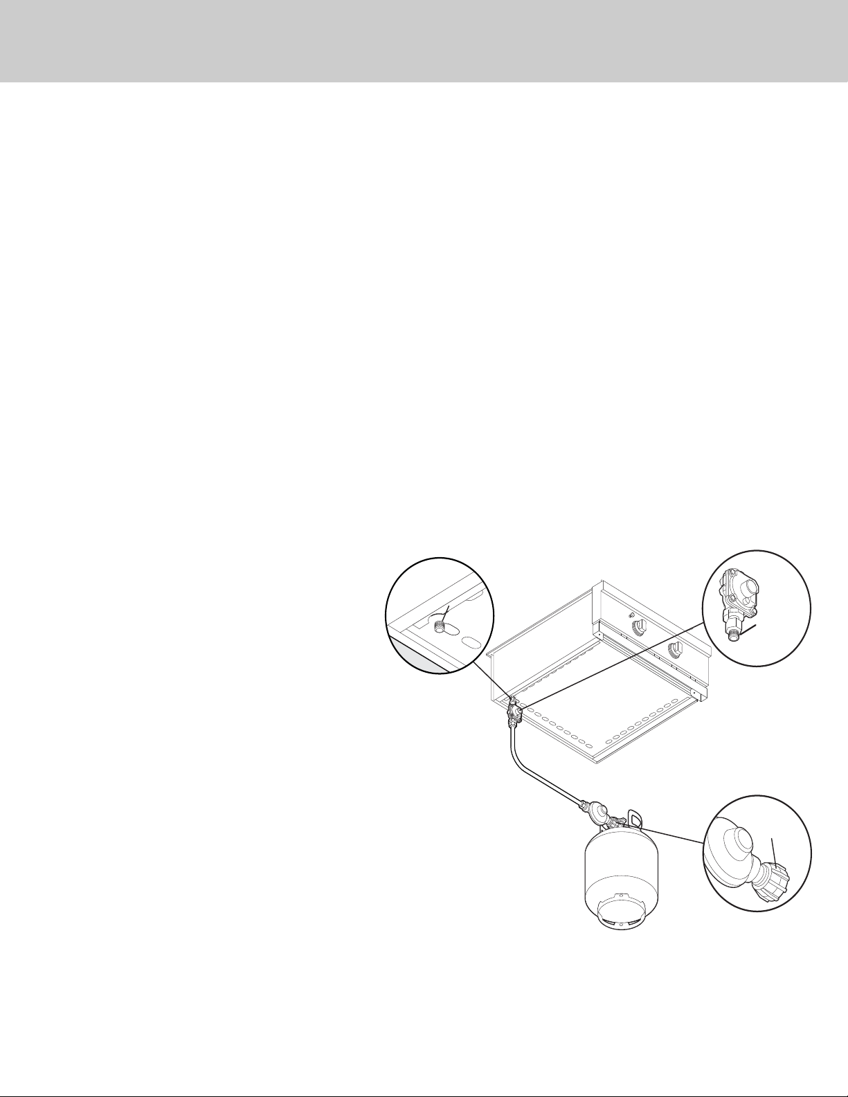
LP/Propane Tank Connection
Outdoor side burners orificed for use with LP/Propane gas come equipped with a high capacity hose/regulator assembly
for connection to a standard 20 lb. LP/Propane cylinder equipped with a Type 1, QCC-1 connector. (See LP/Propane tank
requirements on page 6). Hose assembly must comply with Elastomeric Composite Hose and Couplings for Conducting
Propane and Natural Gas, CAN/CGA-8.1 standard or the Thermoplastic Hose and Hose Couplings for Conducting
Propane and Natural Gas CAN1-8.3 standard. (See LP/Propane tank requirements below). Each tank is supplied with a
dust cap. Place dust cap on cylinder valve outlet whenever the cylinder is not in use. Only install the type of dust cap on
the cylinder valve outlet that is provided with the cylinder valve. Other types of caps or plugs may result in leakage of
propane.
Built-in installations must be plumbed using a fixed/hard line if the unit is going to be operated at a distance exceeding
3 feet (0.91 meters) from the fuel supply per ANSI Z21.24. Also, in a built-in construction where an LP/Propane tank is
going to be used, there MUST be some type of support (braces, cut-out, etc.) to prevent tank from moving within the
installation. The support must also allow the LP/Propane tank to withstand a horizontal tipping force equal to the weight
of the tank without tipping over. The tank can not tip over or deflect more than 1.00 inch when a 38 lb. horizontal force
is applied to a 20 lb. LP/Propane tank.
Connection: 1/2” (1.3 cm) NPT male with a 3/8” (.95) flare adapter
Operating Pressure: 10.0” W.C.P.
To connect to LP/Propane regulator/hose assembly:
You should always turn the LP/Propane tank main valve “OFF” after each use and during transport of the tank or unit.
First connect the regulator assembly to the grill unit. Connect to the tank valve by screwing the Type 1, QCC-1 connector
to the LP/Propane tank. Open the tank valve and check the connection between the regulator and the Type 1, QCC-1
fitting for leaks with a soapy water solution. If bubbles appear, tighten the connection. Repeat until all leaks have been
stopped. ALWAYS CHECK FOR LEAKS AFTER EVERY LP/PROPANE TANK CHANGE. Any joint sealant used must be an
approved type and be resistive to the actions of LP/Propane gas.
LP/Propane Tank Requirements
A dented or rusty LP/Propane tank may be hazardous
and should be checked by your tank supplier. Never
use a cylinder with a damaged valve. All tanks should
be equipped with an OPD (overfilling protection
device). This is a DOT requirement for all tanks
purchased after October 1, 1998 and will ensure that
the tank is not overfilled. The LP/Propane tank should
be a standard 5-gal, 20 lb. gas cylinder tank
approximately 12” in diameter and 18” high which
must be constructed and marked in accordance with
the Specifications for LP/Propane Gas Cylinders of the
U.S. Department of Transportation (D.O.T.) or the
National Standard of Canada, CAN/CSA-B339,
Cylinders, Spheres and Tubes for Transportation of
Dangerous Goods; and Commission. The cylinder
connection device must be compatible with the Type 1,
QCC-1 connector on the outdoor cooking appliance.
All LP/Propane tanks must be mounted in a vertical
position for proper ventilation. The cylinder must be
provided with a shut-off valve terminating in an
LP/Propane gas supply cylinder valve outlet specified.
The cylinder supply system must be arranged for vapor
withdrawal and provided with a listed overfilling
prevention device. If the appliance is stored indoors
the cylinder must be disconnected and removed from
the appliance. Each tank is supplied with a dust cap.
Place dust cap on cylinder valve outlet whenever the cylinder is not in use. Only install the type of dust cap on the cylinder valve
outlet that is provided with the cylinder valve. Other types of caps or plugs may result in leakage of propane. Cylinders must
be stored outdoors in a well-vented area out of the reach of children.
3/8” 3/8”
male male
flare flare
adapteradapter
1/2”
NPT
from
Manifold
Type 1,
QCC-1
connector
3/8” male
flare adapter
Regulator
Assembly
NOTE: Tank must be
mounted in vertical position
for proper Ventilation
Loading ...
Loading ...
Loading ...