MULTI
F
MAX
MULTI
F
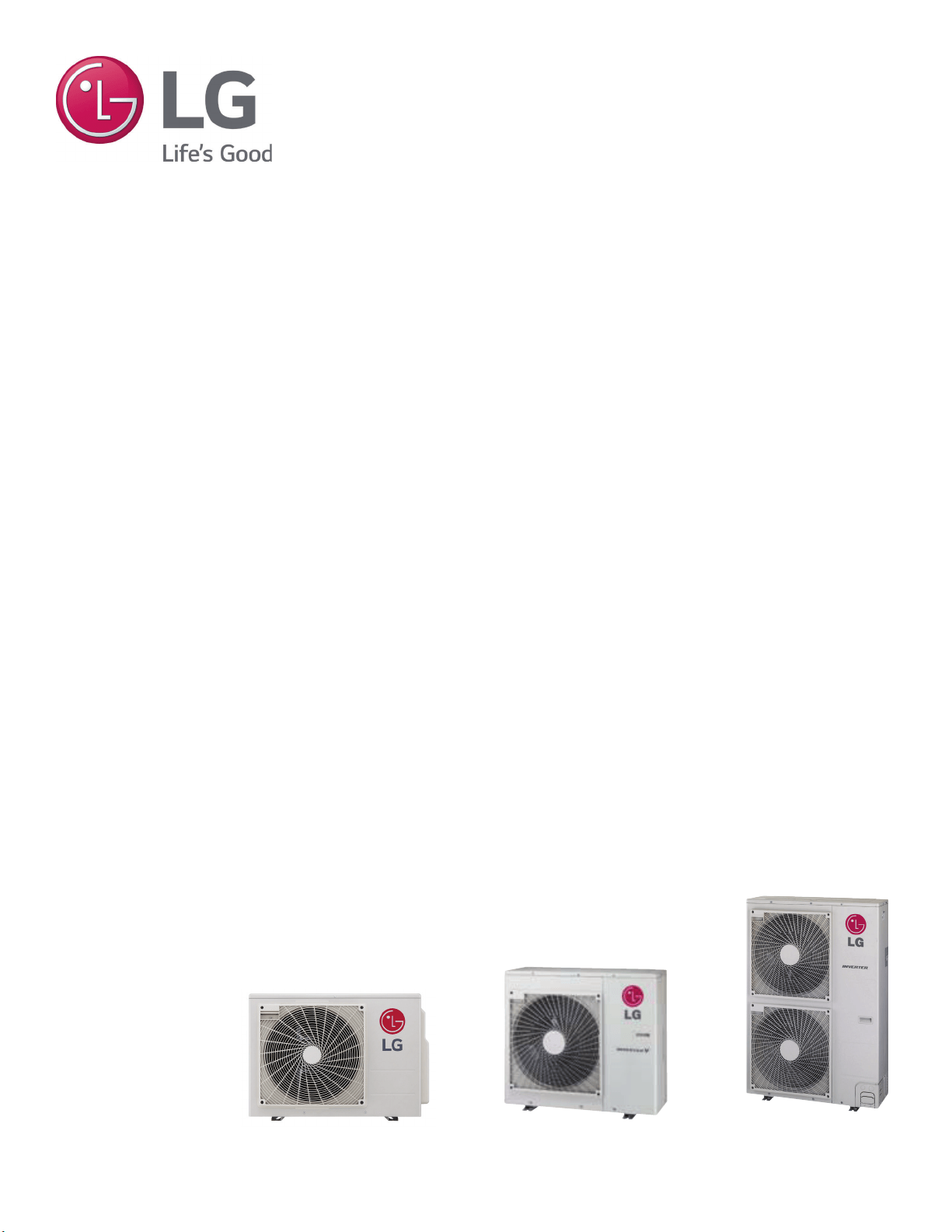
OUTDOOR UNIT
INSTALLATION MANUAL
Multi-Zone Heat Pump Systems
1.5 to 5 Tons
Dual and Tri-Zone
Multi F
Quad-Zone
Multi F
Eight-Zone
Multi F MAX
For continual product development, LG Electronics U.S.A., Inc. reserves the right to change specifications without notice.
© LG Electronics U.S.A., Inc.
PROPRIETARY DATA NOTICE
For more technical materials such as submittals, catalogs, engineering,
owner’s, best practices, building ventilation guide, and service manuals,
visit www.lghvac.com.
Do not throw away, destroy, or lose this manual.
Please read carefully and store in a safe place for future reference.
Content familiarity is required for proper installation.
The instructions included in this manual must be followed to prevent product malfunction, property damage, injury, or death to the user or
other people. Incorrect operation due to ignoring any instructions will cause harm or damage. The level of seriousness is classified by the
symbols described by the summary list of safety precautions on page 4.
This document, as well as all reports, illustrations, data, information,
and other materials are the property of LG Electronics U.S.A., Inc., and are
disclosed by LG Electronics U.S.A., Inc. only in confidence.

3
Due to our policy of continuous product innovation, some specifications may change without notification.
©LG Electronics U.S.A., Inc., Englewood Cliffs, NJ. All rights reserved. “LG” is a registered trademark of LG Corp.
MULTI
F
MAX
MULTI
F
WITH
TABLE OF CONTENTS
Safety Instructions ......................................................................................................................................................................................................4-7
Nomenclature ..................................................................................................................................................................................................................8
General Data ..............................................................................................................................................................................................................9-19
Installation ................................................................................................................................................................................................................20-33
Transporting / Lifting ...................................................................................................................................................................................................20
Placement Considerations .....................................................................................................................................................................................21-30
Mounting / Anchoring .............................................................................................................................................................................................31-33
General Refrigerant Piping System Information ..................................................................................................................................................34-48
LATS ......................................................................................................................................................................................................................34-35
Refrigerant Safety/Device ......................................................................................................................................................................................36-37
Selecting Copper Piping .............................................................................................................................................................................................38
Copper Expansion/Contraction ..............................................................................................................................................................................39-41
Piping Handling ..........................................................................................................................................................................................................42
Refrigerant System Engineering ............................................................................................................................................................................43-46
Flaring and Brazing Procedures ............................................................................................................................................................................47-48
Refrigerant Piping System Installation .................................................................................................................................................................49-57
Installing Multi F Systems ......................................................................................................................................................................................49-50
Installing Multi F MAX Systems .............................................................................................................................................................................51-55
Bundling/SpecialApps .................................................................................................................................................................................................56
Condensate Drain Piping ............................................................................................................................................................................................57
Insulation ..................................................................................................................................................................................................................58-60
Electrical ...................................................................................................................................................................................................................61-76
General Information ....................................................................................................................................................................................................61
&RQQHFWLRQVDQG6SHFL¿FDWLRQV ............................................................................................................................................................................62-65
Installation .............................................................................................................................................................................................................66-76
Final Installation Procedures .................................................................................................................................................................................77-91
Triple Leak / Pressure Test ....................................................................................................................................................................................77-78
Deep Evacuation Test ............................................................................................................................................................................................78-79
Triple Evacuation Test............................................................................................................................................................................................79-80
Refrigerant Charge ................................................................................................................................................................................................81-83
Cautions for Refrigerant Leaks ..............................................................................................................................................................................84-85
Test Run .....................................................................................................................................................................................................................86
DIP Switch Settings for Optional Modes ................................................................................................................................................................87-91
Error Codes ..............................................................................................................................................................................................................92-93
LGMV Diagnostic Software .....................................................................................................................................................................................94-95
LG SIMS ....................................................................................................................................................................................................................96-97
Maintenance Recommendations ................................................................................................................................................................................98
Checklists and Worksheets ..................................................................................................................................................................................99-104
4
MULTI F / MULTI F MAX Outdoor Unit Installation Manual
Due to our policy of continuous product innovation, some specifications may change without notification.
©LG Electronics U.S.A., Inc., Englewood Cliffs, NJ. All rights reserved. “LG” is a registered trademark of LG Corp.
MULTI
F
MAX
MULTI
F
SAFETY INSTRUCTIONS
TABLE OF SYMBOLS
This symbol indicates an imminently hazardous situation which, if not avoided, will result in death or serious injury.
This symbol indicates a potentially hazardous situation which, if not avoided, could result in death or serious injury.
This symbol indicates a potentially hazardous situation which, if not avoided, may result in minor or moderate injury.
This symbol indicates situations that may result in equipment or property damage accidents only.
This symbol indicates an action must not be completed.
DANGER
CAUTION
Do not install or remove the unit by yourself (end user).
Ask the dealer or an trained technician to install the unit.
,PSURSHULQVWDOODWLRQE\WKHXVHUZLOOUHVXOWLQ¿UHH[SORVLRQHOHFWULF
shock, physical injury or death.
For replacement of an installed unit, always contact an LG
trained service provider.
7KHUHLVULVNRI¿UHHOHFWULFVKRFNH[SORVLRQDQGSK\VLFDOLQMXU\RU
death.
Wear protective gloves when handling equipment. Sharp
edges will cause personal injury.
Do not change the settings of the protection devices.
If the protection devices have been bypassed or is forced to operate
LPSURSHUO\RUSDUWVRWKHUWKDQWKRVHVSHFL¿HGE\/*DUHXVHGWKHUHLV
ULVNRI¿UHHOHFWULFVKRFNH[SORVLRQDQGSK\VLFDOLQMXU\RUGHDWK
Replace all control box and panel covers.
If cover panels are not installed securely, dust, water and animals will
HQWHUWKHRXWGRRUXQLWFDXVLQJ¿UHHOHFWULFVKRFNDQGSK\VLFDOLQMXU\RU
death.
Always check for system refrigerant leaks after the unit has
been installed or serviced.
Exposure to high concentration levels of refrigerant gas will lead to
illness or death.
Periodically check that the outdoor frame is not damaged.
There is a risk of explosion, physical injury, or death.
If the air conditioner is installed in a small space, take
measures to prevent the refrigerant concentration from
exceeding safety limits in the event of a refrigerant leak.
Consult the latest edition of ASHRAE (American Society of Heating,
Refrigerating, and Air Conditioning Engineers) Standard 15. If the
refrigerant leaks and safety limits are exceeded, it could result in person-
al injuries or death from oxygen depletion.
The branch distribution (BD) unit must be installed indoors;
do not install the BD unit in a highly humid environment.
There is risk of physical injury or death due to electric shock.
Dispose the packing materials safely.
• Packing materials, such as nails and other metal or wooden parts,
will cause puncture wounds or other injuries.
• Tear apart and throw away plastic packaging bags so that children
will not play with them and risk suffocation and death.
Install the unit considering the potential for strong winds or
earthquakes.
Improper installation will cause the unit to fall over, resulting in physical
injury or death.
Install the unit in a safe location where nobody can step, fall
onto it, or place objects on it.
Do not install the unit on a
defective stand.
It will result in an accident that causes physical injury or death.
Installation
'RQRWVWRUHRUXVHÀDPPDEOHJDVRUFRPEXVWLEOHVQHDU
the unit.
7KHUHLVULVNRI¿UHH[SORVLRQDQGSK\VLFDOLQMXU\RUGHDWK
Do not supply power to the unit until all wiring and pip-
ing are completed or reconnected and checked.
There is risk of physical injury or death due to electric shock.
DANGER
The instructions below must be followed to prevent product malfunction, property damage, injury or death to the user or other people. Incor-
rect operation due to ignoring any instructions will cause harm or damage. The level of seriousness is classified by the symbols described
below.
5
Safety Instructions
Due to our policy of continuous product innovation, some specifications may change without notification.
©LG Electronics U.S.A., Inc., Englewood Cliffs, NJ. All rights reserved. “LG” is a registered trademark of LG Corp.
MULTI
F
MAX
MULTI
F
SAFETY INSTRUCTIONS
CAUTION
Installation, continued
Be very careful when transporting the product. There is a risk of the product falling and causing physical injury.
• Use appropriate moving equipment to transport each frame; ensure the equipment is capable of supporting the weights listed.
• Some products use polypropylene bands for packaging.
Do not use polypropylene bands to lift the unit.
• Support the outdoor unit a minimum of four points to avoid slippage from rigging apparatus.
LG Electronics U.S.A.,Inc., is not responsible for any piping
calculations, refrigerant leaks, degradation of performance,
or any other potential problems or damages as a result of
interconnecting piping, their joint connections, isolation
valves, introduced debris inside the piping system, or other
problems caused by the interconnecting piping system.
Do not install the product where it is exposed directly to
ocean winds.
Sea salt in the air will cause the product to corrode. Corrosion, par-
WLFXODUO\RQWKHFRQGHQVHUDQGHYDSRUDWRU¿QVFRXOGFDXVHSURGXFW
PDOIXQFWLRQRULQHI¿FLHQWRSHUDWLRQ
When installing the outdoor unit in a low-lying area, or a lo-
cation that is not level, use a raised concrete pad or concrete
blocks to provide a solid, level foundation.
This prevents water damage and abnormal vibration.
Properly insulate all cold surfaces to prevent “sweating.”
Cold surfaces such as uninsulated piping can generate condensate that
will drip and cause water damage to walls.
Always check for system refrigerant leaks after the unit has
been installed or serviced.
Low refrigerant levels will cause product failure.
The branch distribution (BD) unit must be installed indoors;
Do not install the BD box in a highly humid environment.
There is risk of product failure and property damage.
Do not make refrigerant substitutions. Use R410A only.
If a different refrigerant is used, or air mixes with original refrigerant, the
unit will malfunction and be damaged.
'RQRWVWRUHRUXVHÀDPPDEOHJDVFRPEXVWLEOHVQHDU
the unit.
There is a risk of product failure.
Do not use the product for mission critical or special pur-
pose applications such as preserving foods, works of art, or
other precision air conditioning applications. The equipment
is designed to provide comfort cooling and heating.
There is risk of property damage.
Keep the unit upright during installation to avoid vibration or
water leakage.
When connecting refrigerant tubing, remember to allow for
pipe expansion.
Improper piping will cause refrigerant leaks and system malfunction.
Do not install the outdoor unit or BD unit in a noise-sen-
sitive area.
Take appropriate actions at the end of HVAC equipment life
to recover, recycle, reclaim or destroy R410A refrigerant
according to applicable U.S. Environmental Protection
Agency (EPA) rules.
Periodically check that the outdoor frame is not damaged.
There is a risk of equipment damage.
Install the unit in a safe location where nobody can step on
or fall onto it.
Do not install the unit on a defective stand.
There is a risk of unit and property damage.
Install the drain hose to ensure adequate drainage.
There is a risk of water leakage and property damage.
Properly insulate all cold surfaces to prevent “sweating.”
Cold surfaces such as uninsulated piping can generate condensate that could drip, causing a slippery surface that creates a risk of slipping, falling,
and personal injury.
6
MULTI F / MULTI F MAX Outdoor Unit Installation Manual
Due to our policy of continuous product innovation, some specifications may change without notification.
©LG Electronics U.S.A., Inc., Englewood Cliffs, NJ. All rights reserved. “LG” is a registered trademark of LG Corp.
MULTI
F
MAX
MULTI
F
SAFETY INSTRUCTIONS
Do not supply power to the unit until all electrical wiring,
controls wiring, piping, installation, and refrigerant system
evacuation are completed.
System will malfunction.
The information contained in this manual is intended for use
E\DQLQGXVWU\TXDOL¿HGH[SHULHQFHGFHUWL¿HGHOHFWULFLDQ
familiar with the U.S. National Electric Code (NEC) who is
equipped with the proper tools and test instruments.
Failure to carefully read and follow all instructions in this manual can
result in equipment malfunction and / or property damage.
The information contained in this manual is intended for use
E\DQLQGXVWU\TXDOL¿HGH[SHULHQFHGFHUWL¿HGHOHFWULFLDQ
familiar with the U.S. National Electric Code (NEC) who is
equipped with the proper tools and test instruments.
Failure to carefully read and follow all instructions in this manual can
result in personal injury or death.
All electric work must be performed by a licensed electrician
and conform to local building codes or, in the absence of
local codes, with the National Electrical Code, and the
instructions given in this manual.
If the power source capacity is inadequate or the electric work is not
SHUIRUPHGSURSHUO\LWZLOOUHVXOWLQ¿UHHOHFWULFVKRFNSK\VLFDOLQMXU\RU
death.
Refer to local, state, and federal codes, and use power wires
RIVXႈFLHQWFXUUHQWFDSDFLW\DQGUDWLQJ
:LUHVWKDWDUHWRRVPDOOZLOOJHQHUDWHKHDWDQGFDXVHD¿UH
6HFXUHDOO¿HOGZLULQJFRQQHFWLRQVZLWKDSSURSULDWHZLUH
strain relief.
Improperly securing wires will create undue stress on equipment power
OXJV,QDGHTXDWHFRQQHFWLRQVZLOOJHQHUDWHKHDWFDXVHD¿UHDQGSK\VL-
cal injury or death.
Ensure the system is connected to a dedicated power source
that provides adequate power.
If the power source capacity is inadequate or the electric work is not
SHUIRUPHGSURSHUO\LWZLOOUHVXOWLQ¿UHHOHFWULFVKRFNSK\VLFDOLQMXU\RU
death.
Properly tighten all power connections.
/RRVHZLULQJZLOORYHUKHDWDWFRQQHFWLRQSRLQWVFDXVLQJD¿UHSK\VLFDO
injury or death.
Do not change the settings of the protection devices.
If the protection devices have been bypassed or are forced to operate
LPSURSHUO\RUSDUWVRWKHUWKDQWKRVHVSHFL¿HGE\/*DUHXVHGWKHUHLV
ULVNRI¿UHHOHFWULFVKRFNH[SORVLRQDQGSK\VLFDOLQMXU\RUGHDWK
Wiring
DANGER
High voltage electricity is required to operate this system.
Adhere to the NEC code and these instructions when wiring.
Improper connections and inadequate grounding can cause accidental
injury or death.
Always ground the unit following local, state, and NEC codes.
7KHUHLVULVNRI¿UHHOHFWULFVKRFNDQGSK\VLFDOLQMXU\RUGHDWK
7XUQWKHSRZHURႇDWWKHQHDUHVWGLVFRQQHFWEHIRUHVHUYLFLQJ
the equipment.
Electrical shock can cause physical injury or death.
Properly size all circuit breakers or fuses.
7KHUHLVULVNRI¿UHHOHFWULFVKRFNH[SORVLRQSK\VLFDOLQMXU\RUGHDWK
Do not share the electrical circuit with other appliances.
7KHUHLVULVNRI¿UHHOHFWULFVKRFNDQGSK\VLFDOLQMXU\RUGHDWKGXHWR
heat generation.
Do not use damaged or loose power wiring. Do not
randomly modify or extend the outdoor unit’s power wiring.
Ensure that the power wiring will not be pulled nor weight be
placed on the power wiring during operation.
7KHUHLVULVNRI¿UHHOHFWULFVKRFNDQGSK\VLFDOLQMXU\RUGHDWK
7
Safety Instructions
Due to our policy of continuous product innovation, some specifications may change without notification.
©LG Electronics U.S.A., Inc., Englewood Cliffs, NJ. All rights reserved. “LG” is a registered trademark of LG Corp.
MULTI
F
MAX
MULTI
F
Do not allow water, dirt, or animals to enter the unit.
7KHUHLVULVNRI¿UHHOHFWULFVKRFNSK\VLFDOLQMXU\RUGHDWK
Do not operate the unit with the panel(s) or protective
FRYHUVUHPRYHGNHHS¿QJHUVDQGFORWKLQJDZD\IURP
moving parts.
The rotating, hot, cold, and high-voltage parts of the unit can cause
physical injury or death.
Do not touch the refrigerant piping during or after
operation.
It can cause burns or frostbite.
Do not open the inlet during operation.
There is risk of electric shock, physical injury or death.
Operation
DANGER
'RQRWSURYLGHSRZHUWRRURSHUDWHWKHXQLWLILWLVÀRRGHG
or submerged.
7KHUHLVULVNRI¿UHHOHFWULFVKRFNSK\VLFDOLQMXU\RUGHDWK
Use a dedicated breaker for this product.
7KHUHLVULVNRI¿UHHOHFWULFVKRFNSK\VLFDOLQMXU\RUGHDWK
Do not operate the disconnect switch with wet hands.
7KHUHLVULVNRI¿UHHOHFWULFVKRFNSK\VLFDOLQMXU\RUGHDWK
Periodically verify the equipment mounts have not
deteriorated.
If the base collapses, the unit could fall and cause physical injury or
death.
Use inert (nitrogen) gas when performing leak tests or air
purges.
'RQRWXVHFRPSUHVVHGDLUR[\JHQRUÀDPPD-
ble gases.
8VLQJWKHVHVXEVWDQFHVZLOOFDXVH¿UHH[SORVLRQDQGSK\VLFDOLQMXU\RU
death.
If refrigerant leaks out, ventilate the area before operating the
unit.
If the unit is mounted in an enclosed, low-lying, or poorly ventilated area,
DQGWKHV\VWHPGHYHORSVDUHIULJHUDQWOHDNLWZLOOFDXVHD¿UHHOHFWULF
shock, explosion, physical injury or death.
To avoid physical injury, use caution when cleaning or servicing the air conditioner.
There is risk of electric shock, physical injury or death.
CAUTION
&OHDQXSWKHVLWHDIWHUVHUYLFLQJLV¿QLVKHGDQGFKHFNWKDW
no metal scraps, screws, or bits of wiring have been left
inside or surrounding the unit.
Do not use the product for mission critical or special pur-
pose applications such as preserving foods, works of art, or
other precision air conditioning applications. The equipment
is designed to provide comfort cooling and heating.
2LOVWHDPVXOIXULFVPRNHHWFFDQVLJQL¿FDQWO\UHGXFHWKHSHUIRUPDQFH
of the unit, or damage its parts.
Do not block the inlet or outlet.
Unit will malfunction.
Do not allow water, dirt, or animals to enter the unit.
There is risk of unit failure.
Do not open the inlet during operation.
There is risk of unit failure.
Do not operate the unit when the panel(s) or protective
cover(s) are removed.
Non-secured covers can result in product malfunction due to dust or
water in the service panel.
Periodically verify the equipment mounts have not
deteriorated.
If the base collapses, the unit could fall and cause property damage or
product failure.
Use a only soft cloth to clean the air conditioner. Do not
use wax, thinner, or strong detergents.
Strong cleaning products will damage the surface of the air conditioner,
or will cause its appearance to deteriorate.
SAFETY INSTRUCTIONS

MULTI
F
MAX
MULTI
F
8
MULTI F / MULTI F MAX Outdoor Unit Installation Manual
Due to our policy of continuous product innovation, some specifications may change without notification.
©LG Electronics U.S.A., Inc., Englewood Cliffs, NJ. All rights reserved. “LG” is a registered trademark of LG Corp.
NOMENCLATURE
Multi-Zone Systems — Indoor Units and Outdoor Units
M
DN 12 6 HV
Generation
Features:
H = Heat Pump
V = Inverter
T = High Wall-Mounted Indoor Unit
P = Art Cool Gallery Indoor Unit
Nominal Capacity
(Nominal cooling capacity in Btu/h):
Component:
AN: Art Cool™ Wall-Mounted Indoor Unit
N: Standard Wall-Mounted Indoor Unit
CN: Four-Way Ceiling-Cassette Indoor Unit
DN: Ceiling-Concealed Duct (Low Static) Indoor Unit
HN: Ceiling-Concealed Duct (High Static) Indoor Unit
QN: Low-Wall Console Indoor Unit
VN: Vertical-Horizontal Air Handling Indoor Unit
U: Outdoor Unit
L = LG
07 = 7,000
09 = 9,000
12 = 12,000
15 = 15,000
18 = 18,000
24 = 24,000
30 = 30,000
36 = 36,000
42 = 42,000
48 = 48,000
54 = 54,000
60 = 60,000
L
Type: M = Multi-Zone
• Voltage for all equipment is 208-230V, 60 Hz, 1-phase.
• All indoor units are compatible with wired controllers.
• All outdoor units are LGAP control network compatible with PI-485 V-net Control Integration Board (PMNFP14A1, sold separately).
• Compatible single zone IDU nomenclature is listed in the Single Zone Wall-Mounted IDU Engineering Manual.
Branch Distribution Units
M
BD 36
BD: Branch Distribution Unit
P = Part (Accessory)
P
Type: M = Multi-Zone
Family
Number of Port Connections
(Maximum Number of Connectible Indoor Units): 2, 3, 4
Generation: 0, 1
02
MULTI
F
MAX
MULTI
F
9
Product Data
Due to our policy of continuous product innovation, some specifications may change without notification.
©LG Electronics U.S.A., Inc., Englewood Cliffs, NJ. All rights reserved. “LG” is a registered trademark of LG Corp.
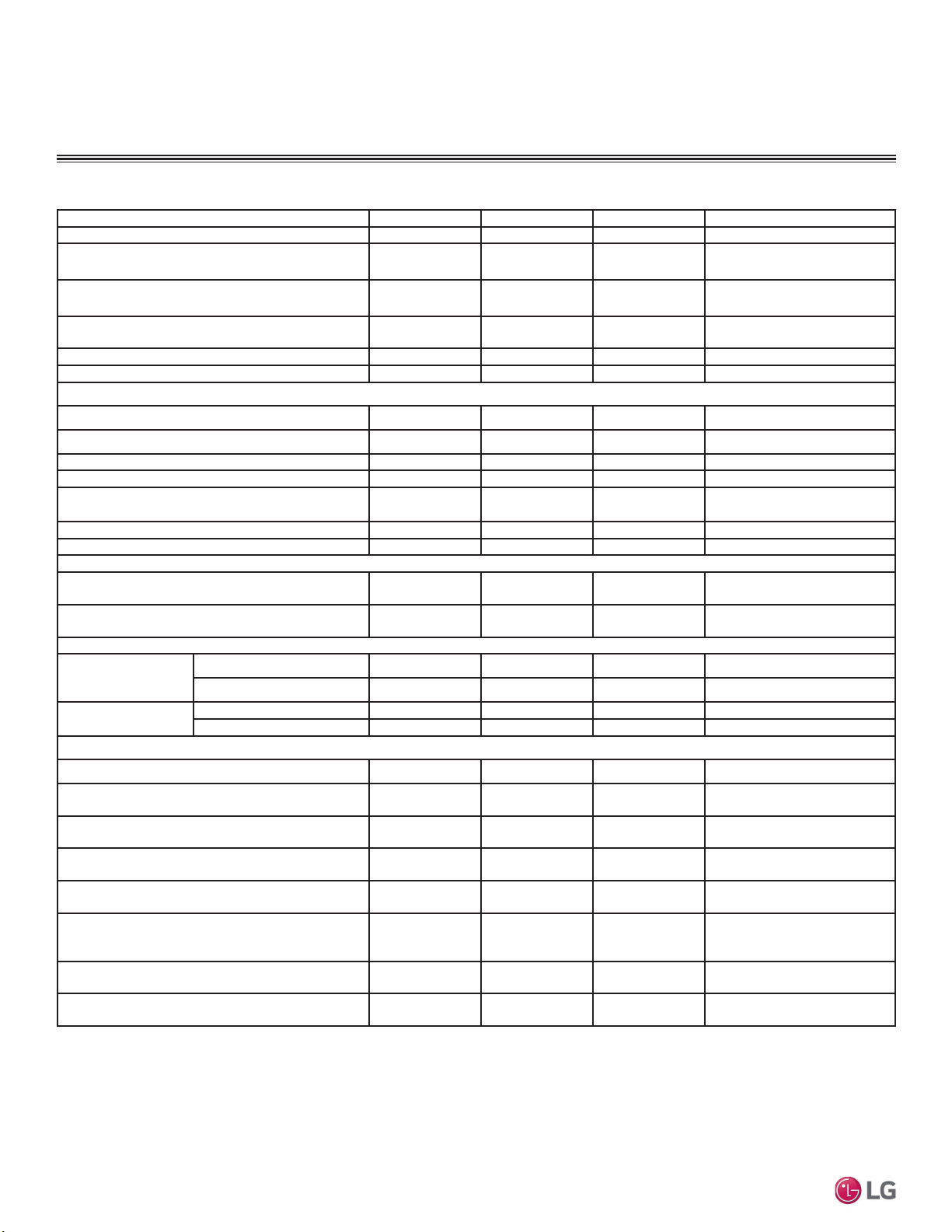
GENERAL DATA
Table 1: 0XOWL)2XWGRRU8QLW6SHFL¿FDWLRQV
1
Rated capacity applied with non-ducted indoor units, and is rated 0 ft. above sea level
with 25 ft. of refrigerant line per indoor unit and a 0 ft. level difference between outdoor and
indoor units. All capacities are net with a combination ratio between 95 – 105%.
Rated cooling capacity obtained with air entering the indoor unit at 80ºF dry bulb (DB) and
67ºF wet bulb (WB) and outdoor ambient conditions of 95ºF dry bulb (DB) and 75ºF wet
bulb (WB).
Rated heating capacity obtained with air entering the indoor unit at 70ºF dry bulb (DB) and
60ºF wet bulb (WB) and outdoor ambient conditions of 47ºF dry bulb (DB) and 43ºF wet
bulb (WB).
2
At least two indoor units must be connected. For allocated capacity information, see
the combination tables in the "Multi F / Multi F MAX Combination Data Manual" on www.
lghvac.com. For performance data, see "Multi F / Multi F MAX Performance Data Manual"
on www.lghvac.com.
3
Sound pressure levels are tested in an anechoic chamber under ISO Standard 3745 and
are the same in both cooling and heating mode. These values can increase due to ambient
conditions during operation.
4
3RZHUZLULQJWRWKHRXWGRRUXQLWLV¿HOGVXSSOLHGVROLGRUVWUDQGHGDQGPXVWFRPSO\ZLWK
the applicable local and national codes. For detailed information, please refer to electrical
characteristics on page 11.
5
Power wiring / communication cable to be minimum 14 AWG, 4-conductor from the
outdoor unit to the indoor unit, stranded, shielded or unshielded (if shielded, it must be
grounded to the chassis of the outdoor unit only), and must comply with applicable local
and national codes. For detailed electrical information, please refer to electric characteris-
tics on page 11.
6
Piping lengths are equivalent.
7
,QVWDOODWLRQRIDQRSWLRQDO/RZ$PELHQW:LQG%DIÀH.LWZLOODOORZRSHUDWLRQGRZQWR)LQ
cooling mode.
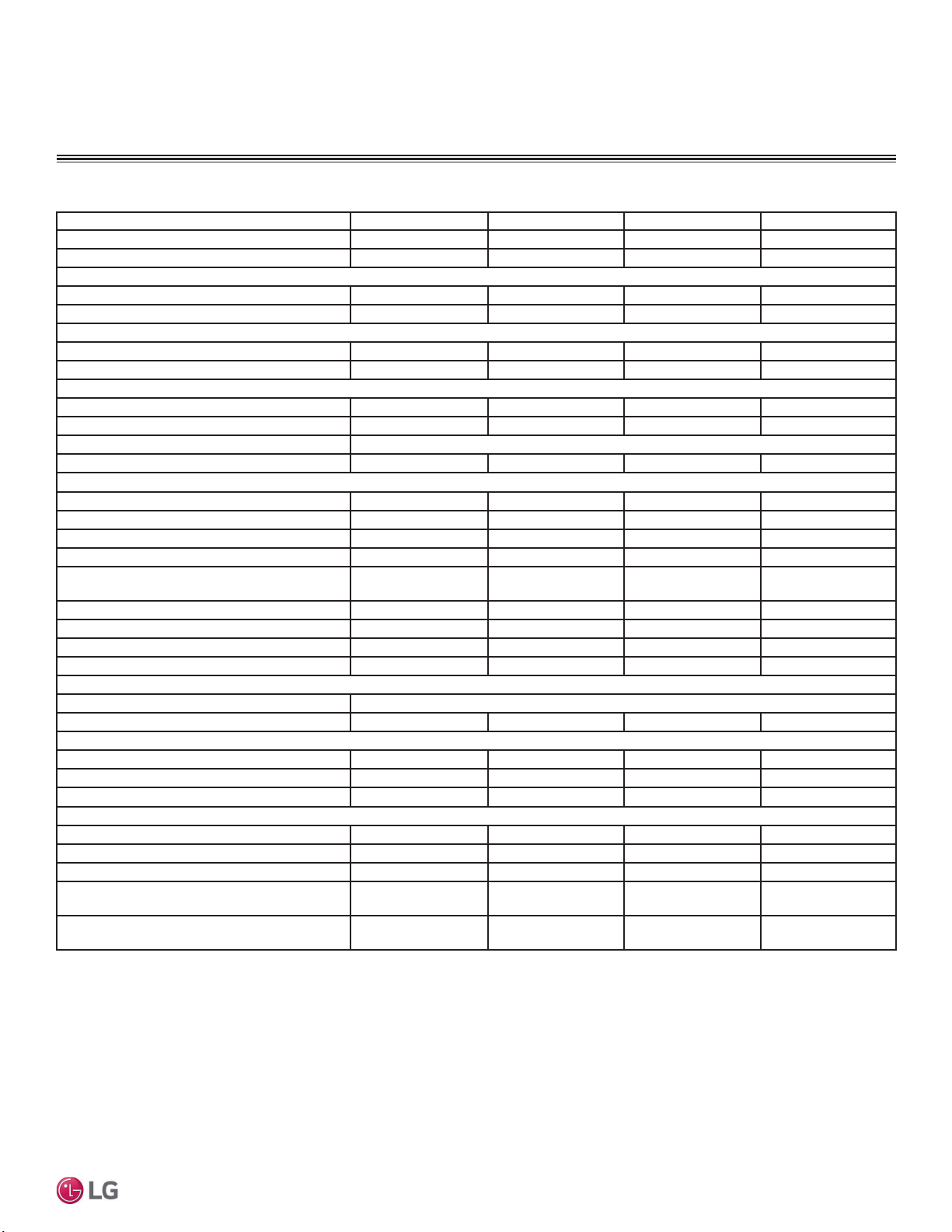
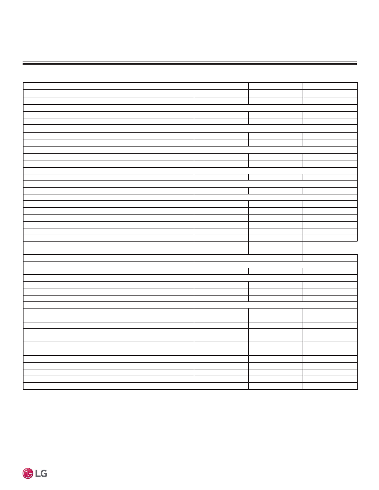
0XOWL)2XWGRRU8QLW6SHFL¿FDWLRQV
Model Number LMU180HV LMU18CHV LMU240HV LMU24CHV
Cooling Capacity (Btu/h)
1
(Min.~Rated~ Max.) 8,400~18,000~21,600 8,400~17,000~19,000 8,400~23,600~25,000 8,400~20,000~25,000
Heating Capacity (Btu/h)
1
(Min.~Rated~ Max.) 10,080~22,000~25,000 10,248~22,000~24,000 10,080~24,600~29,000 9,240~24,000~28,800
Operating Range
Cooling (°F DB) 14
7
to 118 14
7
to 118 14
7
to 118 14
7
to 118
Heating (°F WB) -4 to +64 -4 to +64 -4 to +64 -4 to +64
Compressor
Inverter Quantity Twin Rotary x 1 Twin Rotary x 1 Twin Rotary x 1 Twin Rotary x 1
Oil/Type FVC68D FVC68D FVC68D FVC68D
Fan (Side Discharge)
Type Propeller Propeller Propeller Propeller
Motor Output (W) x Qty. 85.4 x 1 85.4 x 1 85.4 x 1 85.4 x 1
Motor / Drive Brushless Digitally Controlled / Direct
Maximum Air Volume (CFM) 1,766 1,766 1,766 1,766
Unit Data
Refrigerant Type R410A R410A R410A R410A
Refrigerant Control/Location EEV / Outdoor Unit EEV / Outdoor Unit EEV / Outdoor Unit EEV / Outdoor Unit
Min. Number Indoor Units / System
2
2222
Max. Number Indoor Units / System
2
2233
Maximum Allowable Total Indoor Unit
Connected Capacity (Btu/h)
24,000 24,000 33,000 33,000
Sound Pressure (Cooling / Heating) dB(A)
3
49 / 54 49 / 52 50 / 54 49 / 52
Net Unit Weight (lbs.) 101 100 101.4 100
Shipping Weight (lbs.) 109.8 108 110.2 108
Power Wiring / Comm. Cable (No. x AWG)
4,5
4C x 14 4C x 14 4C x 14 4C x 14
Heat Exchanger
Material and Fin Coating Copper Tube/Aluminum Fin and GoldFin™/Hydrophilic
Rows / Columns/Fins per inch x Qty. (2 x 28 x 14) x 1 (2 x 28 x 14) x 1 (2 x 28 x 14) x 1 (2 x 28 x 14) x 1
Piping
Liquid Line Connection (in., OD) x Qty. 1/4 x 2 1/4 x 2 1/4 x 3 1/4 x 3
Vapor Line Connection (in., OD) x Qty. 3/8 x 2 3/8 x 2 3/8 x 3 3/8 x 3
Factory Charge lbs. of R410A 3.97 3.96 3.97 3.96
Piping Lengths
Maximum Total Piping (ft.)
6
164.0 164.0 230.0 246.1
Max. Outdoor Unit to Indoor Unit Piping (ft) 82.0 82.0 82.0 82.0
Piping Length (No Additional Refrigerant [ft]) 98.4 49.2 98.4 73.8
Max. Elevation between Outdoor Unit and
Indoor Unit (ft.)
49.2 49.2 49.2 49.2
Max. Elevation between Indoor Unit and
Indoor Unit (ft.)
24.6 24.6 24.6 24.6
MULTI
F
MAX
MULTI
F
10
MULTI F / MULTI F MAX Outdoor Unit Installation Manual
Due to our policy of continuous product innovation, some specifications may change without notification.
©LG Electronics U.S.A., Inc., Englewood Cliffs, NJ. All rights reserved. “LG” is a registered trademark of LG Corp.
GENERAL DATA
0XOWL)2XWGRRU8QLW6SHFL¿FDWLRQV
1
Rated capacity applied with non-ducted indoor units, and is rated 0 ft. above sea level
with 25 ft. of refrigerant line per indoor unit and a 0 ft. level difference between outdoor and
indoor units. All capacities are net with a combination ratio between 95 – 105%.
Rated cooling capacity obtained with air entering the indoor unit at 80ºF dry bulb (DB) and
67ºF wet bulb (WB) and outdoor ambient conditions of 95ºF dry bulb (DB) and 75ºF wet
bulb (WB).
Rated heating capacity obtained with air entering the indoor unit at 70ºF dry bulb (DB) and
60ºF wet bulb (WB) and outdoor ambient conditions of 47ºF dry bulb (DB) and 43ºF wet
bulb (WB).
2
At least two indoor units must be connected. For allocated capacity information, see
the combination tables in the "Multi F / Multi F MAX Combination Data Manual" on www.
lghvac.com. For performance data, see "Multi F / Multi F MAX Performance Data Manual"
on www.lghvac.com.
3
Sound pressure levels are tested in an anechoic chamber under ISO Standard 3745 and
are the same in both cooling and heating mode. These values can increase due to ambient
conditions during operation.
4
3RZHUZLULQJWRWKHRXWGRRUXQLWLV¿HOGVXSSOLHGVROLGRUVWUDQGHGDQGPXVWFRPSO\ZLWK
the applicable local and national codes. For detailed information, please refer to electrical
characteristics on page 11.
5
Power wiring / communication cable to be minimum 14 AWG, 4-conductor from the
outdoor unit to the indoor unit, stranded, shielded or unshielded (if shielded, it must be
grounded to the chassis of the outdoor unit only), and must comply with applicable local
and national codes. For detailed electrical information, please refer to electric characteris-
tics on page 11.
6
Piping lengths are equivalent.
7
,QVWDOODWLRQRIDQRSWLRQDO/RZ$PELHQW:LQG%DIÀH.LWZLOODOORZRSHUDWLRQGRZQWR)LQ
cooling mode.
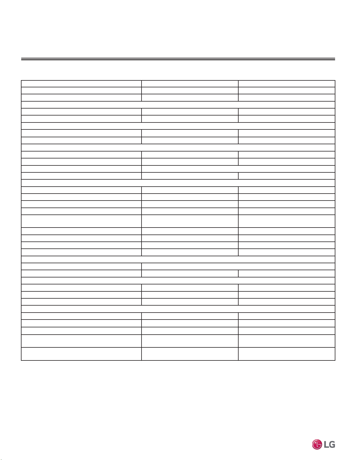
Table 2: 0XOWL)2XWGRRU8QLW6SHFL¿FDWLRQV
Model Number LMU30CHV LMU36CHV
Cooling Capacity (Btu/h)
1
(Min.~Rated~ Max.) 8,400~30,000~36,000 8,400~32,000~38,400
Heating Capacity (Btu/h)
1
(Min.~Rated~ Max.) 9,240~32,000~38,400 9,240~36,000~41,600
Operating Range
Cooling (°F DB) 14
7
to 118 14
7
to 118
Heating (°F WB) -4 to +64 -4 to +64
Compressor
Inverter Quantity Twin Rotary x 1 Twin Rotary x 1
Oil / Type FVC68D FVC68D
Fan (Side Discharge)
Type Propeller Propeller
Motor Output (W) x Qty. 124.2 x 1 124.2 x 1
Motor / Drive Brushless Digitally Controlled / Direct
Maximum Air Volume (CFM) 2,119 2,119
Unit Data
Refrigerant Type R410A R410A
Refrigerant Control/Location EEV/Outdoor Unit EEV/Outdoor Unit
Min. Number Indoor Units / System
2
22
Max. Number Indoor Units / System
2
44
Maximum Allowable Total Indoor Unit Connected
Capacity (Btu/h)
40,000 48,000
Sound Pressure (Cooling / Heating) dB(A)
3
52 / 55 52 / 55
Net Unit Weight (lbs.) 137 137
Shipping Weight (lbs.) 148 148
Power Wiring / Communications Cable (No. x AWG)
4,5
4C x 14 4C x 14
Heat Exchanger
Material and Fin Coating Copper Tube/Aluminum Fin and GoldFin™/Hydrophilic
Rows/Columns / Fins per inch x Qty. (2 x 38 x 14) x 1 (2 x 38 x 14) x 1
Piping
Liquid Line Connection (in., OD) x Qty. 1/4 x 4 1/4 x 4
Vapor Line Connection (in., OD) x Qty. 3/8 x 4 3/8 x 4
Factory Charge lbs. of R410A 6.18 6.18
Piping Lengths
Maximum Total Piping (ft.)
6
246.1 246.1
Maximum Outdoor Unit to Indoor Unit Piping (ft.) 82.0 82.0
Piping Length (No Additional Refrigerant [ft]) 98.4 98.4
Maximum Elevation between Outdoor Unit and
Indoor Unit (ft.)
49.2 49.2
Maximum Elevation between Indoor Unit and
Indoor Unit (ft.)
24.6 24.6

MULTI
F
MAX
MULTI
F
11
Product Data
Due to our policy of continuous product innovation, some specifications may change without notification.
©LG Electronics U.S.A., Inc., Englewood Cliffs, NJ. All rights reserved. “LG” is a registered trademark of LG Corp.
Table 3: Multi F Outdoor Unit Electrical Data.
GENERAL DATA
Multi F Outdoor Unit Electrical Data
Nominal
Tons
Unit Model No. Hertz Voltage
Voltage
Range
(Min. to Max.)
MCA MOP
Compressor
Quantity
Compressor
Motor RLA
Outdoor Fan Motor
Indoor
Fan
Motor
kW FLA FLA
1.5 LMU180HV
60 208 - 230 187 - 253
15.8 20 1 12.0 0.085 0.40 0.40
1.5 LMU18CHV 13.3 20 1 8.9 0.09 0.59 1.60
2 LMU240HV 16.0 20 1 12.0 0.085 0.40 0.60
2 LMU24CHV 14.3 20 1 9.4 0.09 0.59 2.00
2.5 LMU30CHV 16.6 25 1 10.8 0.12 0.73 2.40
3 LMU36CHV 17.9 25 1 11.2 0.12 0.73 3.20
Voltage tolerance is ±10%.
Maximum allowable voltage unbalance
is 2%.
RLA = Rated Load Amps.
MCA = Minimum Circuit Ampacity.
Maximum Overcurrent Protection (MOP) is calculated as follows:
(Largest motor FLA x 2.25) + (Sum of other motor FLA) rounded
down to the nearest standard fuse size.
Indoor Fan Motor (FLA) is based on the maximum combination of
indoor units.
The max combination for each outdoor unit is:
- 18,000 ODU (LMU180HV / LMU18CHV): 12,000 IDU x 2
- 24,000 ODU (LMU240HV / LMU24CHV): 12,000 IDU x 2 + 9,000
IDU x 1
- 30,000 ODU (LMU30CHV): 12,000 IDU x 3
- 36,000 ODU (LMU36CHV): 12,000 IDU x 4
MULTI
F
MAX
MULTI
F
12
MULTI F / MULTI F MAX Outdoor Unit Installation Manual
Due to our policy of continuous product innovation, some specifications may change without notification.
©LG Electronics U.S.A., Inc., Englewood Cliffs, NJ. All rights reserved. “LG” is a registered trademark of LG Corp.
GENERAL DATA
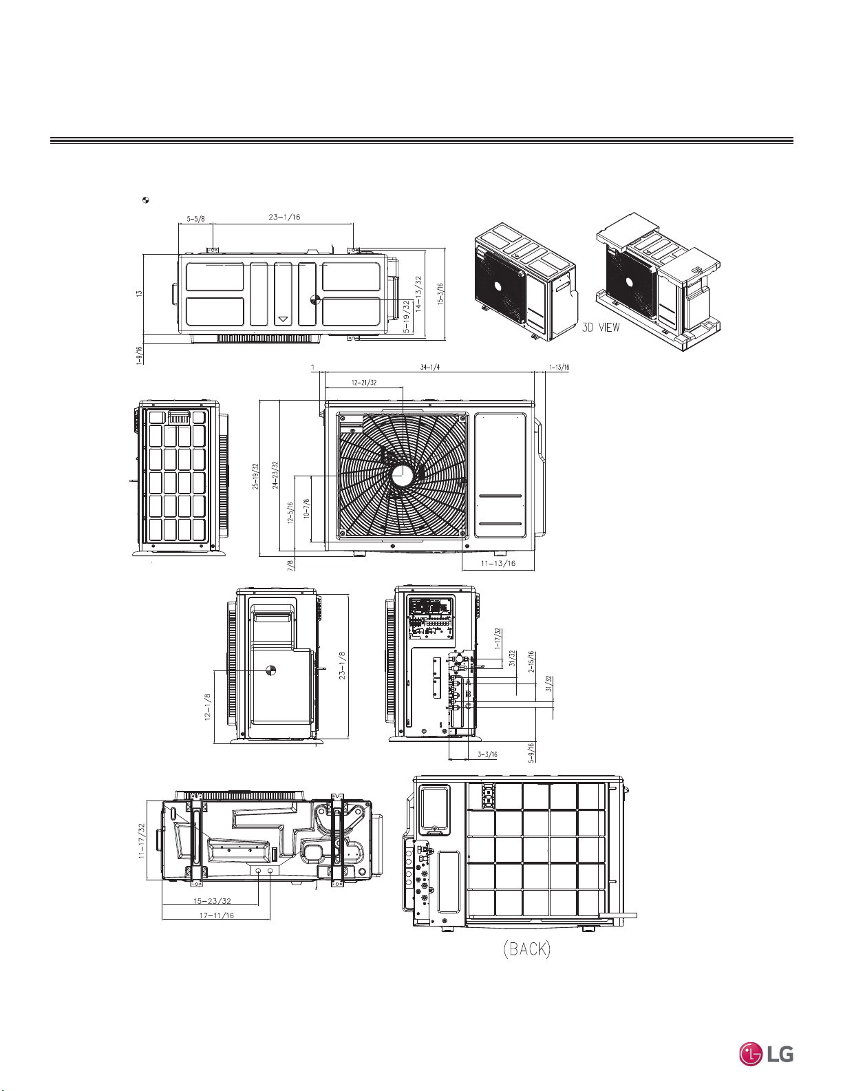
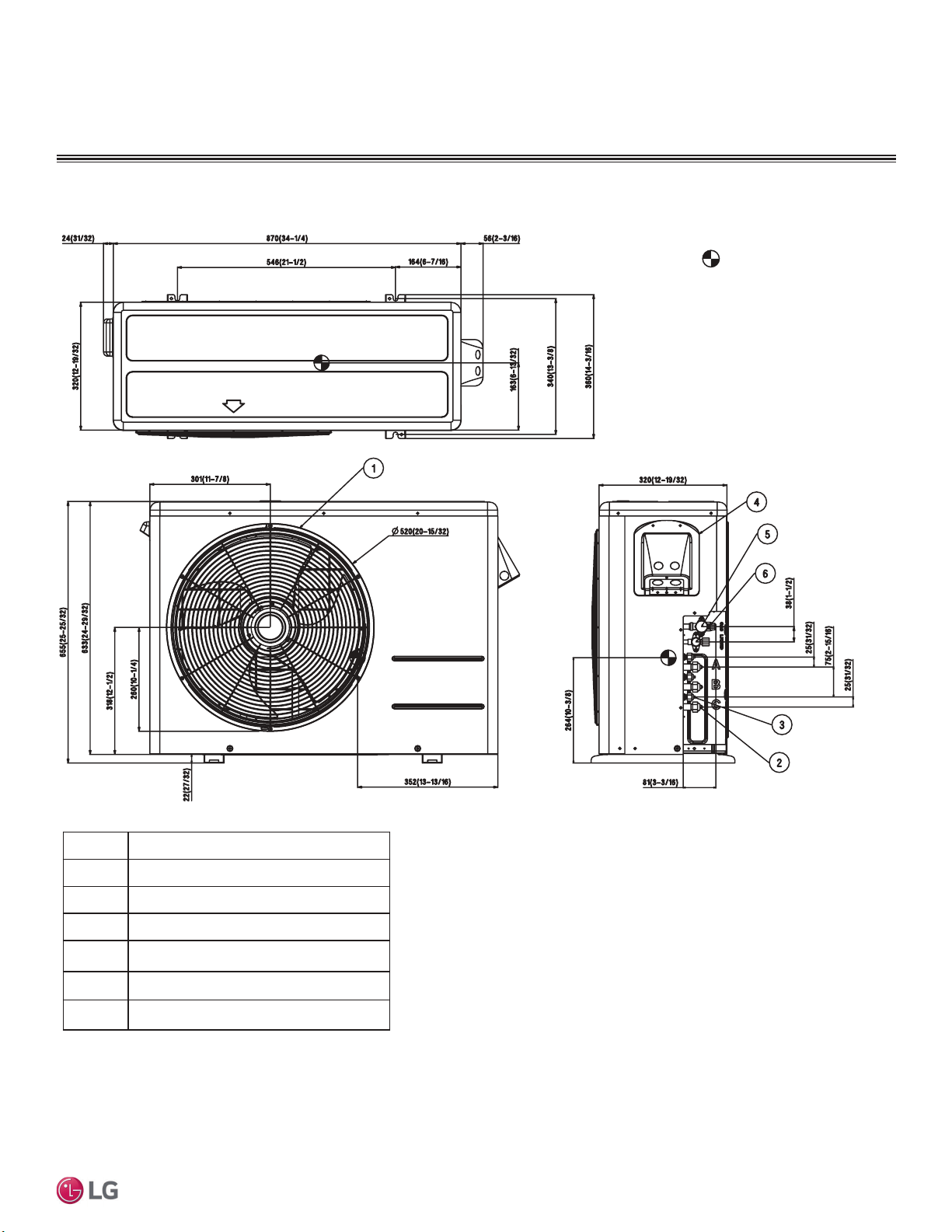
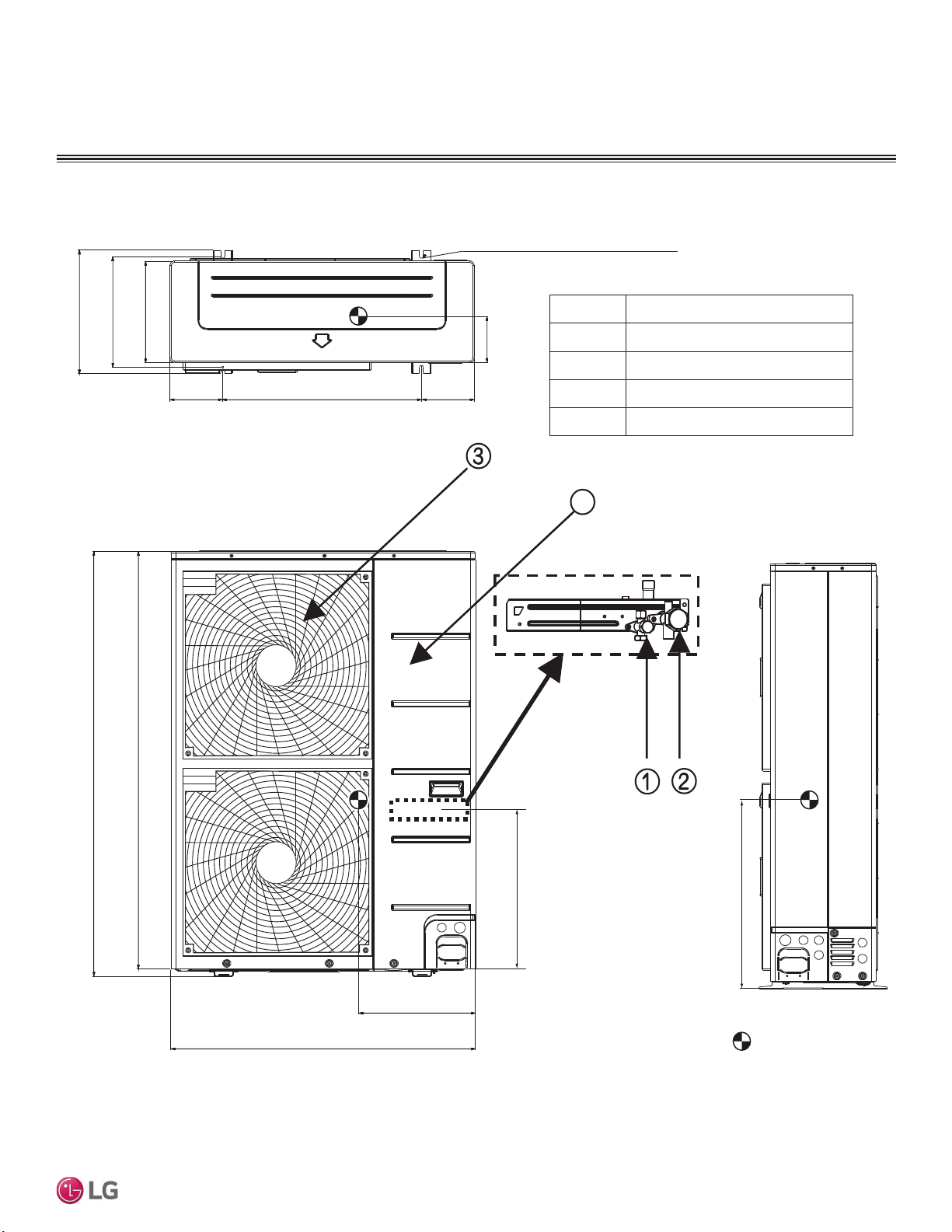
0XOWL)2XWGRRU8QLW'LPHQVLRQV
Figure 1: LMU180HV and LMU240HV Multi F Outdoor Unit External Dimensions.
Unit: Inch
Gravity point
1. Unit must be installed in compliance with the installation manual.
2. Unit must be grounded in accordance with the local or state regulations and applicable national codes.
3.
All field-supplied electrical components and materials must
comply with the local, state, and national codes.
4. Electrical characteristics must be considered for electrical work and design. The capacity of power cable and circuit
breaker for the outdoor unit must follow local, state, national, and manufacturer requirements.
Notes:
5. For LMU180HV Unit, ports A and B are available.
6. For LMU240HV Unit, ports A, B, and C are available.
MULTI
F
MAX
MULTI
F
13
Product Data
Due to our policy of continuous product innovation, some specifications may change without notification.
©LG Electronics U.S.A., Inc., Englewood Cliffs, NJ. All rights reserved. “LG” is a registered trademark of LG Corp.
GENERAL DATA
0XOWL)2XWGRRU8QLW'LPHQVLRQV
Figure 2: LMU18CHV and LMU24CHV Multi F Outdoor Unit External Dimensions.
1. Unit must be installed in compliance with the installation manual.
2. Unit must be grounded in accordance with the local or state
regulations and applicable national codes.
3. All field-supplied electrical components and materials must comply
with the local, state, and national codes.
4. Electrical characteristics must be considered for electrical
work and design. The capacity of power cable and circuit
breaker for the outdoor unit must follow local, state, national,
and manufacturer requirements.
.
Notes:
Vapor pipe connection
Part Name
Air discharge grille
Liquid pipe connection
Power & transmission connection
No.
2
4
Main service valve (Vapor)
Main service valve (Liquid)
5
6
3
1
[Unit : mm(inch)]
Gravity point
5. For LMU18CHV Unit, ports A and B are available.
6. For LMU24CHV Unit, ports A, B, and C are available.
MULTI
F
MAX
MULTI
F
14
MULTI F / MULTI F MAX Outdoor Unit Installation Manual
Due to our policy of continuous product innovation, some specifications may change without notification.
©LG Electronics U.S.A., Inc., Englewood Cliffs, NJ. All rights reserved. “LG” is a registered trademark of LG Corp.
GENERAL DATA
0XOWL)2XWGRRU8QLW'LPHQVLRQV
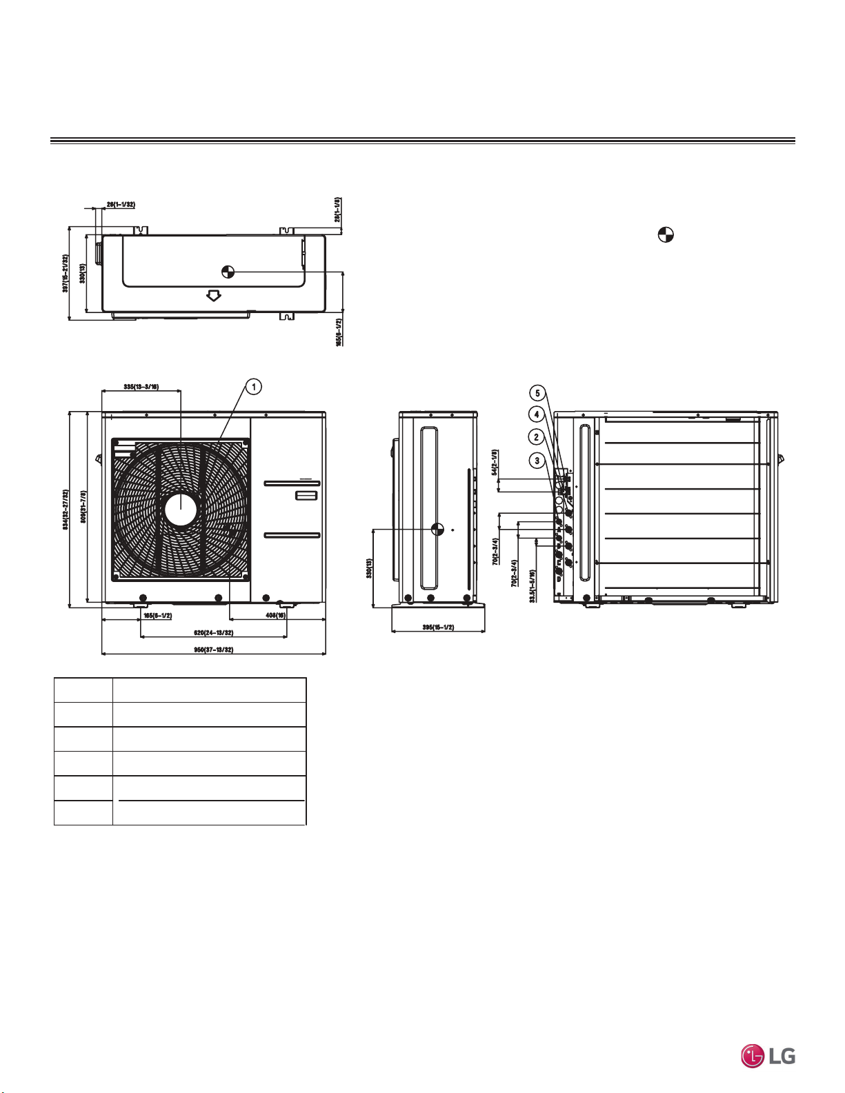
Figure 3: LMU30CHV and LMU36CHV Multi F Outdoor Unit External Dimensions.
Vapor pipe connection
Part Name
Air discharge grille
Liquid pipe connection
Main service valve (Vapor)
Main service valve (Liquid)
5
No.
2
4
3
1
[Unit : mm(inch)]
Gravity point
1. Unit must be installed in compliance with the installation manual.
2. Unit must be grounded in accordance with the local or state
regulations and applicable national codes.
3. All field-supplied electrical components and materials must comply
with local, state, and national codes.
4. Electrical characteristics must be considered for electrical
work and design. The capacity of power cable and circuit
breaker for the outdoor unit must follow local, state, national,
and manufacturer requirements.
Notes:
MULTI
F
MAX
MULTI
F
15
Product Data
Due to our policy of continuous product innovation, some specifications may change without notification.
©LG Electronics U.S.A., Inc., Englewood Cliffs, NJ. All rights reserved. “LG” is a registered trademark of LG Corp.
0XOWL)0$;2XWGRRU8QLW6SHFL¿FDWLRQV
GENERAL DATA
Table 4: Multi F MAX Outdoor Unit General Data.
Model Number LMU480HV LMU540HV LMU600HV
Cooling Capacity (Btu/h) (Minimum ~ Rated ~ Maximum)
1
14,400~48,000~58,000 14,400~52,500~63,200 15,600~60,000~68,000
Heating Capacity (Btu/h)
(Minimum ~ Rated ~ Maximum)
1
15,840~54,000~61,000 16,272~58,000~64,000 17,940~64,000~70,000
Operating Range
Cooling (°F DB) 14
7
- 118 14
7
- 118 14
7
- 118
Heating (°F WB) -4 - 64 -4 - 64 -4 - 64
Compressor
Inverter Quantity Twin Rotary x 1 Twin Rotary x 1 Twin Rotary x 1
Oil Type FVC68D FVC68D FVC68D
Fan (Side Discharge)
Type Propeller Propeller Propeller
Motor Output (W) x Qty. 124.2 x 2 124.2 x 2 124.2 x 2
Motor/Drive Brushless Digitally Controlled/Direct
Maximum Air Volume (CFM) 2,119 x 2 2,119 x 2 2,119 x 2
Unit Data
Refrigerant Type R410A R410A R410A
Refrigerant Control/Location EEV / Outdoor Unit, Branch Distribution Unit
Min. Number Indoor Units/System
2
222
Max. Number Indoor Units/System
2
888
Maximum Allowable Total Indoor Unit Connected Capacity (Btu/h) 65,000 73,000 81,000
Sound Pressure ±3 dB(A)
3
(Cooling / Heating) 54 / 56 54 / 56 56 / 58
Net Unit Weight (lbs.) 214 214 223
Shipping Weight (lbs.) 236 236 249
Power/Communications Wiring Between ODU and BD Unit
(No. X AWG)
4,5
4C X 14 4C X 14 4C x 14
Heat Exchanger
Material and Fin Coating Copper Tube / Aluminum Fin and GoldFin™/Hydrophilic
Rows/Columns/Fins per inch x Qty. (2 x 32 x 14) x 2 (2 x 32 x 14) x 2 (3 x 32 x 14) x 2
Piping
Liquid Line Connection (in., OD) x Qty. 3/8 x 1 3/8 x 1 3/8 x 1
Vapor Line Connection (in., OD) x Qty. 3/4 x 1 3/4 x 1 3/4 x 1
Factory Charge lbs. of R410A 9.7 9.7 12.3
Piping Lengths
Maximum Total System Piping (ft.)
6
475.7 475.7 475.7
Maximum Main Pipe Length (Outdoor Unit to BD Unit [ft.]) 180.4 180.4 180.4
Total Branch Piping (BD Units to all Indoor Units [ft.]) 295.3 295.3 295.3
Maximum Branch Pipe Length (Length between each
BDU and IDU [ft.])
49.2 49.2 49.2
Maximum Outdoor Unit to Indoor Unit Pipe Length (ft.) 229.6 229.6 229.6
Max. Main Piping Length (No Additional Refrigerant (ft.) 16 16 16
Max. Branch Piping Length (No Additional Refrigerant (ft.) 131 131 147.6
Maximum Elevation between Outdoor Unit and Indoor Unit (ft.) 98.4 98.4 98.4
Maximum Elevation between Indoor Unit and Indoor Unit (ft.) 49.2 49.2 49.2
Maximum Elevation between BD Unit and Indoor Unit (ft.) 32.8 32.8 32.8
Maximum Elevation between BD Unit and BD Unit (ft.) 49.2 49.2 49.2
1
Rated capacity applied with non-ducted indoor units, and is rated 0 ft. above sea level with a 0
ft. level difference between outdoor and indoor units. All capacities are net with a combination
ratio between 95 – 105%.
Rated cooling capacity obtained with air entering the indoor unit at 80ºF dry bulb (DB) and 67ºF
wet bulb (WB) and outdoor ambient conditions of 95ºF dry bulb (DB) and 75ºF wet bulb (WB).
Rated heating capacity obtained with air entering the indoor unit at 70ºF dry bulb (DB) and 60ºF
wet bulb (WB) and outdoor ambient conditions of 47ºF dry bulb (DB) and 43ºF wet bulb (WB).
2
At least one Branch Distribution Unit is required for system operation; a maximum of two can
be installed per outdoor unit with use of Y-branch accessory (PMBL5620). At least two indoor
units must be connected. For allocated capacity information, see the combination tables in
the “Multi F / Multi F MAX Combination Data Manual” on www.lghvac.com. For performance
data, see “Multi F / Multi F MAX Performance Data Manual” on www.lghvac.com.
3
Sound pressure levels are tested in an anechoic chamber under ISO Standard 3745.
These values can increase due to ambient conditions during operation.
4
3RZHUZLULQJWRWKHRXWGRRUXQLWLV¿HOGVXSSOLHGVROLGRUVWUDQGHGDQGPXVWFRPSO\ZLWK
the applicable local and national codes. For detailed information, please refer to electrical
characteristics on page 16.
5
Power wiring / communication cable to be minimum 14 AWG, 4-conductor from the
outdoor unit to the BD unit (Multi F MAX systems only), and 14 AWG, 4-conductor from
the BD unit to the indoor unit, stranded, shielded or unshielded (if shielded, it must be
grounded to the chassis of the outdoor unit only), and must comply with applicable local
and national codes. For detailed electrical information, please refer to electric characteris-
tics on page 16.
6
Piping lengths are equivalent.
7
,QVWDOODWLRQRIDQRSWLRQDO/RZ$PELHQW:LQG%DIÀH.LWZLOODOORZRSHUDWLRQGRZQWR)LQ
cooling mode.
MULTI
F
MAX
MULTI
F
16
MULTI F / MULTI F MAX Outdoor Unit Installation Manual
Due to our policy of continuous product innovation, some specifications may change without notification.
©LG Electronics U.S.A., Inc., Englewood Cliffs, NJ. All rights reserved. “LG” is a registered trademark of LG Corp.
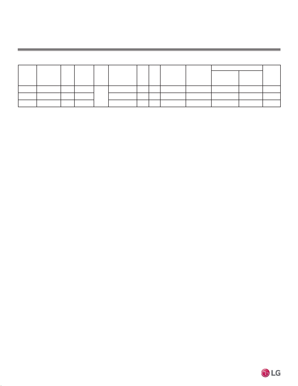
Nominal
Tons
Unit Model
No.
Hertz Voltage Phase
Voltage
Range
(Min. to Max.)
MCA MOP
Compressor
Quantity
Compressor
Motor RLA
Condenser Fan Motor(s)
Indoor
Fan
Motor
Condenser
Fan Quantity
x kW
Condenser
Fan Motor
FLA
4.0 LMU480HV 60 208 - 230
1
187 - 253 27.3 40 1 17.5 2 x 0.12 0.73 x 2 4.0
4.5 LMU540HV 60 208 - 230 187 - 253 29.4 40 1 18.5 2 x 0.12 0.73 x 2 4.8
5.0 LMU600HV 60 208 - 230 187 - 253 32.2 45 1 20.4 2 x 0.12 0.73 x 2 5.2
Voltage tolerance is ±10%.
Maximum allowable voltage unbalance is 2%.
RLA = Rated Load Amps.
MCA = Minimum Circuit Ampacity.
Maximum Overcurrent Protection (MOP) is calculated as
follows: (Largest motor FLA x 2.25) + (Sum of other motor
FLA) rounded down to the nearest standard fuse size.
Indoor Fan Motor (FLA) is based on the maximum combina-
tion of indoor units.
The max combination for each outdoor unit is:
- 48,000 ODU (LMU480HV): 12,000 IDU x 5
- 54,000 ODU (LMU540HV): 12,000 IDU x 6
- 60,000 ODU (LMU6000HV): 12,000 IDU x 6 + 9,000 IDU
x 1
Table 5: Multi F MAX Electrical Data.
GENERAL DATA
Multi F MAX Outdoor Unit Electrical Data
MULTI
F
MAX
MULTI
F
17
Product Data
Due to our policy of continuous product innovation, some specifications may change without notification.
©LG Electronics U.S.A., Inc., Englewood Cliffs, NJ. All rights reserved. “LG” is a registered trademark of LG Corp.
Supporter
4-holes for anchor bolts
No.
1
2
3
4
Part Name
Air discharge grille
Gas pipe connection
Liquid pipe connection
Power & transmission connection
4
19-9/32
21-1/20
53-3/8
54-11/32
15-3/4
6-1/2 6-1/2
24-13/32
14-3/16
13
6-5/8
14-1/20
37-13/32
Unit: inch
Center of Gravity
Figure 4: LMU480HV, LMU540HV, and LMU600HV Multi F MAX Outdoor Unit External Dimensions.
GENERAL DATA
0XOWL)0$;2XWGRRU8QLW'LPHQVLRQV
MULTI
F
MAX
MULTI
F
18
MULTI F / MULTI F MAX Outdoor Unit Installation Manual
Due to our policy of continuous product innovation, some specifications may change without notification.
©LG Electronics U.S.A., Inc., Englewood Cliffs, NJ. All rights reserved. “LG” is a registered trademark of LG Corp.
GENERAL DATA
%UDQFK'LVWULEXWLRQ8QLW6SHFL¿FDWLRQ(OHFWULFDO'DWD
Table 6: Branch Distribution Unit General Data.
1
At least one branch distribution Unit is required for system operation; a maximum of two can be installed per outdoor unit with use of Y-branch accessory (PMBL5620) To connect only
one (1) indoor unit to a branch distribution unit, the system must include another branch distribution unit with at least one (1) connected indoor unit.
2
Branch distribution Unit can accommodate from one (1) indoor unit up to four (4) indoor units depending on the ports available on the branch distribution Unit.
3
Communication / power (connection) cable must be a minimum of 14 AWG, 4-conductor from the outdoor unit to the branch distribution unit (Multi F MAX systems only), and 14 AWG,
4-conductor from the branch distribution unit to the indoor unit, stranded, shielded or unshielded (if shielded, it must be grounded to the chassis of the outdoor unit only), and must comply
with applicable local and national codes.
4
Piping lengths are equivalent.
Model Number PMBD3620 PMBD3630 PMBD3640 PMBD3641
No. of Connectible Indoor Units
1
1-2 1-3 1-4 1-4
Max. Nominal Capacity / Port (Btu/h)
2
24,000 24,000 24,000
Ports A, B, C: 24,000;
Port D: 36,000
Connected Indoor Unit Capacity 7,000 ~ 24,000 7,000 ~ 24,000 7,000 ~ 24,000
Ports A, B, C: 7,000 ~ 24,000;
Port D: 24,000 or 36,000
Max. Nominal Capacity / Branch Distribution
Unit (Btu/h)
48,000 72,000 73,000 73,000
Operation Temperature Range (°F DB) 0 ~ 150 0 ~ 150 0 ~ 150 0 ~ 150
Maximum Humidity 80% 80% 80% 80%
Unit Data
Refrigerant Type R410A R410A R410A R410A
Power Supply V, Ø, Hz 208-230, 1, 60 208-230, 1, 60 208-230, 1, 60 208-230, 1, 60
Power Input (W) 16 24 32 32
Rated Amps (A) 0.08 0.12 0.16 0.16
Dimensions W x H x D (in.)
17-3/32 x 6-13/32
x 10-23/32
17-3/32 x 6-13/32
x 10-23/32
17-3/32 x 6-13/32
x 10-23/32
17-3/32 x 6-13/32
x 10-23/32
Net Unit Weight (lbs.) 13 14.3 15.7 15.7
Shipping Weight (lbs.) 15 17 18 18
Communication / Connection (Power) Cables
3
From Outdoor Unit to Branch Distribution Unit
(Qty. x AWG)
3
4C x 14 4C x 14 4C x 14 4C x 14
From Branch Distribution Unit to Indoor Unit
(Qty. x AWG)
3
4C x 14 4C x 14 4C x 14 4C x 14
Piping Connections
Outdoor Unit to
Branch Distribution
Unit
Liquid (in., OD) Ø3/8 Ø3/8 Ø3/8 Ø3/8
Vapor (in., OD) Ø3/4 Ø3/4 Ø3/4 Ø3/4
Branch Distribution
Unit to Indoor Units
Liquid (in., OD) x Qty. Ø1/4 x 2 Ø1/4 x 3 Ø1/4 x 4 Ø1/4 x 4
Vapor (in., OD) x Qty. Ø3/8 x 2 Ø3/8 x 3 Ø3/8 x 4 Ø3/8 x 3; Ø1/2 x 1
Piping Lengths
Maximum Total System Piping (ft.)
4
475.7 475.7 475.7 475.7
Maximum Main Pipe Length (Outdoor Unit
to Branch Distribution Units [ft.])
180.4 180.4 180.4 180.4
Total Branch Piping (Branch Distribution Units
to Indoor Units [ft.])
295.3 295.3 295.3 295.3
Maximum Branch Pipe Length Between Branch
Distribution Unit and Each Indoor Unit [ft.])
49.2 49.2 49.2 49.2
Maximum Outdoor Unit to Indoor Unit
Pipe Length (ft.)
229.6 229.6 229.6 229.6
Piping Length (No Additional Refrigerant [ft.];
approx. 16 ft. of Main Piping + 131 ft. of
Branch Piping)
147.6 147.6 147.6 147.6
Maximum Elevation between Branch Distribution
Unit and Indoor Unit (ft.)
32.8 32.8 32.8 32.8
Maximum Elevation between Branch Distribution
Unit and Branch Distribution Unit (ft.)
49.2 49.2 49.2 49.2
MULTI
F
MAX
MULTI
F
19
Product Data
Due to our policy of continuous product innovation, some specifications may change without notification.
©LG Electronics U.S.A., Inc., Englewood Cliffs, NJ. All rights reserved. “LG” is a registered trademark of LG Corp.
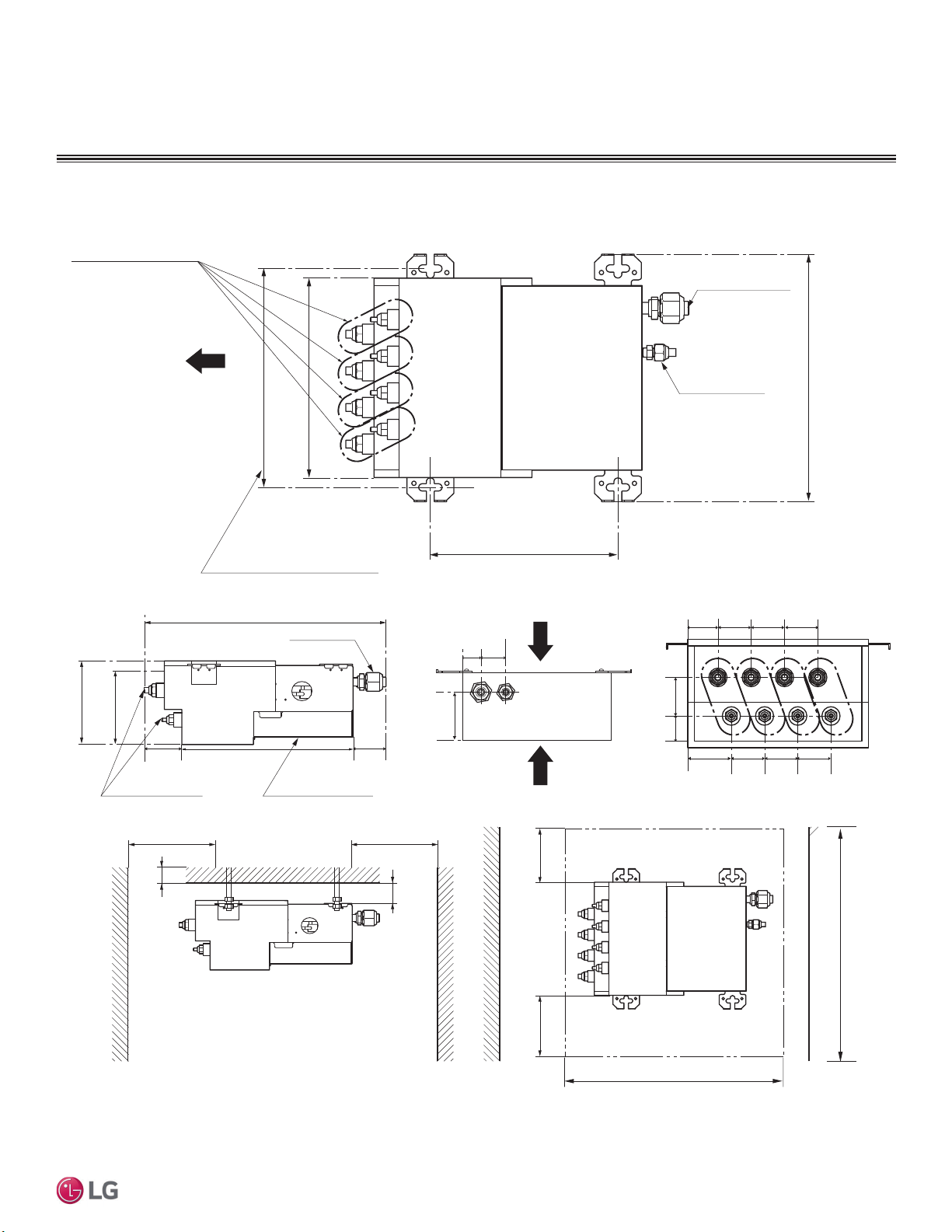
%UDQFK'LVWULEXWLRQ8QLW'LPHQVLRQV
GENERAL DATA
Figure 5: PMBD3620, PMBD3630, PMBD3640, and PMBD3641 External Dimensions.
Mininum 1-3/16
Mininum 3-15/16
Minimum 15-3/4
Branch Pipe
17
6-5/16
Cover Control
Main Pipe
Service Space
EEV Service
Controller Service
Inspection Opening
Minimum 12
Minimum 12
11-23/32
9-27/32
Ø3/4
Ø3/8
Suspension Bolt Pitch
9-21/32
13-9/32
Indoor Unit
Piping Direction
Unit: Inch
Minimum 24
Minimum 24
Bottom View
Minimum 15-3/4Mininum 15-3/4
Side View
5-29/32
2-27/32
11-13/16
2-3/8
1-3/16
1-31/32
4-3/8
A-C (and PMBD3640 D) Connections:
Liquid Pipe Ø1/4
Gas Pipe Ø3/8
PMBD3641 D Connections:
Liquid Pipe Ø1/4
Gas Pipe Ø1/2
Notes:
1. For PMBD3620 Unit, Ports A and B are Available.
2. For PMBD3630 Unit, Ports A, B, and C are Available.
3. For PMBD3640 and PMBD3641 Units, Ports A, B, C, and D are Available.
ABCD
1-1/2 1-31/32
1-23/32
1-31/32
1-31/32
1-31/32
1-31/32
1-31/32
1-31/32
2-7/32
20
MULTI F / MULTI F MAX Outdoor Unit Installation Manual
Due to our policy of continuous product innovation, some specifications may change without notification.
©LG Electronics U.S.A., Inc., Englewood Cliffs, NJ. All rights reserved. “LG” is a registered trademark of LG Corp.
MULTI
F
MAX
MULTI
F
75$163257,1*/,)7,1*
7UDQVSRUWLQJ/LIWLQJWKH2XWGRRU
Unit
• At the time of delivery, the package must be checked for any dam-
age (exterior and interior). Report any damage to the carrier claims
agent immediately.
• When lifting the unit, use lifting straps and place properly around
the unit.
• Always lift the unit using properly sized lifting straps rated to carry
the unit weight.
• (QVXUHWKHVWUDSVDUHORQJHQRXJKWRPDLQWDLQDPD[LPXPRID
angle.
Model No.
Capacity
(ton)
Shipping Weight
(lbs.)
Net Weight
(lbs.)
LMU180HV 1.5 109.8 101
LMU18CHV 1.5 108 100
LMU240HV 2 110.2 101.4
LMU24CHV 2 108 100
LMU30CHV 2.5 148 137
LMU36CHV 3 148 137
LMU480HV 4
236 214
LMU540HV 4.5
LMU600HV 5 249 223
Table 7: Multi F / Multi F MAX Shipping and Net Weights.
Be very careful when transporting the product. There is a risk of the product falling and causing physical injury.
• Use appropriate moving equipment to transport each frame; ensure the equipment is capable of supporting the weights listed above. If the
equipment is not properly secured, it will result in an accident that causes physical injury or death.
• Wear protective gloves when handling equipment. Sharp edges will cause personal injury.
• Dispose the packing materials safely. Packing materials, such as nails and other metal or wooden parts, will cause puncture wounds or
other injuries.
• Tear apart and throw away plastic packaging bags so that children will not play with them and risk suffocation and death.
• Use caution when using a forklift to transport an unpackaged unit. The forklift arms must pass through the openings at the bottom.
Do
not drop the unit when carrying it with a forklift. There is a risk of the product falling and causing physical injury.
• Consider the unit’s center of gravity before lifting. Hoist the unit with the center of gravity centered among the lifting straps. There is a risk of
the product falling and causing physical injury.
• Some products include polypropylene bands around the unit for packaging.
Do not use polypropylene bands to lift the unit. There is a
risk of the product falling and causing physical injury.
• Lift the outdoor unit from the base at specified locations. Support the outdoor unit at a minimum of four (4) points to avoid slippage from the
rigging apparatus. There is a risk of the product falling and causing physical injury.
• If a crane is to suspend the outdoor unit, it is recommended that two (2) ropes at least twenty-three (23) feet in length be used.
• Pass the ropes under the unit. Pass the rope through the two (2) forklift slots each at the front and rear of the outdoor unit.
• 7RSUHYHQWGDPDJHWRWKHRXWGRRUXQLWDOZD\VOLIWWKHXQLWZLWKWKHURSHVDWWDFKHGDWIRXUSRLQWVDWDQDQJOHRI
• Make sure the outdoor unit is in its original packaging to avoid damage during local transport.
• Handle the outdoor unit with care. Keep the outdoor unit upright to avoid damaging inside components.
• When lifting, always include padding to protect the outdoor unit from rope damage.
21
Installation
Due to our policy of continuous product innovation, some specifications may change without notification.
©LG Electronics U.S.A., Inc., Englewood Cliffs, NJ. All rights reserved. “LG” is a registered trademark of LG Corp.
MULTI
F
MAX
MULTI
F
Selecting the Best Location for the Outdoor Unit
DANGER
• Do not install the unit in an area where combustible gas will generate, flow, stagnate, or leak. These conditions can cause a fire, result-
ing in bodily injury or death.
•
Do not install the unit in a location where acidic solution and spray (sulfur) are often used as it can cause bodily injury or death.
• Do not use the unit in environments where oil, steam, or sulfuric gas are present as it can cause bodily injury or death.
When deciding on a location to place the outdoor unit, be sure to choose an area where run-off from defrost will not accumulate and freeze on
sidewalks or driveways, which will create unsafe conditions. Properly install and insulate any drain hoses to prevent the hose from freezing, cracking,
leaking, and causing unsafe conditions from frozen condensate.
WARNING
Install a fence to prevent vermin from crawling into the unit or unauthorized individuals from accessing it. Vermin and unauthorized individuals will
FDXVHD¿UHHOHFWULFVKRFNSK\VLFDOLQMXU\RUGHDWK)ROORZWKHSODFHPHQWJXLGHOLQHVVHWIRUWKLQ³&OHDUDQFH5HTXLUHPHQWV´
Install a fence to prevent vermin from crawling into the unit or unauthorized individuals from accessing it. Vermin and unauthorized individuals will
GDPDJHWKHXQLW)ROORZWKHSODFHPHQWJXLGHOLQHVVHWIRUWKLQ³&OHDUDQFH5HTXLUHPHQWV´
Select a location for installing the outdoor unit that will meet the following conditions:
• Where there is enough strength to bear the weight of the unit.
• A location that allows for optimum air flow and is easily accessible for inspection, maintenance, and service.
• Where piping between the outdoor unit and indoor unit (and branch distribution unit[s], if Multi F MAX) is within allowable limits.
• Include space for drainage to ensure condensate flows properly out of the unit when it is in heating mode.
Avoid placing the outdoor
unit in a low-lying area where water could accumulate.
• If the outdoor unit is installed in a highly humid environment (near an ocean, lake, etc.), ensure that the site is well-ventilated and has a lot
of natural light (Example: Install on a rooftop).
Do Not’s
• Where it will be subjected to direct thermal radiation from other heat sources, or an area that would expose the outdoor unit to heat or
steam like discharge from boiler stacks, chimneys, steam relief ports, other air conditioning units, kitchen vents, plumbing vents, and other
sources of extreme temperatures.
• Where high-frequency electrical noise / electromagnetic waves will affect operation.
• Where operating sound from the unit will disturb inhabitants of surrounding buildings.
• Where the unit will be exposed to direct, strong winds.
• Where the discharge of one outdoor unit will blow into the inlet side of an adjacent unit (when installing multiple outdoor units).
Planning for Snow and Ice
To ensure the outdoor unit operates properly, certain measures are required in locations where there is a possibility of heavy snowfall or
severe windchill or cold:
1. Prepare for severe winter wind chills and heavy snowfall, even in areas of the country where these are unusual phenomena.
2. Position the outdoor unit so that its airflow fans are not buried by direct, heavy snowfall. If snow piles up and blocks the airflow, the sys-
tem will malfunction.
3. Remove any snow that has accumulated four (4) inches or more on the top of the outdoor unit.
4. In climates that will experience significant snow buildup, mount the outdoor unit on a raised, field-provided platform or stand. The raised
support platform must be high enough to allow the unit to remain above possible snow drifts, and must be higher than the maximum antici-
pated snowfall for the location.
5. Design the mounting base to prevent snow accumulation on the platform in front or back of the unit frame.
6. Provide a field fabricated snow protection hood to keep snow and ice and/or drifting snow from accumulating on the coil surfaces.
7. To prevent snow and heavy rain from entering the outdoor unit, install the condenser air inlets and outlets facing away from direct winds.
8. Consider tie-down requirements in case of high winds or where required by local codes.
PLACEMENT CONSIDERATIONS
6HOHFWLQJWKH%HVW/RFDWLRQIRUWKH2XWGRRU8QLW
Outdoor Unit Condensate Drain Piping
Outdoor unit requires condensate drain piping. Condensate drain pipe is constructed with materials approved by local code. See pages 23 to
25 for information in reference to outdoor unit placement.
22
MULTI F / MULTI F MAX Outdoor Unit Installation Manual
Due to our policy of continuous product innovation, some specifications may change without notification.
©LG Electronics U.S.A., Inc., Englewood Cliffs, NJ. All rights reserved. “LG” is a registered trademark of LG Corp.
MULTI
F
MAX
MULTI
F
Rooftop Installations
If the outdoor unit is installed on a roof structure, be sure to level the unit. Ensure the roof structure and anchoring method are adequate for
the unit location. Consult local codes regarding rooftop mounting.
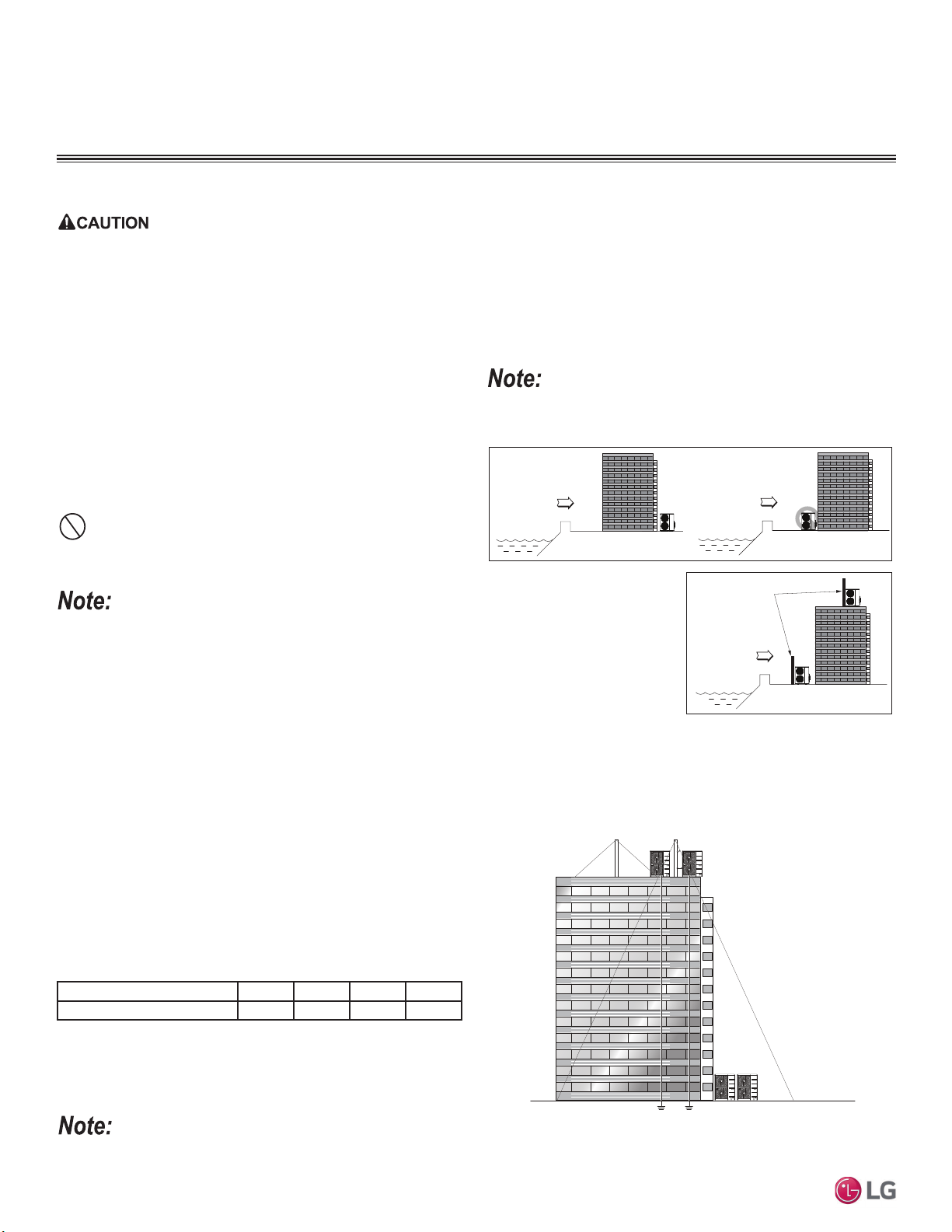
Ocean winds
Ocean winds
Ocean winds
Windbreaker
Oceanside Installation Precautions
• Install the outdoor unit on the side of the building opposite from
direct ocean winds.
• Select a location with good drainage.
• Periodically clean dust or salt particles off of the heat exchanger
with water.
Avoid installing the outdoor unit where it would be directly exposed to
ocean winds.
Additional anti-corrosion treatment will need to be applied to the outdoor
unit at oceanside locations.
If the outdoor unit must be
placed in a location where it
would be subjected to direct
ocean winds, install a concrete
windbreaker strong enough to
block any winds. Windbreaker
height and width must be more
than 150% of the outdoor unit,
and be installed at least 27-1/2
inches away from the outdoor
unit to allow for airflow.
Ocean winds will cause corrosion, particularly on the condenser and
HYDSRUDWRU¿QVZKLFKLQWXUQFRXOGFDXVHSURGXFWPDOIXQFWLRQRULQHI¿-
cient performance.
When deciding on a location to place the outdoor unit, be sure to choose an area where run-off from defrost will not accumulate and freeze on
sidewalks or driveways, which will create unsafe conditions. Properly install and insulate any drain hoses to prevent the hose from freezing, cracking,
leaking, and causing unsafe conditions from frozen condensate.
PLACEMENT CONSIDERATIONS
Planning for Snow and Ice, continued.
Tie-Downs and Lightning Protection
Tie-Downs
• The strength of the roof must be checked before installing the
outdoor units.
• If the installation site is prone to high winds or earthquakes, when
installing on the wall or roof, securely anchor the mounting base
using a field-provided tie-down configuration approved by a local
professional engineer.
• The overall tie-down configuration must be approved by a local
professional engineer. Always refer to local code when using a
wind restraint system.
Lightning Protection
• To protect the outdoor unit from lightning, it must be placed within
the specified lightning safety zone.
• Power cable and communication cable must be installed five (5)
feet away from lightning rod.
• A high-resistance ground system must be included to protect
against induced lightning or indirect strike.
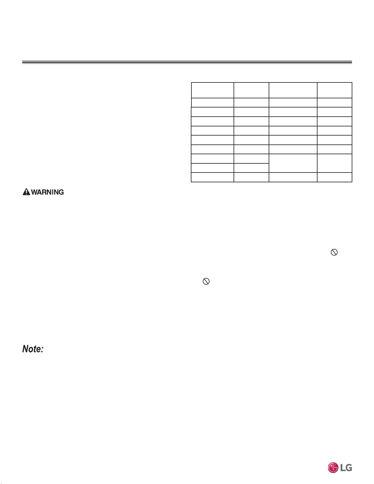
Table 8: 6DIHW\=RQH6SHFL¿FDWLRQV
Building Height (feet) 66 98 148 197
3URWHFWLRQ$QJOHÜ 55 45 35 25
Ground
Safe zone
Lightning rod
Protection Angle (25˚~55˚)
1.5m
1.5m
5 feet
Lightning rod
Figure 6: Lightning Protection Diagram.
If the building does not include lightning protection, the outdoor unit will be damaged from a lightning strike. Inform the customer of this possibility in
advance.
6HOHFWLQJWKH%HVW/RFDWLRQIRUWKH2XWGRRU8QLW
23
Installation
Due to our policy of continuous product innovation, some specifications may change without notification.
©LG Electronics U.S.A., Inc., Englewood Cliffs, NJ. All rights reserved. “LG” is a registered trademark of LG Corp.
MULTI
F
MAX
MULTI
F
PLACEMENT CONSIDERATIONS
6HOHFWLQJWKH%HVW/RFDWLRQIRUWKH2XWGRRU8QLW
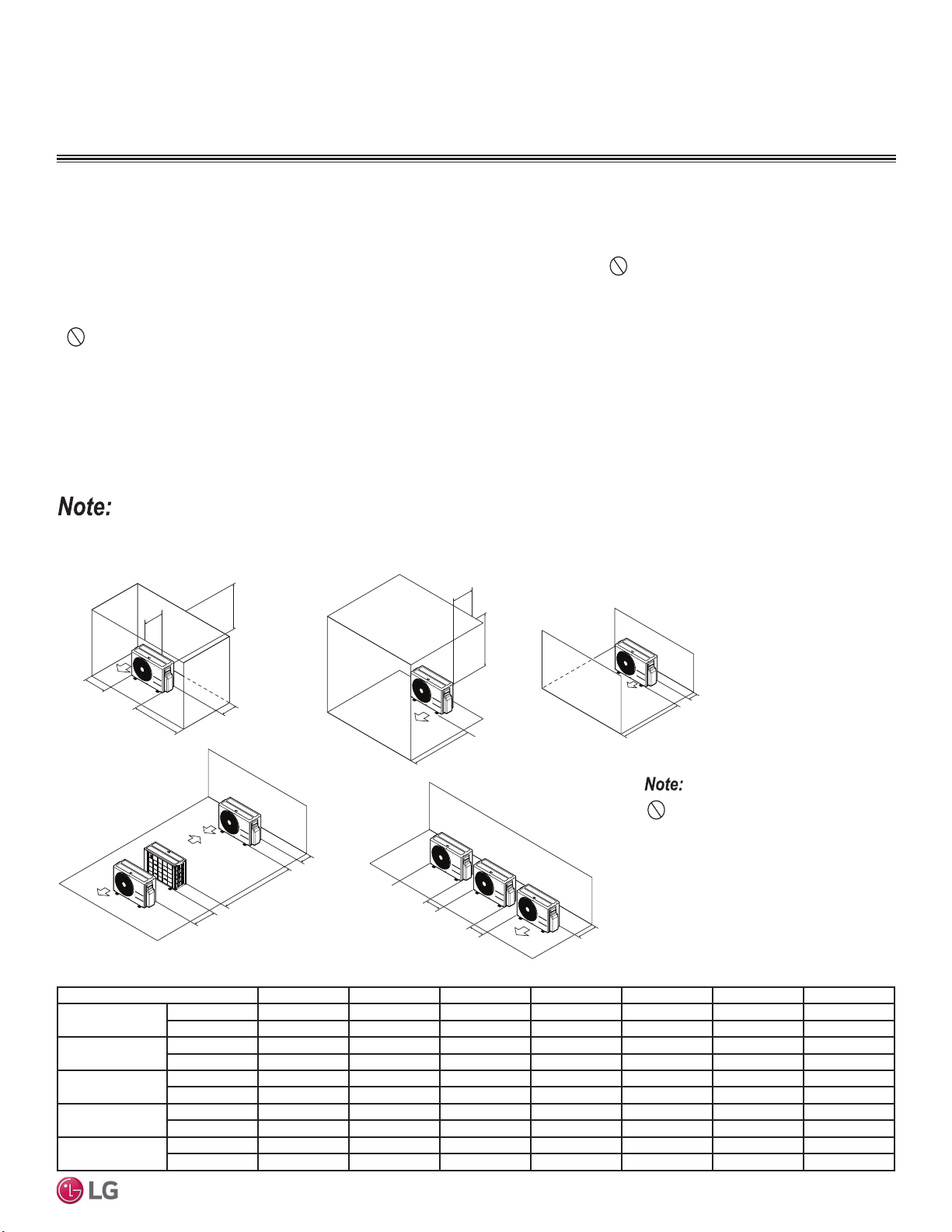
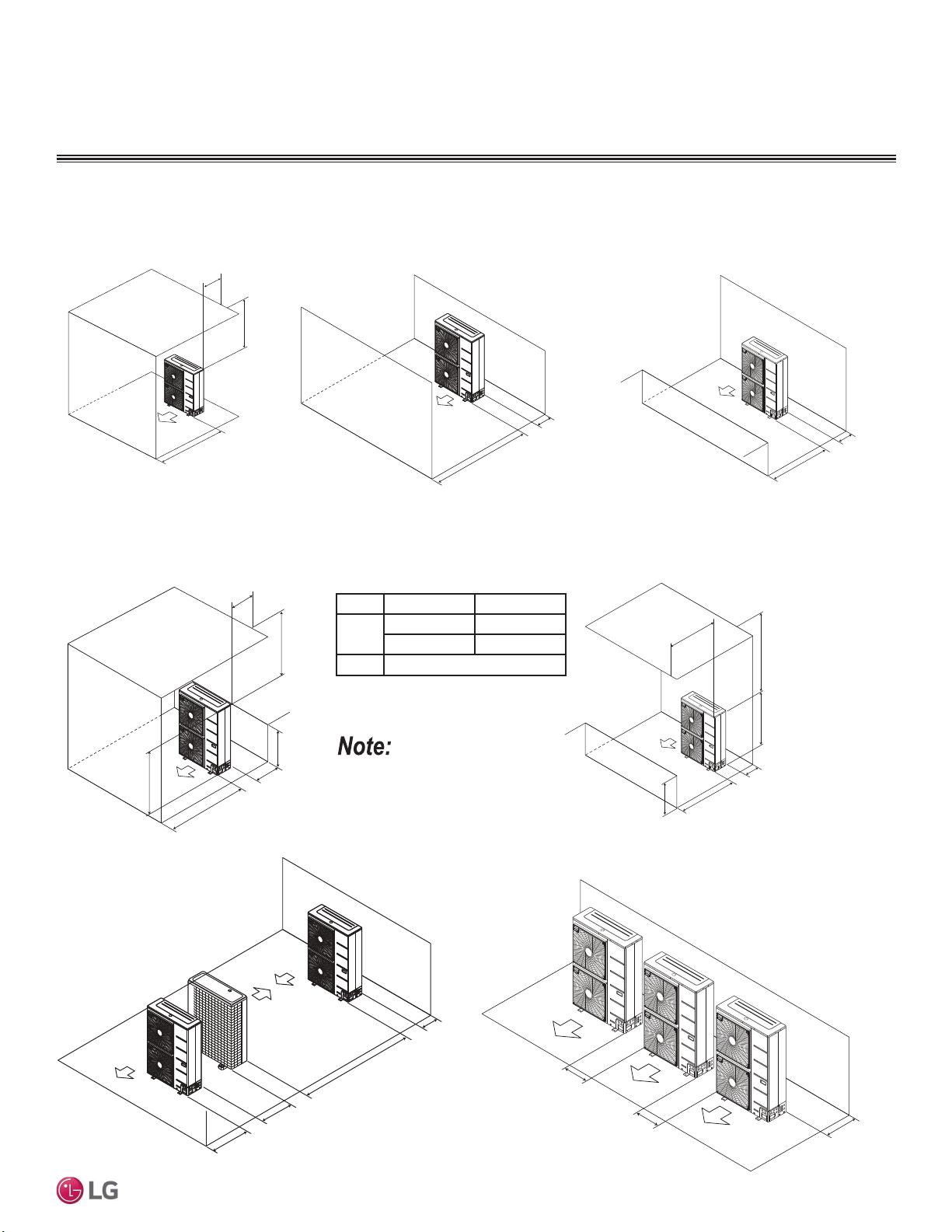
Multi F Outdoor Unit (18,000, 24,000, 30,000, and 36,000 Capacities) Service Access and Allowable Clearances
Specific clearance requirements in the diagram below are for 18,000, 24,000, 30,000, 36,000 Btu/h capacities. The figure below shows the
overall minimum clearances that must be observed for safe operation and adequate airflow around the outdoor unit.
When placing the outdoor unit under an overhang, awning, sunroof or other “roof-like structure”, observe the clearance requirements (as
shown in Cases 1 and 2) for height in relation to the unit. To have successful service access to the outdoor unit, see the figure below for
minimum spacing. When installing multiple outdoor units, see Cases 4 and 5 for correct spacing requirements.
Figure 7: Multi F 18,000, 24,000, 30,000, and 36,000 Capacity Outdoor Unit Service Access and Allowable Clearances Diagram.
Unit: Inch A B C D E F G
Case 1
Standard 12 24 - 12 - - -
Minimum 410- 4 - -40
Case 2
Standard --20----
Minimum --14---40
Case 3
Standard - - 20 12 - - -
Minimum --144---
Case 4
Standard ---1224--
Minimum ---4879-
Case 5
Standard -24-12- - -
Minimum -10- 4 - - -
Table 9: Multi F 18,000, 24,000, 30,000, and 36,000 Outdoor Unit Service Access and Allowable Clearances Diagram Legend.
Do not place the unit where animals
and/or plants will be in the path of the warm
air, or where the warm air and/or noise will
disturb neighbors.
If the outdoor unit is installed between standard and minimum clearances, capacity decreases approximately 10%.
Minimum Allowable Clearance and Service Access Requirements
Proper clearance for the outdoor unit coil is critical for proper operation. When installing the outdoor unit, consider service, inlet and outlet,
and minimum allowable space requirements as illustrated in the diagrams on the following pages.
• Include enough space for airflow and for service access. If installing multiple outdoor units, avoid placing the units where the discharge
of one unit will blow into the inlet side of an adjacent unit.
• If an awning is built over the unit to prevent direct sunlight or rain exposure, make sure that the discharge air of the outdoor unit isn’t
restricted.
•
No obstacles to air circulation around the unit; keep proper distances from ceilings, fences, floor, walls, etc. (Install a fence to prevent
pests from damaging the unit or unauthorized individuals from accessing it.)
A
B
D
G
C
G
C
D
E
D
D
B
B
F
1/16 inch
20 inches or less
Case 1
Case 4
Case 2 Case 3
Case 5
20 inches or less
24
MULTI F / MULTI F MAX Outdoor Unit Installation Manual
Due to our policy of continuous product innovation, some specifications may change without notification.
©LG Electronics U.S.A., Inc., Englewood Cliffs, NJ. All rights reserved. “LG” is a registered trademark of LG Corp.
MULTI
F
MAX
MULTI
F
PLACEMENT CONSIDERATIONS
6HOHFWLQJWKH%HVW/RFDWLRQIRUWKH2XWGRRU8QLW
Minimum 12
Air inlet grille
Blown
air
Strong
wind
Strong
wind
Minimum 12
Minimum 24
Sunroof
Fence or
obstacles
Minimum 12
Air inlet grille
Blown
air
Strong
wind
Strong
wind
Minimum 20
Fence or
obstacles
Unit: Inch
Minimum 12
Ensure that the space at the back of the outdoor unit is a minimum of 12 inches, and
include a minimum of 24 inches at the right side of the unit for service.
If the outdoor unit discharge side faces a wall, include a minimum of 20 inches between
the outdoor unit and the wall. Install the outdoor unit so that the discharge port is set at a
right angle to the wind direction.
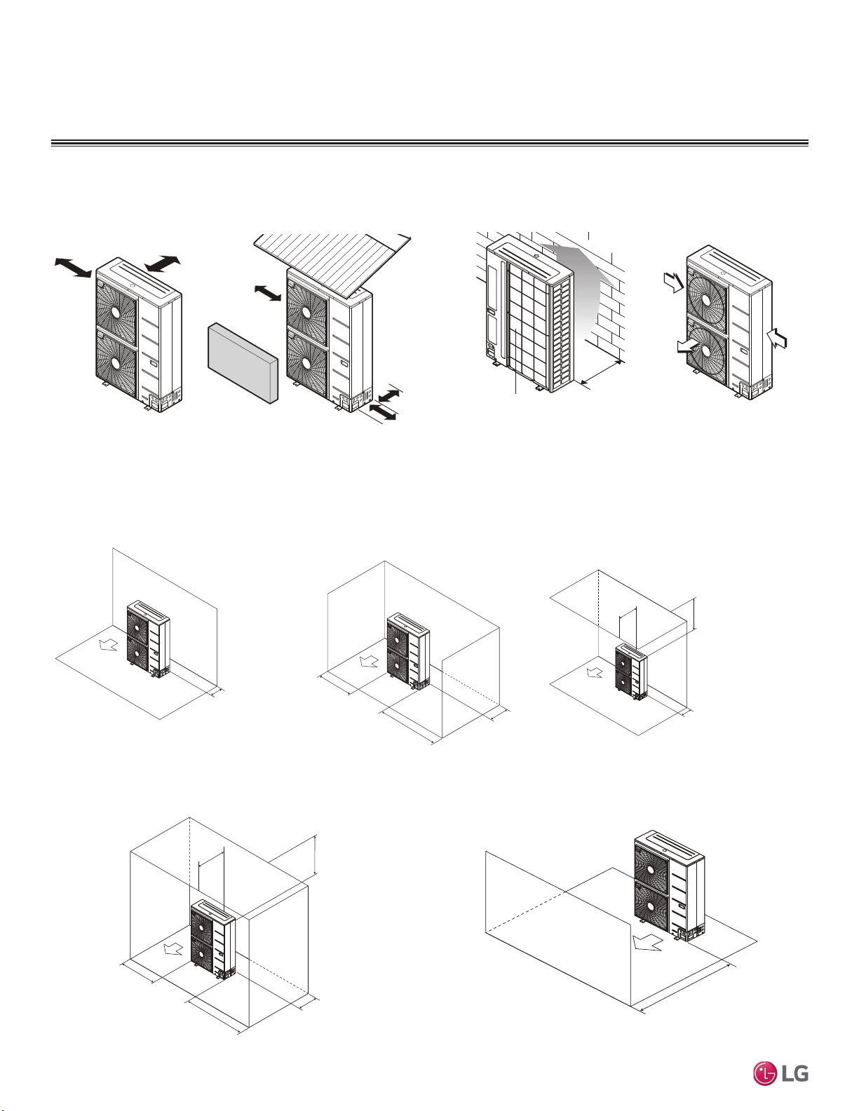
Multi F MAX Outdoor Unit (48,000, 54,000 and 60,000 Btu/h Capacity) Service Access and Allowable Clearances
When installing the outdoor unit, consider service, inlet, and outlet, and minimum allowable space requirements as illustrated in the following
diagrams.
Clearance Requirements when Different Obstacles are Present (Unit: Inch).
Minimum 12"
Minimum 20"
Minimum 40"
Obstacles above and on the air intake side
.
Minimum 12"
Maximum 20
"
Minimum 12"
Minimum 40"
Minimum 24"
Obstacles above, on the air intake side,
and on both left and right sides
Minimum 20"
Obstacle just on the
air discharge side.
Minimum 12"
Minimum 12"
Minimum 12"
Minimum 24"
Obstacle on the suction side only. Obstacles on the suction side and
on both left and right sides.
25
Installation
Due to our policy of continuous product innovation, some specifications may change without notification.
©LG Electronics U.S.A., Inc., Englewood Cliffs, NJ. All rights reserved. “LG” is a registered trademark of LG Corp.
MULTI
F
MAX
MULTI
F
PLACEMENT CONSIDERATIONS
6HOHFWLQJWKH%HVW/RFDWLRQIRUWKH2XWGRRU8QLW
Where there are obstacles on both suction
and discharge sides (discharge side obstacle
is higher than the outdoor unit).
Minimum 20
"
Minimum 12"
Table 10: Ratio among H, A, and L.
Clearance Requirements when Different Obstacles are Present, continued. (Unit: Inch)
If a stand is necessary, it must be contained (not
open frame) to prevent the discharge air from
short cycling.
LA
/+
/+ 30 inches
1/2 H < L 40 inches
H < L 6HW6WDQGDV/+
Where there are obstacles above, and on both
suction and discharge sides (discharge side obstacle
is higher than the outdoor unit).
Maximum 20"
Minimum 12"
Minimum 40"
L
H
A
L
Minimum 40"
Minimum 40"
Maximum 20"
Minimum 12"
Where there are obstacles above, and on both
suction and discharge sides (discharge side obstacle
is lower than the outdoor unit).
H
Minimum 12"
Minimum 79"
Minimum 24"
Minimum 40"
Series installation
³/´PXVWEHORZHUWKDQ³+´,IDVWDQG
is necessary, it must be contained (not
open frame) to prevent the discharge air
from short cycling.
Where there are obstacles on both suction
and discharge sides (discharge side obstacle
is lower than the outdoor unit).
Minimum 20"
Minimum 12"
Minimum 20"
Minimum 20"
Minimum 40"
Obstacles above and on the
air discharge side.
Minimum 12"
Minimum 24"
Minimum 24"
Side-by-side series installation.

26
MULTI F / MULTI F MAX Outdoor Unit Installation Manual
Due to our policy of continuous product innovation, some specifications may change without notification.
©LG Electronics U.S.A., Inc., Englewood Cliffs, NJ. All rights reserved. “LG” is a registered trademark of LG Corp.
MULTI
F
MAX
MULTI
F
PLACEMENT CONSIDERATIONS
Installing Outdoor Units Indoors
LG Multi F / Multi F MAX outdoor units are engineered to be mounted outdoors and include technology designed to minimize the negative
effects of winter weather’s freezing rain, sleet, and snow. Some building projects, however, necessitate placing the HVAC outdoor units
indoors:
• Lack of ground space.
• Lack of an appropriate outdoor location that meets system design requirements.
• When mounting on the roof is not an option due to a lack of roof space.
• Roof warranty will be voided if mechanical equipment is placed on the membrane.
• On retrofit projects, a former chiller / boiler / air handler equipment room, mechanical area, or penthouse already exists.
• To curtail the potential need for redundant zone heating devices such as wall-fin radiators or duct heaters.
• In extremely cold environments where there is a significant amount of run-time at temperatures well below freezing outside the outdoor unit
ambient air temperature range published in this engineering manual.
Benefits of Installing Outdoor Units Indoors
• Shelters the outdoor unit from direct exposure to prevailing winds that decrease the heating capability of the outdoor unit.
• Protects equipment from freezing precipitation and/or potential ice build-up that could hinder unit operation.
• Maintains coil heat transfer efficiency by reducing the number of and shortening the cycle time for defrost operation.
• Easier maintenance and servicing during inclement weather.
• When mounted in a fully enclosed space, limiting the ambient air temperature will allow the Multi F / Multi F MAX system designer to elimi-
nate oversizing.
• The outdoor unit to compensate for loss of capacity at low ambient temperatures.
• Will also curtail the need to provide inefficient redundant zone heating devices such as wall-fin radiators and second-stage ancillary heating
devices.
Design Considerations Include:
• Enclosure types and elements such as louvers (see next page), rain hoods, dampers and controls, heating methods and sizing of heating
devices.
• Heating strategies.
• Duct design.
• Condensate handling.
General Guidelines
• Follow ASHRAE 62.1 design guidelines.
• Depending on the project / application, a roof over the outdoor units in combination with a wind break will be all that is necessary.
• Consider the potential for snow accumulation near louvers / roof openings. Outside air intakes and discharge ducts/louvers must be engi-
neered to clear anticipated snow accumulation levels by at least one (1) foot.
• ,QVLWXDWLRQVZKHUHRSHUDWLRQLVDQWLFLSDWHGDWWHPSHUDWXUHVRI)DQGORZHUDQFLOODU\KHDWPXVWEHSURYLGHGWRKHDWWKHRXWGRRUXQLW
coils to assure continuous compressor operation and heating.
It will be necessary to use a field-fabricated air guide to prevent discharge air from short-cycling back to the coil inlet.
• Consider the direction of prevailing winds and opening placement. If possible, locate inlet openings upwind of discharge openings and other
exhaust outlets.
• When inlet and outlet openings are placed on the same wall, minimum distance between the two openings must be approximately three (3)
feet (minimum distance varies significantly with variations in outlet opening face velocity).
• If roof-mounted ventilation openings are used, strategically locate the inlet ventilation opening(s) upwind of the outlet opening(s).
• Discharge and supply ductwork must be designed to avoid weather related long periods of water entrainment and the potential for microbial
growth.
6HOHFWLQJWKH%HVW/RFDWLRQIRUWKH2XWGRRU8QLW
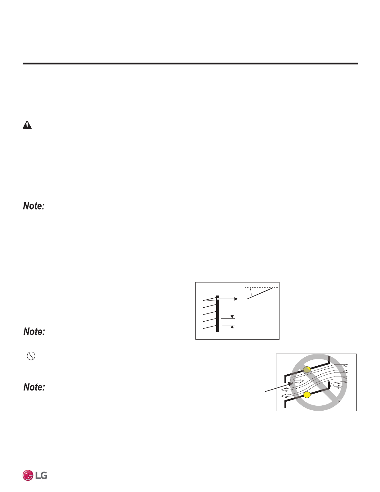
27
Installation
Due to our policy of continuous product innovation, some specifications may change without notification.
©LG Electronics U.S.A., Inc., Englewood Cliffs, NJ. All rights reserved. “LG” is a registered trademark of LG Corp.
MULTI
F
MAX
MULTI
F
1. Outdoor Unit Enclosure: Manual Door Open Type.
2. /RXYHU$QJOH1R0RUH7KDQ+RUL]RQWDOO\
3. Space Between Louvers: More than 4 inches (Recommend).
4. Louver Shape: Wing or Plane Type.
Inside
Outside
Air flow passing through
the louver blade backwards
can generate noise.
In
side
Maximum 15°
(Recommended)
More than 4 in.
(Recommended)
Louver
• Open Rate and Inlet must be taken into consideration when design-
ing the louvered outdoor unit enclosure.
• 'RQRWXVH³6´W\SHORXYHUV
If the Louver Open Rate is Too Small
1. Noise can occur because of the increased air velocity passing
through the louver blade.
2. Noise can occur from louver blade vibrations.
3. A drop in outdoor unit fan performance (excess static pressure can
cause a drop in outdoor unit performance and heat exchanger ef-
ficiency).
4. If the louver open rate is too small or there is insufficient air flow
exchange, the air conditioner might stop operating.
Figure 8: Louver Recommendations.
Figure 9: Using “S” Type Louvers.
Provide a means to drain the condensate generated during heating mode and defrost cycle in addition to rainwater that infiltrates the inlet
louver enclosed area.
• Install a field-provided drain pan under the outdoor units and provide a path to a nearby floor drain.
• ,IWKHDPELHQWDLUWHPSHUDWXUHLVH[SHFWHGWRGURSEHORZ)LQWKHHQFORVXUHKHDWWKHERWWRPVXUIDFHRIWKHSDQGUDLQOLQHDQGIORRU
drain so that the condensate does not freeze before reaching the drain.
Louver Recommendations for Outdoor Unit Enclosure
Allow for ventilation intake and exhaust air based on maximum outdoor unit fan capacity.
• Select the size, type and orientation of architectural louvers with adequate “net free area” face velocity to ensure the total external static
pressure from the outdoor unit fan does not exceed design limitations (see specification data tables).
• No obstructions must be placed in front of the louver that could hamper the free flow (throw) of air.
• Roof top openings and / or discharge and supply louvers must be equipped with screens to prevent bird and insect infiltration.
For louver recommendations, see below and on the next page.
As always, the best solution for each project balances acceptable heating performance (considering local weather conditions), capital costs,
life cycle energy consumption, and limitations set forth by local building codes.
When deciding on a location to place the outdoor unit, be sure to choose an area where run-off from defrost will not accumulate and freeze on side-
walks or driveways which will create unsafe conditions.
CAUTION
PLACEMENT CONSIDERATIONS
6HOHFWLQJWKH%HVW/RFDWLRQIRUWKH2XWGRRU8QLW
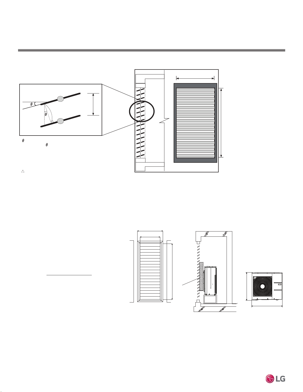
28
MULTI F / MULTI F MAX Outdoor Unit Installation Manual
Due to our policy of continuous product innovation, some specifications may change without notification.
©LG Electronics U.S.A., Inc., Englewood Cliffs, NJ. All rights reserved. “LG” is a registered trademark of LG Corp.
MULTI
F
MAX
MULTI
F
Figure 10: Open Rate by Louver Radian Formula.
Side View
ho = h * COS
Total Area (A) = H * W
Number of Open Spaces (N) = (Number of Louvers - 1)
Effective Area (Af) = ho * W * N
Louver Open Rate (n) = Af / A
Af = A * n
Effective Cross Section Area
ho
h
W
Front View
H
Open Rate by Louver Radian
PLACEMENT CONSIDERATIONS
6HOHFWLQJWKH%HVW/RFDWLRQIRUWKH2XWGRRU8QLW
55-1/8
47-1/4
37-3/8
74-13/16
32-13/16
Unit: Inch
Air Guide Duct
Louver Dimensions Air Guide Duct on
Outdoor Unit
Outdoor Unit
Dimensions
Formula
• Total Louver Dimension (Excluding Frame) (A) = 3.9 feet x 6.2 feet = 24.2 ft.
2
• Louver Shield Dimension by Product (B) = 3.12 feet x 2.74 feet = 8.55 ft.
2
• Inlet Louver Dimension (A - B) = 15.7 ft.
2
• Equivalent Inlet Dimension (Open Rate 80%) = 15.7 ft
2
x 0.8 = 12.56 ft.
2
• Equivalent Inlet Air Volume = 12.56 ft.
2
x 8.2 ft./s x 60 sec./min. = 6,179.5 ft.
3
/min.
• Required Air Volume / Equivalent Volume = 6,179.5 ft.
3
/min. / 2,119 ft.
3
/min. = 291% (Within Allowable Limits)
Confirming Air Flow Rate / Total Opening Rate
• Example: LMU36CHV
• Airflow Rate: 2,119 ft.
3
/min.
• Velocity of Outlet Air: 16.4 ft./s
• Velocity of Inlet Air: 8.2 ft./s
• Open Rate = 80% or More
• Discharge Air Guide must be installed.
Figure 11: Example of Installing Outdoor Unit Indoors.
Open Rate = Effective Face Area (Af)
Total Face Area (A)
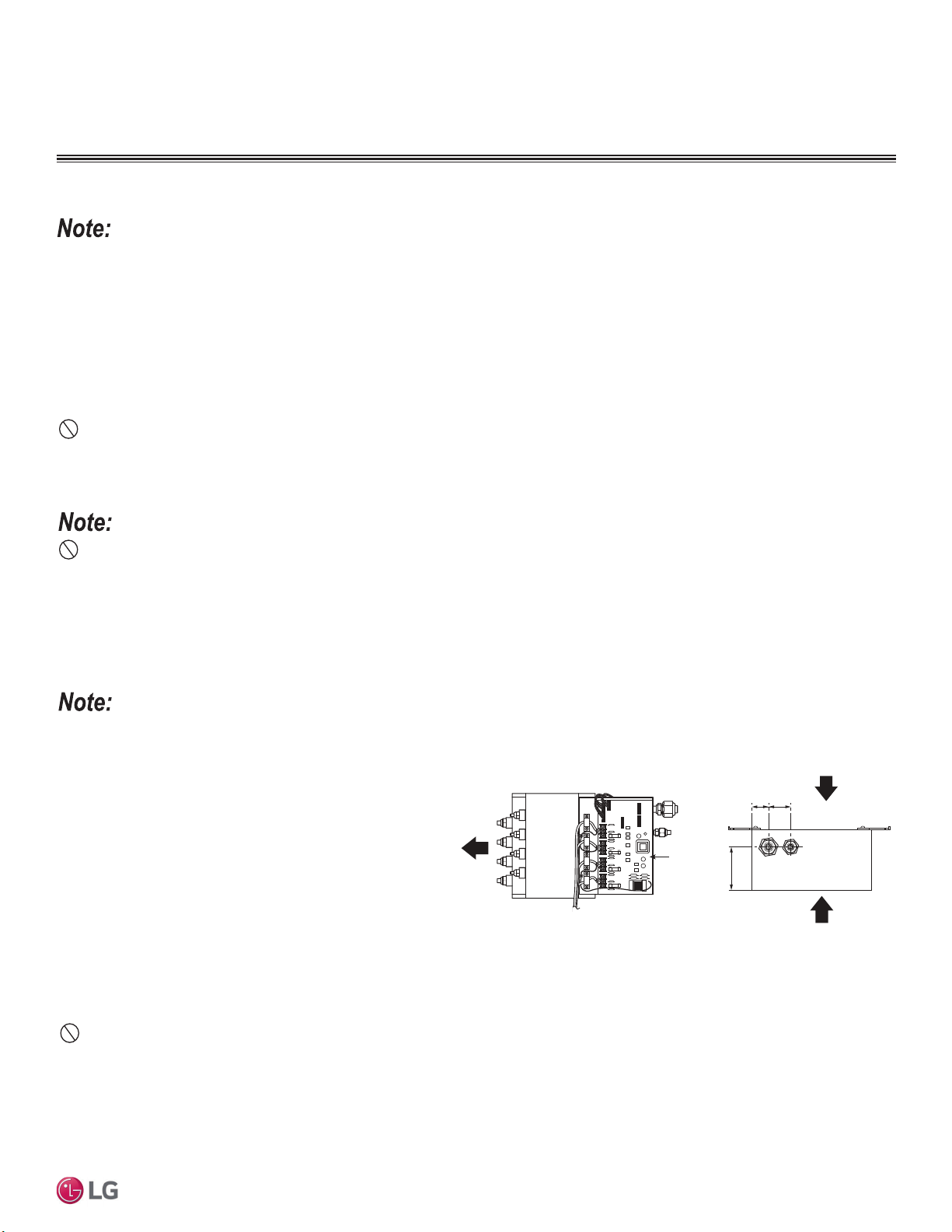
29
Installation
Due to our policy of continuous product innovation, some specifications may change without notification.
©LG Electronics U.S.A., Inc., Englewood Cliffs, NJ. All rights reserved. “LG” is a registered trademark of LG Corp.
MULTI
F
MAX
MULTI
F
Selecting the Best Location for the Indoor Units
Select a location for installing the indoor units that will meet the following conditions:
• Within allowable parameters for proper connection to the outdoor unit (and branch distribution unit, if a Multi F MAX system).
• So that condensation drainage can be conveniently routed away.
• Include enough space around the indoor unit so that it is accessible for maintenance and service purposes.
• Where electrical noise / electromagnetic waves will not affect indoor unit operation. Maintain proper distances between the indoor units and
electric wires, audio and visual appliances, breaker / circuit panels, etc. If the frequency signal of the appliance is unstable, then install the
indoor unit a minimum of ten (10) feet away, and run the power and transmission cables through a conduit.
• An area that is level and with enough strength to bear the weight of the indoor unit(s).
Do Not’s
• Install in an area with obstacles to air circulation around the unit; keep proper distances from ceilings, doorways, floor, walls, etc.
• Install in an area where operation sound will disturb occupants.
• Install in an area that exposes the indoor unit(s) to heat, water, steam, oil splattering or spray.
Selecting the Best Location for the Branch Distribution (BD) Units
Branch distribution (BD) units are used only with Multi
F MAX systems to distribute the refrigerant from the
outdoor unit up to eight (8) indoor units.
Select a location indoors that will meet the following
conditions:
• Within allowable parameters for proper connection
to the Multi F MAX outdoor unit and indoor unit(s);
refrigerant piping and wire lengths must not exceed
amounts specified by LG Electronics, U.S.A., Inc.
• Condensate drain piping is not required.
• Ensure there is enough space in the installation
area for service purposes (minimum 24 inches);
install the refrigerant piping and electrical wiring
system in an easily accessible location.
• Level where there is enough strength to bear the weight of the branch distribution unit.
Do Not’s
• Install the branch distribution unit in a location where it would be subjected to strong radiation heat from heat sources.
• Install in an installation environment where the branch distribution unit would be exposed to heat, water, steam, oil splattering or spray.
• Install the unit in a location where any sound it generates will disturb occupants in the surrounding rooms.
• ,QVWDOOLQDORFDWLRQZKHUHWKHUHDUHREVWDFOHVWRDLUFLUFXODWLRQDURXQGWKHXQLWNHHSSURSHUGLVWDQFHVIURPFHLOLQJVGRRUZD\VÀRRUZDOOVHWF
• Install in an area where high-frequency electrical noise / electromagnetic waves will affect operation. Maintain proper distances between the
branch distribution unit(s) and electric wires, audio and visual appliances, breaker / circuit panels, etc.
Indoor units (IDUs) must not be placed in an environment where the IDUs will be exposed to harmful volatile organic compounds (VOCs) or in
environments where there is improper air make up or supply or inadequate ventilation. If there are concerns about VOCs in the environment where
the IDUs are installed, proper air make up or supply and / or adequate ventilation must be provided. Additionally, in buildings where IDUs will be
exposed to VOCs consider a factory-applied epoxy coating to the fan coils for each IDU.
)RUGHWDLOHGSODFHPHQWFRQVLGHUDWLRQVDQGLQVWDOODWLRQUHTXLUHPHQWVIRULQGRRUXQLWVUHIHUWRLWV,QGRRU8QLW(QJLQHHULQJDQG
or Installation Manuals.
PLACEMENT CONSIDERATIONS
6HOHFWLQJWKH%HVW/RFDWLRQIRUWKH,QGRRU8QLWV
%UDQFK'LVWULEXWLRQ8QLWV
PCB
1-31/321-3/16
4-3/8
Service Direction
Piping to
Indoor Units
Service Direction
Figure 12: %UDQFK'LVWULEXWLRQ8QLW.H\&RPSRQHQWV
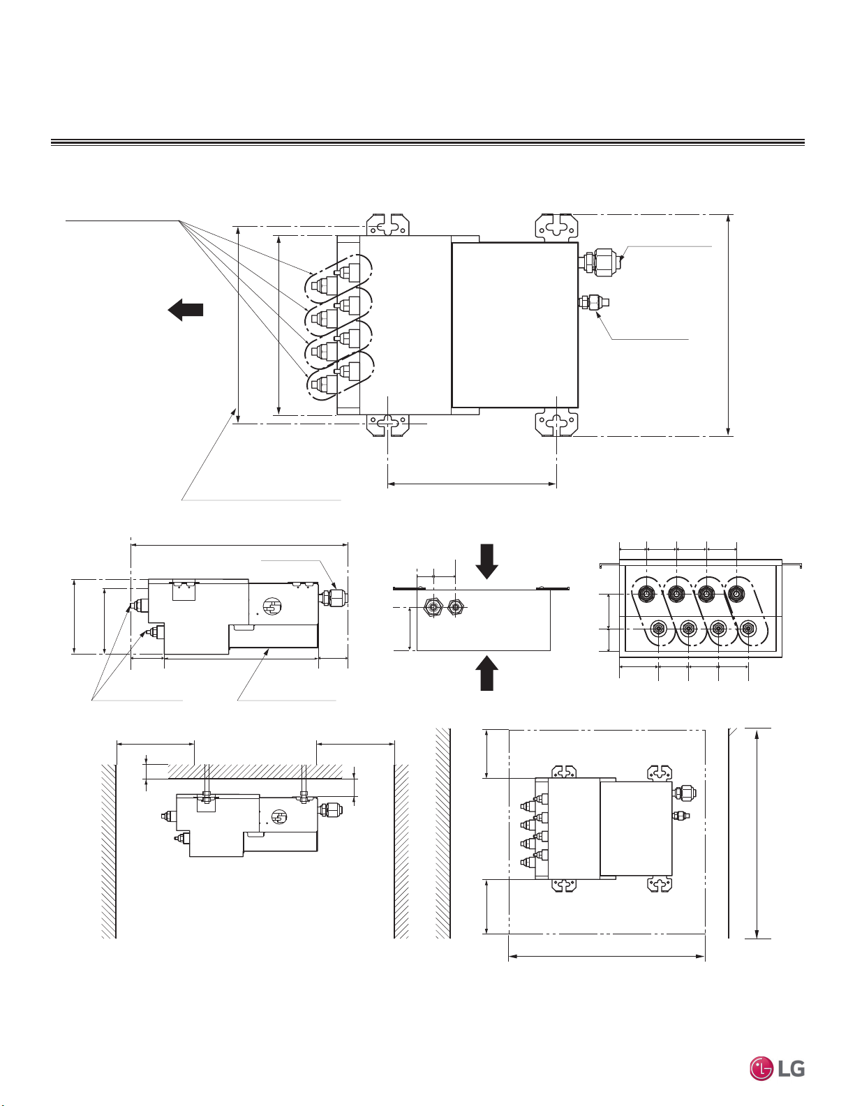
30
MULTI F / MULTI F MAX Outdoor Unit Installation Manual
Due to our policy of continuous product innovation, some specifications may change without notification.
©LG Electronics U.S.A., Inc., Englewood Cliffs, NJ. All rights reserved. “LG” is a registered trademark of LG Corp.
MULTI
F
MAX
MULTI
F
Mininum 1-3/16
Mininum 3-15/16
Minimum 15-3/4
Branch Pipe
17
6-5/16
Cover Control
Main Pipe
Service Space
EEV Service
Controller Service
Inspection Opening
Minimum 12
Minimum 12
11-23/32
9-27/32
Ø3/4
Ø3/8
Suspension Bolt Pitch
9-21/32
13-9/32
Indoor Unit
Piping Direction
Unit: Inch
Minimum 24
Minimum 24
Bottom View
Minimum 15-3/4Mininum 15-3/4
Side View
5-29/32
2-27/32
11-13/16
2-3/8
1-3/16
1-31/32
4-3/8
A-C (and PMBD3640 D) Connections:
Liquid Pipe Ø1/4
Gas Pipe Ø3/8
PMBD3641 D Connections:
Liquid Pipe Ø1/4
Gas Pipe Ø1/2
Notes:
1. For PMBD3620 Unit, Ports A and B are Available.
2. For PMBD3630 Unit, Ports A, B, and C are Available.
3. For PMBD3640 and PMBD3641 Units, Ports A, B, C, and D are Available.
ABCD
1-1/2 1-31/32
1-23/32
1-31/32
1-31/32
1-31/32
1-31/32
1-31/32
1-31/32
2-7/32
PLACEMENT CONSIDERATIONS
6HOHFWLQJWKH%HVW/RFDWLRQIRUWKH%UDQFK'LVWULEXWLRQ8QLWV
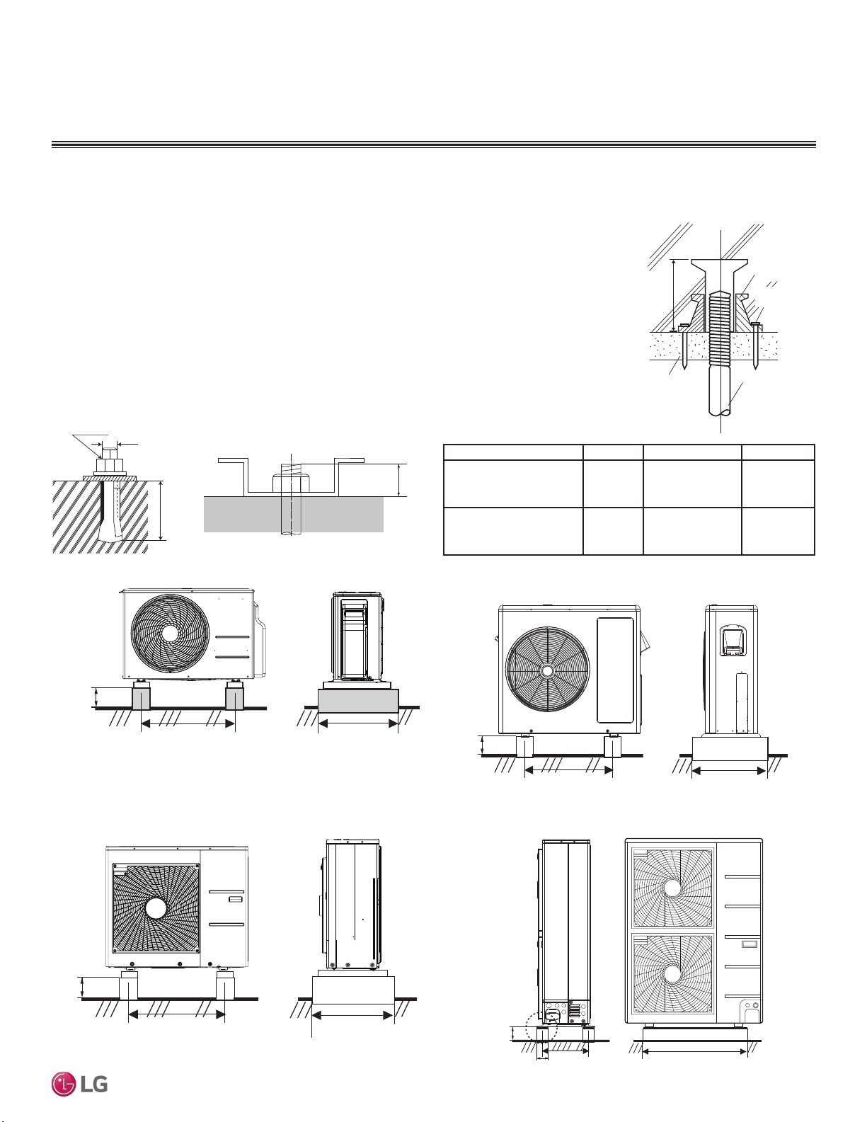
31
Installation
Due to our policy of continuous product innovation, some specifications may change without notification.
©LG Electronics U.S.A., Inc., Englewood Cliffs, NJ. All rights reserved. “LG” is a registered trademark of LG Corp.
MULTI
F
MAX
MULTI
F
02817,1*$1&+25,1*
THE OUTDOOR UNITS
0RXQWLQJ$QFKRULQJWKH2XWGRRU8QLW*HQHUDO
Specifications
• Tightly anchor the outdoor unit with a bolt and nut to a concrete or rigid platform.
• :KHQLQVWDOOLQJRQDZDOOZLWK¿HOGVXSSOLHGEUDFNHWVURRIRUURRIWRSVHFXUHO\DQFKRUWKHPRXQWLQJ
platform with nails and / or wiring, taking into consideration the possibility of strong winds or earthquakes.
• If installing the outdoor unit on the roof, check the strength of the roof.
M10
Anchor Bolt
3
13/16
Unit: Inch
Figure 13: Example of Using an
Insert for a Hole in a Reinforced
Concrete Beam.
Concrete Beam
Insert
Suspension Bolt
Polyblock /
Anti-Vibration
Material
Nail Securing
Polyblock
Figure 14: Close up of Bolt Attachment.
Outdoor Unit Platform Concrete Specifications
• Concrete foundations must be made of one part cement, two parts sand, and four parts gravel.
• The surface of the foundation must be finished with mortar with rounded edges, and weatherproofed.
• See table and figures for height, width, etc., requirements.
• Include an area for drainage around the foundation to ensure condensate thoroughly drains away from
the outdoor unit.
Outdoor Unit Bolt Type Concrete Height Bolt Depth
LMU180HV, LMU18CHV,
LMU240HV, LMU24CHV,
LMU30CHV, LMU36CHV
M10-J
Minimum Four (4)
Inches
Minimum
Three (3)
Inches
LMU480HV, LMU540HV,
LMU600HV
M10-J
Minimum Eight
(8) Inches
Minimum
Three (3)
Inches
Table 11: 2XWGRRU8QLW)RXQGDWLRQ6SHFL¿FDWLRQV
Figure 15: LMU180HV and LMU240HV Outdoor Units.
Minimum
8
7-7/8
15-3/4
Minimum 24-13/32
Unit: Inch
Figure 16: LMU18CHV and LMU24CHV Outdoor Units.
Minimum
3-15/16
21-1/2
Minimum 14-9/16
Unit: Inch
Minimum 4
21-1/2
Minimum 15
Unit: Inch
Figure 17: LMU30CHV and LMU36CHV Outdoor Units.
Figure 18: LMU480HV, LMU540HV, LMU600HV Outdoor Units.
B or
more
A
C
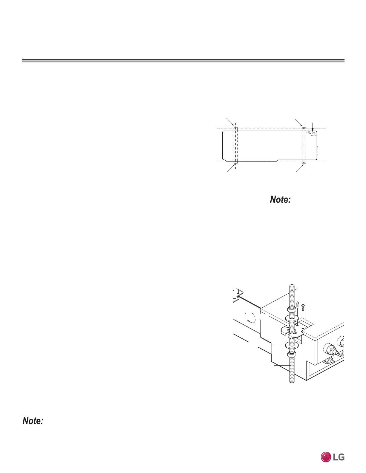
32
MULTI F / MULTI F MAX Outdoor Unit Installation Manual
Due to our policy of continuous product innovation, some specifications may change without notification.
©LG Electronics U.S.A., Inc., Englewood Cliffs, NJ. All rights reserved. “LG” is a registered trademark of LG Corp.
MULTI
F
MAX
MULTI
F
Branch Distribution Unit Orientation
Multi F MAX branch distribution (BD) units can be installed in a multitude of options to fit various building
configurations and job or application requirements (suspended from the ceiling or mounted on the wall).
The installation location of the PCB within the branch distribution unit can be changed for easier service
access, depending on the branch distribution unit installation itself (see the wiring section for informa-
tion). Branch distribution units include electronic expansion valves that properly seat only if the branch
distribution unit is installed in an acceptable orientation. Installations with improper branch distribution
unit orientation risk incomplete valve seating and system performance degradation from potential refrig-
erant leakage through the electronic expansion valve.
This material is for informational
or educational purposes only. It is
not intended to be a substitute for
professional advice. Consult with
your engineer or design profes-
VLRQDOVIRUVSHFL¿FDSSOLFDWLRQVWR
your system.
Ceiling Mount Installation - Hangers with
Hanging Bolt
1. Drill four (4) holes in the ceiling, following the dimensions on the previous page.
2. Attach the factory-supplied hangers with two (2) screws each at the designated four
(4) areas on the frame of the branch distribution unit.
3. Install an anchor in the ceiling, and attach the hanging bolts to the ceiling.
4. Add nuts and washers to the hanging bolt as shown at right.
5. Hang the branch distribution unit on the hanging bolts (ceiling side up), and after
checking for level (±5 degrees), securely tighten all nuts.
BD unit
Nu t
(M10 or M8
Nut
(M10 or M8)
Flat washerFlat washer
Hanging bol tHanging bolt
(M10 or M8)
Figure 19: Branch Distribution Ceiling Mount
Installation.
If a screw has been installed on the frame of the branch distribution unit and the screw has been removed, to prevent condensation, either re-install
the screw or cover the open hole with aluminum tape.
Ceiling Mount Installation - Hangers Only
1. Attach the factory-supplied hangers with two (2) screws each at the designated four
(4) areas on the frame of the branch distribution unit.
2. Install the branch distribution unit to the ceiling using two screws on each of the
hangers as shown below. Unit must be ±5 degrees of level.
3. Cover parts of the hanger holes with polyethylene foam insulation (to prevent con-
densation).
02817,1*$1&+25,1*7+(
287'225%5$1&+',675,%87,2181,76
Bolting the Outdoor Unit to the Platform Procedure
1. Ensure that the concrete platform will not degrade easily, and has enough
strength to bear the weight of the unit.
2. Include an H-beam support. Firmly attach the corners, otherwise the support
will bend.
3. Use a hexagon nut.
4. If there is a possibility of vibration from the outdoor unit transmitting to the
building, add an anti-vibration material to the platform.
5. Include enough space around the concrete foundation for condensate drain-
age.
6. Seal all wiring and piping access holes with field-supplied sealing material to
prevent animals and bugs from entering the unit.
Figure 20: Bolting the Outdoor Unit to the Platform (Piping
Location Will Differ Depending on Outdoor Unit Model).
Bolt
Refrigerant Pipe
Connection Location
Top of Outdoor Unit
(Looking Down)
Bolt
Bolt
Bolt
Mounting / Anchoring the Outdoor Unit General Specifications, continued.
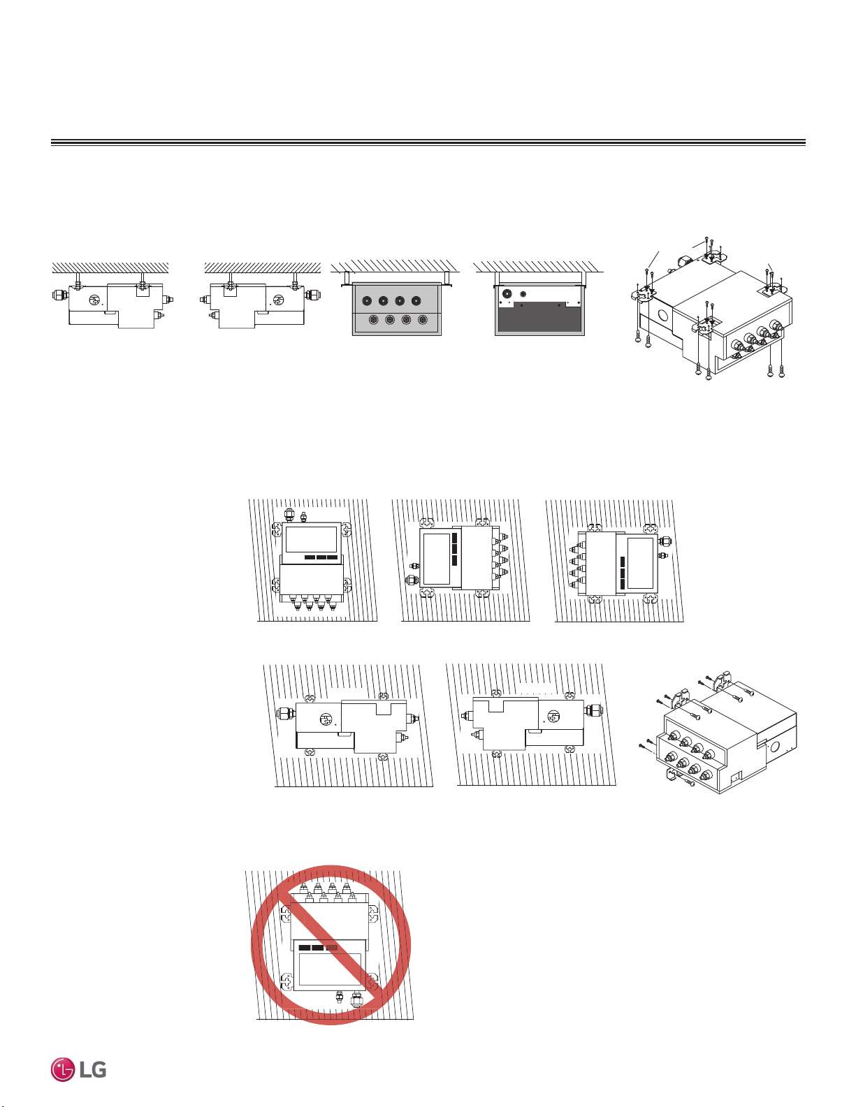
33
Installation
Due to our policy of continuous product innovation, some specifications may change without notification.
©LG Electronics U.S.A., Inc., Englewood Cliffs, NJ. All rights reserved. “LG” is a registered trademark of LG Corp.
MULTI
F
MAX
MULTI
F
Bottom of Unit
Wall
Bottom View, Port End Facing Up
PCB
Bott
Figure 22: Acceptable Branch Distribution Unit Orientation.
Wall Mounting Options
Wall
Bottom View, Port End Down
PCB
PCB
Wall
Bottom
of Unit
PCB
Wall
Bottom View, Port End Facing Right
Bottom
of Unit
Bottom of Unit
Into the
Wall
Into the Unit
Into the Unit
Into the Wall
Into the Wall
Bottom of Unit
Isometric View
Bottom View, Port End Facing Left
Wall
Left Side View, Port End Facing Left
Wall
Top of Unit
Top of Unit
Right Side View, Port End Facing Right
Figure 23: Unacceptable Branch Dis-
tribution Unit Wall Mount Orientations.
1. Attach the factory-supplied
hangers with two (2) screws
each at the designated four
(4) areas on the frame of the
branch distribution unit.
2. Install the branch distribution
unit to the wall using two
screws on each of the hang-
ers. Unit must be ±5 degrees
of level.
3. Cover parts of the hanger
holes with polyethylene
foam insulation (to prevent
condensation).
02817,1*$1&+25,1*
THE BRANCH DISTRIBUTION UNITS
Figure 21: Acceptable Branch Distribution Unit Ceiling Mount Orientations.
Left Side View,
Port End Facing Left
Ceiling Mounting Options
Port End View
Right Side View,
Port End Facing Right
Ceiling Ceiling
Ceiling
Top of Unit
Refrigerant Piping End View
Ceiling
Top of Unit
Top of Unit
Top of Unit
Top of Unit
Into the Ceiling
Into the Unit
Into the Ceiling
Into the Unit
Into the Unit
Into the Ceiling
Isometric View
Wall Mount Installation - Hangers Only
Ceiling Mount Installation, continued.
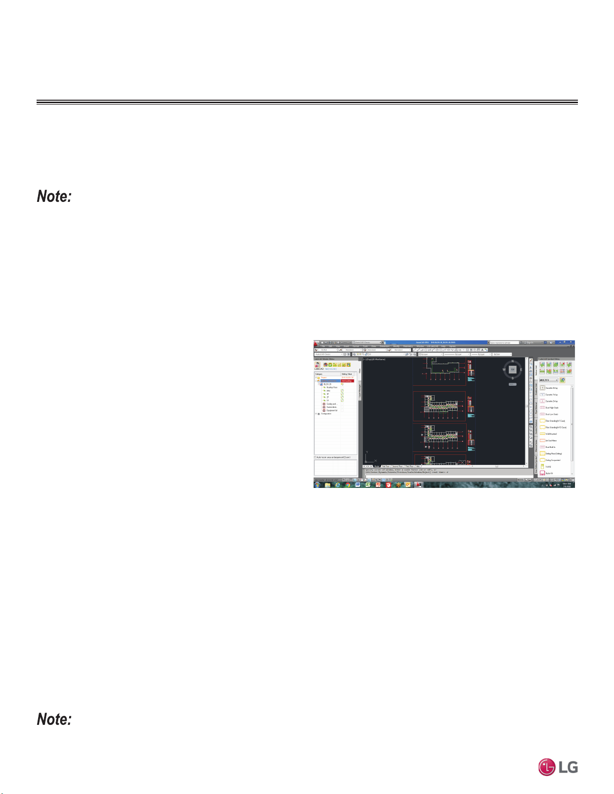
34
MULTI F / MULTI F MAX Outdoor Unit Installation Manual
Due to our policy of continuous product innovation, some specifications may change without notification.
©LG Electronics U.S.A., Inc., Englewood Cliffs, NJ. All rights reserved. “LG” is a registered trademark of LG Corp.
MULTI
F
MAX
MULTI
F
LG Air Conditioner Technical Solution (LATS) Software
A properly designed and installed refrigerant piping system is critical to the optimal performance of LG air-conditioning systems. To assist
engineers, LG offers, free of charge, LG Air Conditioner Technical Solution (LATS) software—a total design solution for LG air conditioning
systems.
To reduce the risk of designing an improper applied system or one that will not operate correctly, LG prefers that LATS software be used on all
projects.
Formats
LATS is available to LG customers in three user interfaces: LATS HVAC, LATS CAD2, and LATS Revit. All three LATS formats are available
through www.myLGHVAC.com, or contact an LG Sales Representative.
LATS HVAC is a Windows®-based application that aids engineers in designing LG Variable Refrigerant Flow (VRF), Multi F / Multi F MAX,
Multi F / Multi F MAX with LGRED, Single-Zone, and Energy Recovery Ventilator (ERV) systems.
*Windows
®
is a registered mark of Microsoft
®
Corporation.
LATS CAD2 combines the LG LATS program with AutoCAD® soft-
ware**. It permits engineers to layout and validate LG Multi V Vari-
able Refrigerant Flow (VRF), Multi F / Multi F MAX, Multi F / Multi
F MAX with LGRED, Single-Zone, and Energy Recovery Ventilator
(ERV) systems directly into CAD drawings.
LATS Revit integrates the LG LATS program with Revit
®
software**.
It permits engineers to layout and validate Multi V VRF systems
directly into Revit drawings.
**AutoCAD® and Revit® are both registered marks of Autodesk, Inc.
Features
All LG product design criteria have been loaded into the program, making LATS simple to use: double click or drag and drop the component
choices. Build systems in Tree Mode where the refrigerant system can be viewed. Switch to a Schematic diagram to see the electrical and
communications wiring.
LATS software permits the user to input region data, indoor and outdoor design temperatures, modify humidity default values, zoning, specify
type and size of outdoor units and indoor units, and input air flow and external static pressure (ESP) for ducted indoor units.
The program can also:
LG AIR CONDITIONER
TECHNICAL SOLUTION (LATS)
• Import building loads from a separate Excel file.
• Present options for outdoor unit auto selection.
• Automatically calculate component capacity based on design
conditions for the chosen region.
• Verify if the height differences between the various system
components are within system limits.
• Provide the correct size of each refrigerant piping segment and LG
Y-Branches and Headers.
• Adjust overall piping system length when elbows are added.
• Check for component piping limitations and flag if any parameters
are broken.
• Factor operation and capacity for defrost operation.
• Calculate refrigerant charge, noting any additional trim charge.
• Suggest accessories for indoor units and outdoor units.
• Run system simulation.
Features depend on which LATS program is being used, and the type of system being designed.
Figure 24: Example of LATS CAD2.
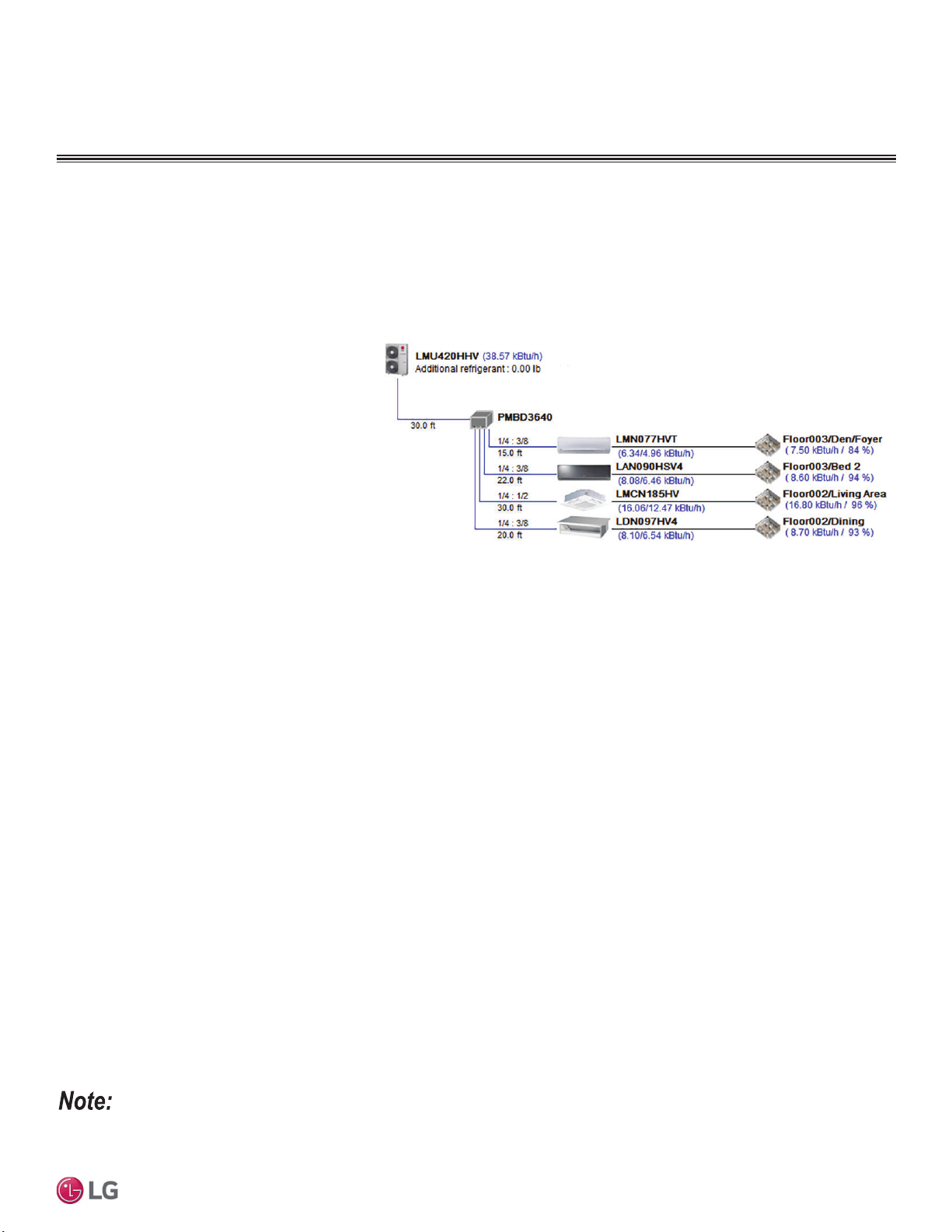
35
General Refrigerant Piping System Information
Due to our policy of continuous product innovation, some specifications may change without notification.
©LG Electronics U.S.A., Inc., Englewood Cliffs, NJ. All rights reserved. “LG” is a registered trademark of LG Corp.
MULTI
F
MAX
MULTI
F
LATS Generates a Complete Project Report
LATS software also generates a report containing project design parameters, cooling and heating design data, system component perfor-
mance, and capacity data. The report includes system combination ratio and refrigerant charge calculations; and provides detailed bill of
material, including outdoor units, indoor units, control devices, accessories, refrigerant pipe sizes segregated by building, by system, by pipe
size, and by pipe segments. LATS can generate an Excel GERP report that can imported into the LG SOPS pricing and ordering system.
Proper Design to Install Procedure
LG encourages a two report design-to-install-proce-
dure. After the design engineer determines building
/ zone loads and other details, the engineer opens
the LATS program and inputs the project’s infor-
mation. When the design is complete, the “Auto
Piping” and “System Check” functions must be used
to verify piping sizes, limitations, and if any design
errors are present. If errors are found, engineers
must adjust the design, and run Auto Piping and
System Check again. When the design passes the
checks, then the engineer prints out a project “Shop
Drawing” (LATS Tree Diagram) and provides it to the
installing contractor. The contractor must follow the
LATS Tree Diagram when building the piping system, but oftentimes the design changes on the building site:
• Architect has changed location and/or purpose of room(s).
• Outdoor unit cannot be placed where originally intended.
• Structural elements prevent routing the piping as planned.
• Air conditioning system conflicts with other building systems (plumbing, gas lines, etc.).
The contractor must mark any deviation from the design on the Shop Drawing, including as-built straight lines and elbows. This “Mark Up”
drawing must be returned to the design engineer or Rep, who must input contractor changes into the LATS file. (Copy the original LATS soft-
ware file, save and rename as a separate file, and modify all piping lengths by double-clicking on each length and editing information.) Like
the shop drawing, the Auto Piping and System Check must also be run on this new “As Built” drawing. The design engineer or Rep must then
provide the final As Built file to the contractor. The Mark Up version must be compared to the As Built version for:
• Differences in pipe diameter(s). If incorrect diameters have been installed, the piping must be changed out. If pipe diameters have changed,
check to see if Y-Branches will also need to be changed.
• Changes to outdoor unit and indoor unit capacities. Capacities changes will impact line length changes.
• Additional refrigerant charge quantity (“Trim Charge”). Trim charge will change if piping lengths and diameters change. The As Built version
must reflect installed piping lengths to ensure correct trim charge.
All documents submitted by the contractor, as well as the Shop Drawing and the As Built Drawing files must be provided for commissioning
purposes. Model and serial numbers for all system components must also be submitted. If the steps previously detailed are not followed,
and all documents are not provided to the commissioning agent, the project runs the risk of not being commissioned and voiding any limited
warranty LG offers on the equipment.
LG AIR CONDITIONER
TECHNICAL SOLUTION (LATS)
Contact your LG representative for the vest software program for your application.
Figure 25: Example of a LATS Tree Diagram.
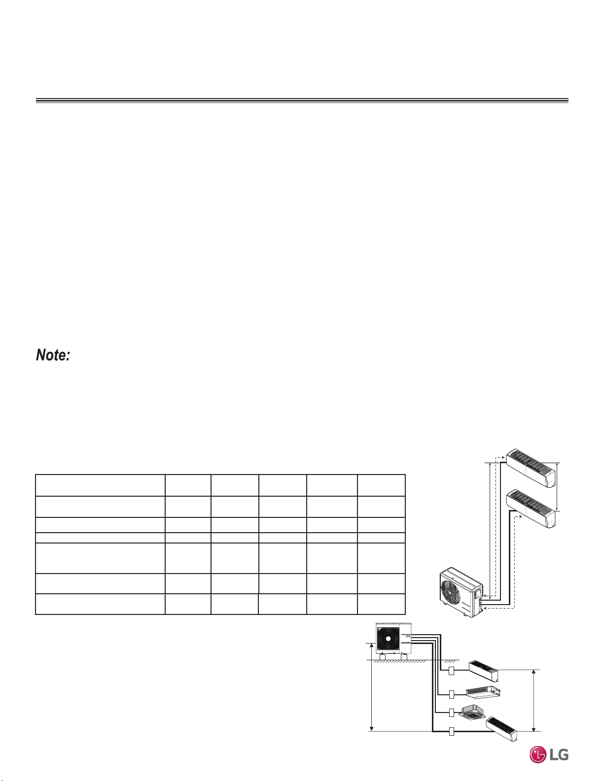
36
MULTI F / MULTI F MAX Outdoor Unit Installation Manual
Due to our policy of continuous product innovation, some specifications may change without notification.
©LG Electronics U.S.A., Inc., Englewood Cliffs, NJ. All rights reserved. “LG” is a registered trademark of LG Corp.
MULTI
F
MAX
MULTI
F
Refrigerant Safety Standards
ASHRAE Standards 15-2010 and 34-2010 address refrigerant safety and the maximum allowable concentration of refrigerant in an occupied
space. Refrigerant will dissipate into the atmosphere, but a certain volume of air is required to safely dissipate the refrigerant. For R410A
refrigerant, the maximum allowable concentration of refrigerant is 26 lbs./1,000 cubic feet (Addendum L modified the RCL to 26) of occupied
spaces. Buildings with 24-hour occupancy allow half of that concentration.
If a VRF system develops a refrigerant leak, the entire refrigerant charge of the system will dump into the area where the leak occurs. To
meet ASHRAE Standards 15 and 34, the smallest room volume on the system must be calculated and compared to the maximum allowable
concentration. If the concentration level is higher than allowed, the following are some design suggestions to eliminate the problem:
• Split dual-frame and triple-frame systems into single-frame systems that have lower refrigerant charges.
• Add transfer grilles in the ceiling or walls of the smaller rooms to increase the volume of the room.
• Remove the smallest space from the system and serve it with a smaller mini-split system.
5()5,*(5$176$)(7<67$1'$5'6
DEVICE CONNECTION LIMITATIONS
h2
h1
A
B
Multi F Outdoor Unit Piping Length and Elevation
Limitations
One of the most critical elements of Multi F and Multi F MAX systems is the refrigerant piping. See below and the following pages for pipe
length limits that must be followed in the design of Multi F and Multi F MAX refrigerant pipe systems.
Figure 26: Multi F Refrigerant Piping System
Limitations (LMU18CHV Example).
Outdoor Unit Model (Btu/h)
LMU18*HV
18,000
LMU240HV
24,000
LMU24CHV
24,000
LMU30CHV
30,000
LMU36CHV
36,000
Max. Total System Piping Length
(ft.)
164
A+B
230.0
A+B+C
246.1
A+B+C
246.1
A+B+C+D
246.1
A+B+C+D
Min. Length for One Branch (ft.) 10 10 10 10 10
Max. Length for One Branch (ft.) 82 82 82 82 82
Max. Elevation Between Each
Indoor Unit and Outdoor Unit
(h1)
49.2 49.2 49.2 49.2 49.2
Max. Elevation Between Indoor
Units (h2)
24.6 24.6 24.6 24.6 24.6
Max. Combination of Indoor
Units
24,000 33,000 33,000 40,000 48,000
Table 12: Multi F Refrigerant Piping System Limitations.
Max. 49.2 feet
Max. 24.6 feet
A
B
C
D
Multi F System Example
Example: LMU36CHV outdoor unit with four (4) indoor units connected.
ODU: Outdoor Unit.
IDU: Indoor Unit.
A, B, C, D: Pipes from Outdoor Unit to Indoor Unit.
Device Connection Limitations
• The minimum number of connected and operating indoor units to Multi F / Multi F MAX systems is two, taking into consideration the
minimum combination ratio.
• The maximum number of indoor units for each Multi F / Multi F MAX heat pump systems is:
LMU18*HV = 2 LMU24*HV = 3 LMU30CHV = 4 LMU36CHV = 4 LMU480HV = 8 LMU540HV = 8 LMU600HV = 8
)RUDOORFDWHGFDSDFLW\LQIRUPDWLRQVHHWKHFRPELQDWLRQWDEOHVLQWKH³0XOWL)0XOWL)0$;&RPELQDWLRQ'DWD0DQXDO´RQZZZOJKYDFFRP)RU
SHUIRUPDQFHGDWDVHH³0XOWL)0XOWL)0$;3HUIRUPDQFH'DWD0DQXDO´RQZZZOJKYDFFRP
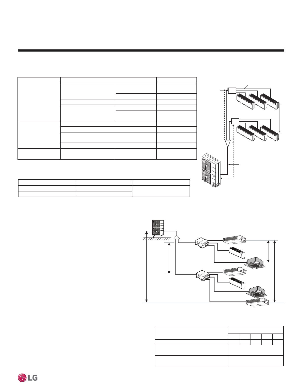
37
General Refrigerant Piping System Information
Due to our policy of continuous product innovation, some specifications may change without notification.
©LG Electronics U.S.A., Inc., Englewood Cliffs, NJ. All rights reserved. “LG” is a registered trademark of LG Corp.
MULTI
F
MAX
MULTI
F
Using Refrigerant Components
Field-supplied elbows are allowed as long as they are designed for
use with R410A refrigerant. The designer, however, must be cau-
tious with the quantity and size of fittings used, and must account
for the additional pressure losses in equivalent pipe length calcula-
tion for each branch. The equivalent pipe length of each elbow must
be added to each pipe segment.
Table 13: Equivalent Piping Length for Elbows, Y-branches, and Branch
Distribution Units.
5()5,*(5$176$)(7<67$1'$5'6
DEVICE CONNECTION LIMITATIONS
Component
Size (Inches)
1/4 3/8 1/2 5/8 3/4
Elbow (ft.) 0.5 0.6 0.7 0.8 1.2
Y-Branch Kit
(ft., Multi F MAX systems only)
1
1.6
Branch Distribution Unit
(ft., Multi F MAX systems only)
8.2
1
.LWFRQWDLQVWZR<EUDQFKHVRQHIRUOLTXLGDQGRQHIRUYDSRU
Example: LMU540HV outdoor unit with seven (7)
indoor units, and two (2) branch distribution units
connected.
ODU: Outdoor Unit.
IDU: Indoor Unit.
BD: Branch Distribution Unit(s).
A: Main Pipe.
B: Branch Pipe (Branch Distribution Unit[s] to Indoor Unit[s]).
B
A
h2 ≤ 49.2 feet
A
h3 ≤ 32.8 feet
h4 ≤ 49.2 feet
h1 ≤ 98.4 feet
BDU Y-Branch
BDU
IDU
A
ODU
IDU
IDU
IDU
IDU
IDU
IDU
B
B
B
B
B
B
Pipe Length
(ELF = Equivalent
Length of pipe in
Feet)
7RWDOSLSLQJOHQJWKȉ$ȉ% IHHW
Main pipe (Outdoor Unit to
Branch Distribution Units:
A)
Minimum for Each
(A) Piping Segment
10 feet
0D[LPXPȉ$ IHHW
7RWDOEUDQFKSLSLQJOHQJWKȉ% IHHW
Branch pipe (Branch
Distribution Units to Indoor
Units: B)
Minimum 10 feet
Maximum IHHW
Elevation Differential
(All Elevation
Limitations are
Measured in Actual
Feet)
If outdoor unit is above or below indoor unit (h1) IHHW
Between the farthest two indoor units (h2) IHHW
Between branch distribution unit and farthest
connected indoor unit(s) (h3)
IHHW
Between branch distribution units (h4) IHHW
Max. Combination of
IDUs
LMU480HV = 65,000 LMU540HV = 73,000 LMU600HV = 81,000
Piping Main Pipe A (inch) Branch Pipe B
Liquid Ø3/8
Depends on the size
of the indoor unit piping
Gas Ø3/4
Multi F MAX System Example with Two Branch Distribution Units
Multi F MAX Outdoor Unit Piping Length and Elevation Limitations
Table 14: Multi F MAX Refrigerant Piping System Limitations.
h1
C
Branch Pipe
Main Pipe
BD Unit
BD Unit
A
B
h2
Figure 27: Multi F MAX Refrigerant Piping
System Limitations.
Table 15: Multi F MAX Piping Sizes.
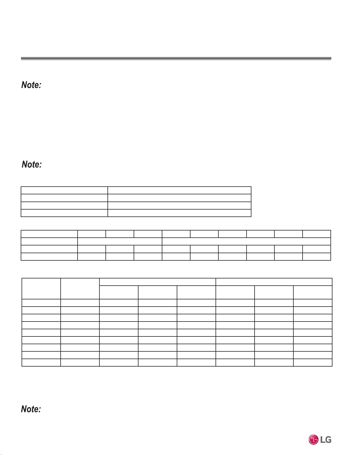
38
MULTI F / MULTI F MAX Outdoor Unit Installation Manual
Due to our policy of continuous product innovation, some specifications may change without notification.
©LG Electronics U.S.A., Inc., Englewood Cliffs, NJ. All rights reserved. “LG” is a registered trademark of LG Corp.
MULTI
F
MAX
MULTI
F
Table 16: ACR Rated Copper Tubing Material.
Table 17: ACR Rated Piping Wall Thicknesses.
1
All dimensions provided are in accordance with ASTM B280 – Standard.
2
Design pressure = 551 psig.
3
The Copper Tube Handbook, 2016, Copper Development Association Inc., 260 Madison Avenue, New York, NY 10016.
Type Seamless Phosphorous Deoxidized
Class UNS C12200 DHP
Straight Lengths H58 Temper
Coils O60 Temper
Table 18: ACR Copper Tubing Dimensions and Physical Characteristics
1-3
.
Selecting Field-Supplied Copper Piping
OD (in) 1/4 3/8 1/2 5/8 3/4 7/8 1-1/8 1-3/8 1-5/8
Material Rigid or Soft ACR Rated for R410A Rigid or Soft ACR Rated for R410A
Min. Bend Radius (in) 0.563 0.9375 1.5 2.25 3.0 3.0 3.5 4.0 4.5
Min. Wall Thickness (in) 0.03 0.03 0.03 0.03 0.03 0.03 0.03 0.04 0.050
Always follow local codes when selecting and installing copper pipe and piping system components.
• Commercially available piping often contains dust and other materials. Always blow it clean with a dry nitrogen.
• Prevent dust, water or other contaminants from entering the piping during installation.
For Multi-Zone Split Systems
Use ACR copper piping rated at the system working pressure (rated for R410A refrigerant).
Approved piping for use with LG HVAC products will be marked “R410 RATED” along the length of the pipe. Piping wall thickness must meet
local code requirements and be approved for a maximum operating pressure of 551 psi. When bending piping, try to keep the number of
bends to a minimum, and use the largest radii possible to reduce the equivalent length of installed piping; also, bending radii greater than ten
(10) piping diameters can minimize pressure drop. Be sure no traps or sags are present.
Always properly support the piping as per the instructions on page 44.
SELECTING COPPER PIPING
Nominal Pipe
Outside
Diameter (in)
Actual Outside
Diameter (in)
Tempered (Hard Drawn) Annealed (Soft)
Nominal Wall
Thickness (in)
Weight (lb/ft)
Cubic ft per
Linear ft
Nominal Wall
Thickness (in)
Weight (lb/ft)
Cubic ft per
Linear ft
1/4 0.250 -- -- -- 0.030 0.081 0.00020
3/8 0.375 0.030 0.126 0.00054 0.032 0.134 0.00053
1/2 0.500 0.035 0.198 0.00101 0.032 0.182 0.00103
5/8 0.625 0.040 0.285 0.00162 0.035 0.251 0.00168
3/4 0.750 0.042 0.362 0.00242 0.042 0.362 0.00242
7/8 0.875 0.045 0.455 0.00336 0.045 0.455 0.00336
1-1/8 1.125 0.050 0.655 0.00573 0.050 0.655 0.00573
1-3/8 1.375 0.055 0.884 0.00875 0.055 0.884 0.00875
1-5/8 1.625 0.060 1.14 0.0124 0.060 1.14 0.0124

39
General Refrigerant Piping System Information
Due to our policy of continuous product innovation, some specifications may change without notification.
©LG Electronics U.S.A., Inc., Englewood Cliffs, NJ. All rights reserved. “LG” is a registered trademark of LG Corp.
MULTI
F
MAX
MULTI
F
Under normal operating conditions, the vapor pipe temperature of a
0XOWL)V\VWHPFDQYDU\DVPXFKDV):LWKWKLVODUJHYDULDQFH
in pipe temperature, the designer must consider pipe expansion and
contraction to avoid pipe and fitting fatigue failures.
Refrigerant pipe along with the insulation jacket form a cohesive
unit that expands and contracts together. During system operation,
thermal heat transfer occurs between the pipe and the surrounding
insulation.
If the pipe is mounted in free air space, no natural restriction to
movement is present if mounting clamps are properly spaced and
installed. When the refrigerant pipe is mounted underground in a
utility duct stacked among other pipes, natural restriction to linear
movement is present. In extreme cases, the restrictive force of
surface friction between insulating jackets could become so great
that natural expansion ceases and the pipe is “fixed” in place. In this
situation, opposing force caused by change in refrigerant fluid/vapor
temperature can lead to pipe/fitting stress failure.
The refrigerant pipe support system must be engineered to allow
free expansion to occur. When a segment of pipe is mounted
between two fixed points, provisions must be provided to allow pipe
expansion to naturally occur. The most common method is the
inclusion of expansion Loop or U-bends mounted in the horizontal
plane. When expansion loops are placed in a vertical riser, the loop
is to be formed in a horizontal fashion resulting in a torsional move-
ment during expansion and contraction. Each segment of pipe has
a natural fixed point where no movement occurs. This fixed point is
located at the center point of the segment assuming the entire pipe
is insulated in a similar fashion. The natural fixed point of the pipe
segment is typically where the expansion Loop or U-bend must be.
Linear pipe expansion can be calculated using the following formula:
1. From the table “Linear Thermal Expansion of Copper Tubing in
Inches,” find the row corresponding with the actual length of the
straight pipe segment.
2. Estimate the minimum and maximum temperature of the pipe.
Typical pipe temperature change ranges: High Pressure Vapor:
DPELHQWWHPSHUDWXUHWR)/RZ3UHVVXUH9DSRUDPELHQWWR
)/LTXLGSLSHDPELHQW))&KRRVHWKHWZRPRVW
extreme. In the column showing the minimum pipe temperature,
look up the anticipated expansion distance. Do the same for the
maximum pipe temperature.
3. Calculate the difference in the two expansion distance values.
The result will be the anticipated change in pipe length.
General Example:
A system is installed and the design shows that there is a 100 foot
straight segment of tubing between a Y-branch and a branch distribu-
tion unit. The system operates 24 hours per day. In heating, this pipe
WUDQVSRUWVKRWJDVYDSRUWRWKHLQGRRUXQLWVDW),QFRROLQJWKH
same tube is a suction line returning refrigerant vapor to the outdoor
XQLWDW)/RRNXSWKHFRSSHUWXELQJH[SDQVLRQDWHDFKWHPSHUD-
ture and calculate the difference.
Vapor Line
7UDQVSRUWLQJ+RW9DSRUIWSLSHDW) LQ
7UDQVSRUWLQJ6XFWLRQ9DSRUIWSLSHDW) LQ
Anticipated Change in Length: 1.40 in. – 0.40 in. = 1.00 in.
Liquid Line
The liquid temperature remains relatively the same temperature; only
the direction of flow will reverse. Therefore, no significant change in
length of the liquid line is anticipated.
When creating an expansion joint, the joint depth must be a
minimum of two times the joint width. Although different types of
expansion arrangements are available, the data for correctly sizing
an expansion loop is provided in the table “Coiled Expansion Loops
and Offsets (Plan View).” Use soft copper with long radius bends
on longer runs or long radius elbows for shorter pipe segments.
Using the anticipated linear expansion (LE) distance calculated, look
up the Expansion Loop or U-bend minimum design dimensions. If
other types of expansion joints are chosen, design per ASTM B-88
Standards.
LE = C x L x (T
r
– T
a
) x 12
LE = Anticipated linear tubing expansion (in.)
& &RQVWDQW)RUFRSSHU [LQLQ)
L = Length of pipe (ft.)
T
r
5HIULJHUDQWSLSHWHPSHUDWXUH)
T
a
$PELHQWDLUWHPSHUDWXUH)
12 = Inches to feet conversion (12 in./ft.)
Copper Expansion and Contraction
COPPER EXPANSION AND
CONTRACTION
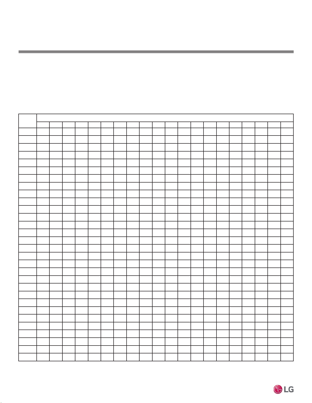
40
MULTI F / MULTI F MAX Outdoor Unit Installation Manual
Due to our policy of continuous product innovation, some specifications may change without notification.
©LG Electronics U.S.A., Inc., Englewood Cliffs, NJ. All rights reserved. “LG” is a registered trademark of LG Corp.
MULTI
F
MAX
MULTI
F
To find the anticipated expansion value:
1. From the table below, find the row corresponding with the actual feet of the straight pipe segment.
2. Estimate the minimum and maximum temperature of the pipe.
3. In the column showing the minimum pipe temperature, look up the anticipated expansion distance corresponding to the segment length.
Do the same for the maximum pipe temperature.
4. Calculate the difference in the two expansion distance values. The result will be the change in pipe length.
Pipe
Length
1
Fluid Temperature °F
35° 40° 45° 50° 55° 60° 65° 70° 75° 80° 85° 90° 95° 100° 105° 110° 115° 120° 125° 130°
10 0.04 0.04 0.05 0.06 0.06 0.07 0.08 0.08 0.09 0.09 0.10 0.10 0.11 0.11 0.11 0.12 0.13 0.14 0.15 0.15
20 0.08 0.08 0.10 0.12 0.13 0.14 0.15 0.16 0.17 0.18 0.19 0.20 0.21 0.22 0.22 0.23 0.26 0.28 0.29 0.30
30 0.12 0.12 0.15 0.18 0.20 0.21 0.23 0.24 0.26 0.27 0.29 0.30 0.32 0.33 0.32 0.35 0.39 0.42 0.44 0.45
40 0.16 0.16 0.20 0.24 0.26 0.28 0.30 0.32 0.34 0.36 0.38 0.40 0.42 0.44 0.43 0.46 0.52 0.56 0.58 0.60
50 0.20 0.20 0.25 0.30 0.33 0.35 0.38 0.40 0.43 0.45 0.48 0.50 0.53 0.55 0.54 0.58 0.65 0.70 0.73 0.75
60 0.24 0.24 0.30 0.36 0.39 0.42 0.45 0.48 0.51 0.54 0.57 0.60 0.63 0.66 0.65 0.69 0.78 0.84 0.87 0.90
70 0.28 0.28 0.35 0.42 0.46 0.49 0.53 0.56 0.60 0.63 0.67 0.70 0.74 0.77 0.76 0.81 0.91 0.98 1.02 1.05
80 0.32 0.32 0.40 0.48 0.52 0.56 0.60 0.64 0.68 0.72 0.76 0.80 0.84 0.88 0.86 0.92 1.04 1.12 1.16 1.20
90 0.36 0.36 0.45 0.54 0.59 0.63 0.68 0.72 0.77 0.81 0.86 0.90 0.95 0.99 0.97 1.04 1.17 1.26 1.31 1.35
100 0.40 0.40 0.50 0.60 0.65 0.70 0.75 0.80 0.85 0.90 0.95 1.00 1.05 1.10 1.08 1.15 1.30 1.40 1.45 1.50
120 0.48 0.48 0.60 0.72 0.78 0.84 0.90 0.96 1.02 1.08 1.14 1.20 1.26 1.32 1.30 1.38 1.56 1.68 1.74 1.80
140 0.56 0.56 0.70 0.84 0.91 0.98 1.05 1.12 1.19 1.26 1.33 1.40 1.47 1.54 1.51 1.61 1.82 1.96 2.03 2.10
160 0.64 0.64 0.80 0.96 1.04 1.12 1.20 1.28 1.36 1.44 1.52 1.60 1.68 1.76 1.73 1.84 2.08 2.24 2.32 2.40
180 0.72 0.72 0.90 1.08 1.17 1.26 1.35 1.44 1.53 1.62 1.71 1.80 1.89 1.98 1.94 2.07 2.34 2.52 2.61 2.70
200 0.80 0.80 1.00 1.20 1.30 1.40 1.50 1.60 1.70 1.80 1.90 2.00 2.10 2.20 2.16 2.30 2.60 2.80 2.90 3.00
220 0.88 0.88 1.10 1.32 1.43 1.54 1.65 1.76 1.87 1.98 2.09 2.20 2.31 2.42 2.38 2.53 2.86 3.08 3.19 3.30
240 0.96 0.96 1.20 1.44 1.56 1.68 1.80 1.92 2.04 2.16 2.28 2.40 2.52 2.64 2.59 2.76 3.12 3.36 3.48 3.60
260 1.04 1.04 1.30 1.56 1.69 1.82 1.95 2.08 2.21 2.34 2.47 2.60 2.73 2.86 2.81 2.99 3.38 3.64
3.77 3.90
280 1.12 1.12 1.40 1.68 1.82 1.96 2.10 2.24 2.38 2.52 2.66 2.80 2.94 3.08 3.02 3.22 3.64 3.92 4.06 4.20
300 1.20 1.20 1.50 1.80 1.95 2.10 2.25 2.40 2.55 2.70 2.85 3.00 3.15 3.30 3.24 3.45 3.90 4.20 4.35 4.50
320 1.28 1.28 1.60 1.92 2.08 2.24 2.40 2.56 2.72 2.88 3.04 3.20 3.36 3.52 3.46 3.68 4.16 4.48 4.64 4.80
340 1.36 1.36 1.70 2.04 2.21 2.38 2.55 2.72 2.89 3.06 3.23 3.40 3.57 3.74 3.67 3.91 4.42 4.76 4.93 5.10
360 1.44 1.44 1.80 2.16 2.34 2.52 2.70 2.88 3.06 3.24 3.42 3.60 3.78 3.96 3.89 4.14 4.68 5.04 5.22 5.40
380 1.52 1.52 1.90 2.28 2.47 2.66 2.85 3.04 3.23 3.42 3.61 3.80 3.99 4.18 4.10 4.37 4.94 5.32 5.51 5.70
400 1.60 1.60 2.00 2.40 2.60 2.80 3.00 3.20 3.40 3.60 3.80 4.00 4.20 4.40 4.32 4.60 5.20 5.60 5.80 6.00
420 1.68 1.68 2.10 2.52 2.73 2.94 3.15 3.36 3.57 3.78 3.99 4.20 4.41 4.62 4.54 4.83 5.46 5.88 6.09 6.30
440 1.76 1.76 2.20 2.64 2.86 3.08 3.30 3.52 3.74 3.96 4.18 4.40 4.62 4.84 4.75 5.06 5.72 6.16 6.38 6.60
460 1.84 1.84 2.30 2.76 2.99 3.22 3.45 3.68 3.91 4.14 4.37 4.60 4.83 5.06 4.97 5.29 5.98 6.44 6.67 6.90
480 1.92 1.92 2.40 2.88 3.12 3.36 3.60 3.84 4.08 4.32 4.56 4.80 5.04 5.28 5.18 5.52 6.24 6.72 6.96 7.20
500 2.00 2.00 2.50 3.00 3.25 3.50 3.75 4.00 4.25 4.50 4.75 5.00 5.25 5.50 5.40 5.75 6.50 7.00 7.25 7.50
1
3LSHOHQJWKEDVHOLQHWHPSHUDWXUH )([SDQVLRQRI&DUERQ&RSSHUDQG6WDLQOHVV6WHHO3LSH7KH(QJLQHHUV7RROER[
www.engineeringtoolbox.com.
Table 19: Linear Thermal Expansion of Copper Tubing in Inches.
COPPER EXPANSION AND
CONTRACTION
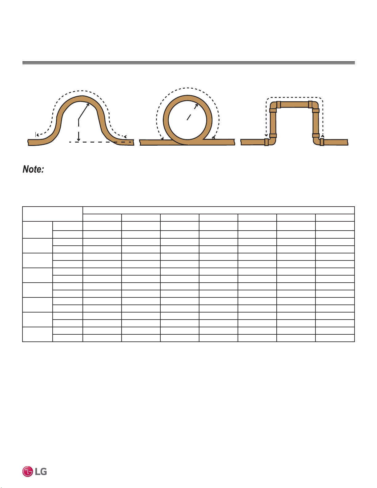
41
General Refrigerant Piping System Information
Due to our policy of continuous product innovation, some specifications may change without notification.
©LG Electronics U.S.A., Inc., Englewood Cliffs, NJ. All rights reserved. “LG” is a registered trademark of LG Corp.
MULTI
F
MAX
MULTI
F
Figure 28: Coiled Expansion Loops and Offsets (Plan View).
Anticipated Linear
Expansion (LE) (in.)
Nominal Tube Size (OD) inches
1/4 3/8 1/2 3/4 1 1-1/4 1-1/2
1/2
R
1
6789111213
L
2
38 44 50 59 67 74 80
1
R
1
9 101113151718
L
2
54 63 70 83 94 104 113
1-1/2
R
1
11 12 14 16 18 20 22
L
2
66 77 86 101 115 127 138
2
R
1
12 14 16 19 21 23 25
L
2
77 89 99 117 133 147 160
2-1/2
R
1
14 16 18 21 24 26 29
L
2
86 99 111 131 149 165 179
3
R
1
15 17 19 23 26 29 31
L
2
94 109 122 143 163 180 196
3-1/2
R
1
16 19 21 25 28 31 34
L
2
102 117 131 155 176 195 212
4
R
1
17 20 22 26 30 33 36
L
2
109 126 140 166 188 208 226
1
R = Centerline Length of Pipe.
2
L = Centerline Minimum Radius (inches).
Table 20: Radii of Coiled Expansion Loops and Developed Lengths of Expansion Offsets.
R
L
L
R
L
Large Tubing U-bend (>3/4 in.) Loop
Small Tubing U-bend (<3/4 in.)
All expansion loops and offsets must be installed in the horizontal plane to prevent the possibility of trapping oil. Loops and offsets in vertical risers
must also be installed in a horizontal plane.
COPPER EXPANSION AND
CONTRACTION
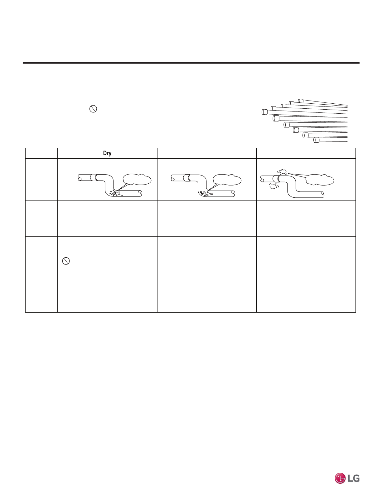
42
MULTI F / MULTI F MAX Outdoor Unit Installation Manual
Due to our policy of continuous product innovation, some specifications may change without notification.
©LG Electronics U.S.A., Inc., Englewood Cliffs, NJ. All rights reserved. “LG” is a registered trademark of LG Corp.
MULTI
F
MAX
MULTI
F
Piping Handling
Pipes used for the refrigerant piping system must include the specified thickness, and the
interior must be clean.
While handling and storing, do not bend or damage the pipes, and take care not to
contaminate the interior with dust, moisture, etc.
Clean Airtight
No moisture should be inside the piping. No dust should be inside the piping. No leaks should occur.
Possible
Problems
- Significant hydrolysis of refrigerant oil.
- Refrigerant oil degradation.
- Poor insulation of the compressor.
- System does not operate properly.
- EEVs, capillary tubes are clogged.
- Refrigerant oil degradation.
- Poor insulation of the compressor.
- System does not operate properly.
- EEVs and capillary tubes become
clogged.
- Refrigerant gas leaks / shortages.
- Refrigerant oil degradation.
- Poor insulation of the compressor.
- System does not operate properly.
Solutions
- Remove moisture from the piping.
- Piping ends should remain capped until
connections are complete.
- Do not install piping on a rainy day.
- Connect piping properly at the unit’s side.
- Remove caps only after the piping is
cut, the burrs are removed, and after
passing the piping through the walls.
- Evacuate system to a maximum of 500
microns and insure the vacuum holds at
that level for 1 hour.
- Remove dust from the piping.
- Piping ends should remain capped until
connections are complete.
- Connect piping properly at the side of
the unit.
- Remove caps only after the piping is cut
and burrs are removed.
- Retain the cap on the piping when
passing it through walls, etc.
- Test system for air tightness.
- Perform brazing procedures that comply
with all applicable standards.
- Perform flaring procedures that comply
with all applicable standards.
- Perform flanging procedures that
comply with all applicable standards.
- Ensure that refrigerant lines are pressure
tested to 550 psig and hold for 24 hours.
Moisture
Dust
Leaks
Keep Pipes Capped While Storing.
Keep refrigerant pipe dry, clean, and airtight.
PIPING HANDLING

43
General Refrigerant Piping System Information
Due to our policy of continuous product innovation, some specifications may change without notification.
©LG Electronics U.S.A., Inc., Englewood Cliffs, NJ. All rights reserved. “LG” is a registered trademark of LG Corp.
MULTI
F
MAX
MULTI
F
REFRIGERANT SYSTEM ENGINEERING
Proper system operation depends on the installer using utmost care while assembling the piping system. The following pages are an over-
view of best practices when installing the refrigerant piping system.
LG Electronics U.S.A.,Inc., is not responsible for any piping calculations, refrigerant leaks, degradation of performance, any other potential problems
or damages caused by the interconnecting piping, their joint connections, isolation valves, or introduced debris inside the piping system.
No Pipe Size Substitutions
Use only the pipe size selected by the LATS HVAC pipe system design software. Using a different size is prohibited and will result in a
system malfunction or failure to work at all.
No In-line Refrigeration Components
Components such as oil traps, solenoid valves, filter-driers, sight glasses, tee fittings, and other after-market accessories are not
permitted on the refrigerant piping system between the outdoor units and the indoor / heat recovery units. LG HVAC systems are provided
with redundant systems that make sure oil is properly returned to the compressor. Sight-glasses and solenoid valves will cause vapor to form
in the liquid stream. Over time, driers will deteriorate and introduce debris into the system. The designer and installer must verify the refriger-
ant piping system is free of traps, sagging pipes, sight glasses, filter driers, etc.
Field-Provided Isolation Ball Valves
LG maintains a neutral position on using isolation valves in LG HVAC refrigerant piping systems. LG does not endorse any manufacturer of
isolation valves. It is recognized that installing isolation valves will simplify future maintenance requirements, and, if used, considerations
must be taken including, but not limited to, the following:
• Pressure drops for any component used, including isolation valves, must be known in equivalent pipe length and calculated into the total
and segment equivalent piping lengths and compared to product design limitations.
• In all cases, materials must be suitable for the application and any applicable codes, including, but not limited to, diameter and wall thick-
ness continuity per ACR standards.
Failure to do so will cause significant performance degradation. Proper leak checks must be performed. Using isolation valves does not
automatically void any LG product warranty, however, a limited warranty will be voided in whole or part must any field supplied accessory fail
in any way that causes product failure.
Using Elbows
Field-supplied elbows are allowed if they are long radius and designed for use with R410A refrigerant. The designer and installer, however,
must be cautious with the quantity and size of fittings used, and must account for the additional pressure losses in equivalent pipe length
calculation for each branch. The equivalent pipe length of each elbow must be added to each pipe segment in the LATS program.
Pipe Bends
When bending soft copper, use long radius bends. Refer to the “Radii of Coiled Expansion Loops and Developed Lengths of Expansion
Offsets” table for minimum radius specifications.
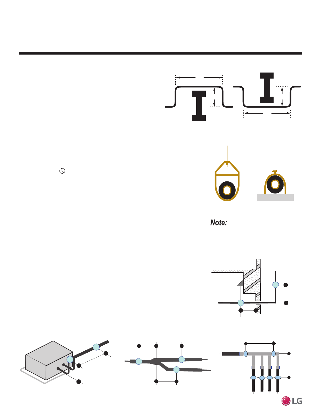
44
MULTI F / MULTI F MAX Outdoor Unit Installation Manual
Due to our policy of continuous product innovation, some specifications may change without notification.
©LG Electronics U.S.A., Inc., Englewood Cliffs, NJ. All rights reserved. “LG” is a registered trademark of LG Corp.
MULTI
F
MAX
MULTI
F
Obstacles
When an obstacle, such as an I-beam or concrete T, is in the path of
the planned refrigerant pipe run, it is best practice to route the pipe
over the obstacle. If adequate space is not available to route the
insulated pipe over the obstacle, then route the pipe under the obsta-
cle. In either case, it is imperative the length of the horizontal section
of pipe above or below the obstacle be a minimum of three (3) times
the longest vertical rise (or fall) at either end of the segment.
Figure 29: Installing Piping Above and Below an Obstacle.
MINIMUM
Above an obstacle
MINIMUM
Below an obstacle
3X
X
3X
X
Pipe Supports
A properly installed pipe system must be adequately supported to avoid pipe sagging. Sag-
ging pipes become oil traps that lead to equipment malfunction.
Pipe supports must
never touch the pipe wall; supports must be installed outside
(around) the primary pipe insulation jacket. Insulate the pipe first because pipe supports
must be installed outside (around) the primary pipe insulation jacket. Clevis hangers must be
used with shields between the hangers and insulation. Field provided pipe supports must be
designed to meet local codes. If allowed by code, use fiber straps or split-ring hangers
suspended from the ceiling on all-thread rods (fiber straps or split ring hangers can be used
as long as they do not compress the pipe insulation). Place a second layer of insulation over
the pipe insulation jacket to prevent chafing and compression of the primary insulation in the
confines of the support clamp.
A properly installed pipe system will have sufficient supports to avoid pipes from sagging
during the life of the system. As necessary, place supports closer for segments where
potential sagging could occur. Maximum spacing of pipe supports must meet local codes.
If local codes do not specify pipe support spacing, pipe must be supported:
• Maximum of five (5) feet on center for straight segments of pipe up to 3/4 inches outside
diameter size.
• Maximum of six (6) feet on center for pipe up to one (1) inch outside diameter size.
• Maximum of eight (8) feet on center for pipe up to two (2) inches outside diameter size.
Wherever the pipe changes direction, place a hanger within twelve (12) inches on one side
and within twelve (12) to nineteen (19) inches of the bend on the other side. Support piping
at indoor units, Y-branch, and Header fittings as shown.
Figure 30: Pipe Hanger Details.
Figure 31: Typical Pipe Support Location—
Change in Pipe Direction.
Figure 32: Pipe Support at Indoor Unit. Figure 33: Pipe Support at Y-branch Fitting.
Figure 34: Pipe Support at Header Fitting.
Max. 12"
~ 12" – 19"
Max. 12" Max. 12"
Max. 12"
Max. 12"
Max. 12"
8VHDORQJVKHHWFXUYHGVKHHWPHWDO
saddles between hanger bracket and insula-
tion to promote linear expansion/contraction.
REFRIGERANT SYSTEM ENGINEERING
~12" – 19"
Maximum 12"
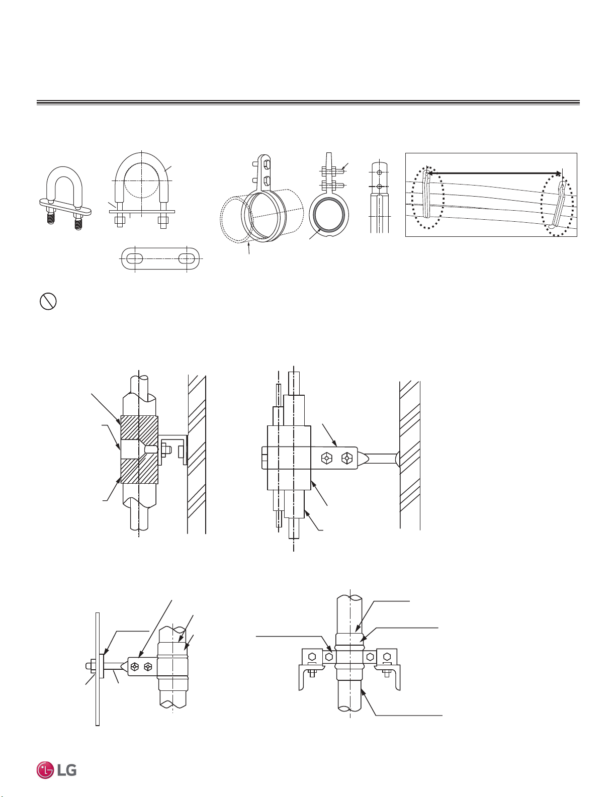
45
General Refrigerant Piping System Information
Due to our policy of continuous product innovation, some specifications may change without notification.
©LG Electronics U.S.A., Inc., Englewood Cliffs, NJ. All rights reserved. “LG” is a registered trademark of LG Corp.
MULTI
F
MAX
MULTI
F
Examples of Supports
Bolt
1.5t
Plate
Insulation
Bolt
PVC
PVC
Figure 35: U-Bolt Support with Insulation. Figure 36: O-Ring Support with Insulation.
To prevent
insulation from
pressing and
lagging, use a cover.
Sheathing
Sheathing
O-Ring
Band
Lags
Do not compress the insulation with the saddle-type support. If the insulation is compressed, it will tear open and allow condensation to
generate during product operation.
Welding
Refrigerant Pipe
Insulated
Support Band
Insulated
Support Band
Down
Stop
Welding
Plate Nut
Hexagonal Nut
O-ring Band
Support at Intervals Between 5 and 6-3/4 Feet
Figure 37: Saddle-Type Support.
Figure 38: U-Bolt Support with an Insulated Pipe. Figure 39: O-Ring Band Support with an Insulated Pipe.
Figure 40: One-Point Down-Stop Support (>441 lbs.).
Figure 41: Two-Point Down-Stop Support.
REFRIGERANT SYSTEM ENGINEERING
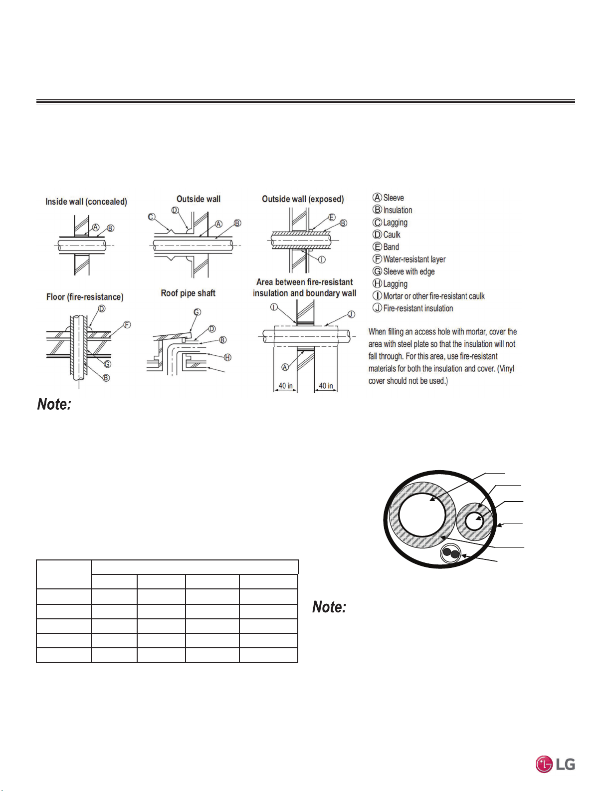
46
MULTI F / MULTI F MAX Outdoor Unit Installation Manual
Due to our policy of continuous product innovation, some specifications may change without notification.
©LG Electronics U.S.A., Inc., Englewood Cliffs, NJ. All rights reserved. “LG” is a registered trademark of LG Corp.
MULTI
F
MAX
MULTI
F
Pipe Sleeves at Penetrations
LG recommends that all pipe penetrations through walls, floors, and pipes buried underground be properly insulated and routed through an
appropriate wall sleeve of sufficient size to prevent compression of refrigerant pipe insulation and promote free movement of the pipe within
the sleeve. Use 4"+ curved sheet metal saddles between the bottom surface of the pipe and the bottom surface of the penetration.
Figure 42: Pipe Sleeve Options.
Diameter of penetrations must be determined by pipe diameter plus the thickness of the insulation.
Underground Refrigerant Piping
Refrigerant pipe installed underground must be routed inside a vapor tight
protective sleeve to prevent insulation deterioration and water infiltration. Re-
frigerant pipe installed inside underground casing must be continuous without
any joints. Underground refrigerant pipe must be located at a level below the
frost line.
Figure 43: Typical Arrangement of Refrigerant Pipe
and Cable(s) in a Utility Conduit.
Table 21: Utility Conduit Sizes.
1
OD pipe diameter in inches; Values in parenthesis () indicate OD of pipe with insulation
jacket.
2
Diameter of pipe with insulation. Thickness of pipe insulation is typical. Actual required
thickness will vary based on surrounding ambient conditions and must be calculated and
VSHFL¿HGE\WKHGHVLJQHQJLQHHU
3
Insulation thickness (value in parenthesis) = 3/8 inch.
4
Insulation thickness (value in parenthesis) = 1 inch.
5
Insulation thickness (value in parenthesis) = 3/4 inch.
Liquid Pipe
1
Vapor Pipe
1
3/8 (2.0
2,5
) 1/2 (2.0
2,5
) 5/8 (2-1/8
2,5
) 3/4 (2-1/4
2,5
)
1/4 (1.0)
3
44 4 4
3/8 (1-1/8)
3
44 4 5
1/2 (1-1/2)
4
55 5 5
5/8 (1-5/8)
4
55 5 5
3/4 (1-3/4)
4
55 5 5
Provide expansion joints in long pipe segments and place in an accessi-
ble conduit box for inspection. Use galvanized curved sheet metal sad-
dles at all mounting points. Pipe must be allowed to move freely linearly.
REFRIGERANT SYSTEM ENGINEERING
Vapor Line
Liquid Line
Min. 18 Gauge
Cable
Power/Communication
Pi
p
e Sleeve
Insulation Material
Insulation
Material
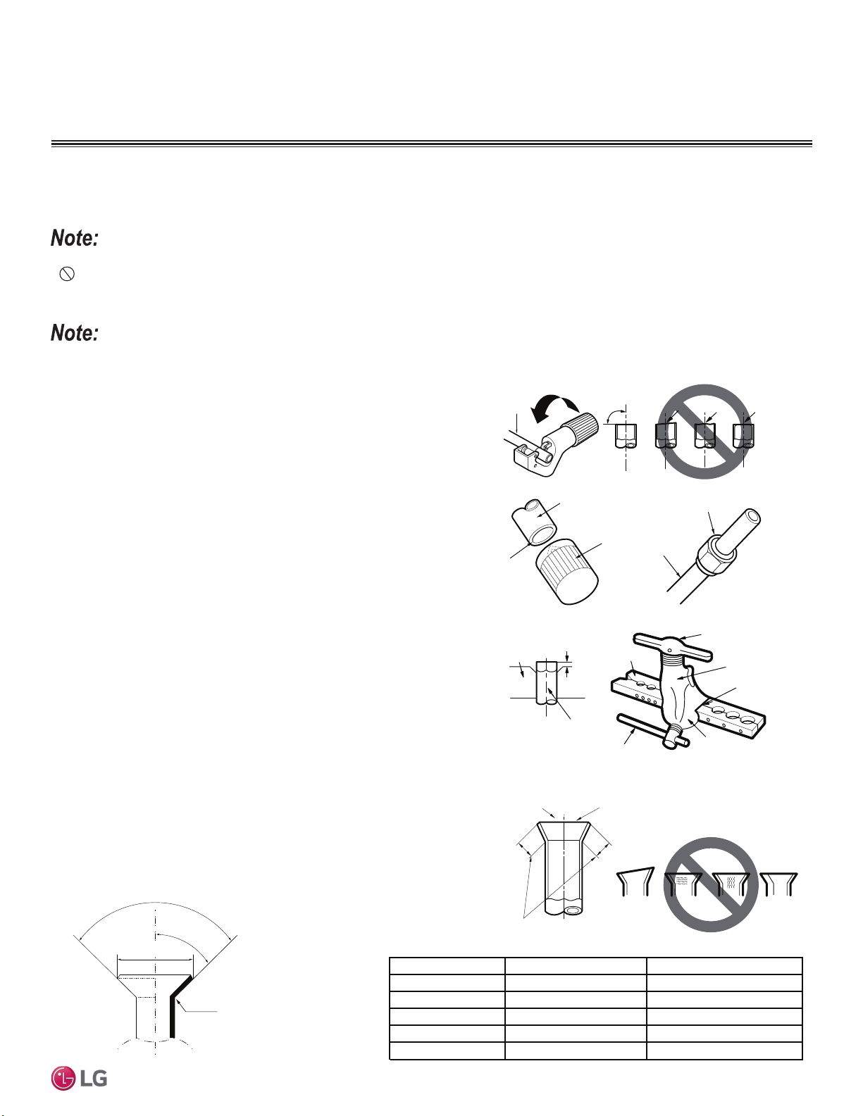
47
General Refrigerant Piping System Information
Due to our policy of continuous product innovation, some specifications may change without notification.
©LG Electronics U.S.A., Inc., Englewood Cliffs, NJ. All rights reserved. “LG” is a registered trademark of LG Corp.
MULTI
F
MAX
MULTI
F
3. Flaring the pipe end.
• Use the proper size flaring tool to finish flared connections as
shown.
• ALWAYS create a 45° flare when working with R410A.
1. Cut the pipe to length.
• Measure the distance between the indoor unit and the outdoor unit.
• Cut the pipes a little longer than measured distance.
2A. Remove the burrs.
• Completely remove all burrs from pipe ends.
• When removing burrs, point the end of the copper pipe down to
avoid introducing foreign materials in the pipe.
2B. Slide the flare nut onto the copper tube.
90°
Slanted Uneven Rough
Pipe
Reamer
Point
down
Flare nut
Copper
tube
Bar
Copper pipe
Clamp handle
Red arrow
Cone
Bar
Slanted
Smooth
Uneven
Thickness
1.
2A. 2B.
3.
4.
4. Carefully inspect the flared pipe end.
• Compare the geometry with the figure to the right
• If the flare is defective, cut it off and re-do procedure.
• If flare looks good, blow the pipe clean with dry nitrogen.
90°
45°
“A”
R=0.4 – 0.8
Dimensions of the Flare.
Pipe Size (in. O.D.) “A” Dimension (mm [in.])
1/2
1/4
5/8
3/8
3/4
Flared Connection Dimensions / Tightening Torque.
Handle
Incorrect Flare
Even Length
Cracked
Yoke
Inside is shiny with no scratches
Surface
Damaged
Copper
tube
Outside Diameter (mm)
6.35
9.52
12.7
15.88
19.05
~ 9.1 (11/32 - 23/64)
~ 13.2 (1/2 - 33/64)
~ 16.6 (41/64 - 21/32)
~ 19.7 (49/64 - 25/32)
-
Flaring Procedure
Flaring and Brazing Procedures
One of the main causes of refrigerant leaks is a defective connection. For LG HVAC systems, the installer needs to know how perform both
flared and brazed connections successfully.
:KHQVHOHFWLQJÀDUH¿WWLQJVDOZD\VXVHD¿WWLQJUDWHGIRUXVHZLWKKLJKSUHVVXUHUHIULJHUDQW5$6HOHFWHG¿WWLQJVPXVWDOVRFRPSO\ZLWKORFDO
state, or federal standards.
• During installation, it is imperative to keep the piping system free of contaminants and debris such as copper burrs, slag, or carbon dust.
•
Do not use kinked pipe caused by excessive bending in one specific area on its length.
FLARING AND BRAZING PROCEDURES
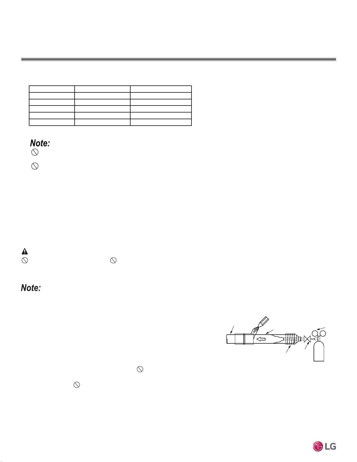
48
MULTI F / MULTI F MAX Outdoor Unit Installation Manual
Due to our policy of continuous product innovation, some specifications may change without notification.
©LG Electronics U.S.A., Inc., Englewood Cliffs, NJ. All rights reserved. “LG” is a registered trademark of LG Corp.
MULTI
F
MAX
MULTI
F
13.0 - 18.0
24.6 - 30.4
39.8 - 47.7
Tightening Torque for Flare Nuts.
Tightening the Flare Nuts
1. When connecting the flare nuts, coat the flare (outside only) with polyvinyl ether (PVE) refrigeration oil only.
2. Initially hand tighten the flare nuts using three (3) or four (4) turns.
3. To finish tightening the flare nuts, use both a torque wrench and a backup wrench.
4. After all the piping has been connected and the caps have been tightened, check for refrigerant gas leaks.
Loosening the Flare Nuts
Always use two (2) wrenches to loosen the flare nuts.
Do not use polyolyester (POE) or any other type of mineral oil as a thread lubricant. These lubricants are not compatible with the PVE oil
used in this system and create oil sludge leading to equipment damage and system malfunction.
Pipe Size (in. O.D.) Tightening Torque (ft-lbs.)
1/2
1/4
5/8
3/8
3/4
Outside Diameter (mm)
6.35
9.52
12.7
15.88
19.05
45.4 - 59.3
71.5 - 87.5
Do not add any contaminants inside the refrigerant piping.
Figure 44: Refrigerant Pipe Brazing.
Pressure-reducing
Valve
Valve
Taping
Nitrogen
Pipe to
be brazed
Refrigerant
Piping
Brazing Procedure
Do not braze in an enclosed location. Do not allow the refrigerant to leak during brazing. Always test for gas leaks before and after brazing.
If the refrigerant combusts, it generates a toxic gas the will cause physical injury or death.
Braze the pipes to the service valve pipe stub of the outdoor unit.
1. All joints are brazed in the field. LG HVAC refrigeration system components contain
very small capillary tubes, small orifices, electronic expansion valves, oil separators,
and heat exchangers that can easily become blocked. Proper system operation de-
pends on the installer using best practices and utmost care while assembling the piping
system.
2. Store pipe stock in a dry place; keep stored pipe capped and clean.
3. Blow clean all pipe sections with dry nitrogen prior to assembly.
4. Use adapters to assemble different sizes of pipe.
5. Always use a non-oxidizing material for brazing.
Do not use flux, soft solder, or anti-oxidant agents. If the proper material is not used,
oxidized film will accumulate and clog or damage the compressors. Flux can harm the copper piping or refrigerant oil.
6. Use a tubing cutter,
do not use a saw to cut pipe. De-bur and clean all cuts before assembly.
7. Brazing joints:
• Use a dry nitrogen purge operating at a minimum pressure of three (3) psig and maintain a steady flow.
• Use a 15% silver phosphorous copper brazing alloy to avoid overheating and produce good flow.
• Protect isolation valves, electronic expansion valves, and other heat-sensitive control components from excessive heat with a wet rag or
heat barrier spray.
WARNING
FLARING AND BRAZING PROCEDURES
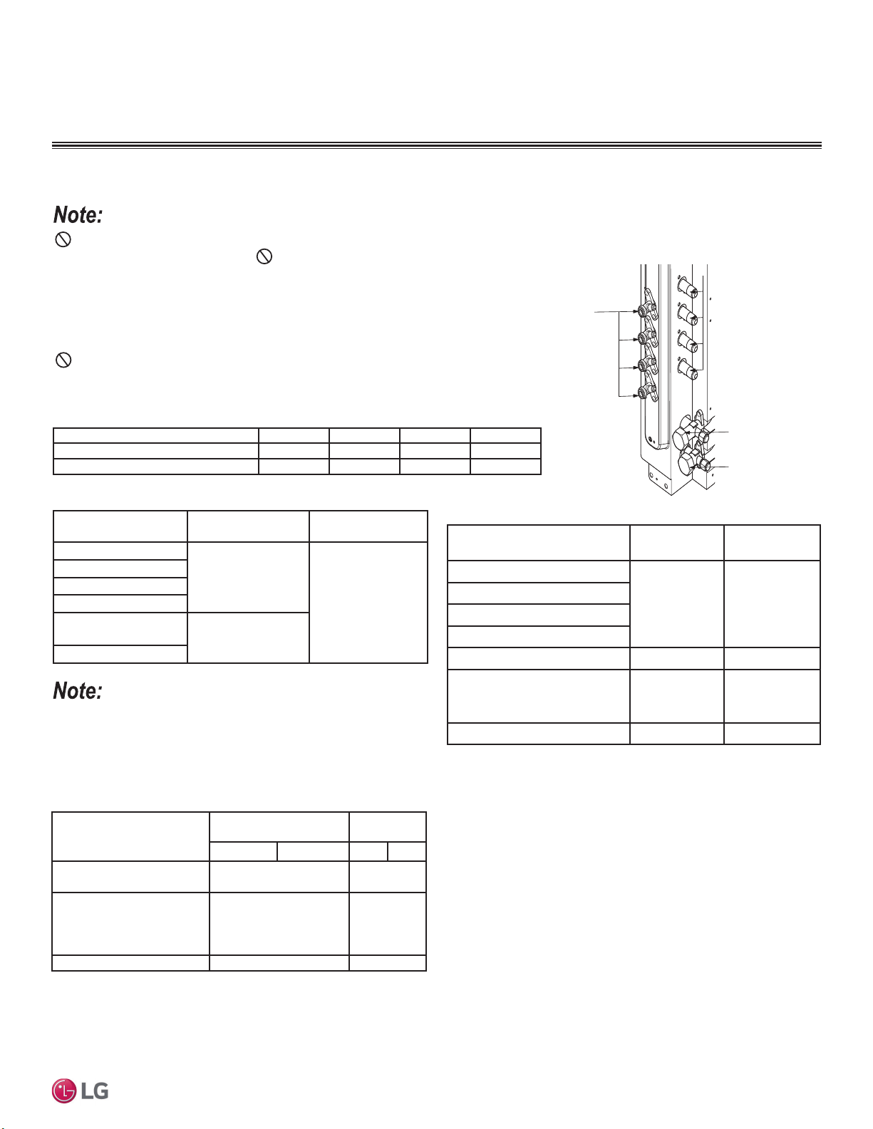
49
Refrigerant Piping System Installation
Due to our policy of continuous product innovation, some specifications may change without notification.
©LG Electronics U.S.A., Inc., Englewood Cliffs, NJ. All rights reserved. “LG” is a registered trademark of LG Corp.
MULTI
F
MAX
MULTI
F
INSTALLING MULTI F SYSTEMS
Connection sockets (included as a factory-supplied accessory with the
indoor units) will need to be used when piping the indoor units to the out-
door unit. See tables above and below for indoor unit piping connection
and connection socket dimensions. If a 36K indoor unit is included, the
connection sockets are included with the Branch Distribution unit.
Table 22: Outdoor Unit Piping Connections.
Figure 45: Multi F Refrigerant Pipe Connections
(LMU36CHV shown as example).
Avoid Pipe Damage
• When routing field-provided piping, avoid damaging the outdoor unit from excessive
vibration.
• Properly insulate the liquid and gas lines separately up to the point of connection at the
unit frame.
• See table below for Multi F outdoor unit connection types.
Main gas
valve
Main liquid
valve
Gas Piping Connections
Liquid
Piping
Connections
A-UNIT
B-UNIT
C-UNIT
D-UNIT
Indoor Unit Capacity
Vapor (in., OD)
Liquid (in.,
OD)
A B A B
18,000 Btu/h: Wall-Mounted
ĺĺ
Ø5/8
ĺ
15,000 Btu/h: Console;
18,000 Btu/h: Low Static
Duct, Four-Way Cassette,
VAHU
ĺ N/A
24,000 Btu/h ĺ N/A
Multi F Outdoor Unit to Indoor Unit Piping Connections
Outdoor Unit Piping Connections LMU18*HV LMU24*HV LMU30CHV LMU36CHV
Liquid Line Connection (in., OD) x Qty. 1/4 x 2 1/4 x 3 1/4 x 4 1/4 x 4
Vapor Line Connection (in., OD) x Qty. 3/8 x 2 3/8 x 3 3/8 x 4 3/8 x 4
Table 23: Indoor Unit Pipe Sizes.
Indoor Unit Capacity
Vapor Line
Piping Size (in., OD)
Liquid Line
Piping Size (in., OD)
7,000 Btu/h
Ø3/8
Ø1/4
9,000 Btu/h
12,000 Btu/h
15,000 Btu/h
15,000 Btu/h: Console;
18,000 Btu/h
Ø1/2
24,000 Btu/h
Table 24: Indoor Unit Piping Connections.
Indoor Unit Capacity
Vapor Line
Conn. (in., OD)
Liquid Line
Conn. (in., OD)
7,000 Btu/h
Ø3/8 Ø1/4
9,000 Btu/h
12,000 Btu/h
15,000 Btu/h
18,000 Btu/h: Wall-Mounted Ø5/8 Ø3/8
15,000 Btu/h: Console;
18,000 Btu/h: Low Static Duct,
Four-Way Cassette, VAHU
Ø1/2 Ø1/4
24,000 Btu/h Ø1/2 Ø1/4
Correctly route the piping so it does not make contact with mounting bolts. Allow room
IRU¿HOGLQVWDOODWLRQ
Table 25: Connection Socket Dimensions.
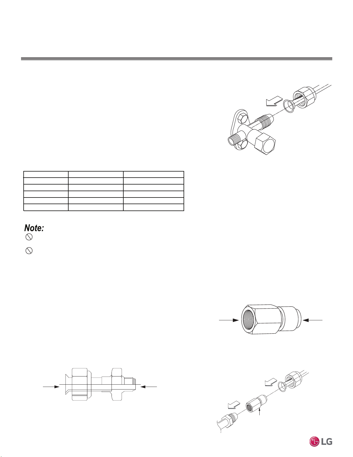
50
MULTI F / MULTI F MAX Outdoor Unit Installation Manual
Due to our policy of continuous product innovation, some specifications may change without notification.
©LG Electronics U.S.A., Inc., Englewood Cliffs, NJ. All rights reserved. “LG” is a registered trademark of LG Corp.
MULTI
F
MAX
MULTI
F
Connection Socket
A
B
Installing Field Piping to the Outdoor Unit Piping Connections
1. Verify the outdoor unit service ports are closed.
2. Remove the caps on the outdoor unit piping connections.
3. Connect the gas piping first to ROOM A, then to ROOM B, then to ROOM C, in that
order. Number of connections will differ depending on outdoor unit.
4. Tighten each gas piping connection individually following the “Tightening the Flare Nuts”
procedure below.
5. Connect the liquid piping first to ROOM A, then to ROOM B, then to ROOM C, in that
order. Number of connections will differ depending on outdoor unit.
6. Tighten each liquid piping connection individually following the “Tightening the Flare
Nuts” procedure below.
Using the Connection Socket
Some indoor units require the use of a connection socket when piping the indoor units
to the outdoor unit. (See previous page for information.) The connection sockets are
included as a factory-supplied accessory with the indoor units. To install:
1. Align the center of the piping sections as seen in the diagrams at right and below.
2. Follow the “Tightening the Flare Nuts” procedure above.
Figure 46: Close Up of the Field Piping to the
Outdoor Unit Piping Connection.
Figure 47: Connection Socket Diagram, External View.
13.0 - 18.0
24.6 - 30.4
39.8 - 47.7
Tightening Torque for Flare Nuts.
Tightening the Flare Nuts
1. When connecting the flare nuts, coat the flare (outside only) with polyvinyl ether (PVE) refrigeration oil only.
2. Initially hand tighten the flare nuts using three (3) or four (4) turns.
3. To finish tightening the flare nuts, use both a torque wrench and a backup wrench.
4. After all the piping has been connected and the caps have been tightened, check for refrigerant gas leaks.
Do not use polyolyester (POE) or any other type of mineral oil as a thread lubricant. These lubricants are not compatible with the PVE oil
used in this system and create oil sludge leading to equipment damage and system malfunction.
Pipe Size (in. O.D.) Tightening Torque (ft-lbs.)
1/2
1/4
5/8
3/8
3/4
Outside Diameter (mm)
6.35
9.52
12.7
15.88
19.05
45.4 - 59.3
71.5 - 87.5
Do not add any contaminants inside the refrigerant piping.
INSTALLING MULTI F SYSTEMS
A
B
Flare
to
Indoor
Unit
Flare
to
Outdoor
Unit
Figure 48: Connection Socket Diagram.
Connection Socket
Figure 49: Performing Connections.
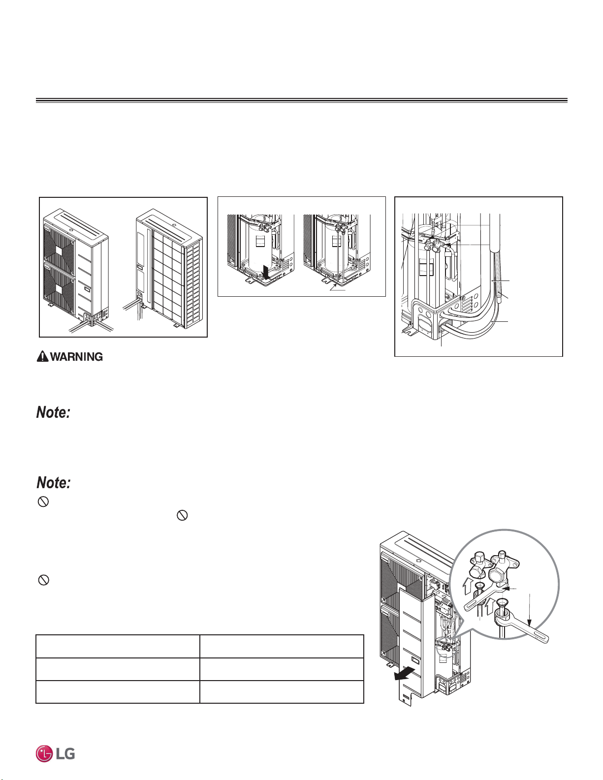
51
Refrigerant Piping System Installation
Due to our policy of continuous product innovation, some specifications may change without notification.
©LG Electronics U.S.A., Inc., Englewood Cliffs, NJ. All rights reserved. “LG” is a registered trademark of LG Corp.
MULTI
F
MAX
MULTI
F
INSTALLING MULTI F MAX SYSTEMS
0XOWL)0$;5HIULJHUDQW3LSLQJ&RQQHFWLRQV3LSLQJ5RXWHV
For Multi F MAX outdoor units, piping can be installed in one of four directions: front, side, back, and down (A). If the downward installation is
chosen, the knockout hole in the base pan must be accessed (B).
Whatever direction is chosen, plug the access holes with field-provided putty or insulation to fill all gaps (C).
,QVHFWVRUVPDOODQLPDOVHQWHULQJWKHRXWGRRUXQLWZLOOFDXVHDVKRUWFLUFXLWLQWKHHOHFWULFDOER[ZKLFKZLOOOHDGWR¿UHHOHFWULFVKRFNSK\VLFDOLQMXU\
or death.
Insects or small animals entering the outdoor unit will cause a short circuit in the electrical box, which will lead to unit failure.
Multi F MAX Outdoor Unit System Piping Connections
Outdoor Unit Piping Connections LMU480HV, LMU540HV, LMU600HV
Liquid Line Connection (in., OD) x Qty. Ø3/8 x 1
Vapor Line Connection (in., OD) x Qty. Ø3/4 x 1
Avoid Pipe Damage
• When routing field-provided piping, avoid damaging the outdoor unit from exces-
sive vibration.
• Properly insulate the liquid and gas lines separately up to the point of connection at
the unit frame.
• See table below for Multi F MAX outdoor unit connection types.
Table 26: Multi F MAX Outdoor Unit Piping Connections.
Figure 50: Multi F MAX Piping Installation.
Correctly route the piping so it does not make contact with mounting bolts. Allow room
IRU¿HOGLQVWDOODWLRQ
Front
Side
Back
Knockout Hole Base Pan
Down
Gas Piping
(Bigger Diameter)
Liquid Piping
(Smaller Diameter)
Putty or Insulation (field-supplied)
Drain Hose
Wire
Connection Pipe
A
B
C
Torque
Wrench
When tightening the
piping connection,
firmly hold the flare nut.
Figure 51: Multi F MAX Outdoor Unit Refrigerant Pipe
Connections.
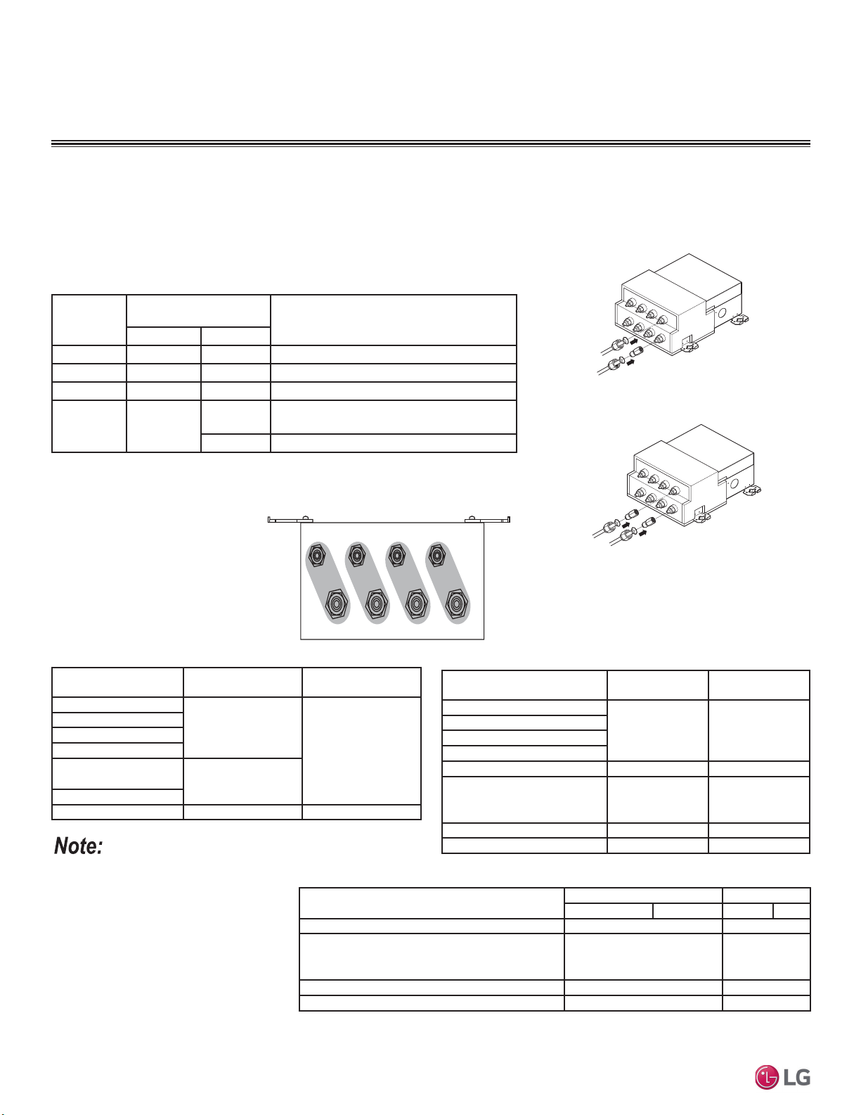
52
MULTI F / MULTI F MAX Outdoor Unit Installation Manual
Due to our policy of continuous product innovation, some specifications may change without notification.
©LG Electronics U.S.A., Inc., Englewood Cliffs, NJ. All rights reserved. “LG” is a registered trademark of LG Corp.
MULTI
F
MAX
MULTI
F
INSTALLING MULTI F MAX SYSTEMS
Branch
Distribution
Unit
Refrigerant Connections
Pipe Size (in.)
Connectible Indoor Unit Capacity
(Btu/h)
Liquid Vapor
PMBD3620 Ø1/4 x 2 Ø3/8 x 2 7,000, 9,000, 12,000, 15,000, 18,000, 24,000
PMBD3630 Ø1/4 x 3 Ø3/8 x 3 7,000, 9,000, 12,000, 15,000, 18,000, 24,000
PMBD3640 Ø1/4 x 4 Ø3/8 x 4 7,000, 9,000, 12,000, 15,000, 18,000, 24,000
PMBD3641 Ø1/4 x 4
Ø3/8 x 3
7,000, 9,000, 12,000, 15,000, 18,000, 24,000
(A, B, C)
Ø1/2 x 1 24,000, 36,000 (D)
Connection sockets (included as a facto-
ry-supplied accessory with the indoor units)
will need to be used when piping the indoor
units to the branch distribution unit. The
connection sockets for 36k indoor units are
factory supplied with the branch distribution
units. See tables above and below for indoor
unit piping connection and connection socket
dimensions. See the follow page for the
connection socket installation procedure.
Branch Distribution to Indoor Unit Piping Connections
• Install indoor unit liquid and vapor refrigerant pipes (and connection wiring) to the appro-
priate branch distribution ports.
• Clearly note on the indoor unit’s refrigerant piping (liquid, vapor) which branch distribution
port it is connected to (A, B, C, D).
Table 27: Branch Distribution Unit Piping Connections.
Table 28: Indoor Unit Pipe Sizes.
Table 29: Indoor Unit Piping Connections.
Figure 52: Branch Distribution Piping
Connections.
ABC D
Indoor Unit
C a p a c i t y
Vapor Line
Piping Size (in., OD)
Liquid Line
Piping Size (in., OD)
7,000 Btu/h
Ø3/8
Ø1/4
9,000 Btu/h
12,000 Btu/h
15,000 Btu/h
15,000 Btu/h: Console;
18,000 Btu/h
Ø1/2
24,000 Btu/h
36,000 Btu/h Ø5/8 Ø3/8
Table 30: Connection Socket Dimensions.
Indoor Unit Capacity
Vapor Line
Conn. (in., OD)
Liquid Line
Conn. (in., OD)
7,000 Btu/h
Ø3/8 Ø1/4
9,000 Btu/h
12,000 Btu/h
15,000 Btu/h
18,000 Btu/h: Wall-Mounted Ø5/8 Ø3/8
15,000 Btu/h: Console;
18,000 Btu/h: Low Static Duct,
Four-Way Cassette, VAHU
Ø1/2 Ø1/4
24,000 Btu/h Ø1/2 Ø1/4
36,000 Btu/h Ø5/8 Ø3/8
Figure 53: Branch Distribution Ports to Indoor
Units -- Side View.
Indoor Unit Capacity
Vapor (in., OD) Liquid (in., OD)
A B A B
18,000 Btu/h: Wall-Mounted ĺĺ ĺ
15,000 Btu/h: Console;
18,000 Btu/h: Low Static Duct, Four-Way
Cassette, VAHU
ĺ N/A
24,000 Btu/h* ĺ N/A
36,000 Btu/h ĺ ĺ
*No socket adapter is required if connected to Port D on the PMBD3641.
Multi F MAX Outdoor Units
(48, 54, 60 kBtu/h)
(For 7~24 kBtu/h Indoor Units)
(Branch Distribution Unit: PMBD3640)
A
ROO
M
B ROOM
C ROOM
D ROOM
A ROOM
B ROOM
C ROOM
D ROOM
(Branch Distribution Unit: PMBD3641)
(Ports A~C only for 7~24 kBtu/h
Indoor Units;
Port D only for 24 or 36 kBtu/h
Indoor Units)
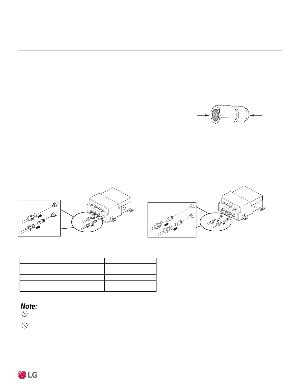
53
Refrigerant Piping System Installation
Due to our policy of continuous product innovation, some specifications may change without notification.
©LG Electronics U.S.A., Inc., Englewood Cliffs, NJ. All rights reserved. “LG” is a registered trademark of LG Corp.
MULTI
F
MAX
MULTI
F
Installing Field Piping to the Branch Distribution Unit Piping Connections
1. Remove any caps, etc., that could be on the branch distribution unit.
2. Tighten each piping connection individually following the “Tightening the Flare Nuts” procedure below.
3. When all piping installation has been completed, perform the triple leak / pressure and evacuation tests (see the Final Installation Proce-
dures Section), verify that the system does not have any leaks, and then fully insulate all joints / connections.
13.0 - 18.0
24.6 - 30.4
39.8 - 47.7
Tightening Torque for Flare Nuts.
Tightening the Flare Nuts
1. When connecting the flare nuts, coat the flare (outside only) with polyvinyl ether (PVE) refrigeration oil only.
2. Initially hand tighten the flare nuts using three (3) or four (4) turns.
3. To finish tightening the flare nuts, use both a torque wrench and a backup wrench.
4. After all the piping has been connected and the caps have been tightened, check for refrigerant gas leaks.
Do not use polyolyester (POE) or any other type of mineral oil as a thread lubricant. These lubricants are not compatible with the PVE oil
used in this system and create oil sludge leading to equipment damage and system malfunction.
Pipe Size (in. O.D.) Tightening Torque (ft-lbs.)
1/2
1/4
5/8
3/8
3/4
Outside Diameter (mm)
6.35
9.52
12.7
15.88
19.05
45.4 - 59.3
71.5 - 87.5
Do not add any contaminants inside the refrigerant piping.
Using the Connection Socket
Some indoor units require the use of a connection socket when piping the indoor
units to the branch distribution unit. (See previous page and below for information.)
The connection sockets are included as a factory-supplied accessory with the indoor
units, or in the case of the 36k indoor unit, it is factory supplied with the branch
distribution units. To install:
1. Remove any caps, etc., that could be on the branch distribution unit.
2. Align the center of the piping sections as seen in the diagram at right.
3. Tighten each piping connection individually following the “Tightening the Flare Nuts” procedure below.
4. When all piping installation has been completed, perform the triple leak / pressure and evacuation tests (see the Final Installation Proce-
dures Section), verify that the system does not have any leaks, and then fully insulate all joints / connections.
INSTALLING MULTI F MAX SYSTEMS
Connection Socket
To Branch
Distribution
Connection
To Flared
End of
Field Piping
Figure 54: Connection Socket Diagram, External View.
Figure 55: Close Up of Branch Distribution to Indoor Unit Piping Connections.
(For 7~24 kBtu/h Indoor Units)
(Branch Distribution Unit: PMBD3640)
A
ROOM
B ROOM
C R
OOM
D ROOM
A
ROOM
B ROOM
C ROOM
D ROOM
(Branch Distribution Unit: PMBD3641)
(Ports A~C only for 7~24 kBtu/h
Indoor Units;
Port D only for 24 or 36 kBtu/h
Indoor Units)
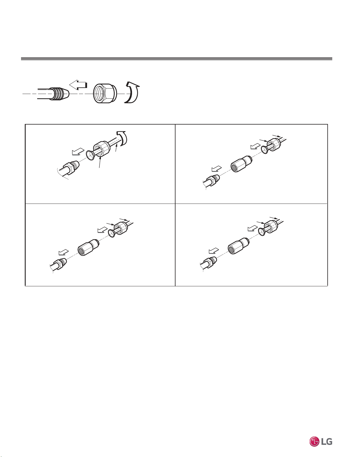
54
MULTI F / MULTI F MAX Outdoor Unit Installation Manual
Due to our policy of continuous product innovation, some specifications may change without notification.
©LG Electronics U.S.A., Inc., Englewood Cliffs, NJ. All rights reserved. “LG” is a registered trademark of LG Corp.
MULTI
F
MAX
MULTI
F
Flare nut
Piping
1. 3/8 in. to 3/8 in.
Connection
2. 3/8 in. to 1/2 in.
Connection
Flare side to
branch distribution unit or outdoor unit
Flare side to indoor unit
Ø3/8 in.
Flare side to indoor
unit
Ø1/2 in.
Connection socket
Flare nut
Piping
Ø3/8 in.
Ø3/8 in.
3. 1/2 in. to 5/8 in.
Connection
Ø5/8 in.
Connection socket
Flare nut
Piping
Ø1/2 in.
4. 1/4 in. to 3/8
Connection
Flare side to indoor
unit
Ø3/8 in.
Connection socket
Flare nut
Piping
Ø1/4 in.
Flare side
to branch
distribution unit or outdoor unit
Flare side to indoor
unit
Flare side
to branch
distribution unit or outdoor unit
Flare side
to branch
distribution unit or outdoor unit
INSTALLING MULTI F MAX SYSTEMS
Figure 56: Socket Connection.
Figure 57: Possible Outdoor Unit or Branch Distribution Unit to Indoor Unit Connections.
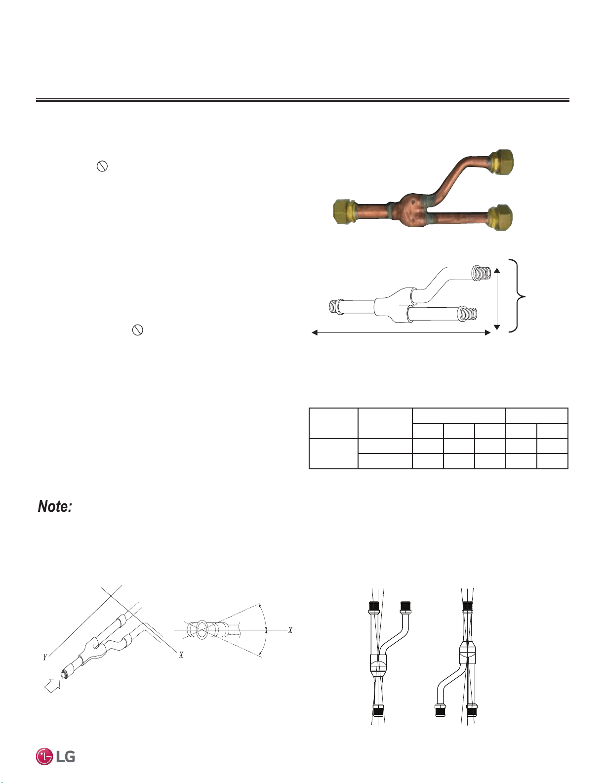
55
Refrigerant Piping System Installation
Due to our policy of continuous product innovation, some specifications may change without notification.
©LG Electronics U.S.A., Inc., Englewood Cliffs, NJ. All rights reserved. “LG” is a registered trademark of LG Corp.
MULTI
F
MAX
MULTI
F
The LG-supplied Y-Branch kit PMBL5620 MUST be used when
installing two (2) branch distribution units in parallel on one (1) Multi
F MAX system.
Field-supplied fittings are not permitted. Each
Y-Branch kit includes two (2) Y-branches (one for the liquid line and
one for the vapor line) and insulation covers.
Y-branches can be installed in horizontal or vertical configurations.
When installed vertically, position the Y-branch so the straight
WKURXJKOHJLVRISOXPE:KHQLQVWDOOHGKRUL]RQWDOO\SRVLWLRQWKH
Y-branch so the take-off leg is level and shares the same horizontal
SODQHDVWKHVWUDLJKWWKURXJKOHJURWDWLRQ
Y-branches must be properly installed following instructions in the
applicable LG manual. Y-branches must always be installed with the
single port facing the outdoor unit and the two-port end facing the
branch distribution units.
Do not install Y-branches backwards
as refrigerant flow cannot make U-turns. The Y-branch kit must be
located at least three (3) feet from the outdoor unit. Provide a min-
imum of 20 inches between a Y-branch and the branch distribution
unit.
When a Y-branch is located in a pipe chase or other concealed
space, access doors must be provided for inspection access.
7KHHTXLYDOHQWSLSHOHQJWKRIHDFK<EUDQFKƍPXVWEHDGGHGWR
the main pipe segment entered into LATS piping design software.
Figure 58: <%UDQFK3RUW,GHQWL¿HU'LDJUDP
Figure 59: Y-Branch Dimensions Diagram.
Figure 60: +RUL]RQWDO&RQ¿JXUDWLRQ(QG9LHZ
Figure 61: <EUDQFK,QVWDOODWLRQ$OLJQPHQW6SHFL¿FDWLRQ
Viewed from A in direction of arrow
Horizontal
plane
Within 5°
A
Within 5°
Vertical Up
Configuration
Within ± 3°Within ± 3°
Vertical Down
Configuration
A
B
X
Y
1
2
3
A = To Outdoor Unit B = To Branch Distribution Unit
1
2
3
Multi F MAX Y-Branch Kit PMBL5620
• Design pressure is 551 psig.
• All dimensions in inches. Tolerance ±1/4 inch.
• Images are not to scale.
Table 31: Y-Branch Connection Diameters.
INSTALLING MULTI F MAX SYSTEMS
Model
Y-Branch
Type
3RUW,GHQWLÀHULQFK Dimensions
123XY
PMBL5620
Liquid 3/8 3/8 3/8 13.80 3.24
Vapor 3/4 3/4 3/4 12.48 3.02
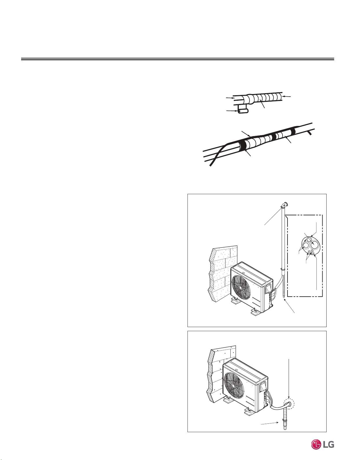
56
MULTI F / MULTI F MAX Outdoor Unit Installation Manual
Due to our policy of continuous product innovation, some specifications may change without notification.
©LG Electronics U.S.A., Inc., Englewood Cliffs, NJ. All rights reserved. “LG” is a registered trademark of LG Corp.
MULTI
F
MAX
MULTI
F
Special Applications
If an additional drain hose is necessary, the end of drain outlet must
be routed above the ground. Secure the drain hose appropriately.
When the Outdoor Unit is Installed Below the Indoor Unit:
1. Use a conduit, piping set cover, or bundle the (separately) insu-
lated refrigerant piping, the drain hose, and the communications /
connection (power) cable together.
2. Make sure to include some slack in the wiring. Wiring must be
installed in an upwards direction to prevent water from accessing
into the control box.
3. Secure the conduit, piping set cover, or bundle along the outside
wall using saddles or a similar type of piping support.
4. Seal any openings in the wall that are around the piping.
Figure 62: Bundling the Connection Components (From Outdoor Unit to
Indoor Unit / Branch Distribution Unit [Multi F MAX systems only]).
Vinyl tape (narrow)
Connection pipe
Connecting cable
Vinyl tape (wide)
Wrap with vinyl tape
Indoor unit pipe
Pipe
When the Outdoor Unit is Installed Above the Indoor Unit:
1. Use a conduit, piping set cover, or bundle the (separately)
insulated refrigerant piping and the communications / connection
(power) cable together up to the outdoor unit service valves.
2. Make sure to include some slack in the wiring. Wiring must be
installed in upwards direction to prevent water from traveling into
the control box.
3. If necessary, secure the conduit, piping set cover, or bundle
along the outside wall using saddles or a similar type of piping
support.
4. Ensure the insulated drain hose from the indoor unit is installed
away from the outdoor unit, and in a downwards direction. If nec-
essary, secure along the outside wall using saddles or a similar
type of support.
5. Seal any openings in the wall that are around the piping.
Figure 63: Special Applications.
BUNDLING AND SPECIAL
APPLICATIONS
Bundling
If a conduit or piping set cover is not used on the connection from
the outdoor unit to the interior, bundle both insulated refrigerant
pipes, the drain hose, and outdoor unit to indoor unit / branch distri-
bution unit communication / connection (power) cable together with
wide vinyl tape.
1. Piping must be fully encased in insulation material: Overlap the
field installation piping insulation material and the indoor unit
piping insulation material.
2. Bind together the two pipes, using vinyl tape. Make sure there
are no gaps during the binding.
3. Be sure the cutting line is placed upward.
4. Wrap the rear piping section with narrow vinyl tape.
5. Continue to wrap the indoor unit pipe as connected to the outdoor
connection pipe.
6. Using a wider vinyl tape, bundle the piping and drain hose
together.
• Tape must be sufficient to cover the piping in order to fit into the
rear piping housing area at the back of the indoor unit.
Insulation
Drain Hose
Piping
Communication
Cables
Power Wiring
Seal the small access hole
in the wall around the piping.
Outdoor Unit Below Indoor Units
Outdoor Unit Above Indoor Units
Seal the small access hole
in the wall around the piping.
Drainage from the Indoor Units
Drainage from the Indoor Units
57
Refrigerant Piping System Installation
Due to our policy of continuous product innovation, some specifications may change without notification.
©LG Electronics U.S.A., Inc., Englewood Cliffs, NJ. All rights reserved. “LG” is a registered trademark of LG Corp.
MULTI
F
MAX
MULTI
F
Condensate Drain Piping
Outdoor unit requires condensate drain piping. Condensate drain pipe must be constructed with materials approved by local code. See pages
21 to 25 for information in reference to outdoor unit placement and condensate drainage.
Drain Leak Test
A leak test must be performed 24 hours after the drainage system has been installed.
CONDENSATE DRAIN PIPING
)RULQGRRUXQLWFRQGHQVDWHGUDLQSLSLQJLQIRUPDWLRQVHHWKH0XOWL)0XOWL)0$;,QGRRU8QLW(QJLQHHULQJ0DQXDORUWKHLQVWDOODWLRQPDQXDOVSHFL¿F
to the indoor unit type.
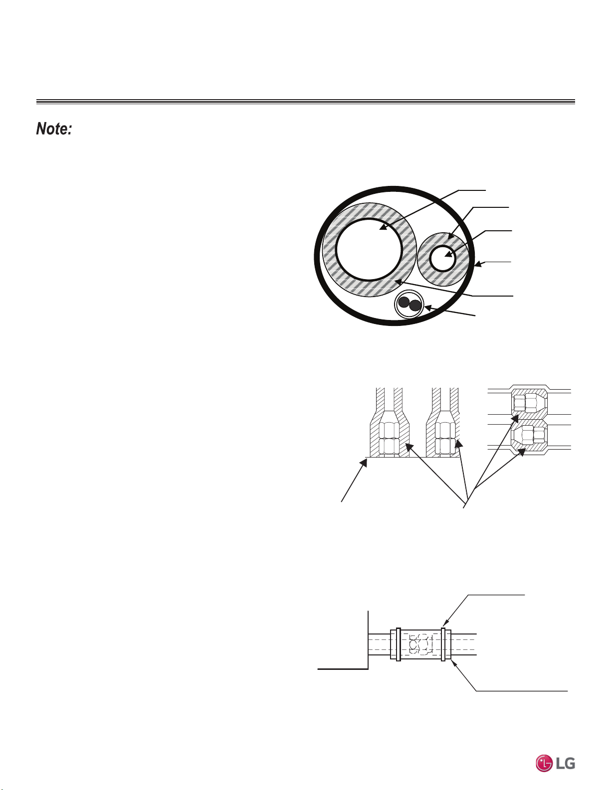
58
MULTI F / MULTI F MAX Outdoor Unit Installation Manual
Due to our policy of continuous product innovation, some specifications may change without notification.
©LG Electronics U.S.A., Inc., Englewood Cliffs, NJ. All rights reserved. “LG” is a registered trademark of LG Corp.
MULTI
F
MAX
MULTI
F
INSULATION
General Piping System Insulation
All refrigerant piping from the outdoor unit to the indoor units /
branch distribution units (Multi F MAX systems only) must be insu-
lated correctly for safety and usage. Y-branch connections, refrig-
erant piping, field-provided isolation ball valves (if present), service
valves, and elbows must be properly and completely insulated using
closed cell pipe insulation (up to the indoor unit piping connections).
To prevent heat loss / heat gain through the refrigerant piping, all
refrigerant piping including liquid lines and vapor lines must be
insulated separately. Insulation must be a minimum 1/2 inches thick,
and thickness will need to be increased based on ambient conditions
and local codes. Table on the next page lists minimum wall thick-
ness requirements for Ethylene Propylene Diene Methylene (EPDM)
insulation.
)RULQIRUPDWLRQUHJDUGLQJLQVXODWLRQIRUXQGHUJURXQGRUSHQHWUDWLRQVLWXDWLRQVVHHWKH³*HQHUDO5HIULJHUDQW3LSLQJ6\VWHP,QIRUPDWLRQ´VHFWLRQ
Vapor Line
Liquid Line
Communication /
Connection (Power) Cable
Pi
p
e Sleeve
Insulation Material
Insulation
Material
Figure 64: Typical Pipe Insulation, Power Wire and Communications
Cable Arrangement
,QVLGHWKHRXWGRRUXQLWPD[LPXPSLSHWHPSHUDWXUHLV)DQG
PLQLPXPSLSHWHPSHUDWXUHLV))RUILHOGLQVXODWLRQRIUHIULJHUDQW
piping between outdoor units and indoor units, consider the following
pipe temperature ranges for an operating heat pump system:
• +HDWLQJPRGHUHIULJHUDQWWHPSHUDWXUHUDQJHV/LTXLG)
+LJK3UHVVXUH9DSRU)
• &RROLQJPRGHUHIULJHUDQWWHPSHUDWXUHUDQJHV/LTXLG)
/RZ3UHVVXUH9DSRU)
All insulation joints must be glued with no air gaps. Insulation
material must fit snugly against the refrigeration pipe with no air
space between it and the pipe. Insulation passing through pipe
hangers, inside conduit, and/or sleeves must not be compressed.
Protect insulation inside hangers and supports with a second layer.
All pipe insulation exposed to the sun and outdoor elements must
be properly protected with PVC, aluminum vapor barrier, or alterna-
tively placed in a weather-resistant enclosure such as a pipe rack
with a top cover; and meet local codes. LG-provided Y-branches
are shipped from the factory with pre-formed peel-and-stick foam
insulation jackets, with a 1.84 lb./ft.
3
density, 1/2 inch thickness, and
meet UL94 MF-1 flammability.
The design engineer must perform calculations to determine if the
factory-supplied insulation jackets are sufficient to meet local codes
and avoid sweating. Add additional insulation if necessary. Check
the fit of the insulation jacket after the Y-branch fitting and all run-out
pipes are installed.
Figure 65: Typical Insulation Butt-Joint at
Indoor Unit Casing.
Figure 66: Typical Refrigerant
Flare Fitting Insulation Detail.
Surface of
Indoor Unit Casing
Field-Provided
Pipe Insulation
Figure 67: Insulating the Shut Off / Isolation Ball Valve (If Present).
Indoor Unit
Insulation (Field Supplied)
Cable Tie, etc.
(Field Supplied)
Refrigerant Piping
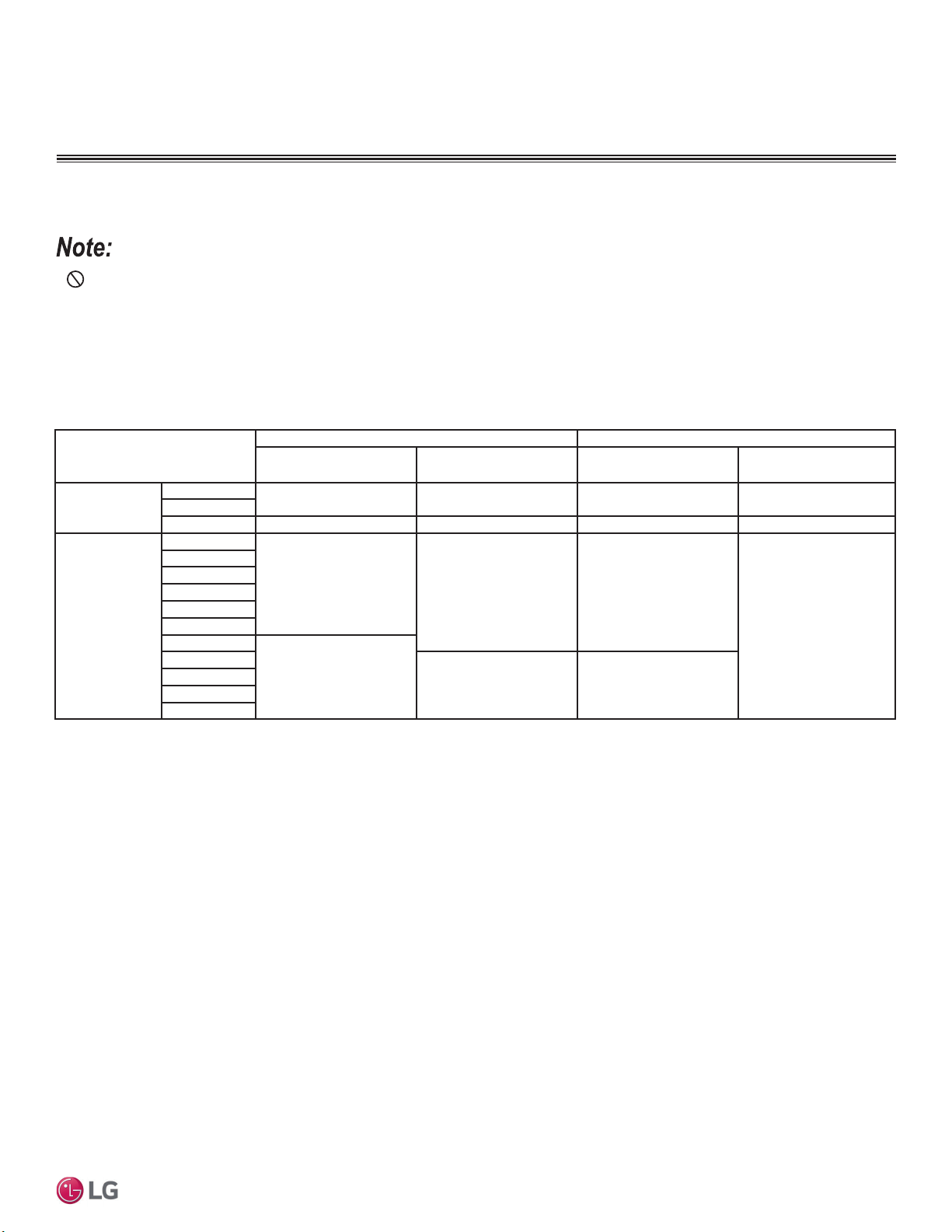
59
Insulation
Due to our policy of continuous product innovation, some specifications may change without notification.
©LG Electronics U.S.A., Inc., Englewood Cliffs, NJ. All rights reserved. “LG” is a registered trademark of LG Corp.
MULTI
F
MAX
MULTI
F
Minimum Refrigerant Pipe Ethylene Propylene Diene Methylene (EPDM)
Insulation Wall Thickness Requirements
• Do not insulate gas and liquid pipes together as this can result in pipe leakage and malfunction due to extreme temperature
fluctuations.
• Always properly insulate the piping. Insufficient insulation will result in condensation, reduced heating/cooling performance, etc. Also, if the
pipes aren’t insulated properly, condensation could potentially cause damage to building finishes. Pay special attention to insulating the
pipes installed in the ceiling plenum.
• Fully insulate the piping connections.
• Follow local codes and the designer’s instructions when selecting ethylene propylene diene methylene (EPDM) insulation wall thickness.
&ODVVLÀFDWLRQ
Air-conditioned location Non-air conditioned location
1. Typical Conditioned
Location
2. Special Conditioned
Location
3. Typical Unconditioned
Location
4. Special Unconditioned
Location
Liquid pipe
ø1/4 inch
>1/2 inch >1/2 inch >1/2 inch >1/2 inch
ø3/8 inch
¡LQFK >1/2 inch >1/2 inch >1/2 inch >1/2 inch
Vapor pipe
ø3/8 inch
>1/2 inch
>3/4 inch >3/4 inch
>1 inch
ø1/2 inch
ø5/8 inch
ø3/4 inch
ø7/8 inch
ø1 inch
ø1-1/8 inches
>3/4 inch
ø1-1/4 inches
>1 inch >1 inch
ø1-3/8 inches
ø1-1/2 inches
ø1-3/4 inches
Table 32: Minimum Refrigerant Pipe EPDM Insulation Wall Thickness Requirements.
1
1. Typical Conditioned Location
$EXLOGLQJSOHQXPRUVSDFHWKDWFRQWDLQVFRQGLWLRQHGDLUWKDWGRHVQRWH[FHHG)'%
2. Special Conditioned Location
1. When the location is air conditioned, but there is severe temperature/humidity difference due to high ceilings.
• Church, auditorium, theater, lobby, etc.
2. When the location is air conditioned, but internal temperature/humidity are high.
• Bathroom, swimming pool, locker room, etc.
3. Typical Unconditioned Location
An unconditioned space inside a building.
4. Special Unconditioned Location: If conditions 1 and 2 below are present.
1. An unconditioned space or plenum of a building.
2. An area where there is an elevated humidity level.
1
The thickness of the above insulation material is based on heat conductivity of 0.61 Btu/in/h/ft
2
)
INSULATION
5. Additional Insulation for Indoor Units Will be Required in Humid Environments.
The air conditioner factory insulation has been tested according to “ISO Conditions with Mist,” and it satisfies the requirements. If the system
KDVEHHQRSHUDWLQJIRUDORQJWLPHLQDKLJKKXPLGLW\HQYLURQPHQWGHZSRLQWWHPSHUDWXUHPRUHWKDQ)FRQGHQVDWHLVOLNHO\WRIRUP,I
WKLVKDSSHQVLQVWDOOLQFKWKLFN(3'0LQVXODWLRQWKDWLVSOHQXPUDWHGZLWKDKHDWUHVLVWDQFHIDFWRURIPRUHWKDQ)
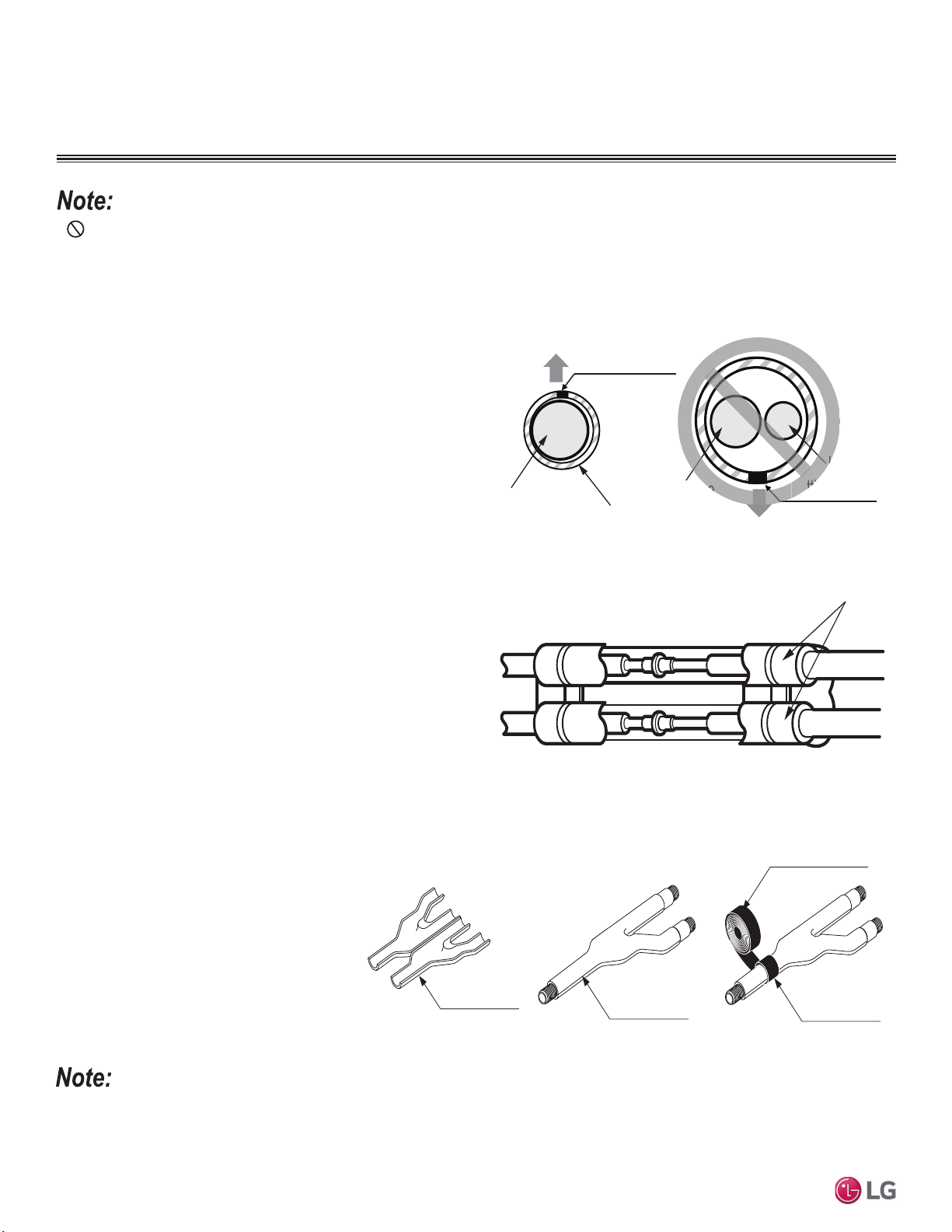
60
MULTI F / MULTI F MAX Outdoor Unit Installation Manual
Due to our policy of continuous product innovation, some specifications may change without notification.
©LG Electronics U.S.A., Inc., Englewood Cliffs, NJ. All rights reserved. “LG” is a registered trademark of LG Corp.
MULTI
F
MAX
MULTI
F
• Do not insulate gas and liquid pipes together as this can result in pipe leakage and malfunction due to extreme temperature
fluctuations.
• Be sure to fully insulate the piping connections.
INSULATION
Insulation material
Figure 68: Correct Cutting Line Placement.
Installing the Insulation
1. Insulation material must be longer than the refrigerant piping.
Each vapor and liquid piping must be insulated separately.
2. Place the closed-cell ethylene propylene diene methylene
(EPDM) insulation material carefully around each refrigerant pipe
so as not to damage it. Be sure the insulation material cutting line
is placed upward.
3. Apply adhesive to both cut surfaces of the insulation and press
together. Allow adhesive to dry so that the bond is secure and
does not come apart.
Figure 69: Piping with Insulation Material.
Gas or Liquid
Pipe (Insulated
Separately)
Liquid Pipe
Cutting Line
Cutting Line
Correct
Incorrect
Insulation
Gas Pipe
L
Cutti
pe
Insulating Piping Joints
1. Push the EPDM insulation from the straight piping surrounding
the joint (elbow, outdoor unit to indoor unit piping connection
point, etc.) as close together as possible.
2. Cut a piece of insulation to fit the joint, overlapping the insulation
on the surrounding piping by at least one (1) inch.
3. Apply adhesive to bond all the ends.
4. Secure by completely wrapping narrow vinyl tape around the
insulation / joint so that there are no gaps.
5. Tape must be sufficient to cover the piping so it can fit into the
rear piping housing area at the back of the indoor unit or branch
distribution unit (Multi F MAX systems only).
Y-Branch Kit Insulation
Each Y-branch kit comes with clam-shell type peel-and-stick insulation jackets molded to fit the Y-branch fittings—one for the liquid line, one
for the vapor line.
• Check the fit of the Y-branch clam-shell
insulation jacket after the Y-branch is
installed.
• Mark all the pipes at the points where the
insulation jacket ends.
• Remove the jacket.
• Install field-provided insulation on the run-
out and main pipes first.
• Peel the adhesive glue protector slip from
the insulation jacket, and install the clam-
shell jacket over the fitting.
Liquid and Gas
Pipe Joints
Y-Branch Kit Insulation
Insulation for
Field-Installed Piping
Field-Supplied Insulation Tape
Figure 70: Y-branch Insulation Detail.
Additional Insulation for Y-Branches Will be Required in Humid Environments.
,IWKHV\VWHPKDVEHHQRSHUDWLQJIRUDORQJWLPHLQDKLJKKXPLGLW\HQYLURQPHQWGHZSRLQWWHPSHUDWXUHPRUHWKDQ)FRQGHQVDWHLVOLNHO\WR
form. If this happens, install 3/8 inch thick ethylene propylene diene methylene (EPDM) insulation that is plenum-rated with a heat-resistance factor
that follows applicable local, state, and federal codes.
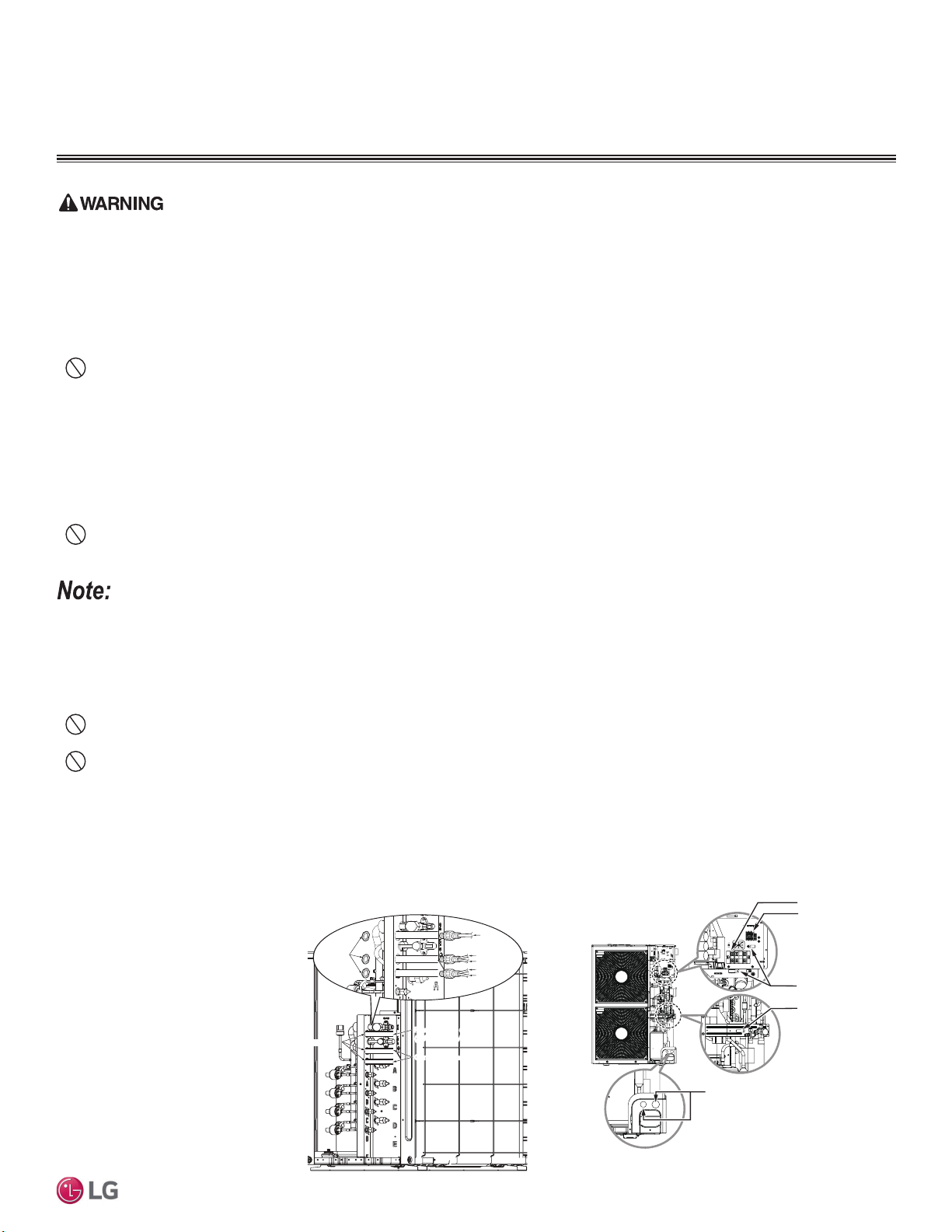
61
Electrical System Installation
Due to our policy of continuous product innovation, some specifications may change without notification.
©LG Electronics U.S.A., Inc., Englewood Cliffs, NJ. All rights reserved. “LG” is a registered trademark of LG Corp.
MULTI
F
MAX
MULTI
F
• All power (line voltage) wiring and communication cable installation must be performed by trained service providers working in accordance
with all local, state, and National Electrical Code (NEC) / UL / ETL federal regulations related to electrical equipment and wiring, and follow-
ing the manufacturer product diagrams, requirements, and instructions in this manual. Electric shock can cause physical injury or death.
• Be sure that main power to the unit is completely off before proceeding. Follow all safety and warning information outlined at the beginning
of this manual. Failure to do so will cause electric shock and bodily injury.
• Install a main shutoff switch or circuit breaker that interrupts all power sources simultaneously (circuit breaker must be resistant to elec-
tromagnetic currents). Be sure that the circuit breaker or some other emergency power cutoff device is in place before any power wiring is
done to the system. Failure to do so will cause bodily injury or death.
•
Never touch any power lines or live cables before all power is cutoff to the system. To do so will cause bodily injury or death.
• Power wiring and communication cable sizes must comply with all applicable federal, state, and local codes. Undersized wiring will lead to
unacceptable voltage at the unit and will cause a fire, which will cause bodily injury or death.
• Properly ground the outdoor unit, indoor units, and branch distribution units. Ground wiring must always be installed by a trained technician.
Ground wiring is required to prevent accidental electrical shock during current leakage, which will cause bodily injury or death.
• Verify that the circuit breaker is set to OFF before installing the wiring system. Electric shock can cause physical injury or death.
• Install appropriately sized breakers / fuses / overcurrent protection switches and wiring in accordance with local, state, and NEC regulations
related to electrical equipment and wiring, and following the instructions in this manual. Generated overcurrent will include some amount of
direct current. Using an oversized breaker or fuse will result in electric shock, physical injury or death.
•
Do not connect ground wire to refrigerant, gas, sewage, or water piping; to lightning rods; to telephone ground wiring; or to the building
plumbing system. Failure to properly provide a NEC-approved earth ground can result in electric shock, fire, physical injury or death.
• Consider ambient conditions (temperature, direct sunlight, inclement weather, etc.) when selecting, installing, and connecting the power wiring.
• Properly ground the outdoor unit, indoor units, and branch distribution units. Ground wiring must always be installed by a trained technician.
Improperly grounded wire can cause communication problems from electrical noise, and motor current leakage.
• Install appropriately sized breakers / fuses / overcurrent protection switches and wiring in accordance with local, state, and NEC regulations
related to electrical equipment and wiring, and following the instructions in this manual. Generated overcurrent will include some amount of
direct current. Using an oversized breaker or fuse will result in equipment malfunction and property damage.
•
Do not connect ground wire to refrigerant, gas, or water piping; to lightning rods; to telephone ground wiring; or to the building plumbing
system. Failure to properly provide a NEC-approved earth ground can result in property damage and equipment malfunction.
•
Do not operate the air conditioning system until the refrigerant piping installation is complete. Operating the system before refrigerant
piping is finalized will damage the compressor.
*HQHUDO,QIRUPDWLRQ
ELECTRICAL
Figure 71: Power Wiring and Communication /
Connection (Power) Cable Paths (LMU18~36CHV;
LMU480, 540HV Example) (Appearances Will Vary).
1. Detach the outdoor unit panel
by loosening the screws.
2. Remove the control cover (if
applicable) by loosening the
screws.
3. When all connections are
complete, re-attach the
cover control to its original
position using the screws,
then re-attach the outdoor
unit panel.
Power Wiring Terminal
Communication / Connection
(Power) Cable Terminal (To
the Indoor Units / Branch
Distribution Units)
Cable Clamp
Cable Clamp
* Make sure rubber bushings are
properly installed in the knock-out holes
after connecting the main power wiring.
/RFDWLRQ$FFHVVLQJWKH3RZHU:LULQJDQG&RPPXQLFDWLRQV&DEOH
Connections
Figure 72: Location of the Power Wiring and Commu-
nication Cable Terminals LMU600HV).
Power supply cabl
(1Ø, 208/230V)
Power Supply Cable
(1Ø, 208/230V)
Connecting cabl
Connecting Cable
Lock nut
(Field Supplied)
Indoor Unit A
Conduit
(Field Supplied)
Indoor Unit B
Indoor Unit C
Indoor Unit D
Conduit
Hole
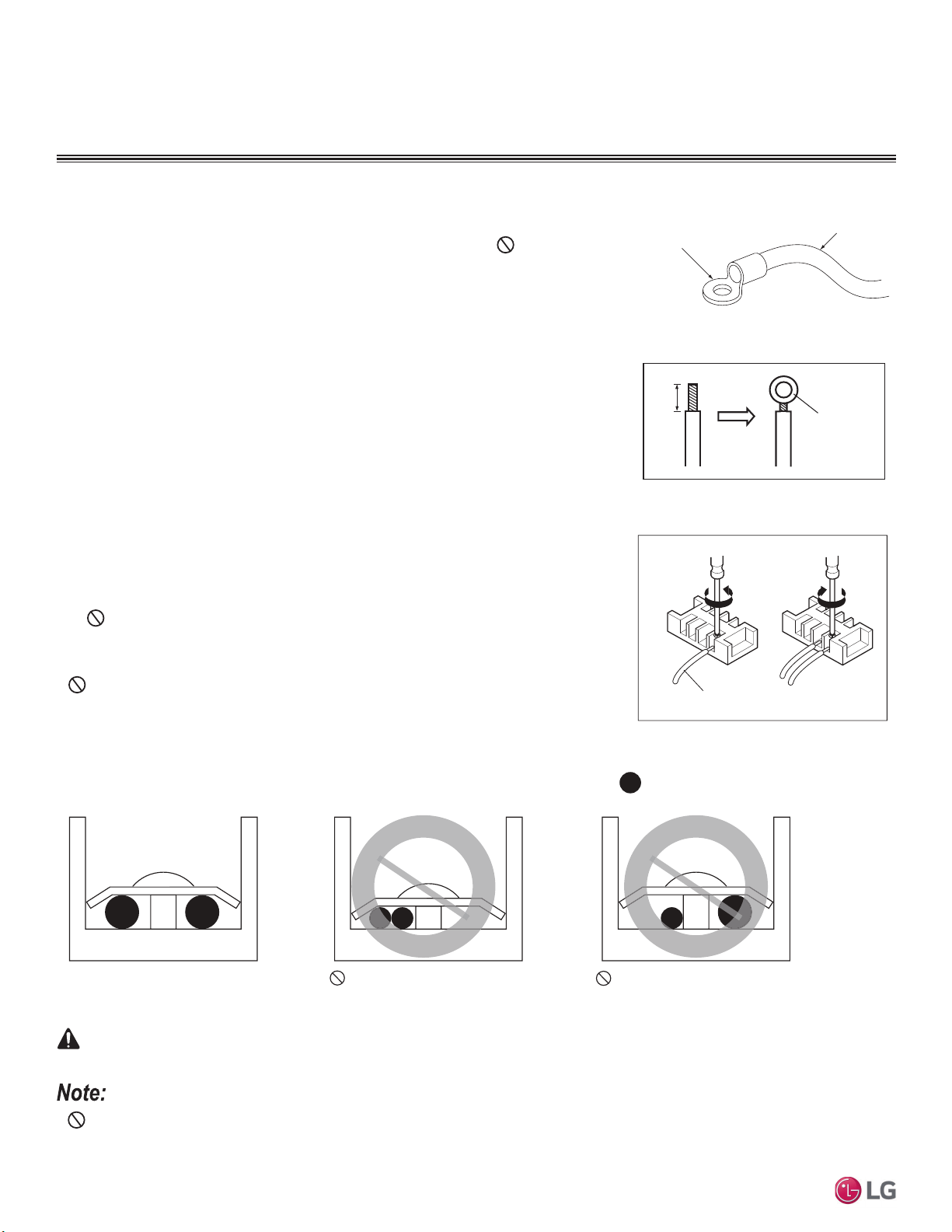
62
MULTI F / MULTI F MAX Outdoor Unit Installation Manual
Due to our policy of continuous product innovation, some specifications may change without notification.
©LG Electronics U.S.A., Inc., Englewood Cliffs, NJ. All rights reserved. “LG” is a registered trademark of LG Corp.
MULTI
F
MAX
MULTI
F
ELECTRICAL
Figure 75: Tightening the Ring Terminal to the
Terminal Plate.
3RZHU:LULQJ&RPPXQLFDWLRQ&DEOH&RQQHFWLRQV
Best practice dictates using solderless ring or fork terminals at all power wiring and com-
munication cable terminations. Use copper bearing ring or fork terminals; do not use
galvanized or nickel plate over steel. Use appropriate crimping tool to attach the ring or fork
terminals at all power wiring and control cable terminations.
To Install a Ring or Fork Terminal:
1. Trim the wiring with wire cutters or pliers, then strip the insulation to expose the strand
wiring to about 3/8 inches.
2. Using a ring terminal fastener or pliers, securely clamp a ring terminal to each stripped
wire end.
Ring Terminal
Wiring / Cable
Figure 73: Close up of a Typical Ring Terminal.
Strip to 3/8"
Ring
Terminal
Connecting Cable
Connecting cable
Loosening the
terminal block
screw
Fastening the
wiring tightly
Figure 74: Adding a Ring Terminal to the
Wiring.
To Connect the Wiring to the Terminals:
1. Remove the JIS terminal screws from the (outdoor unit, branch distribution unit, or indoor
unit) terminal plate with a JIS screwdriver. (See information about LG terminal connec-
tions on the next page.)
2. Position the ring terminal around the terminal, place the terminal screw in the ring, and
tighten to the terminal plate using a JIS screwdriver.
• Firmly attach the wire; secure in a way to prevent external forces from being imparted to
the terminal block.
• Use an appropriately sized JIS screwdriver for tightening the terminals.
•
Do not over tighten the connections; over tightening will damage the terminals.
If ring terminals or fork terminals are not available, then:
•
Do not terminate different gauge wires to the power terminal block. (Slack in the wiring
will generate heat.)
• When terminating wires of the same thickness, follow the instructions demonstrated in the
figures below.
•
Never apply line voltage power to the communications cable terminal block. If contact is made, the PCBs will be damaged.
• Always include some allowance in the wiring length when terminating. Firmly attach the wiring or cable, but provide some slack to facilitate
removing the electrical panels while servicing, and to prevent external forces from damaging the terminal block.
:Copper Wire
Terminate multiple power wires of
the same gauge to both sides.
Do not terminate two wires on
one side.
Do not terminate different gauge
wires to a terminal block.
,ISRZHUZLUHVDUHQRWSURSHUO\WHUPLQDWHGDQG¿UPO\DWWDFKHGWKHUHLVULVNRI¿UHHOHFWULFVKRFNDQGSK\VLFDOLQMXU\RUGHDWK
WARNING
Figure 76: Proper and Improper Power Wiring Connections.
&RQQHFWLRQVDQG6SHFL¿FDWLRQV
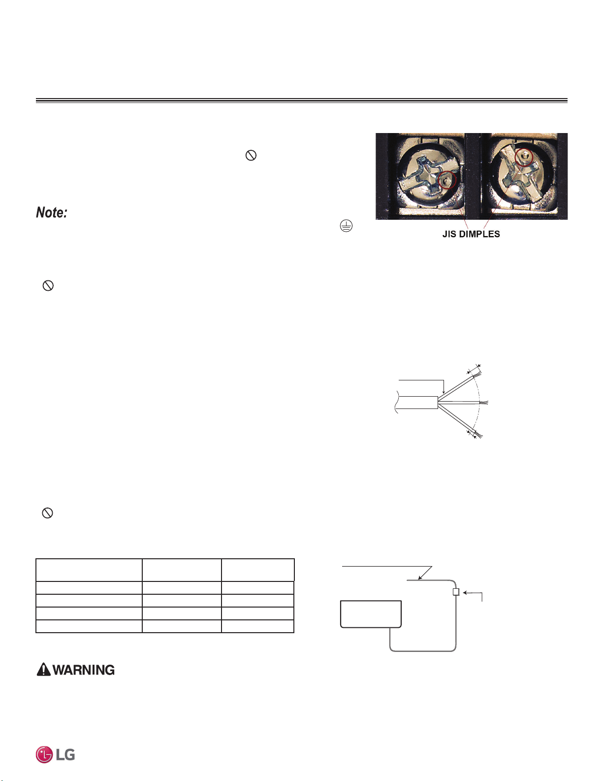
63
Electrical System Installation
Due to our policy of continuous product innovation, some specifications may change without notification.
©LG Electronics U.S.A., Inc., Englewood Cliffs, NJ. All rights reserved. “LG” is a registered trademark of LG Corp.
MULTI
F
MAX
MULTI
F
ELECTRICAL
LG Terminal Connections
LG uses a “JIS” type of screw for all terminals; use a JIS screwdriver to tighten and
loosen these screws and avoid damaging the terminal. Do not over tighten the
connections — over tightening will damage the terminals — but firmly and securely at-
tach the wiring in a way to prevent external forces from being imparted to the terminal
block.
• 7KHWHUPLQDOVODEHOHG³*1'´DUH127JURXQGWHUPLQDOV7KHWHUPLQDOVODEHOHG
ARE ground terminals.
• 3RODULW\PDWWHUV$OZD\VFRQQHFW³$´WR³$´DQG³%´WR³%´
• Always create a wiring diagram that contains the exact sequence in which all the indoor units and branch distribution units (Multi F MAX
systems only) are wired in relation to the outdoor unit.
•
Do not include splices or wire nuts in the communication cable.
Figure 77: JIS Screws.
• Always have a trained service provider properly ground the outdoor unit. If the outdoor unit is not properly grounded, there is a risk of
electric shock, physical injury, or death.
• Provide a circuit breaker between the power source and the outdoor unit. Failure to do so will cause bodily injury or death.
• Multi F and Multi F MAX systems operate at 1Ø, 208-230V, 60Hz, and power is wired
to the outdoor unit only. The outdoor unit will supply power to the indoor units and the
branch distribution units (Multi F MAX systems only) through the communication / con-
nection (power) cable.
• Power supply to the outdoor unit must be selected based on NEC and local codes. Maxi-
mum allowable voltage fluctuation ±10% or nameplate rated value.
• Power wiring to the outdoor unit(s) must be solid or stranded, and must comply with all
local and national electrical codes.
• Properly ground the outdoor unit and indoor unit per NEC and local codes.
• Ground wire must be longer than the common power / communication wires.
• Connect the wiring firmly so the wires cannot be easily pulled out.
• Refer to the inside of the chassis cover or control cover for circuit and terminal block
diagrams.
• Always match color codes of each wire and follow wiring diagram.
•
Do not install power wiring to the outdoor unit and the communication / connection (power) cable to the indoor unit in the same conduit.
Use separate conduits.
3RZHU6XSSO\3RZHU:LULQJ6SHFLILFDWLRQV
Air
Conditioner
Main Power Source
Circuit Breaker
Use a circuit breaker
or time delay fuse
Figure 78: Circuit BreakerTable 33: Circuit Breaker / Fuse Size.
7/16" ± 1/8"
13/16
"
GN/YL
Power Wiring, Ground
to Outdoor Unit
Figure 79: Multi F / Multi F MAX Outdoor Unit
Power Wiring.
&RQQHFWLRQVDQG6SHFL¿FDWLRQV
Outdoor Unit Model Power Source
Fuse or Breaker
Capacity
LMU18*HV, LMU24*HV 1Ø, 208-230V 20A
LMU30CHV, LMU36CHV 1Ø, 208-230V 25A
LMU480HV, LMU540HV 1Ø,208-230V 40A
LMU600HV 1Ø, 208-230V 45A
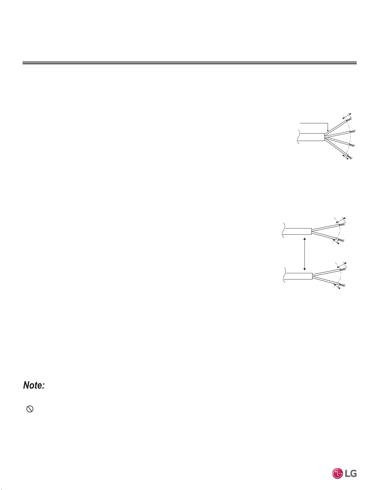
64
MULTI F / MULTI F MAX Outdoor Unit Installation Manual
Due to our policy of continuous product innovation, some specifications may change without notification.
©LG Electronics U.S.A., Inc., Englewood Cliffs, NJ. All rights reserved. “LG” is a registered trademark of LG Corp.
MULTI
F
MAX
MULTI
F
&RPPXQLFDWLRQ&RQQHFWLRQ3RZHU&DEOH6SHFLILFDWLRQV
ELECTRICAL
&RQQHFWLRQVDQG6SHFL¿FDWLRQV
• Multi F Systems:
• Communication / connection (power) cable from the outdoor unit to the indoor unit for
lengths up to 130 feet must use a minimum of 14 AWG, four (4) conductor, stranded,
shielded or unshielded (if shielded, it must be grounded to the chassis of the outdoor
unit only), and must comply with applicable local and national codes.
• When the communication / connection (power) wires between the indoor unit and
outdoor unit is GREATER THAN 130 feet, use:
• A two (2) conductor wire for power (for each indoor unit).
• A two (2) conductor wire for communication / ground (for each indoor unit).
• Separate the power AT LEAST two (2) inches away from the communication /
ground wire (for each indoor unit).
• All wiring is still minimum 14 gauge, stranded, shielded, or unshielded as cited
above (for each indoor unit).
• Multi F MAX Systems:
• All communication / connection (power) cable from the outdoor unit to the branch dis-
tribution unit(s) must be a minimum of 14 AWG, four (4) conductor, stranded, shielded
or unshielded (if shielded, it must be grounded to the chassis of the outdoor unit only),
and must comply with applicable local and national codes.
• Communication / connection (power) cable from the branch distribution unit(s) to
the indoor units for lengths up to 130 feet must use a minimum of 14 AWG, four (4)
conductor, stranded, shielded or unshielded (if shielded, it must be grounded to the
chassis of the outdoor unit only), and must comply with applicable local and national
codes.
• When the communication / connection (power) wires between the branch distribution
unit and indoor unit is GREATER THAN 130 feet, use:
• A two (2) conductor wire for power (for each indoor unit).
• A two (2) conductor wire for communication / ground (for each indoor unit).
• Separate the power AT LEAST two (2) inches away from the communication /
ground wire (for each indoor unit).
• All wiring is still minimum 14 gauge, stranded, shielded, or unshielded as cited above (for each indoor unit).
• Insulation material as required by local code.
• 5DWHGIRUFRQWLQXRXVH[SRVXUHRIWHPSHUDWXUHVXSWR)
• Firmly attach the cable; provide slack but secure in a way to prevent external forces from being imparted on the terminal block.
• Wiring must be completed without splices.
• Use a conduit for the communications / connection (power) cable from the outdoor unit to the indoor units and branch distribution unit(s).
Electrical interference my cause product malfunction.
•
Never ground the shield of the communications cable to the indoor unit frame or other grounded entities of the building. Ground the
communications cable shield only at the outdoor unit. Improperly grounding this cable can cause communications errors.
• The communications / connection (power) cable from the outdoor unit to the indoor units / branch distribution unit(s) must be separated and
isolated from power wiring to the outdoor unit, computers, radio and television broadcasting facilities, as well as medical imaging equip-
ment. Electrical interference my cause product malfunction.
Figure 81: Multi F Outdoor Unit to Indoor Unit, and
Multi F MAX Branch Distribution Unit to Indoor
Unit Wiring Diagram for Wiring Lengths GREATER
THAN 130 Feet.
Two-Conductor
Power Cable
GN/YL
GN/YL = (Ground, Yellow)
Two-Conductor
Communication /
Ground Cable
Separate At Least
Two (2) Inches
13/16"
7/16" ± 1/8"
1(L1)
2(L2)
13/16"
7/16" ± 1/8"
3
Figure 80: Typical Multi F / Multi F MAX Outdoor
and Indoor / Branch Distribution Unit Wiring and
Communications Cable Diagram For Wiring
Lengths Up to 130 Feet.
Power Wiring, Ground,
Communication Cable
From Outdoor Unit
To Indoor Unit or from the
Outdoor Unit to the Branch
Distribution Unit
13/16”
GN/YL
GN/YL = (Ground, Yellow)
7/16" ± 1/8"
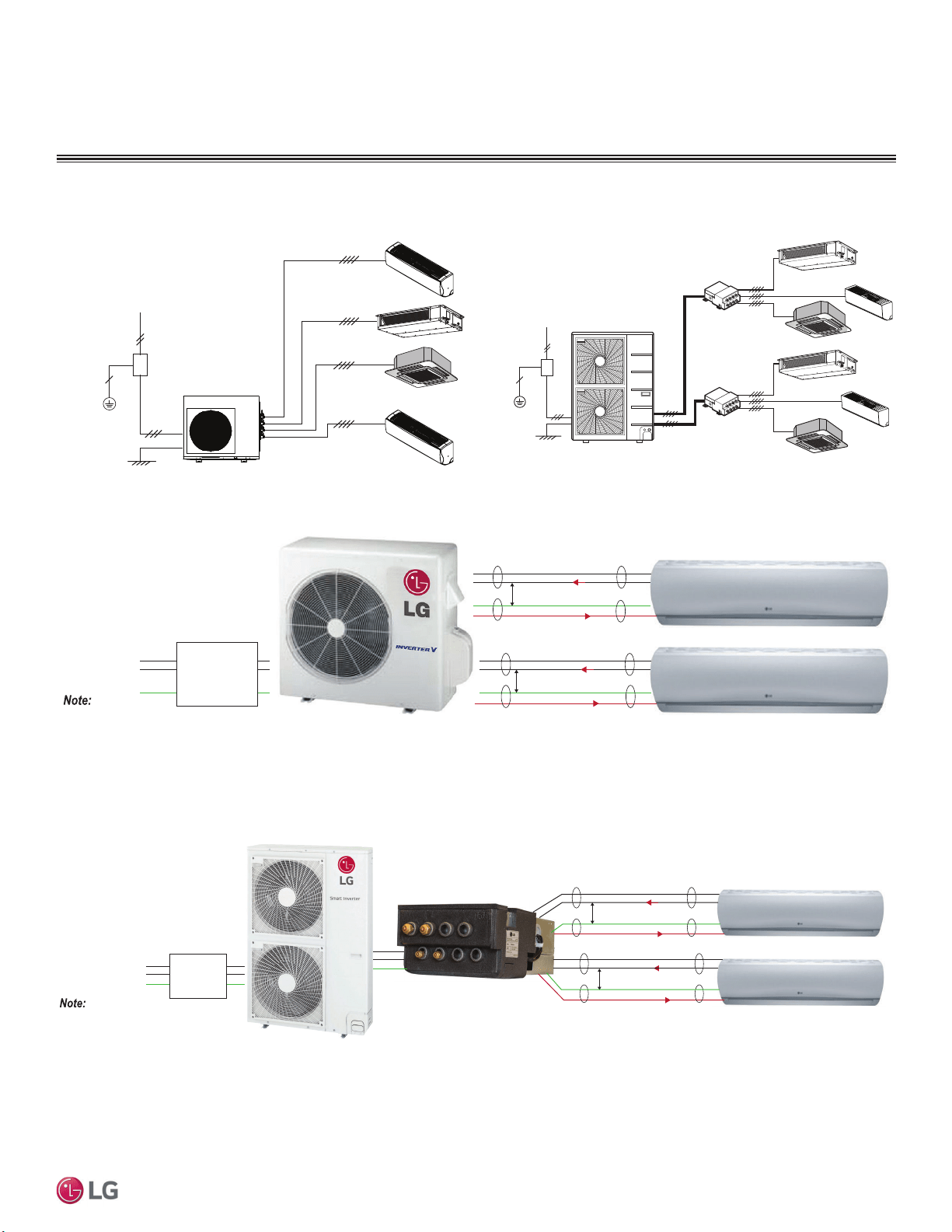
65
Electrical System Installation
Due to our policy of continuous product innovation, some specifications may change without notification.
©LG Electronics U.S.A., Inc., Englewood Cliffs, NJ. All rights reserved. “LG” is a registered trademark of LG Corp.
MULTI
F
MAX
MULTI
F
Figure 82: Typical Multi F System General Power / Communications
System Schematic When Wiring is Less Than 130 Feet.
Figure 83: Typical Multi F MAX System General Power / Communica-
tions System Schematic When Wiring is Less Than 130 Feet.
Power Supply
Circuit Breaker
Indoor Unit
Branch Distribution Unit
Ground Wiring
Outdoor Unit
Branch Distribution Unit
Indoor Units
Power Supply
Circuit Breaker
Ground Wiring
Outdoor Unit
Figure 84: Schematic of a Multi F System When the Wiring is GREATER THAN 130 Feet.
Figure 85: Schematic of a Multi F MAX System When the Wiring is GREATER THAN 130 Feet.
ELECTRICAL
&RQQHFWLRQVDQG6SHFL¿FDWLRQV
Power
Supply
1(L1) (Power, L)
2(L2) (Neutral, N)
G (Ground)
Power Flow: L ĺ N
Diagram is an example of communication and
power cables when the wiring is GREATER THAN
130 feet. Terminals may be labeled differently depending on the model.
Outdoor and Indoor Unit appearances may vary depending on the model.
Communication Flow: Comm ĺ N
3 (Communications)
GREATER THAN 130 feet: Must Separate Communications and Ground (G) Cable
from the Power (1[L1]) and Neutral (2[L2]) Cable at Least Two (2) Inches for Each
Indoor Unit.
At Least Two (2) Inches
3 (Communications)
At Least Two (2) Inches
Power
Supply
1(L1) (Power, L)
2(L2) (Neutral, N)
G (Ground)
Power Flow: L ĺ N
Diagram is an example of communication and power
cables when the wiring is GREATER THAN 130 feet.
Terminals may be labeled differently depending on the model.
Outdoor and Indoor Unit appearances may vary depending on the model.
Communication Flow: Comm ĺ N
3 (Communications)
GREATER THAN 130 feet: Must Separate Communications and Ground (G) Cable from the Power
(1[L1]) and Neutral (2[L2]) Cable at Least Two (2) Inches for Each Indoor Unit
At Least Two (2) Inches
3 (Communications)
At Least Two (2) Inches

66
MULTI F / MULTI F MAX Outdoor Unit Installation Manual
Due to our policy of continuous product innovation, some specifications may change without notification.
©LG Electronics U.S.A., Inc., Englewood Cliffs, NJ. All rights reserved. “LG” is a registered trademark of LG Corp.
MULTI
F
MAX
MULTI
F
ELECTRICAL
• All field-supplied wiring, components, and materials must comply with all applicable national, state, and local codes and requirements.
Improper wiring will result in fire, electric shock, physical injury or death.
• Ground wiring is required to prevent accidental electrical shock during current leakage, communication problems from electrical noise, and
motor current leakage.
Do not connect the ground line to the pipes. There is a risk of fire, electric shock, explosion, physical injury or
death.
• Install a main shutoff switch or circuit breaker that interrupts all power sources simultaneously. There is a risk of fire, electric shock, explo-
sion, physical injury or death.
• All field-supplied wiring, components, and materials must comply with all applicable national, state, and local codes and requirements.
Failure to install proper electrical components can result in property damage and equipment malfunction.
• Ground wiring is required to prevent communication problems from electrical noise, and motor current leakage. Failure to provide proper
ground wiring can result in property damage and equipment malfunction.
• Install a main shutoff switch or circuit breaker that interrupts all power sources simultaneously. Failure to install proper electric components
can result in property damage and equipment malfunction.
• Maintain polarity throughout the communication network. The system will malfunction if not properly wired.
,QVWDOODWLRQ
Figure 86: Multi F LMU180HV and LMU18CHV System Power Wiring and Communications Cable.
Outdoor Unit
(L)L1 N(L2) 3(A) 3(B)
Outdoor Unit Terminal Block
L1
L1
L2
L2
G
Power Supply
Main Switch
Circuit Breaker
Fuse
Three-wire Power Wiring
(Including Ground)
COMMUNICATION CABLE
POWER WIRING
1(L1) 2(L2)
Indoor Unit Terminal Block
Unit A Unit B
3
1(L1) 2(L2) 3
Indoor Unit Terminal Block
G
1(L1)
or L(L1)
N(L2)
or 2(L2)
GG
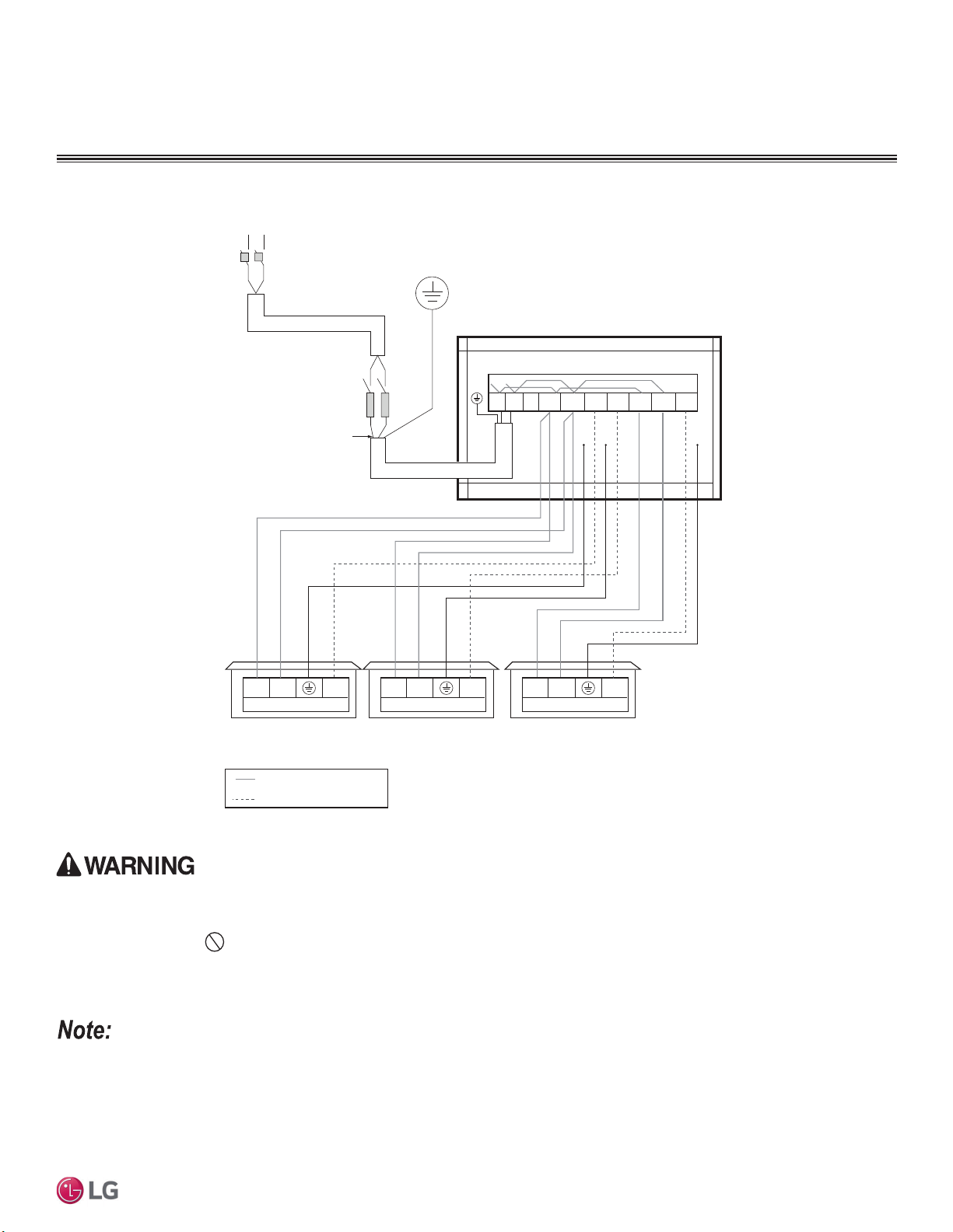
67
Electrical System Installation
Due to our policy of continuous product innovation, some specifications may change without notification.
©LG Electronics U.S.A., Inc., Englewood Cliffs, NJ. All rights reserved. “LG” is a registered trademark of LG Corp.
MULTI
F
MAX
MULTI
F
Figure 87: Multi F LMU240HV and LMU24CHV System Power Wiring and Communications Cable.
• All field-supplied wiring, components, and materials must comply with all applicable national, state, and local codes and requirements.
Improper wiring will result in fire, electric shock, physical injury or death.
• Ground wiring is required to prevent accidental electrical shock during current leakage, communication problems from electrical noise, and
motor current leakage.
Do not connect the ground line to the pipes. There is a risk of fire, electric shock, explosion, physical injury or
death.
• Install a main shutoff switch or circuit breaker that interrupts all power sources simultaneously. There is a risk of fire, electric shock, explo-
sion, physical injury or death.
• All field-supplied wiring, components, and materials must comply with all applicable national, state, and local codes and requirements.
Failure to install proper electrical components can result in property damage and equipment malfunction.
• Ground wiring is required to prevent communication problems from electrical noise, and motor current leakage. Failure to provide proper
ground wiring can result in property damage and equipment malfunction.
• Install a main shutoff switch or circuit breaker that interrupts all power sources simultaneously. Failure to install proper electric components
can result in property damage and equipment malfunction.
• Maintain polarity throughout the communication network. The system will malfunction if not properly wired.
ELECTRICAL
,QVWDOODWLRQ
Outdoor Unit
3(A) 3(C)3(B)
Outdoor Unit Terminal Block
L1
L1
L2
L2
G
Power Supply
Main Switch
Circuit Breaker
Fuse
Three-wire Power Wiring
(Including Ground)
COMMUNICATIONS CABLE
POWER WIRING
1(L1) 2(L2)
Indoor Unit Terminal Block
Unit A Unit B Unit C
3
1(L1) 2(L2) 3 1(L1) 2(L2) 3
Indoor Unit Terminal Block Indoor Unit Terminal Block
G
G
G
GG
(L)L1 N(L2)
1(L1)
or L(L1)
N(L2)
or 2(L2)
1(L1)
or L(L1)
N(L2)
or 2(L2)
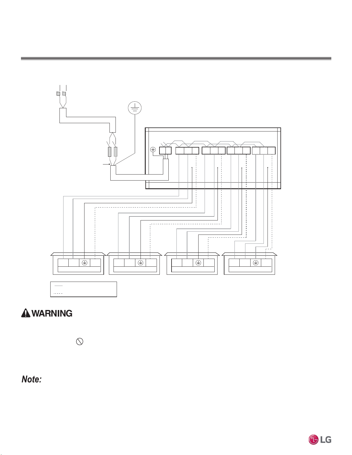
68
MULTI F / MULTI F MAX Outdoor Unit Installation Manual
Due to our policy of continuous product innovation, some specifications may change without notification.
©LG Electronics U.S.A., Inc., Englewood Cliffs, NJ. All rights reserved. “LG” is a registered trademark of LG Corp.
MULTI
F
MAX
MULTI
F
Figure 88: Multi F LMU30CHV and LMU36CHV System Power Wiring and Communications Cable.
• All field-supplied wiring, components, and materials must comply with all applicable national, state, and local codes and requirements.
Improper wiring will result in fire, electric shock, physical injury or death.
• Ground wiring is required to prevent accidental electrical shock during current leakage, communication problems from electrical noise, and
motor current leakage.
Do not connect the ground line to the pipes. There is a risk of fire, electric shock, explosion, physical injury or
death.
• Install a main shutoff switch or circuit breaker that interrupts all power sources simultaneously. There is a risk of fire, electric shock, explo-
sion, physical injury or death.
• All field-supplied wiring, components, and materials must comply with all applicable national, state, and local codes and requirements.
Failure to install proper electrical components can result in property damage and equipment malfunction.
• Ground wiring is required to prevent communication problems from electrical noise, and motor current leakage. Failure to provide proper
ground wiring can result in property damage and equipment malfunction.
• Install a main shutoff switch or circuit breaker that interrupts all power sources simultaneously. Failure to install proper electric components
can result in property damage and equipment malfunction.
• Maintain polarity throughout the communication network. The system will malfunction if not properly wired.
ELECTRICAL
,QVWDOODWLRQ
Outdoor Unit
L1 L2 1(L1) 2(L2) 3(A)
3(C)
3(D)
3(B)
Outdoor Unit Terminal Block
L1
L1
L2
L2
G
Power Supply
Main Switch
Circuit Breaker
Fuse
Three-wire Power Wiring
(Including Ground)
COMMUNICATIONS CABLE
POWER WIRING
1(L1) 2(L2)
Indoor Unit Terminal Block
Unit A Unit B Unit C Unit D
3
1(L1) 2(L2) 3 1(L1) 2(L2) 3 1(L1) 2(L2) 3
Indoor Unit Terminal Block Indoor Unit Terminal Block
Indoor Unit Terminal Block
G
1(L1) 2(L2)
2(L2)
1(L1)
2(L2)
1(L1)
G
GG
G
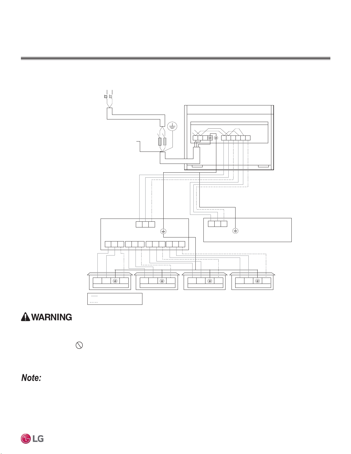
69
Electrical System Installation
Due to our policy of continuous product innovation, some specifications may change without notification.
©LG Electronics U.S.A., Inc., Englewood Cliffs, NJ. All rights reserved. “LG” is a registered trademark of LG Corp.
MULTI
F
MAX
MULTI
F
Figure 89: Multi F MAX LMU480HV and LMU540HV System Power Wiring and Communications Cable.
• All field-supplied wiring, components, and materials must comply with all applicable national, state, and local codes and requirements.
Improper wiring will result in fire, electric shock, physical injury or death.
• Ground wiring is required to prevent accidental electrical shock during current leakage, communication problems from electrical noise, and
motor current leakage.
Do not connect the ground line to the pipes. There is a risk of fire, electric shock, explosion, physical injury or
death.
• Install a main shutoff switch or circuit breaker that interrupts all power sources simultaneously. There is a risk of fire, electric shock, explo-
sion, physical injury or death.
• All field-supplied wiring, components, and materials must comply with all applicable national, state, and local codes and requirements.
Failure to install proper electrical components can result in property damage and equipment malfunction.
• Ground wiring is required to prevent communication problems from electrical noise, and motor current leakage. Failure to provide proper
ground wiring can result in property damage and equipment malfunction.
• Install a main shutoff switch or circuit breaker that interrupts all power sources simultaneously. Failure to install proper electric components
can result in property damage and equipment malfunction.
• Maintain polarity throughout the communication network. The system will malfunction if not properly wired.
ELECTRICAL
,QVWDOODWLRQ
1(L1) 2(L2)
1(L1) 2(L2) 1(L1) 2(L2) 1(L1) 2(L2) 1(L1) 2(L2)
1(L1) 2(L2)
S
S S S S
1(L1) 2(L2) 1(L1) 2(L2) 1(L1) 2(L2) 1(L1) 2(L2)
Indoor Unit Terminal Block
3 3
Outdoor Unit Terminal Block
L
L
N
N
G
Power Supply
Outdoor unit
Main Switch
Circuit Breaker
Three-wire Power Wiring
(Including Ground)
Fuse
* Same Wiring as Branch Distribution Unit (A)
S
Branch Distribution Unit (B)
3 3
COMMUNICATIONS CABLE
POWER WIRING
L1 L2
1(
L1
)2(
L2
)3(A)1(
L1
)2(
L2
) 3 (B)
Branch Distribution Unit (A)
Indoor Unit Terminal Block Indoor Unit Terminal Block Indoor Unit Terminal Block
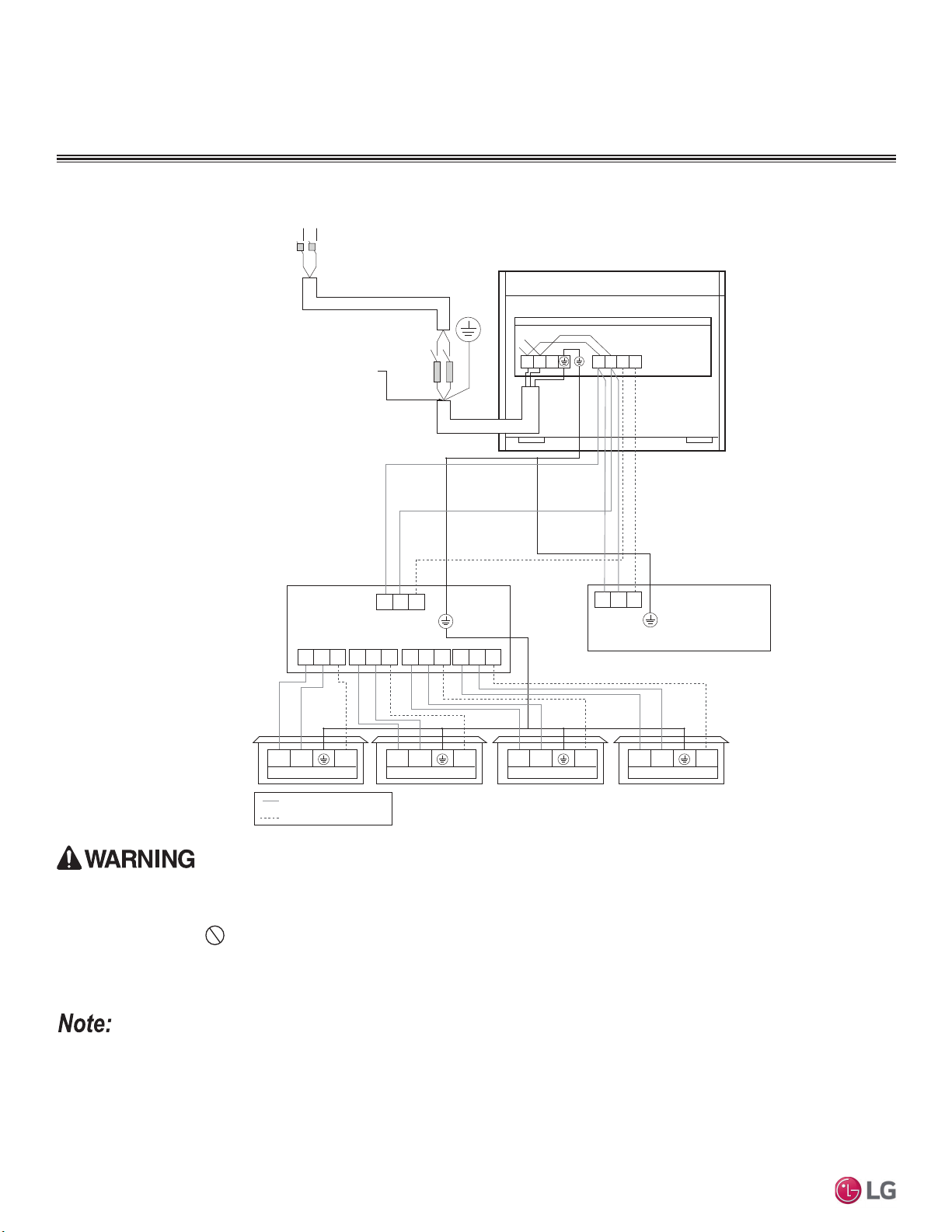
70
MULTI F / MULTI F MAX Outdoor Unit Installation Manual
Due to our policy of continuous product innovation, some specifications may change without notification.
©LG Electronics U.S.A., Inc., Englewood Cliffs, NJ. All rights reserved. “LG” is a registered trademark of LG Corp.
MULTI
F
MAX
MULTI
F
ELECTRICAL
,QVWDOODWLRQ
Figure 90: Multi F MAX LMU600HV System Power Wiring and Communications Cable.
1(L1) 2(L2)
1(L1) 2(L2) 1(L1) 2(L2) 1(L1) 2(L2) 1(L1) 2(L2)
1(L1) 2(L2)
S
S S S S
1(L1) 2(L2) 1(L1) 2(L2) 1(L1) 2(L2) 1(L1) 2(L2)
Indoor Unit Terminal Block
3 3
Outdoor Unit Terminal Block
L
L
N
N
G
Power Supply
Outdoor unit
Main Switch
Circuit Breaker
Three-wire Power Wiring
(Including Ground)
Fuse
* Same Wiring as Branch Distribution Unit (A)
S
Branch Distribution Unit (B)
3 3
COMMUNICATIONS CABLE
POWER WIRING
L1 L2
1(
L1
)2(
L2
)3(A) 3 (B)
Branch Distribution Unit (A)
Indoor Unit Terminal Block Indoor Unit Terminal Block Indoor Unit Terminal Block
• All field-supplied wiring, components, and materials must comply with all applicable national, state, and local codes and requirements.
Improper wiring will result in fire, electric shock, physical injury or death.
• Ground wiring is required to prevent accidental electrical shock during current leakage, communication problems from electrical noise, and
motor current leakage.
Do not connect the ground line to the pipes. There is a risk of fire, electric shock, explosion, physical injury or
death.
• Install a main shutoff switch or circuit breaker that interrupts all power sources simultaneously. There is a risk of fire, electric shock, explo-
sion, physical injury or death.
• All field-supplied wiring, components, and materials must comply with all applicable national, state, and local codes and requirements.
Failure to install proper electrical components can result in property damage and equipment malfunction.
• Ground wiring is required to prevent communication problems from electrical noise, and motor current leakage. Failure to provide proper
ground wiring can result in property damage and equipment malfunction.
• Install a main shutoff switch or circuit breaker that interrupts all power sources simultaneously. Failure to install proper electric components
can result in property damage and equipment malfunction.
• Maintain polarity throughout the communication network. The system will malfunction if not properly wired.
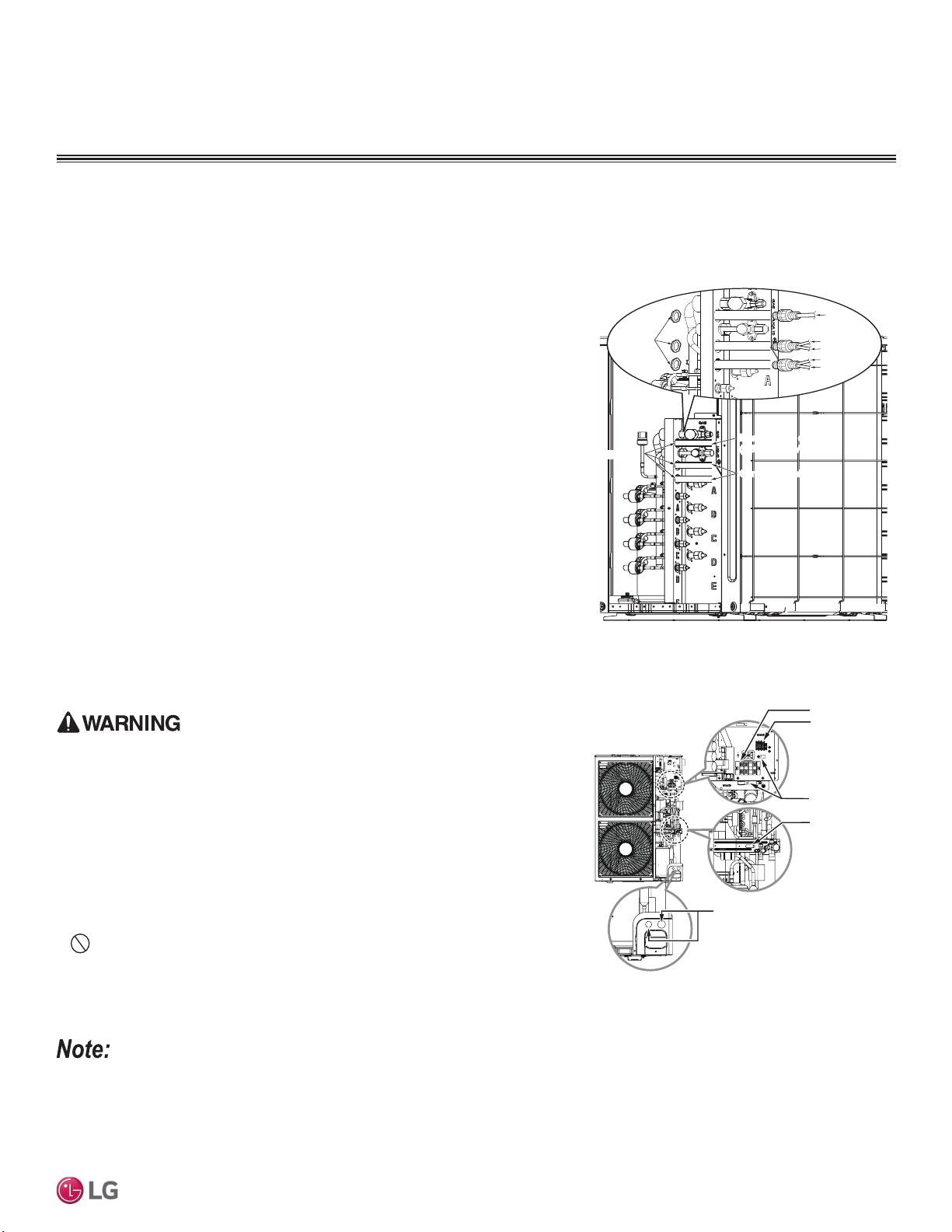
71
Electrical System Installation
Due to our policy of continuous product innovation, some specifications may change without notification.
©LG Electronics U.S.A., Inc., Englewood Cliffs, NJ. All rights reserved. “LG” is a registered trademark of LG Corp.
MULTI
F
MAX
MULTI
F
1. Detach the outdoor unit panels by loosening the screws.
2. Remove the control cover (if applicable) by loosening the screws.
3. Remove the conduit knock outs or access holes.
4. Pull the power wiring, and the communications / connection (power) cable into the
outdoor unit (through the conduits, if applicable). Ensure there is enough length to
connect to the terminals on the outdoor unit. Secure any conduits with field-sup-
plied lock nuts.
5. Connect the power wiring, and the communications / connection (power) cable to
the correct terminals on the outdoor unit.
6. Connect communications / connection (power) cable to the correct control board
terminals on the indoor unit (or branch distribution unit[s] if Multi F MAX system).
7. Follow the wiring diagrams on the outdoor unit and indoor units (or branch distri-
bution unit[s]) control covers. Ensure that the terminal board numbers and wiring
color on the outdoor unit matches the terminal number and wiring color on the
indoor unit or branch distribution unit(s).
8. Provide strain relief and help protect the connections by (separately) securing the
wiring / cable to the outdoor unit with the factory-supplied clamps (up to 35 lbs.).
Clamps are included near the terminal block. Zip ties can also be used to hold all
cables in place.
9. For more installation information for specific indoor units, refer to the separate
indoor unit installation manuals on www.lghvac.com.
10. When all connections are complete, reattach the control cover to its original posi-
tion using the screws, then reinstall the outdoor unit panel.
11. After installation is complete, seal any gaps around the wiring in the panel access
holes or the conduits.
Figure 91: Connecting the Power Wiring / Communi-
cations Cables to the Outdoor Unit (LMU18~36*HV;
LMU480, 540HV) (Appearances Will Vary).
Figure 92: Connecting the Power Wiring / Communi-
cations Cables to the Outdoor Unit (LMU600HV).
• Always have a trained technician properly ground the outdoor unit. If the outdoor unit
is not properly grounded, there is a risk of electric shock, physical injury, or death.
• )DLOXUHWRSURSHUO\LQVWDOOZLULQJFDQUHVXOWLQHOHFWULFVKRFN¿UHSK\VLFDOLQMXU\RUGHDWK
• Failure to properly provide a NEC-approved earth ground can result in electric shock,
fire, physical injury or death.
• Comply with local and national codes while running the wire from the indoor unit
(and branch distribution units if Multi F MAX system) to the outdoor unit (size of wire
and wiring method, etc). Incorrectly sized wiring will cause the terminal to overheat,
generate a fire, and risk physical injury or death.
• All wiring / cable must be firmly connected to its terminal. Loose wiring will cause the
terminal to overheat, generate a fire, and risk physical injury or death.
•
Do not allow the wiring / cable to touch refrigerant tubing, the compressor, or
any moving parts. It can result in electric shock, fire, physical injury or death.
• Replace all control box and panel covers. If cover panels are not installed securely,
dust, water and animals will enter the outdoor unit, causing fire, electric shock, and
physical injury or death.
• Ensure the communications / connection (power) cable from the outdoor units to the indoor / branch distribution units, and the power wiring
to the outdoor unit are separate; otherwise, the outdoor unit operation will be affected by electrical noise and will malfunction or fail.
• The communications / connection (power) cable from the outdoor unit to the indoor / branch distribution units must be separated and
isolated from power wiring to the outdoor unit, computers, elevators, radio and television broadcasting facilities, as well as medical imaging
equipment; otherwise, the outdoor unit operation will be affected by electrical noise and will malfunction or fail.
• All wiring / cable must be firmly connected to its terminals. Loose wiring will result in unit malfunction.
ELECTRICAL
,QVWDOODWLRQ
Power supply cabl
(1Ø, 208/230V)
Power Supply Cable
(1Ø, 208/230V)
Connecting cabl
Connecting Cable
Lock nut
(Field Supplied)
Indoor Unit A
Conduit
(Field Supplied)
Indoor Unit B
Indoor Unit C
Indoor Unit D
Conduit
Hole
Power Wiring
Terminal
Communication / Connection
(Power) Cable Terminal
(To the Indoor Units / Branch
Distribution Units)
Cord Clamp
Cord Clamp
* Make sure the rubber bushes are
properly used in knock-out holes after
connecting the wiring and cables.
&RQQHFWLQJWKH&RPPXQLFDWLRQV&RQQHFWLRQ3RZHU&DEOHV
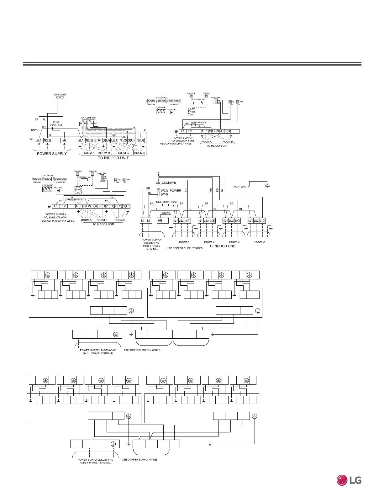
72
MULTI F / MULTI F MAX Outdoor Unit Installation Manual
Due to our policy of continuous product innovation, some specifications may change without notification.
©LG Electronics U.S.A., Inc., Englewood Cliffs, NJ. All rights reserved. “LG” is a registered trademark of LG Corp.
MULTI
F
MAX
MULTI
F
Figure 93: Detailed Diagrams of Outdoor Unit PCB Terminal Connections.
ELECTRICAL
,QVWDOODWLRQ
Indoor Unit Terminal Block
A Unit
Indoor Unit Terminal Block
B Unit
Indoor Unit Terminal Block
C Unit
Indoor Unit Terminal Block
D Unit
Indoor Unit Terminal Block
E Unit
Indoor Unit Terminal Block
F Unit
Indoor Unit Terminal Block
G Unit
Indoor Unit Terminal Block
H Unit
Multi F LMU18CHV
Multi F LMU24CHV
Multi F LMU30CHV and LMU36CHV
Multi F MAX LMU480HV and LMU540HV
BD Unit (A)
BD Unit (A )
A Room B Room C Room D Room A Room B Room C Room D Room
BD Unit (B )
BD Unit (B)
1(L1) 2(L2) 3(A) 1(L1) 2(L2) 3(B) L1 L2
L(L1) N(L2) S L(L1) N(L2) S
1(L1) 2(L2) 3
L(L1) N(L2) S
1(L1) 2(L2) 3
L(L1) N(L2) S
1(L1) 2(L2) 3
L(L1) N(L2) S
1(L1) 2(L2) 3
L(L1) N(L2) S
1(L1) 2(L2) 3
L(L1) N(L2) S
1(L1) 2(L2) 3
L(L1) N(L2) S
1(L1) 2(L2) 3
L(L1) N(L2) S
1(L1) 2(L2) 3
L(L1) N(L2) S
Multi F LMU180HV and LMU240HV
Indoor Unit Terminal Block
A Unit
Indoor Unit Terminal Block
B Unit
Indoor Unit Terminal Block
C Unit
Indoor Unit Terminal Block
D Unit
Indoor Unit Terminal Block
E Unit
Indoor Unit Terminal Block
F Unit
Indoor Unit Terminal Block
G Unit
Indoor Unit Terminal Block
H Unit
Multi F MAX LMU600HV
To BD Units A and B
BD Unit (A )
A Room B Room C Room D Room A Room B Room C Room D Room
BD Unit (B )
1(L1) 2(L2) 3(A) 3(B) L1 L2
L(L1) N(L2) S L(L1) N(L2) S
1(L1) 2(L2) 3
L(L1) N(L2) S
1(L1) 2(L2) 3
L(L1) N(L2) S
1(L1) 2(L2) 3
L(L1) N(L2) S
1(L1) 2(L2) 3
L(L1) N(L2) S
1(L1) 2(L2) 3
L(L1) N(L2) S
1(L1) 2(L2) 3
L(L1) N(L2) S
1(L1) 2(L2) 3
L(L1) N(L2) S
1(L1) 2(L2) 3
L(L1) N(L2) S
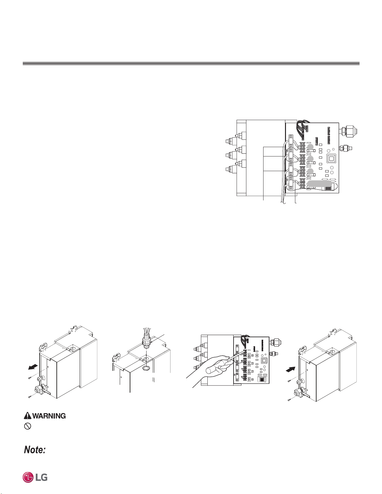
73
Electrical System Installation
Due to our policy of continuous product innovation, some specifications may change without notification.
©LG Electronics U.S.A., Inc., Englewood Cliffs, NJ. All rights reserved. “LG” is a registered trademark of LG Corp.
MULTI
F
MAX
MULTI
F
General Instructions
• Always connect power wiring / communications cable matching the
branch distribution unit terminals to their respective indoor units
(Example for three-port branch distribution unit PMBD3630: A, B,
and C).
• Follow the instructions on the nameplates and connect wiring /
cables of the outdoor unit and indoor units to the correct terminals.
Always attach each ground wire separately to a grounding screw.
• After completion, secure wiring with wire clamps. Secure wiring
firmly to the indoor unit.
'RQRWXVHWDSSHGZLUHVVWDQGZLUHVH[WHQVLRQFRUGVRUVWDUEXUVWW\SHFRQQHFWLRQVDVWKH\ZLOOFDXVHRYHUKHDWLQJ¿UHHOHFWULFVKRFNphysi-
cal injury or death.
Branch Distribution Unit Wiring Connection Procedure
1. Remove the branch distribution unit control cover. Unscrew the two (2) screws, and slide the cover off the branch distribution frame follow-
ing the arrows in the diagram (Step 1).
2. Draw the communications / connection (power) cable from the outdoor unit so there is enough length to connect to the terminals on the
branch distribution unit. Secure a field -supplied conduit to the branch distribution unit using a field-supplied lock nut on the interior of the
branch distribution unit frame (Step 2). Pull the communication / connection (power) cable through the conduit into the branch distribution
unit.
3. Connect communications / connection (power) cable from the outdoor unit to the branch distribution unit terminals, and from the branch
distribution unit terminals to the indoor unit terminals following the wiring diagram on the outdoor unit control cover (Step 3). Allow 11-
13/16 inches of slack in the wire harness. Attach communications / connection (power) cable to the branch distribution unit with clamps at
four (4) locations.
4. Replace the branch distribution unit control cover following the arrows in the diagram. Tighten the two (2) screws to finish (Step 4).
Lock nut (field supply)
Conduit (field supplied)
Lock nut (field supplied)
Step 1
Step 2
Step 3
Step 4
“A” Room
A
B
C
CN-PWR
Connection Wire to Indoor Units Connection Wire from Outdoor Unit
“B” Room
“C” Room
&RQQHFWLQJWKH&RPPXQLFDWLRQV&RQQHFWLRQ3RZHU&DEOHWRWKH%UDQFK
Distributor Unit (Multi F MAX Systems Only)
Always refer to the circuit diagram on the inside of the outdoor unit control cover.
Figure 94: Interior View of a Branch Distribution Unit (Three-Port
PMBD3630 Example Shown).
Figure 95: Branch Distribution Unit Wiring Steps.
ELECTRICAL
,QVWDOODWLRQ
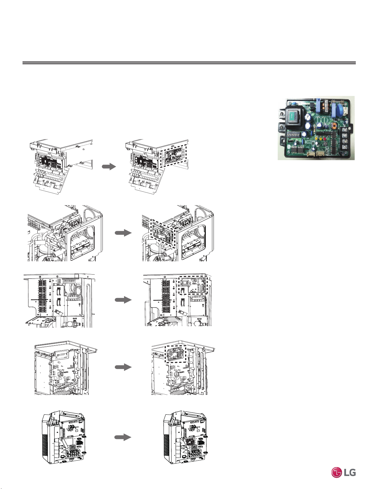
74
MULTI F / MULTI F MAX Outdoor Unit Installation Manual
Due to our policy of continuous product innovation, some specifications may change without notification.
©LG Electronics U.S.A., Inc., Englewood Cliffs, NJ. All rights reserved. “LG” is a registered trademark of LG Corp.
MULTI
F
MAX
MULTI
F
PI-485
PI-485 V-net Control Integration Board for Outdoor Units adapt Multi F / Multi F MAX systems to a LG
VRF system central protocol for integration with LG central controllers. The PI-485 is installed in the
Multi F / Multi F MAX outdoor unit. For more information on PI-485 installation, see the PI-485 installation
manual.
Figure 96: PI-485 Board (Ap-
pearance will differ depending on
model).
Figure 97: PI-485 Installation Area in Multi F and Multi F MAX Outdoor Units.
ELECTRICAL
,QVWDOODWLRQ
Multi F LMU18CHV, LMU24CHV
Multi F LMU30CHV, LMU36CHV
T
hi
s
l
a
b
e
l
i
s
s
h
o
u
l
d
be
app
l
i
ed
i
n
t
h
e
lo
c
a
t
i
o
n
w
h
e
r
e
L
GA
P(Sub
PCB
f
o
r
C
e
n
t
r
a
l
C
o
n
t
r
o
l
l
e
r
i
s
ins
t
a
l
l
e
d
.
Pl
e
as
e
co
n
n
e
c
t
t
h
e
w
i
r
e
a
f
t
e
r
i
n
s
t
a
l
l
i
n
g
t
h
e
L
G
A
P
.
Thi
s
i
s
th
e
s
p
a
c
e
f
o
r
in
s
t
a
l
l
a
ti
o
n
o
f
PI
4
8
5
G
a
te
w
a
y.
(
A
c
c
e
s
s
o
ry
)
Pl
e
a
s
e
c
o
n
n
e
c
t
t
h
e
w
i
r
e
afte
r
i
ns
ta
l
l
i
ng
PI48
5
G
a
tewa
y.
Screw Hole
Screw Hole
M
EZ30
1
71
8
0
2
Multi F MAX LMU480HV, LMU540HV
Multi F MAX LMU600HV
Multi F LMU180HV, LMU240HV
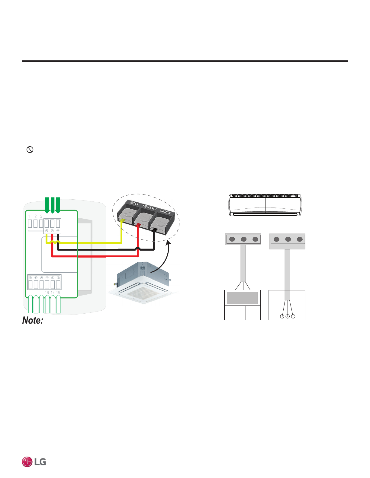
75
Electrical System Installation
Due to our policy of continuous product innovation, some specifications may change without notification.
©LG Electronics U.S.A., Inc., Englewood Cliffs, NJ. All rights reserved. “LG” is a registered trademark of LG Corp.
MULTI
F
MAX
MULTI
F
From Indoor Units to Remote Controllers
• Communication cable from indoor unit to remote controller(s) is to be LG supplied or field supplied 22 AWG, 3-conductor, twisted, stranded,
unshielded. Wiring must comply with all applicable local and national codes.
• ,IXVLQJWKH/*VXSSOLHGFDEOHDQGWKHOHQJWKQHHGVWREHH[WHQGHGWKH/*([WHQVLRQ.LWVROGVHSDUDWHO\PXVWEHXVHG$PD[LPXPRI
four (4) kits (up to 165 feet) can be used.
• Remote controllers have hardwired connections: SIG - 12V - GND (Comm.) terminals.
• Indoor unit controller connections depend on type of indoor unit being installed. Some indoor units use terminal block connections; other
indoor units use Molex connections. See diagrams below for the two options. Refer to the wiring diagram schematic found in the indoor unit
itself, or to the indoor unit wiring diagrams in the Engineering Manuals for more information.
•
NEVER splice, cut, or extend LG supplied cable with field provided cable. Always include enough cable to cover distance between the
indoor unit and the remote controller.
• Set the indoor unit operating parameters using DIP switches, or by setting up the remote controller. Refer to the indoor unit installation
manuals for more details.
Cable connected to Zone Controller is the factory default connection.
Figure 98: One Example of Indoor Unit to Zone Controller Connection.
BACnet+
BACnet-
BACnet Common
Not used
Not used
Not used
Common
456
13 14 15
Typical Indoor Unit
Signal
12VDC
YL
RD
BK
CN-REMO
Indoor Unit
RD
BK
YL
Front
CN-REMO
RDBKYL
Back
Figure 99: Another Example of Indoor Unit to Zone Controller
Connection.
ELECTRICAL
,QVWDOODWLRQ
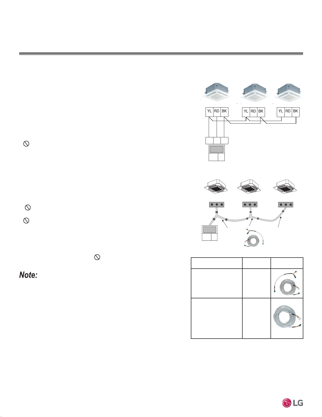
76
MULTI F / MULTI F MAX Outdoor Unit Installation Manual
Due to our policy of continuous product innovation, some specifications may change without notification.
©LG Electronics U.S.A., Inc., Englewood Cliffs, NJ. All rights reserved. “LG” is a registered trademark of LG Corp.
MULTI
F
MAX
MULTI
F
Between Multiple Indoor Units Operating as a
Group (Group Control)
If any indoor units were specified to operate in unison:
• Before running cable, decide which indoor unit will be the “Main.” The other indoor
units in that group will be designated as “Sub(s).” The zone controller will be connected
to the “Main.”
• Set the pertinent DIP switch at each indoor unit to identify the Main and Sub(s). On
wall mounted indoor unit models, set the assignment using the handheld remote
controller.
• Use a daisy chain configuration and connect all of the group’s indoor units together
starting at the “Main” unit.
•
NEVER splice, cut, or extend cable length with field provided cable. Always
include enough cable to cover distance between all components.
For indoor units with hardwired connections SIG - 12V - GND (Comm.)
terminals:
• From the controller to the main indoor unit, use 22 AWG, 3-conductor, twisted, strand-
ed, unshielded. All wiring must comply with all applicable local / national codes.
• From the main indoor unit to the sub indoor unit(s), daisy chain using 22 AWG, 3-con-
ductor, twisted, stranded, unshielded. All wiring must comply with all applicable local /
national codes.
• (
Do not attach wire to 12VDC terminal to the sub indoor units). All wiring must
comply with all applicable local and national codes.
• NEVER splice, cut, or extend cable length; always include enough cable to cover
distance between all components.
For indoor units with CN-REMO connections:
8VHRQHRUPXOWLSOH*URXS&RQWURO.LWVVROGVHSDUDWHO\FRQWDLQLQJH[WHQVLRQDQG
Y-splitter cables. Use one (1) group control cable kit for each indoor unit in the
group except for the last indoor unit.
NEVER splice, cut, or extend cable
length with field provided cable.
• Cable connected to zone controller is the factory default connection.
• Indoor unit connections depend on indoor unit type.
Figure 100: Example of Indoor Unit Group to Zone
Controller Connections (Sig-12V-GND [Comm.]
Terminal).
Figure 101: Example of Indoor Unit Group to Zone
Controller Connections (CN-REMO).
Main Indoor Unit
Indoor Unit
Indoor Unit
Signal
12VDC Comm.
Signal
12VDC Comm.
45
6
Signal
12VDC Comm.
Signal
12VDC Comm.
CN-REMO
On All Indoor Unit Styles
CN-REMO
On All Indoor Unit Styles
CN-REMO
On All Indoor Unit Styles
LG
Supplied
LG Supplied Group Control Kit (PZCWRCG3)
Accessory
Model
Number
Image
Wired Remote Group
Control Cable Assembly,
Required for connecting
multiple indoor units to a
control group
PZCWRCG3
Wired Remote/Wired
Remote Extension Cable,
Required for extending
the distance between
indoor units or remote
controllers in a control
group
PZCWRC1
Table 34: Accessories for Some Group Control Applications.
General Specifications
• Wired remote controllers can be connected to all indoor unit types.
• Wireless controllers can be used in conjunction with wired remote controllers.
• A dry contact unit can be connected with a central controller simultaneously.
- The main indoor unit is recognized by the dry contact unit and the central
controller.
- Group Control only available for indoor units manufactured after February 2009.
- The central controller can control indoor units after setting the address of the main indoor unit only.
- Sub indoor unit cannot be individually controlled by central controller.
- Sub indoor unit will operate like the main indoor unit.
• If an error occurs with the indoor unit, the error will be displayed on the wired remote controller.
• The following functions are available with group control:
• Selection of operation options (operation/mode/set temperature)
• Control of air flow rate (High/Medium/Low)
ELECTRICAL
,QVWDOODWLRQ
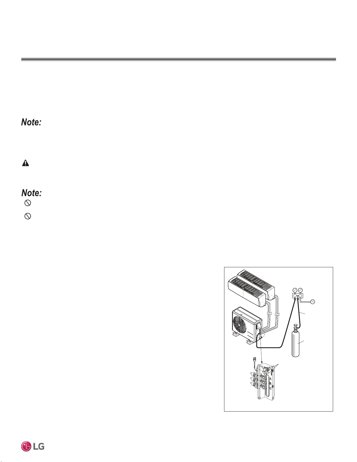
77
Final Installation Procedures
Due to our policy of continuous product innovation, some specifications may change without notification.
©LG Electronics U.S.A., Inc., Englewood Cliffs, NJ. All rights reserved. “LG” is a registered trademark of LG Corp.
MULTI
F
MAX
MULTI
F
7ULSOH/HDN3UHVVXUH7HVW
After the refrigerant piping installation is complete, perform a triple leak / pressure test. Triple leak / pressure test is performed between the
outdoor unit and indoor units (and branch distribution units [Multi F MAX only]) to verify that refrigerant can flow through the system without
danger of leaks or pressure losses. Air and moisture that is left in the piping can lead to undesirable results and can cause damage to the
system. It is important to go through a complete leak / pressure cycle to be sure that the refrigerant piping is cleared out. This process will
have to be repeated if any air or moisture be is found to remain in the piping.
• Pressure in the system can rise.
• Operating current can rise.
• Inefficient cooling or heating mode capability.
• Moisture in the refrigerant circuit will freeze and block capillary
tubing.
• Water can lead to corrosion of parts in the system.
Figure 102: Triple Leak / Pressure Test Diagram.
,QVXI¿FLHQWRULQFRUUHFWO\GRQHDLUSXUJLQJZLOOOHDGWRWKHIROORZLQJ
DANGER
8VLQJFRPEXVWLEOHJDVHVLQFOXGLQJR[\JHQZLOOUHVXOWLQ¿UHRUH[SORVLRQUHVXOWLQJLQSHUVRQDOLQMXU\RUGHDWK8VHLQHUWJDVPHGLFDOJUDGHGU\QLWUR-
gen) when checking leaks, cleaning, installing/repairing pipes, etc. The use of at least 800 psig nitrogen regulator is required for safety.
• Do not apply power to the system before performing a system leak test. There is a possibility that the EEV valve will close and isolate
sections of the piping system, making the leak test inconclusive.
• Never perform the leak test using refrigerant.
• To avoid nitrogen entering the refrigerant system in a liquid state, the top of the cylinder must be higher than its bottom (used in a vertical
standing position) when the system is pressurized.
• Use only a leak-free gauge manifold set.
• Piping system must not be pressured to more than 550 psi. Pressures greater than 550 psi will damage the piping system and cause unit
malfunction.
Triple Leak / Pressure Check Procedure
1. After the refrigerant piping installation is complete, open the isolation ball valves, if
any, that could have been included in the piping system.
2. Verify that both the liquid and gas (vapor) suction line outdoor unit service ports are
closed, and the stem head access caps are tight. The leak / pressure check is to be
performed only to the refrigerant piping system, and all connected indoor units and
branch distribution units (Multi F MAX units only).
3. Remove the caps on both the liquid and gas (vapor) suction Schrader ports. Con-
nect the (medical-grade dry) nitrogen cylinder regulator to a gauge manifold, then
connect the gauge manifold to the Schrader ports on the service ports.
4. Perform the leak / pressure check at 150 psig for fifteen (15) minutes (standing
pressure check).
5. Perform the leak / pressure check at 300 psig for thirty (30) minutes (standing
pressure check).
6. Perform the leak / pressure check at 550 psig for one (1) hour to make sure the
piping system is leak-free. After the gauge reading reaches 550 psig, isolate the
system by first closing the gauge manifold, then close the nitrogen cylinder valve.
Check the flared (and any brazed connections) for leaks by applying a bubble
solution to all joints. Also test for leaks at both service valves.
FINAL INSTALLATION PROCEDURES
Charge Hose
Nitrogen Gas
Cylinder (with
cylinder upright)
Indoor Units
Outdoor Unit
Lo Hi
Manifold Valve
Pressure
Gauge
Appearances will vary depending on model.
Service Ports
7ULSOH/HDN3UHVVXUH7HVW
78
MULTI F / MULTI F MAX Outdoor Unit Installation Manual
Due to our policy of continuous product innovation, some specifications may change without notification.
©LG Electronics U.S.A., Inc., Englewood Cliffs, NJ. All rights reserved. “LG” is a registered trademark of LG Corp.
MULTI
F
MAX
MULTI
F
Triple Leak / Pressure Check Procedure, continued.
The bubble solution must be a solution designed for refrigerant leak testing. Common soap solution must never be used on refrigerant piping as
those contain chemicals that could corrode copper and brass, and cause product malfunction.
7. If the pressure does NOT drop for one (1) hour, the system passes the test.
8. If the pressure drops, there is a leak and it must be found. Remove the bubble solution with a clean cloth, repair the leak(s), and perform
the leak / pressure check again.
9. After the system has been thoroughly tested and no leaks are found, depressurize by loosening the charging hose connector at the nitro-
gen cylinder regulator. When system pressure returns to normal, completely disconnect the charging hose from the cylinder, and release
the nitrogen charge from all refrigerant piping. Wipe off any remaining bubble solution with a clean cloth.
7ULSOH/HDN3UHVVXUHDQG'HHS(YDFXDWLRQ7HVWV
FINAL INSTALLATION PROCEDURES
Deep Evacuation Procedure
On Multi F systems, after the leak / pressure check is complete, the deep evacuation procedure must be performed to the refrigerant piping
and all connected indoor units. On Multi F MAX systems, the triple evacuation procedure (seen on page 79) must be performed. Deep evacu-
ation must be performed through the Schrader ports on the outdoor unit service ports.
The triple evacuation procedure seen on page 79 is a best practices recommendation for Multi F systems, but mandatory for Multi F MAX systems.
For faster evacuation, the Schrader core can be removed, and an auxiliary service port can used. Make sure to re-install the original Schrader core
before operating the system.
• Deep evacuate through both the liquid and gas (vapor) suction Schrader ports on the outdoor unit service ports.
• The outdoor unit service valves must remain closed and the stem head access caps tight.
Do not open the outdoor unit service valves
and release the factory refrigerant charge until trim charge is complete, and the system is ready to operate.
• Any field-installed ball valves in the refrigerant system (if used) must be open to ensure all piping is free and clear for deep evacuation on
all piping and connected indoor units.
• Do not apply power to the system before performing the deep evacuation procedure. There is a possibility that the EEV valve will close
and isolate sections of the piping system, making the deep evacuation procedure inconclusive.
•
Never perform evacuation using refrigerant.
• Use only a vacuum pump that can reach 500 microns, vacuum rated hoses or copper tubing, and a leak-free gauge manifold set.
• Use only new vacuum pump oil from a properly sealed (unopened) container, and change oil in pump before EVERY use.
• Subsequent oil changes will be necessary after several hours of continuous operation; have extra oil on hand.
• Use a quality micron gauge in good operating order and install as far away from pump as possible.
Deep Evacuation Procedure Steps
1. If this procedure is performed shortly after the leak / pressure test, the cap and core on the liquid and gas (vapor) suction Schrader ports
must have already been removed, and the manifold must already be connected. If the procedure was not performed shortly after the leak
/ pressure test, make sure to remove the cap and core on the liquid and gas (vapor) suction Schrader ports. Verify that the service valves
on the outdoor unit are closed, and the stem head access caps are tight.
2. Connect the gauge manifold along with the vacuum pump to the liquid and gas (vapor) suction Schrader ports (with core removed) using a
vacuum hose. Open the gauge manifold and the vacuum pump valves.
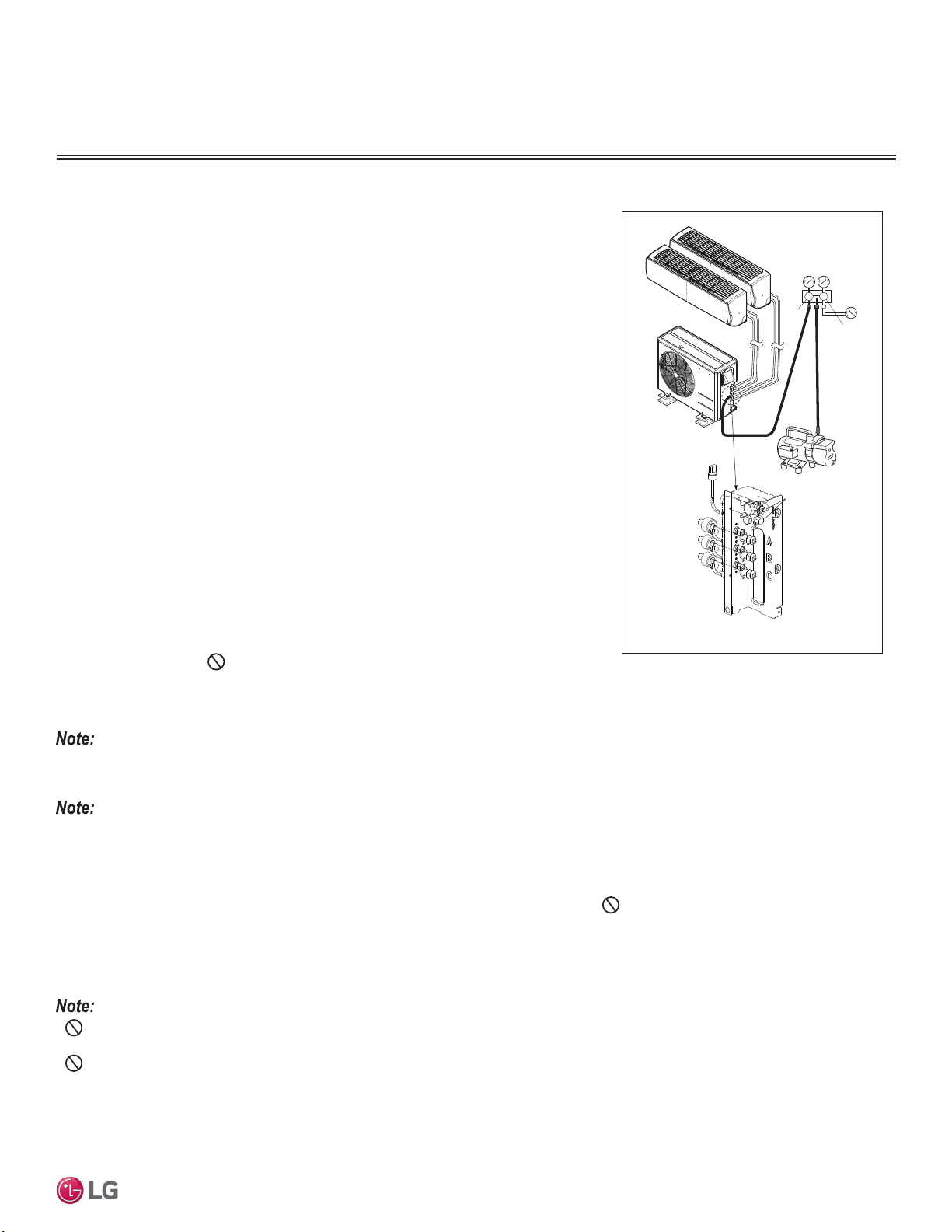
79
Final Installation Procedures
Due to our policy of continuous product innovation, some specifications may change without notification.
©LG Electronics U.S.A., Inc., Englewood Cliffs, NJ. All rights reserved. “LG” is a registered trademark of LG Corp.
MULTI
F
MAX
MULTI
F
Triple Evacuation Procedure
On Multi F MAX systems, after the leak / pressure check is complete, the triple evacuation
procedure must be performed to the refrigerant piping and all connected indoor units /
branch distribution units.
Do not just perform the deep evacuation procedure on Multi F
MAX systems. The deep evacuation procedure is insufficient to fully evacuate the extensive
piping systems on Multi F MAX products. Triple evacuation must be performed through the Schrader ports on the outdoor unit service ports.
The triple evacuation procedure is a best practices recommendation for Multi F systems, but mandatory for Multi F MAX systems.
For faster evacuation, the Schrader core can be removed, and an auxiliary service port can used. Make sure to re-install the original Schrader core
before operating the system.
• Evacuate through both the liquid and gas (vapor) suction Schrader ports on the outdoor unit service ports.
• The outdoor unit service valves must remain closed and the stem head access caps tight.
Do not open the outdoor unit service valves
and release the factory refrigerant charge until trim charge is complete, and the system is ready to operate.
• Any field-installed ball valves in the refrigerant system (if used) must be open to ensure all piping is free and clear for evacuation on all
piping and connected indoor units / branch distribution units.
• Do not apply power to the system before performing the evacuation procedure. There is a possibility that the EEV valve will close and
isolate sections of the piping system, making the evacuation procedure inconclusive.
• Never perform evacuation using refrigerant.
• Use only a vacuum pump that can reach 500 microns, vacuum rated hoses or copper tubing, and a leak-free gauge manifold set.
• Use only new vacuum pump oil from a properly sealed (unopened) container, and change oil in pump before EVERY use.
• Subsequent oil changes will be necessary after several hours of continuous operation; have extra oil on hand.
• Use a quality micron gauge in good operating order and install as far away from pump as possible.
Deep Evacuation Procedure, continued.
3. (YDFXDWHWRVWDWLFPLFURQOHYHOIRUDWOHDVWRQHKRXU
4. 0LFURQOHYHOPXVWUHPDLQIRUWZRKRXUV,IWKHYDFXXPJDXJHULVHVDQGVWRSV
the system could contain moisture; therefore, it will be necessary to repeat the steps of
vacuum break and drying.
5. After maintaining the system in vacuum for two (2) hours, check if the vacuum gauge
rises or not. If it doesn’t rise, then the system is properly evacuated.
6. Close manifold gauges.
7. Shut the valves before turning off and disconnecting the vacuum pump.
Figure 103: Evacuation Procedure Diagram.
Lo Hi
Vacuum Pump
Open
Open
Indoor Units
Outdoor Unit
Manifold Valve
Pressure
Gauge
Service Ports
Appearances will vary depending on model.
'HHS(YDFXDWLRQ7ULSOH(YDFXDWLRQ7HVWV
FINAL INSTALLATION PROCEDURES
80
MULTI F / MULTI F MAX Outdoor Unit Installation Manual
Due to our policy of continuous product innovation, some specifications may change without notification.
©LG Electronics U.S.A., Inc., Englewood Cliffs, NJ. All rights reserved. “LG” is a registered trademark of LG Corp.
MULTI
F
MAX
MULTI
F
Triple Evacuation Procedure Steps
1. If this procedure is performed shortly after the leak / pressure test, the cap and core on the liquid and gas (vapor) suction Schrader ports
must have already been removed, and the manifold must already be connected. If the procedure was not performed shortly after the leak
/ pressure test, make sure to remove the cap and core on the liquid and gas (vapor) suction Schrader ports. Verify that the service valves
on the outdoor unit are closed, and the stem head access caps are tight.
2. Connect the gauge manifold along with the vacuum pump to the liquid and gas (vapor) suction Schrader ports (with core removed) using a
vacuum hose. Open the gauge manifold and the vacuum pump valves.
• After the vacuum pump is first operated, if hoses, manifold, and vacuum valves are leak free (and oil is not moisture laden), the gauge must
read <100 microns within one (1) minute.
• Do not proceed if the gauge does not read <100 microns within one (1) minute. There is a leak in the hose, gauge manifold, or vacuum
valve, and the equipment must be replaced.
3. Operate the vacuum pump and evacuate the system to the 2,000 micron level. Isolate the pump by closing the manifold gauges and the
YDFXXPSXPSYDOYHDQGWKHQZDWFKWKHPLFURQOHYHO0LFURQOHYHOZLOOULVHDELWEXW0867HYHQWXDOO\VWRSULVLQJIRU¿IWHHQPLQXWHV
• If the micron level DOES NOT stop rising, there is a leak, and the leak test must be performed again.
• If the micron level DOES rise above 2,000 micron, re-open the manifold gauges and the vacuum pump valve and continue evacuation back
down to 2,000 micron level.
• If the micron level holds at 2,000 micron, continue to step 4.
4. Break vacuum with 50 psig nitrogen purge for an appropriate amount of time (this is to “sweep” moisture from piping).
5. Purge nitrogen from the system until the pressure drops down to 1 to 3 psig.
6. Evacuate to 1,000 micron level. Isolate the pump by closing the manifold gauges and the vacuum pump valve, and then watch the micron
level. Micron level will rise a bit, but MUST eventually stop rising for fifteen (15) minutes.
• If the micron level DOES NOT stop rising, there is a leak, and the leak test must be performed again.
• If the micron level DOES rise above 1,000 micron, re-open the manifold gauges and the vacuum pump valve, and continue evacuation back
down to 1,000 micron level.
• If the micron level holds at 1,000 micron, continue to step 7.
7. Break vacuum with 50 psig nitrogen purge for an appropriate amount of time.
8. Purge nitrogen from the system until the pressure drops down to 1 to 3 psig.
9. (YDFXDWHWRVWDWLFPLFURQOHYHOIRUDWOHDVWRQHKRXU
10. 0LFURQOHYHOPXVWUHPDLQIRURQHKRXU,IWKHYDFXXPJDXJHULVHVDQGVWRSVWKHV\VWHPFRXOGFRQWDLQPRLVWXUHWKHUHIRUHLWZLOO
be necessary to repeat the steps of vacuum break and drying.
11. After maintaining the system in vacuum for one (1) hour, check if the vacuum gauge rises or not. If it doesn’t rise, then the system is
properly evacuated.
12. Close manifold gauges.
13. Shut the valves before turning off and disconnecting the vacuum pump.
7ULSOH(YDFXDWLRQ7HVW
FINAL INSTALLATION PROCEDURES
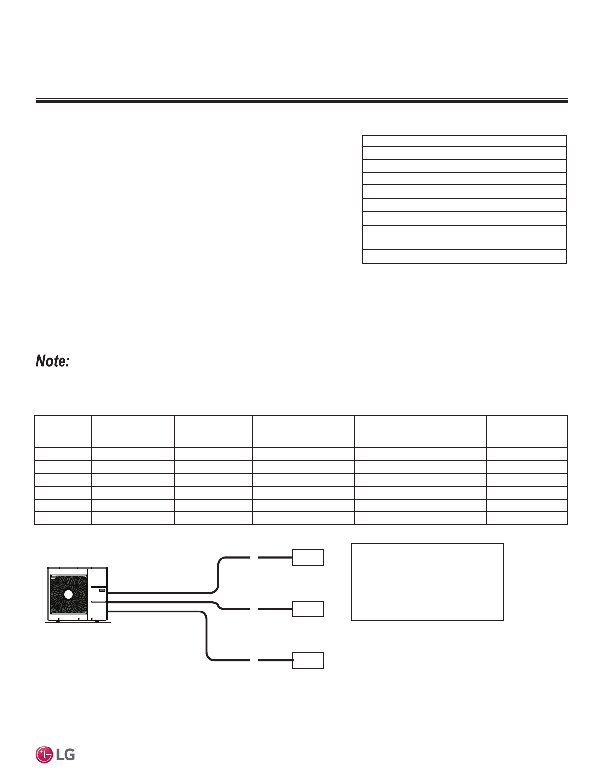
81
Final Installation Procedures
Due to our policy of continuous product innovation, some specifications may change without notification.
©LG Electronics U.S.A., Inc., Englewood Cliffs, NJ. All rights reserved. “LG” is a registered trademark of LG Corp.
MULTI
F
MAX
MULTI
F
5HIULJHUDQW&KDUJH
LG Multi F and Multi F MAX outdoor units ship from the factory with a charge of
R410A refrigerant. A trim charge will need to be added to take into account addition-
al piping length.
To determine the additional refrigerant that is needed, apply the formulas below,
and record the results. If the total additional refrigerant charge value is a negative
number, then an additional trim charge does not need to be added to the system.
Table 35: Outdoor Unit Factory Charge.
Multi F Systems
• Number of installed length of branches depends on the specifications of the outdoor unit model.
• CF = Maximum number of connectible indoor units – Total number of connected indoor units.
Table 36: 0XOWL)2XWGRRU8QLW3LSLQJ6SHFL¿FDWLRQV
Figure 104: Multi F Additional Refrigerant Charge Example.
FINAL INSTALLATION PROCEDURES
Additional charge (lbs.) = (Installed Length of Branch [A] – Chargeless Pipe Length [L]) x a
+ (Installed Length of Branch [B] – Chargeless Pipe Length [L]) x a
+ (Installed Length of Branch [C] – Chargeless Pipe Length [L]) x a
+ (Installed Length of Branch [D] – Chargeless Pipe Length [L]) x a
- CF (Correction Factor) x 5.29
Outdoor Unit
Model
Min. to Max. Piping
Length for One
Branch (ft.)
Max. Total System
Piping Length (ft.)
Chargeless Pipe Length
per Branch (L) (ft.)
Piping Length (No Additional
Refrigerant [ft])
Additional Charge
Needed (a) (oz./ft.)
LMU180HV 9.8 to 82 164 24.6 98.4 0.22
LMU18CHV 9.8 to 82 164 24.6 49.2 0.22
LMU240HV 9.8 to 82 230.0 24.6 98.4 0.22
LMU24CHV 9.8 to 82 246.1 24.6 73.8 0.22
LMU30CHV 9.8 to 82 246.1 24.6 98.4 0.22
LMU36CHV 9.8 to 82 246.1 24.6 98.4 0.22
Outdoor Unit Factory Charge lbs. of R410A
LMU180HV 3.97
LMU18CHV 3.96
LMU240HV 3.97
LMU24CHV 3.96
LMU30CHV 6.18
LMU36CHV 6.18
LMU480HV 9.7
LMU540HV 9.7
LMU600HV 12.3
Each branch pipe
A = 82 ft.
B = 16 ft.
C = 49 ft.
Additional Charge
A
B
C
9,000
9,000
9,000
Example: LMU36CHV
= (82 - 24.6) x 0.22
+ (16 - 24.6) x 0.22
+ (49 - 24.6) x 0.22
- (4 - 3) x 5.29
= 10.82 oz.
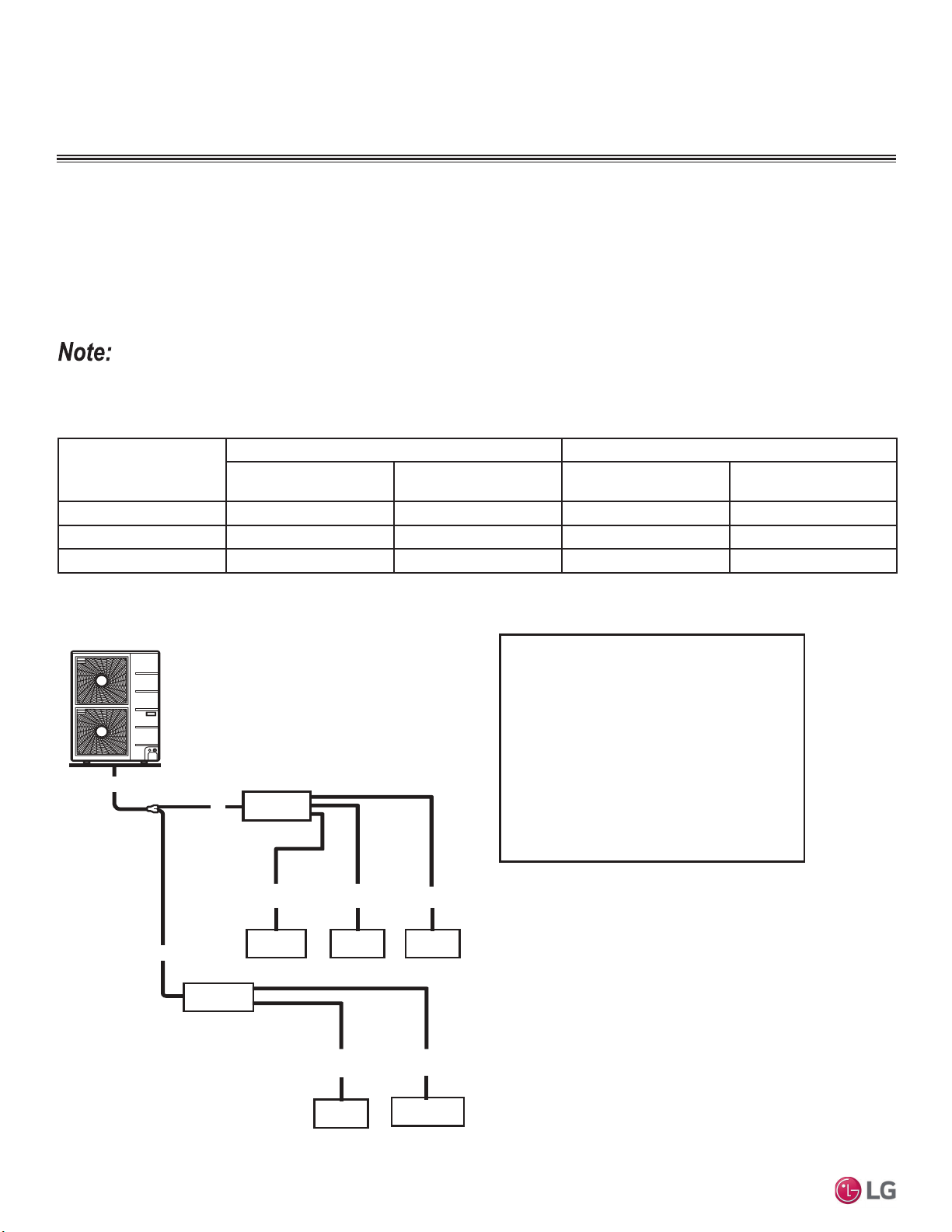
82
MULTI F / MULTI F MAX Outdoor Unit Installation Manual
Due to our policy of continuous product innovation, some specifications may change without notification.
©LG Electronics U.S.A., Inc., Englewood Cliffs, NJ. All rights reserved. “LG” is a registered trademark of LG Corp.
MULTI
F
MAX
MULTI
F
5HIULJHUDQW&KDUJH
Multi F MAX Systems
Table 37: 0XOWL)0$;2XWGRRU8QLW3LSLQJ6SHFL¿FDWLRQV
• Number of installed length of branches depends on system specifications.
• CF = Maximum number of connectible indoor units – Total number of connected indoor units
Figure 105: Multi F MAX Additional Refrigerant Charge Example.
FINAL INSTALLATION PROCEDURES
Outdoor Unit Model
Main Piping Length Branch Piping Length
Chargeless Pipe Length
of Main Pipe (L) (ft.)
Additional Charge
Needed (a) (oz./ft.)
Chargeless Pipe Length
per Branch Pipe (B) (ft.)
Additional Charge
Needed (b) (oz./ft.)
LMU480HV 16.4 0.54 16.4 0.22
LMU540HV 16.4 0.54 16.4 0.22
LMU600HV 16.4 0.54 16.4 0.22
Additional charge (lbs.) = (Total Main Piping Length [A] - Chargeless Pipe Length of Main Pipe [L]) x a
+ (Installed Length of Branch [B1] – Chargeless Pipe Length [B]) x b
+ (Installed Length of Branch [B2] – Chargeless Pipe Length [B]) x b
+ (Installed Length of Branch [B3] – Chargeless Pipe Length [B]) x b ...
- CF (Correction Factor) x 3.53
B3
18,000 9,000 9,000
LMU420HV
• Total main pipe (A) = 60 ft.
• Each branch pipe
B1 =
B2 =
B3 =
B4 =
B5 =
Additional Charge
= (60 - 16.4) x 0.54
+ (49 - 16.4) x 0.22
+ (17 - 16.4) x 0.22
+ (17 - 16.4) x 0.22
+ (10 - 16.4) x 0.22
+ (23 - 16.4) x 0.22
– (8 - 5) x 3.53
= 20.43 oz.
A
49 ft.
17 ft.
17 ft.
10 ft.
23 ft.
BD Unit
BD Unit
9,000 18,000
A
A
B1 B2
B4 B5
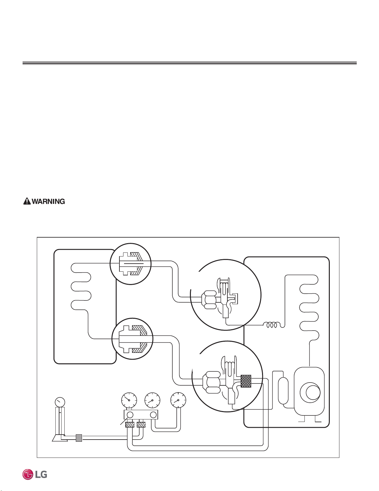
83
Final Installation Procedures
Due to our policy of continuous product innovation, some specifications may change without notification.
©LG Electronics U.S.A., Inc., Englewood Cliffs, NJ. All rights reserved. “LG” is a registered trademark of LG Corp.
MULTI
F
MAX
MULTI
F
Refrigerant Charge
1. Determine the refrigerant that is needed, applying the necessary formulas as outlined in the previous pages.
2. Connect the charging cylinder to the charge hose on the manifold valve.
3. Purge air from the charge hose by opening the valve at the bottom of the cylinder, and press the check valve on the manifold valve.
4. Confirm that the “Lo” knob of the manifold valve is open and charge the system with liquid refrigerant. (Because R-410A is a non-azeo-
trope refrigerant, it must be charged in the liquid state.)
• If the required amount of refrigerant cannot be charged all at once, the refrigerant can be charged a little at a time (approximately 5.29
ounces) while the system operates in cooling. This procedure must be repeated until the entire amount of refrigerant gets charged into
the system; perform once, then wait approximately one [1] minute before resuming.
5. Immediately disconnect the charge hose from the service port on the three-way valve. Stopping halfway allows the refrigerant to
discharge.
• If the system has been charged with liquid refrigerant while it operates, turn the system off before disconnecting the hose.
6. Mount the valve stem nuts and the service port nut. Use torque wrench to tighten the service port nut to a torque of 1.8 kg.m and check
for leaks.
:KHQLQVWDOOLQJRUUHORFDWLQJWKHRXWGRRUXQLWPDNHVXUHWKDWQRVXEVWDQFHRWKHUWKDQWKHVSHFL¿HGUHIULJHUDQW5$HQWHUVWKHUHIULJHUDQWFLUFXLW
The presence of foreign substances such as air can cause an abnormal pressure rise and will result in explosion and physical injury.
Lo
Refrigerant
Cylinder
Outdoor Unit
Indoor Unit
Liquid Piping
Gas Piping
Open
Three-Way
Valve
Three-Way
Valve
OPEN
Open
Check Valve
(One)
Vacuum
Gauge
Figure 106: Charging the Refrigerant.
5HIULJHUDQW&KDUJH
FINAL INSTALLATION PROCEDURES
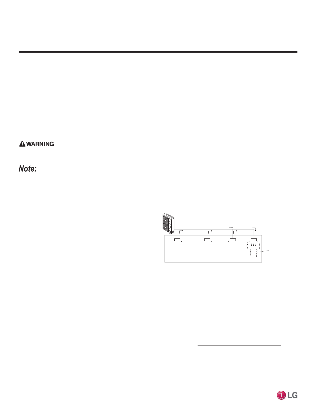
84
MULTI F / MULTI F MAX Outdoor Unit Installation Manual
Due to our policy of continuous product innovation, some specifications may change without notification.
©LG Electronics U.S.A., Inc., Englewood Cliffs, NJ. All rights reserved. “LG” is a registered trademark of LG Corp.
MULTI
F
MAX
MULTI
F
Amount of
Factory-Charged
Refrigerant per
Outdoor Unit
Amount of
Additional
Refrigerant
Trim Charge
Refrigerant Concentration Limit (RCL) Calculations
To calculate total refrigerant amount per system:
&DXWLRQVIRU5HIULJHUDQW/HDNV,QWURGXFWLRQ
ASHRAE Standards 15 and 34 offer guidelines that address refrigerant safety and the maximum allowable concentration of refrigerant in an
occupied space. Refrigerant will dissipate into the atmosphere, but a certain volume of air is required for this to occur safely. For R410A re-
frigerant, the maximum allowable concentration is 0.026 lbs./ft
3
per 1,000 ft
3
of air in an occupied space. Buildings with twenty-four (24) hour
occupancy allow half of that concentration.
1
ASHRAE Standards 15 and 34 assume that if a system develops a leak, its entire refrigerant charge will dump into the area where the leak
occurs. To meet ASHRAE Standards 15 and 34, calculate the refrigerant concentration that will occur in the smallest room volume on
the system, and compare the results to the maximum allowable concentration number (see below for information on how to calculate the
refrigerant concentration).
1
Also consult state and local codes in regards to refrigerant safety.
1
American Society of Heating, Refrigeration and Air Conditioning Engineers, Inc. (ASHRAE). Atlanta, GA. ASHRAE, Inc. Information about
ASHRAE Standard 15 / 34 and addenda current as of the date of this publication.
Take appropriate actions at the end of HVAC equipment life to recover, recycle, reclaim or destroy R410A refrigerant according to applicable US EPA
rules.
Total System
Refrigerant
Charge
+ =
To calculate the potential refrigerant concentration level (RCL):
1. Measure the occupied space dimensions (in feet).
2. Calculate the cubic foot volume of air in the smallest occupied
space. (To obtain a detailed overview of the RCL, perform the
same calculations to the second smallest zone, the third smallest
zone until the RCL is obtained for all zones. Also, pay special
attention to areas such as basements, etc., where refrigerant
cannot dissipate easily.)
3. Divide the refrigerant charge of the Multi Zone system serving the
area in pounds by the results of step 1.
4. If the calculation indicates that the potential refrigerant concen-
tration level is higher than the allowed RCL, increase the cubic
volume of the smallest occupied space or modify the piping
system design.
5. The allowable RCL limit for most applications must be equal to
or less than 0.026 lbs./ft
3
. However, in special occupied spaces,
such as hospitals and nursing homes, where occupants will have
limited mobility, the allowable RCL limit is cut in half. See ASHRAE
Standard 34 and local codes for detailed information.
1
RCL (lbs./ft
3
) =
Total System Refrigerant Charge (lbs.)
Volume of Smallest Occupied Space (ft
3
)
Verify the maximum refrigerant concentration level in the space where the indoor unit will be mounted meets the concentration limit for the applica-
tion. If the refrigerant leaks and safety limits are exceeded, it could result in personal injuries or death from oxygen depletion.
Outdoor Unit
Direction of Refrigerant Flow
Indoor Unit
Zone into which the
entire charge of
refrigerant leaks.
Indoor Unit Indoor Unit
Indoor Unit
Figure 107: Example of R410A Refrigerant Leak Location.
&DXWLRQVIRU5HIULJHUDQW/HDNV
FINAL INSTALLATION PROCEDURES
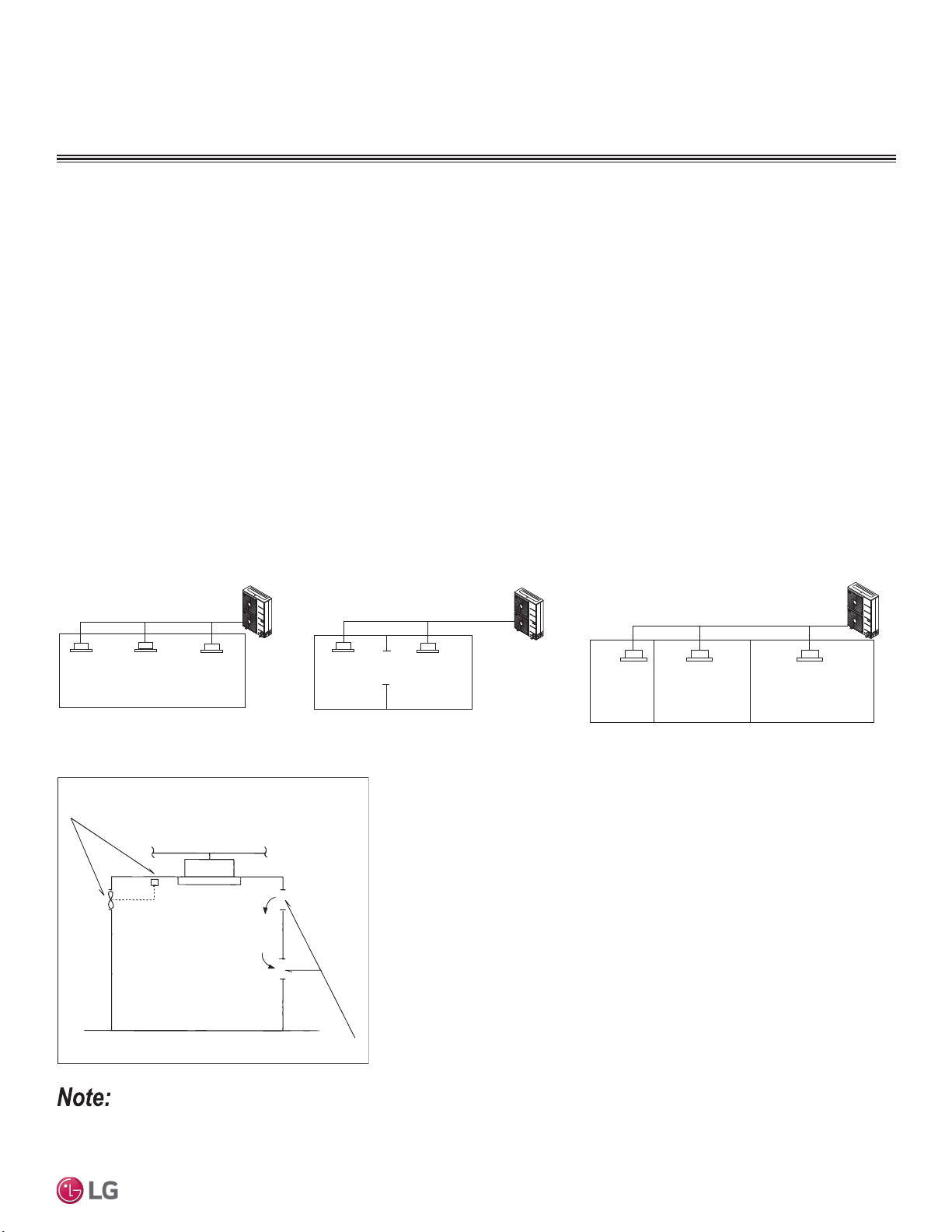
85
Final Installation Procedures
Due to our policy of continuous product innovation, some specifications may change without notification.
©LG Electronics U.S.A., Inc., Englewood Cliffs, NJ. All rights reserved. “LG” is a registered trademark of LG Corp.
MULTI
F
MAX
MULTI
F
To determine the volume of an occupied space, the designer must also determine which ones are connected, not connected, or ventilated
(refer to Standard 34).
If the calculated RCL is above the allowable limit, there are two primary methods used to lower the RCL:
1. Increase the volume of the occupied space.
2. Decrease the size of the refrigerant charge.
Per Standard 34-2007, acceptable methods used to increase the volume of an occupied space include:
• Install transfer ducts between rooms.
• 8QGHUFXWDQGRYHUFXWGRRUVSDUWLWLRQVRIFXELFYROXPHRIVSDFHZLWKLQD]RQH
• $GGDQRSHQLQJZLWKRXWDGRRUSDUWLWLRQVRIFXELFYROXPHRIVSDFHZLWKLQD]RQH
• ,QFOXGHYHQWLODWLRQJULOOHVLQGRRUVLQFOXGHYHQWLODWLRQLQOHWVRXWOHWVSDUWLWLRQVRIFXELFYROXPHRIVSDFHZLWKLQD]RQH
• ,QFOXGHWKHDUHDDERYHWKHFHLOLQJDVSDUWRIWKHUHWXUQRUVXSSO\DLUSDWKSDUWLWLRQVRIFXELFYROXPHRIVSDFHZLWKLQD]RQH
• Install a mechanical ventilator linked to a gas leak detector.
• Change the indoor unit type (wall mounted to ceiling cassette) / position.
Figure 108: Examples of Zones.
Figure 109: Example of Acceptable Ventilation Methods.
Mechanical Ventilator Linked
to a Gas Leak Detector
Ventilation Inlet / Outlet
Indoor Unit
Indoor Unit
Smallest Zone
in System
Indoor Unit Indoor Unit
Outdoor Unit
Outdoor Unit
Indoor Unit
Opening
Partition
Zone includes partition
(but no door), or includes
openings ≥0.15% of floor
volume (openings can be
located both above and
below the door)
Outdoor Unit
Indoor UnitIndoor Unit Indoor Unit Indoor Unit
Without Partition. With Partition / With Opening to
Adjoining Room.
With Partition / Without Opening to
Adjoining Rooms.
&DXWLRQVIRU5HIULJHUDQW/HDNV
FINAL INSTALLATION PROCEDURES
See also the LG HVAC Building Ventilation Guide on www.lghvac.com.
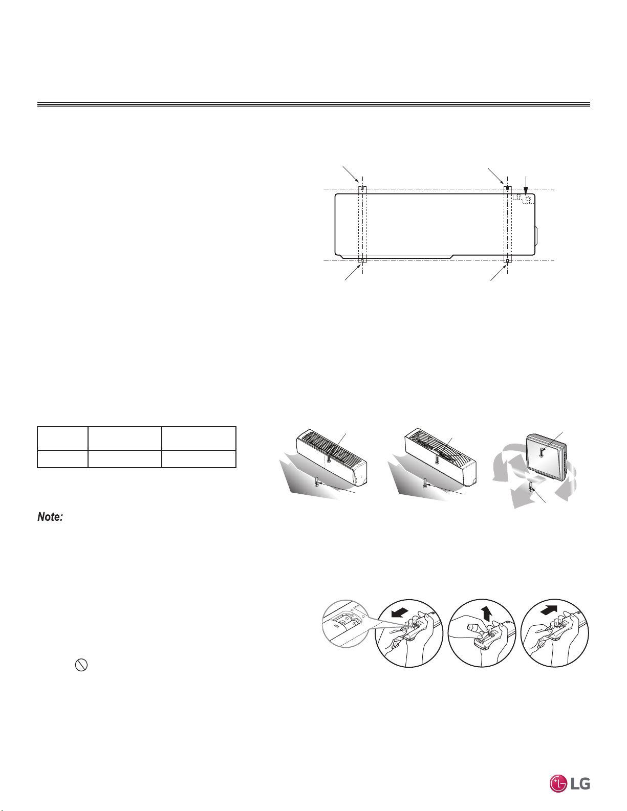
86
MULTI F / MULTI F MAX Outdoor Unit Installation Manual
Due to our policy of continuous product innovation, some specifications may change without notification.
©LG Electronics U.S.A., Inc., Englewood Cliffs, NJ. All rights reserved. “LG” is a registered trademark of LG Corp.
MULTI
F
MAX
MULTI
F
Test Run
After the triple leak / pressure and evacuation procedures are com-
plete, perform a test run.
Before the Test Run
1. Check that all condensate tubing, refrigerant piping and power
wiring, and communication / connection (power) cables are prop-
erly connected.
2. Make sure that the gas and liquid service valves are fully open.
Refrigerant
Type
Outside Ambient
Temperature
Gas Side Service
Valve Pressure
R410A ) 113~142 psig
If the pressure is >142 psig, the system is most likely overcharged, and refrigerant must be removed. If the pressure is <113 psig, the system is most
likely undercharged and refrigerant must be added.
Outlet
Temperature
Discharge Air
Inlet Temperature
Outlet
Temperature
Discharge Air
Inlet Temperature
Outlet
Temperature
Discharge Air
Inlet Temperature
Figure 110: Piping Connection on the Outdoor Unit (Will Differ Depend-
ing on Outdoor Unit Model).
Figure 111: Inlet and Outlet Temperature Locations on Various Indoor Units.
Installing the Remote Controller Batteries
As part of the test run, the batteries need to be inserted into the remote
controller, and the remote controller will need to be powered on to
operate the indoor units (depending on the indoor units included in the
system). To insert the batteries, follow the steps below. For information
on using the remote controller, refer to its owner’s manual.
1. The remote controller needs two (2) AAA (1.5V) batteries for oper-
ation.
Do not use rechargeable batteries. Remove the battery
cover from the back of the remote controller by pushing downward
on the tab at the top of the battery cover and then lift up to remove.
2. Insert the two new batteries. Align batteries by the (+) and (-) sides (the interior battery compartment of the remote controller will have
clear markings for the (+) and (-) placement).
3. Verify that the batteries have “clicked” into the compartment and are firmly engaged with the contacts on either side.
4. Reattach the back cover of the remote controller.
5. Proceed with powering on the remote controller and usage as needed.
Test Run Procedure
1. Operate the system in cooling mode for 15 to 20 minutes.
2. Evaluate performance as the system runs, verifying the outdoor unit, and all indoor units and branch distribution units (Multi F MAX sys-
tems only) are working properly. Make notes as needed to address any issues that might be found.
• Check the system refrigerant charge:
• Measure the pressure from the gas side service valve.
• Measure the indoor unit inlet and outlet air temperatures. Verify the difference between the intake temperature and the discharge is
PRUHWKDQ)
• See table below for the optimum condition of the gas side pressure (again, system is in cooling mode).
Figure 112: Installing the Remote Controller Batteries.
Table 38: Optimum Conditions of the Gas Side Pressure.
7HVW5XQ
FINAL INSTALLATION PROCEDURES
Bolt
Refrigerant Pipe
Connection Location
Top of Outdoor Unit
(Looking Down)
Bolt
Bolt
Bolt
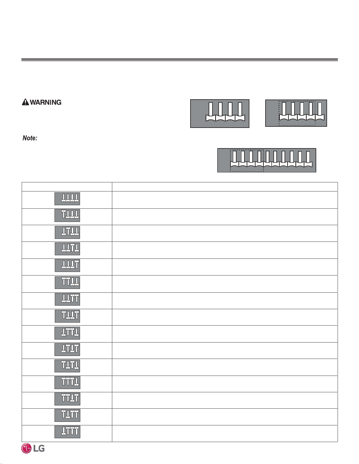
87
Final Installation Procedures
Due to our policy of continuous product innovation, some specifications may change without notification.
©LG Electronics U.S.A., Inc., Englewood Cliffs, NJ. All rights reserved. “LG” is a registered trademark of LG Corp.
MULTI
F
MAX
MULTI
F
Outdoor Unit DIP Switch Settings
System must be powered off, and then turned back on to apply DIP
switch settings.
Turn off the circuit breaker or shut off the power source of the product
before setting the DIP switch. There is risk of physical injury or death due
to electric shock.
• Unless the applicable DIP switch is set properly, the system will not work.
• ,IDVSHFL¿FIXQFWLRQLVGHVLUHGUHTXHVWWKDWWKHLQVWDOOHUVHWWKHDSSURSULDWH',3
switch during installation.
• 2QO\WKH¿UVWIRXU',3VZLWFKHVDUHXVHGWRVHWVHWWLQJVDQGIXQFWLRQV
',36ZLWFK6HWWLQJVIRU2SWLRQDO0RGHV
Table 39: DIP Switch Settings and Functionalities.
FINAL INSTALLATION PROCEDURES
12 43
12 43
ON
OFF
Figure 113: LMU18CHV~36CHV,
Outdoor Unit DIP Switches (in
Normal Operation Setting).
DIP Switch Setting Function
Normal Operation (No Function)
Forced Cooling Operation
Wiring Error Check
Reducing Power Consumption (Step 1)
Reducing Power Consumption (Step 2)
Mode Lock (Cooling)
Mode Lock (Heating)
Night Quiet Mode (Step 1)
Night Quiet Mode (Step 2)
Mode Lock (Cooling) + Night Quiet Mode (Step 1)
Mode Lock (Cooling) + Night Quiet Mode (Step 2)
Reducing Power Consumption (Step 1) with Mode Lock (Cooling)
Reducing Power Consumption (Step 2) with Mode Lock (Cooling)
Reducing Power Consumption (Step 1) with Mode Lock (Heating)
Reducing Power Consumption (Step 2) with Mode Lock (Heating)
12 43
12 43
ON
OFF
12 43
12 43
ON
OFF
12 43
12 43
ON
OFF
12 43
12 43
ON
OFF
12 43
12 43
ON
OFF
12 43
12 43
ON
OFF
12 43
12 43
ON
OFF
12 43
12 43
ON
OFF
12 43
12 43
ON
OFF
12 43
12 43
ON
OFF
12 43
12 43
ON
OFF
12 43
12 43
ON
OFF
12 43
12 43
ON
OFF
12 43
12 43
ON
OFF
12 43
12 43
ON
OFF
Figure 114: LMU180~240HV,
LMU480-540HV Outdoor Unit DIP
Switches (in Normal Operation
Setting).
Figure 115: LMU600HV Outdoor Unit DIP Switches (in Normal Opera-
tion Setting).
12 43
12 43
ON
OFF
5
5
12 43
12 43
ON
OFF
5
5
67 9810
678910
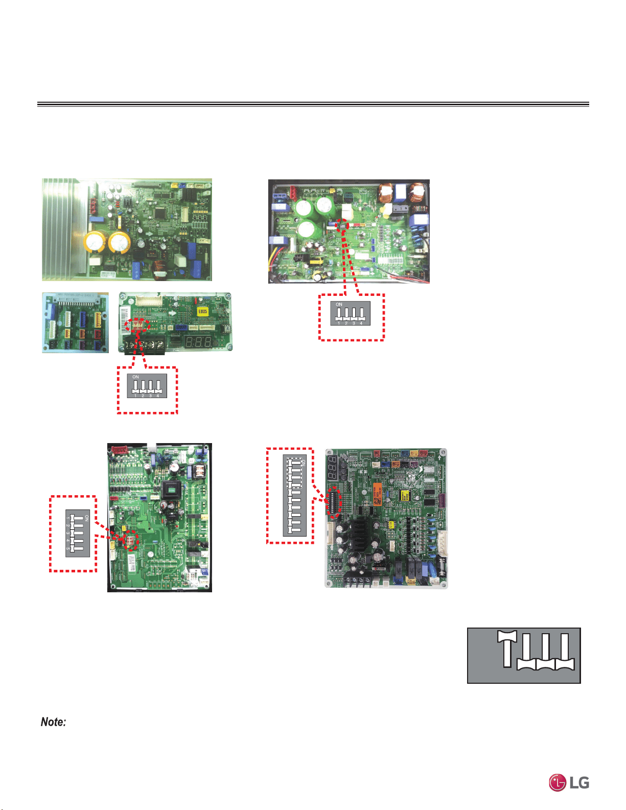
88
MULTI F / MULTI F MAX Outdoor Unit Installation Manual
Due to our policy of continuous product innovation, some specifications may change without notification.
©LG Electronics U.S.A., Inc., Englewood Cliffs, NJ. All rights reserved. “LG” is a registered trademark of LG Corp.
MULTI
F
MAX
MULTI
F
',36ZLWFK6HWWLQJVIRU2SWLRQDO0RGHV
FINAL INSTALLATION PROCEDURES
Forced Cooling Operation Function
Use to add refrigerant to the system when outside ambient temperatures are cool (ex.: winter).
1. Shut power down to the system.
2. Set DIP Switch 1 to ON.
3. Turn power on to the system.
4. Verify that the Red LED on the outdoor unit PCB is ON (indicates indoor units are in forced cooling
operation).
5. Add refrigerant.
• If the green LED light on the outdoor unit PCB is ON, it indicates the compressor is OFF due to low pressure in the system.
• Turn DIP Switch 1 to OFF after finishing (Normal Operation setting).
• Only the first four DIP switches are used to set settings and functions.
Multi F LMU18*HV and LMU24*HV
DI P- SW
SW01 N
DIP SW 2
Multi F LMU30CHV and LMU36CHV
Multi F MAX LMU480HV and LMU540HV
DIP-SW01D
12 34 5678910
Multi F MAX LMU600HV
Location of DIP Switches on Multi F and Multi F MAX Outdoor Units
Figure 116: Multi F / Multi F MAX Outdoor Unit DIP Switch Locations (WIll Vary in Appearance Depending on Model).
12 43
12 43
ON
OFF
Figure 117: Forced Cooling DIP
Switch Setting.

89
Final Installation Procedures
Due to our policy of continuous product innovation, some specifications may change without notification.
©LG Electronics U.S.A., Inc., Englewood Cliffs, NJ. All rights reserved. “LG” is a registered trademark of LG Corp.
MULTI
F
MAX
MULTI
F
',36ZLWFK6HWWLQJVIRU2SWLRQDO0RGHV
FINAL INSTALLATION PROCEDURES
Wiring Error Check
Use to verify if wiring is properly installed.
1. Shut power down to the system.
2. Set DIP Switch 2 to ON.
3. Turn power on to the system.
4. Check if the Red and Green LEDs on the outdoor unit PCB are ON (indicate indoor units are in forced
operation mode).
5. If the wiring is correctly installed, the Green LED will light up. If the wiring is incorrectly installed, the
Red and Green LEDs will blink, indicating which part of the system is in error.
• Red LED = Piping Number
• Green LED = Wiring Number (Room)
Example: If the Red LED blinks twice and the Green LED blinks three times, the second
piping to the third room is in error (see at right).
• If the indoor unit(s) are not communicating properly to the outdoor unit, the Wiring
Error Check cannot operate correctly.
• Only the part of the system in error will be displayed. System will operate correctly
after the error is fixed.
• If outdoor and indoor temperatures are too low (ex.: winter), the wiring error check function will not operate (Red LED is ON).
• Turn DIP Switch 2 to OFF after finishing (Normal Operation setting).
• Only the first four DIP switches are used to set settings and functions.
3
12 43
12 43
ON
OFF
Figure 118: Wiring Error Check
DIP Switch Setting.
One (1)
Second
LED 1
(Red)
LED 2
(Green)
Three (3)
Blinks
Two (2)
Blinks
One (1)
Second
One (1)
Second
One (1)
Second
Two (2)
Blinks
Three (3)
Blinks
Figure 119: Wiring Error Check Example.
Reducing Power Consumption
Enables more efficient system operation by reducing the maximum power consumption
value (reducing the MCA).
1. Shut power down to the system.
2. For Step 1, set only DIP Switch 3 to ON. For Step 2, set only DIP Switch 4 to ON.
3. Turn power on to the system.
Table 40: Reducing Power Consumption Current Levels.
Phase 1Ø
Model
Multi F
LMU18*HV,
LMU24*HV
Multi F
LMU30CHV,
LMU36CHV
Multi F MAX
LMU480HV,
LMU540HV,
LMU600HV
Step 1 (A) 91322
Step 2 (A) 81121
Power
Consumption
and Current
Normal
Time
Figure 120: Reducing Power Consumption Chart.
12 43
12 43
ON
OFF
12 43
12 43
ON
OFF
Step 1 Step 2
Figure 121: Reducing Power Consumption DIP Switch Settings.
• Reduced Power Consumption reduces outdoor unit capacity.
• 2QO\WKH¿UVWIRXU',3VZLWFKHVDUHXVHGWRVHWVHWWLQJVDQGIXQFWLRQV
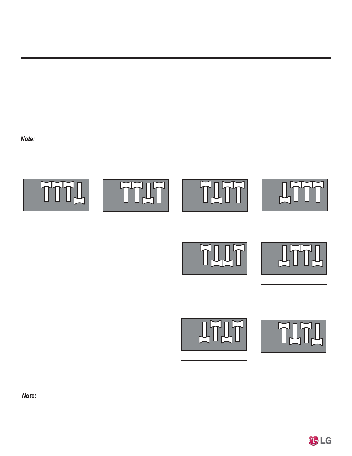
90
MULTI F / MULTI F MAX Outdoor Unit Installation Manual
Due to our policy of continuous product innovation, some specifications may change without notification.
©LG Electronics U.S.A., Inc., Englewood Cliffs, NJ. All rights reserved. “LG” is a registered trademark of LG Corp.
MULTI
F
MAX
MULTI
F
Reducing Power Consumption with Mode Lock
Enables more efficient system operation by lowering the maximum power consumption value, as well as locks the mode of operation (Exam-
ple: In a cooling-only server room application where permission to adjust the system mode is highly limited). Changing modes can cause a
change in compressor frequency, which would cause problems with the setting. As such, if this mode is used, it is locked in either cooling or
heating. The function is rarely, if ever, used.
1. Shut power down to the system.
2. Set DIP Switches as indicated below, following the steps and chosen mode.
3. Turn power on to the system.
',36ZLWFK6HWWLQJVIRU2SWLRQDO0RGHV
FINAL INSTALLATION PROCEDURES
Night Quiet Mode
Lowers the operation sound of the outdoor unit by changing the com-
pressor frequency and fan speeds. Night quiet mode initiates eight
(8) hours after the highest outdoor air temperature is measured, then
is active for nine (9) hours.
1. Shut power down to the system.
2. For Step 1, set only DIP Switches 2 and 3 to ON. For Step 2, set
only DIP Switches 1 and 4 to ON.
3. Turn power on to the system.
• If compressor frequency and fan speed are decreased, cooling capacity also will decrease accordingly.
• Night Quiet Mode can only be used when system is in cooling operation.
• Change the DIP switches if Night Quiet Mode is no longer desired.
• ,ILQGRRUXQLWRSHUDWLRQLVVHWE\WKHIDQVSHHG³3RZHU´1LJKW4XLHW0RGHZLOOQRWIXQFWLRQXQWLOIDQVSHHG³3RZHU´LVFKDQJHG
• Only the first four DIP switches are used to set settings and functions.
Figure 122: Saving Power Consumption with Mode Lock DIP Switch Settings.
Step 1: Reducing Saving Power Con-
sumption + Mode Lock (Cooling)
Step 2: Reducing Saving Power Consump-
tion + Mode Lock (Cooling)
Step 1: Reducing Saving Power Consump-
tion + Mode Lock (Heating)
Step 2: Reducing Saving Power Consump-
tion + Mode Lock (Heating)
Figure 123: Night Quiet Mode DIP Switch Settings.
Step 1 Step 2
Night Quiet Mode with Mode Lock
Lowers the operation sound of the outdoor unit by changing the
compressor frequency and fan speeds, as well as locks the mode of
operation. Changing modes can cause a change in compressor fre-
quency, which would cause problems with the setting. As such, if this
mode is used, it is locked in either cooling or heating. The function
is rarely, if ever, used. Night quiet mode initiates eight (8) hours after
the highest outdoor air temperature is measured, then is active for
nine (9) hours.
1. Shut power down to the system.
2. For Step 1, set only DIP Switches 2 and 4 to ON. For Step 2, set
DIP Switches 1 and 3 to ON.
3. Turn power on to the system.
Step 1: Night Quiet Mode + Mode Lock
(Cooling)
Step 2: Reducing Saving Power Consump-
tion + Mode Lock (Cooling)
Figure 124: Night Quiet Mode with Mode Lock DIP Switch Settings.
2QO\WKH¿UVWIRXU',3VZLWFKHVDUHXVHGWRVHWVHWWLQJVDQGIXQFWLRQV
12 43
12 43
ON
OFF
12 43
12 43
ON
OFF
12 43
12 43
ON
OFF
12 43
12 43
ON
OFF
12 43
12 43
ON
OFF
12 43
12 43
ON
OFF
12 43
12 43
ON
OFF
12 43
12 43
ON
OFF
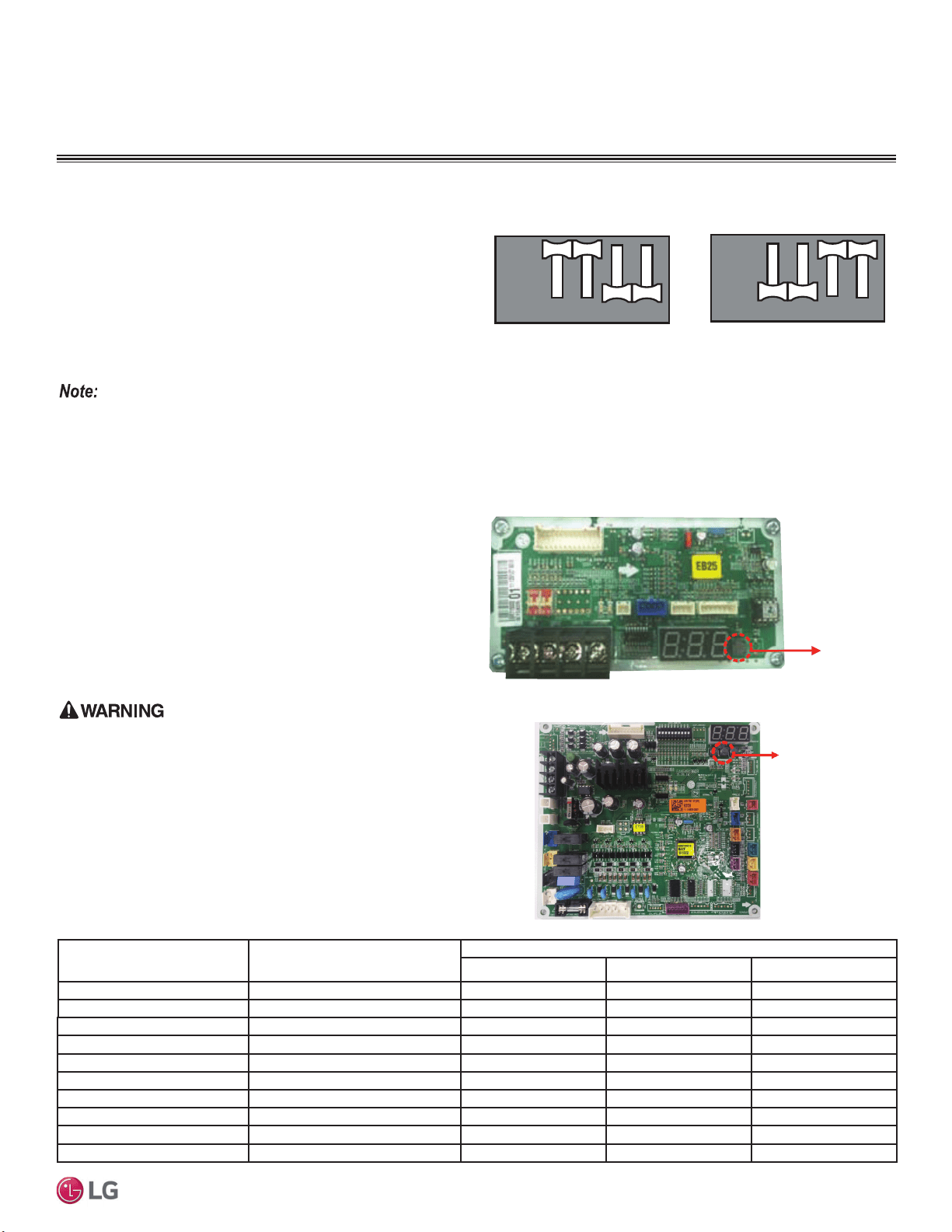
91
Final Installation Procedures
Due to our policy of continuous product innovation, some specifications may change without notification.
©LG Electronics U.S.A., Inc., Englewood Cliffs, NJ. All rights reserved. “LG” is a registered trademark of LG Corp.
MULTI
F
MAX
MULTI
F
FINAL INSTALLATION PROCEDURES
Mode Lock
Prevents mixed mode operation (mode change) in applications
where only one mode is necessary.
1. Shut power down to the system.
2. For Only Cooling Mode Lock, set only DIP Switches 1 and 2 to
ON. For Only Heating Mode Lock, set only DIP Switches 3 and 4
to ON.
3. Turn power on to the system.
Only Cooling Mode Lock Only Heating Mode Lock
Figure 125: Mode Lock DIP Switch Settings.
PCB Display (Multi F LMU18-24*HV
and LMU600HV Models Only)
For Multi F LMU18*HV, LMU24*HV, and LMU600HV outdoor units,
the cycle data can be checked without using LG Monitoring View
(LGMV) Diagnostic Software by pushing TACT-SW1. See below
for the types of cycle information that will be displayed in LGMV.
After first page is displayed, the second page will be subsequently
displayed.
3URWHFW¿QJHUVKDQGVZLWKDQRQFRQGXFWLQJPDWHULDOEHIRUHSXVKLQJ
TACT-SW1. There is risk of physical injury or death due to electric
shock.
TACT-SW1
No. of Pushes
Description
Display
Example First Page Second Page
One (1) Time Low Pressure 890kpa “LP” “89”
Two (2) Times High Pressure 2,900kpa “HP” “290”
Three (3) Times Discharge Temperature & “DS” “85”
Four (4) Times Condenser Outlet Temperature & “CS” “-10”
Five (5) Times Suction Temperature & “SS” “-10”
Six (6) Times Outdoor Unit Air Temperature & “AS” “-10”
Seven (7) Times Current 15A “A” “15”
Eight (8) Times Voltage 230V “V” “230”
Nine (9) Times Compressor Hz 100Hz “F” “100”
Ten (10) Times DC Link Voltage 230V “dc” “230”
Table 41: PCB Display Information.
TACT-SW1
Figure 126: Location of TACT-SW1 (LMU18-24*HV).
2QO\WKH¿UVWIRXU',3VZLWFKHVDUHXVHGWRVHWVHWWLQJVDQGIXQFWLRQV
Figure 127: Location of TACT-SW1 (LMU600HV).
TACT-SW1
12 43
12 43
ON
OFF
12 43
12 43
ON
OFF
',36ZLWFK6HWWLQJVIRU2SWLRQDO0RGHV
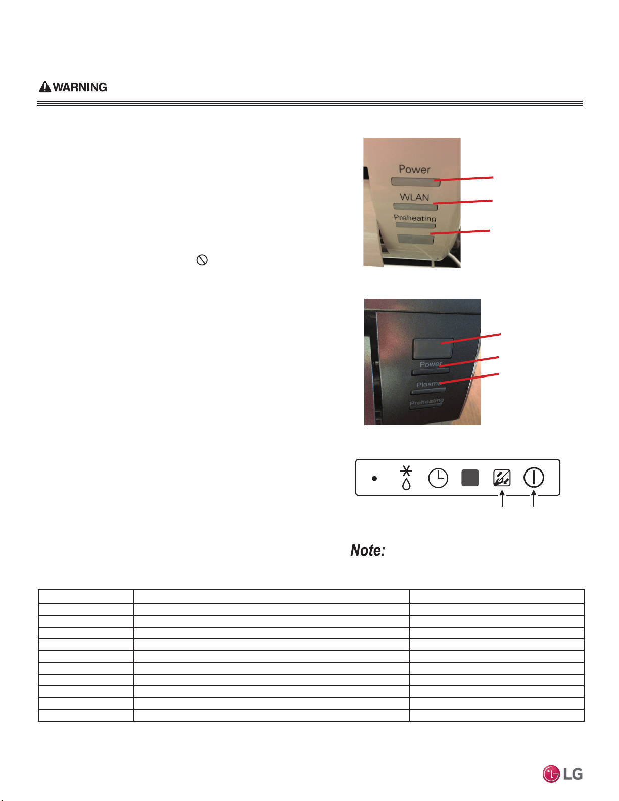
92
MULTI F / MULTI F MAX Outdoor Unit Installation Manual
Due to our policy of continuous product innovation, some specifications may change without notification.
©LG Electronics U.S.A., Inc., Englewood Cliffs, NJ. All rights reserved. “LG” is a registered trademark of LG Corp.
MULTI
F
MAX
MULTI
F
Error Code Description Indoor Unit Operation Status
00 No error ON
01 Indoor unit room temperature sensor error OFF
02 Indoor unit inlet pipe sensor error OFF
03 Controller error OFF
04 Drain pump error (optional) OFF
05 Communication error between indoor unit and outdoor units OFF
06 Indoor unit outlet pipe sensor error OFF
07 Different mode operation error OFF
09 Indoor unit EEPROM error OFF
10 Indoor unit BLDC motor fan lock OFF
Receiver
LED 1
(UNITS PLACE)
LED 2
(TENS PLACE)
Figure 128: Example of Standard Wall-Mounted Indoor Unit LEDs.
Figure 129: Example of Art Cool Mirror Wall-Mounted Indoor
Unit LEDs.
Number of Blinks = Error Code
LED 1: Units PlaceLED 2: Tens Place
Troubleshooting Using Error Codes
Refer to the tables below and on the next page for error codes
that are generated from the indoor and outdoor units. These codes
indicate different types of unit failures, assist in self-diagnosis, are
the most common that will manifest through these units. Error codes
are displayed on indoor unit LEDs, wired remote controllers, the
outdoor unit PCB, and through LG Monitoring View (LGMV) diagnos-
tic software.
Systems could generate additional codes not listed here. Contact LG
Support if these types of errors are seen and a simple power down
and boot up has not corrected the issue.
Do not attempt to fix
the system yourself.
• If two or more errors occur simultaneously, the highest error code
number is displayed first.
• After error is resolved, the error code does not display.
Decoding the Error Display
See images and table below for indoor unit error codes, location of
LEDs, and operation status.
The first and second number on the LED indicates error number. Ex-
ample: 21 = LED1 (Red light) 2x blink, LED2 (Green light) 1x blink.
Error Code Nomenclature Definitions
• MICOM: Non-volatile memory chip where unit setup information is
stored.
• EEPROM: Non-volatile memory chip where device identification,
size, and factory defined default component operating parameters
are stored.
Figure 130: Example of Ceiling Cassette Indoor Unit LEDs.
Table 42: Indoor Unit Error Codes.
ERROR CODE TABLES
LED 1
(UNITS PLACE)
LED 2
(TENS PLACE)
Receiver
Please refer to the Safety Precautions on pages 4-7 for more detail to prevent injury or death regarding the operation and
service troubleshooting of the Multi F / Multi F MAX product.
Appearances will vary depending on model.
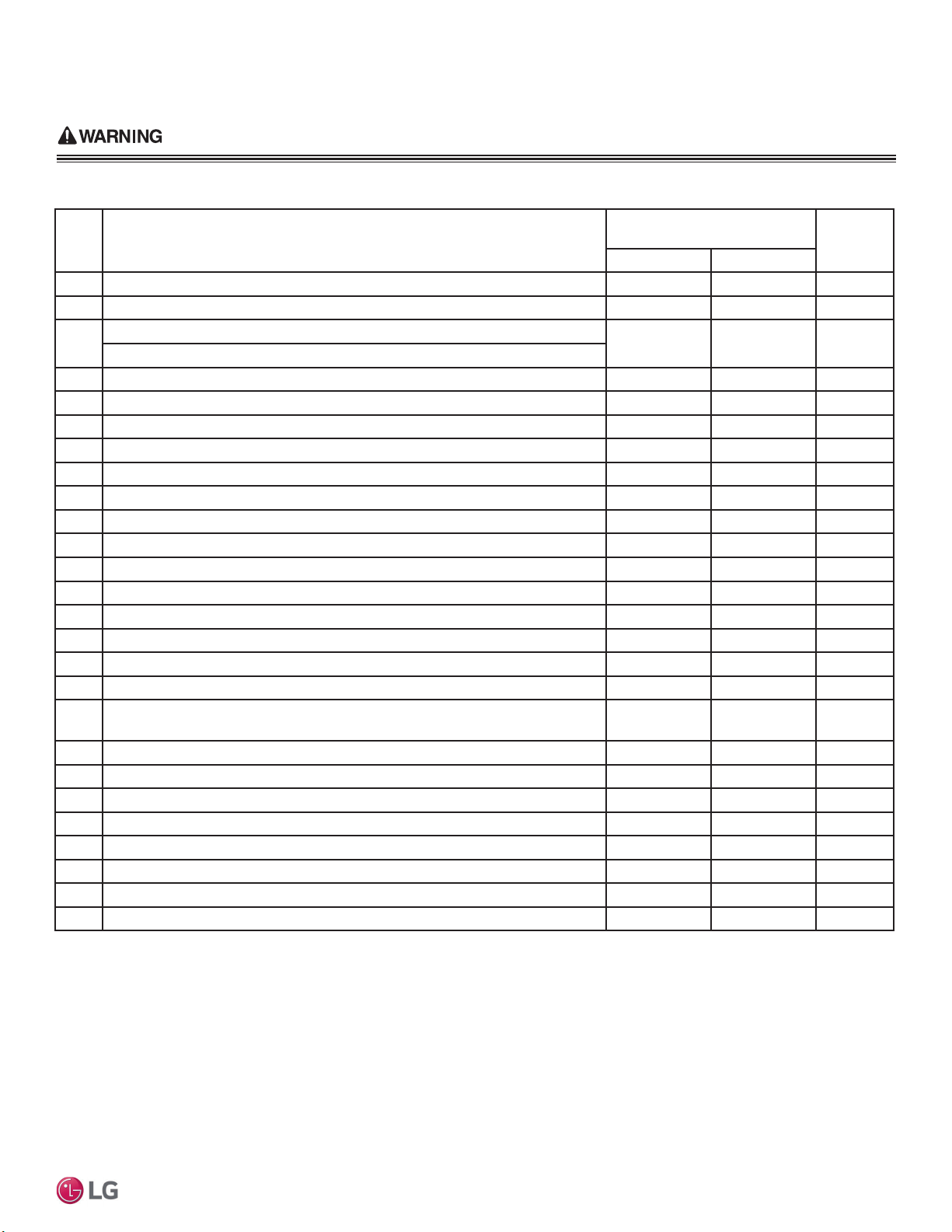
93
Error Codes
Due to our policy of continuous product innovation, some specifications may change without notification.
©LG Electronics U.S.A., Inc., Englewood Cliffs, NJ. All rights reserved. “LG” is a registered trademark of LG Corp.
MULTI
F
MAX
MULTI
F
Please refer to the Safety Precautions on pages 4-7 for more detail to prevent injury or death regarding the operation and
service troubleshooting of the Multi F / Multi F MAX product.
ERROR CODE TABLES
Error
Code
Description
No. of Times Outdoor Unit LEDs
Blink
Outdoor
Operation
Status
LED01 (Red) LED02 (Green)
21 DC Peak (IPM Fault); Compressor DC voltage was too high 2X 1X OFF
22 Current Transformer2 (CT2) error; Alternating current (AC) input too high 2X 2X OFF
23
DC Link Low Voltage (DC Link Voltage is <140VDC)
2X 3X OFF
DC Link High Voltage (DC Link Voltage is >420VDC)
25 AC Low / High Voltage 2X 5X OFF
26 DC Compressor Position Error (Compressor failed to start properly) 2X 6X OFF
27 PSC / PFC Fault; Input current to inverter compressor PCB is too high 2X 7X OFF
29 Current to inverter compressor is too high 2X 9X OFF
32 Inverter compressor discharge pipe (D-Pipe) temperature is too high 3X 2X OFF
35 Low Pressure Error; Pressure dropped below recommended limits 3X 5X OFF
39 Communication Error between PFC MICOM and Inverter MICOM 3X 9X OFF
40 CT Sensor Error; Thermistor is disconnected or has shorted out 4X - OFF
41 Inverter compressor discharge pipe (D-Pipe) sensor is disconnected or has shorted out 4X 1X OFF
43 High pressure sensor is disconnected or has shorted out 4X 3X OFF
44 Outdoor air sensor is disconnected or has shorted out 4X 4X OFF
45 Mid-pipe thermistor of outdoor unit condenser is disconnected or has shorted out 4X 5X OFF
46 Outdoor unit suction piping thermistor is disconnected or has shorted out 4X 6X OFF
48 Outlet piping (liquid) of condenser is disconnected or has shorted out 4X 8X OFF
51
Combination ratio (capacity) is out of range; Total nominal indoor unit capacity is<50%
or >130% of the outdoor unit capacity
5X 1X OFF
53 Communication failure between outdoor unit and indoor unit(s) 5X 3X OFF
54 Outdoor unit is not wired properly (ex: reversed phase) 5X 4X OFF
60 Outdoor unit printed circuit board (PCB) EEPROM check sum error 6X - OFF
61 Condenser coil thermistor temperature is too high 6X 1X OFF
62 Outdoor unit inverter compressor PCB heat sink temperature is too high 6X 2X OFF
65 Heat sink thermistor is disconnected or has shorted out 6X 5X OFF
67 Outdoor unit brushless direct current (BLDC) fan motor lock error 6X 7X OFF
73 Outdoor unit PFC overcurrent (peak) error 7X 3X OFF
Table 43: Outdoor Unit Error Codes.
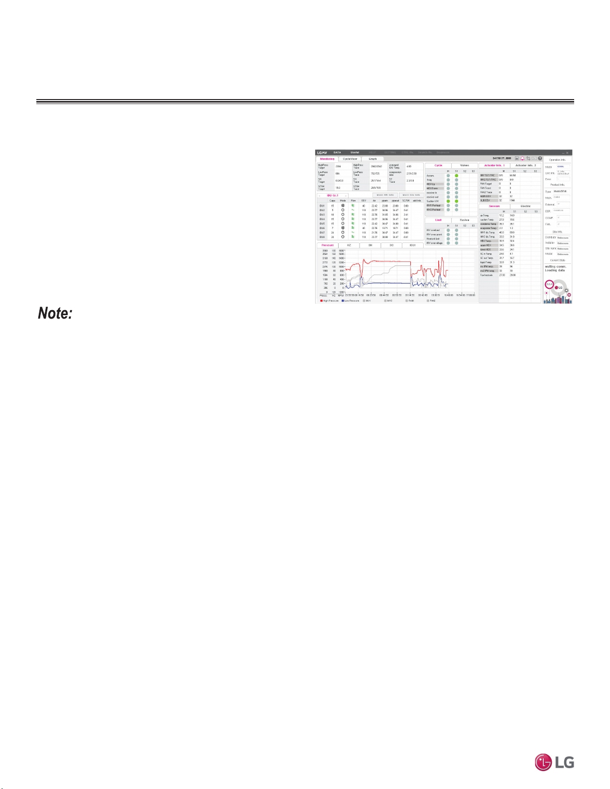
94
MULTI F / MULTI F MAX Outdoor Unit Installation Manual
Due to our policy of continuous product innovation, some specifications may change without notification.
©LG Electronics U.S.A., Inc., Englewood Cliffs, NJ. All rights reserved. “LG” is a registered trademark of LG Corp.
MULTI
F
MAX
MULTI
F
• Images on these pages are examples of LGMV screenshots. Actual images will differ depending on the version of the software and the units
installed.
• Information displayed also depends on which unit is installed.
LG Monitoring View (LGMV) Diagnostic Software
LG Monitoring View (LGMV) software allows the service technician
or commissioning agent to connect a computer USB port to the Multi
F / Multi F MAX system’s main printed circuit board (PCB) using an
accessory cable without the need for a separate interface device.
LGMV is available in different formats, including Mobile LGMV,
which is an app for use on wireless devices. Contact your LG Sales
Representative for more information, including recommended PC or
mobile device configurations.
LGMV Display
LGMV displays the following real-time data:
• Actual inverter compressor speed
• Target inverter compressor speed
• Actual outdoor fan speed
• Target outdoor unit fan speed
• Actual superheat
• Target superheat
• Actual subcooler circuit superheat
• Target subcooler circuit superheat
• Main EEV position
• Subcooling EEV position
• Inverter compressor current transducer value
• Outdoor air temperature
• Actual high pressure/saturation temperature
• Actual low pressure/saturation temperature
• Suction temperature
• Inverter compressor discharge temperature
• Constant speed compressor discharge temperature
• Front outdoor coil pipe temperature
• Back outdoor coil pipe temperature
• Liquid line pipe temperature
• Subcooler inlet temperature
• Subcooler outlet temperature
• Average indoor unit (IDU) pipe temperature
• Inverter compressor operation indicator light
• Four-way reversing valve operation
indicator light
• Pressure graph showing actual low pressure and actual high pres-
sure levels
• Error code display
• Operating mode indicator
• Target high pressure
• Target low pressure
• PCB (printed circuit board) version
• Software version
• Installer name
• Model no. of outdoor units
• Site name
• Total number of connected indoor units
• Communication indicator lights
• Indoor unit capacity
• Indoor unit operating mode
• Indoor unit fan speed
• Indoor unit EEV position
• Indoor unit room temperature
• Indoor unit inlet pipe temperature
• Indoor unit outlet pipe temperature
• Indoor unit error code
Figure 131: LGMV Monitoring Screen.
LG MONITORING VIEW (LGMV)
DIAGNOSTIC SOFTWARE
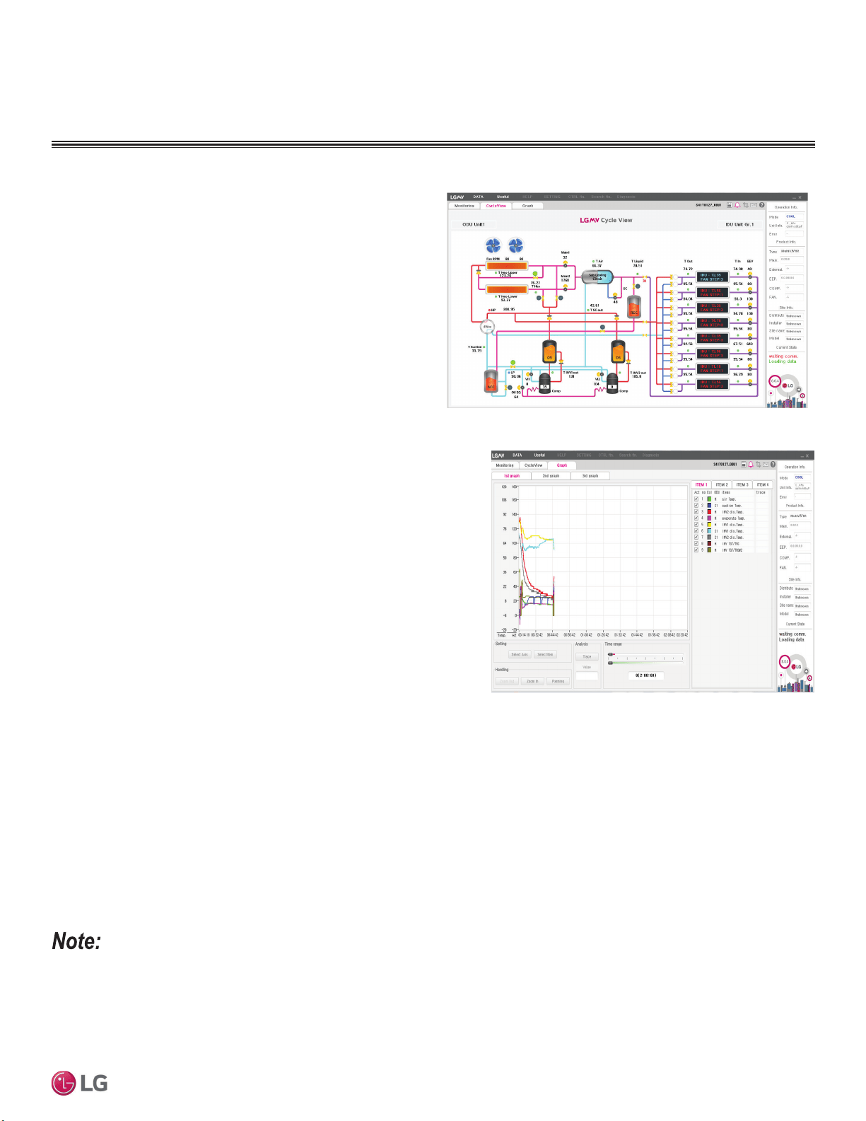
95
Error Codes
Due to our policy of continuous product innovation, some specifications may change without notification.
©LG Electronics U.S.A., Inc., Englewood Cliffs, NJ. All rights reserved. “LG” is a registered trademark of LG Corp.
MULTI
F
MAX
MULTI
F
• Inverter compressor
- Amps
- Volts
- Power Hz
- Inverter control board fan Hz
• Constant compressor
- Current transducer value
- Phase
Figure 132: LGMV Graph Screen.
Additional screens can be accessed by tabs on the main screen.
Additional screens include:
1. Cycleview: Graphic of internal components including:
• Compressors showing actual speeds
• EEVs
• Indoor units
• Liquid injection valves
• Temperature and pressure sensors
• Four-way reversing valve
• Outdoor fans showing status and speeds
2. Graph: Full screen graph of actual high and low pressures and
high and low pressure limits. A sliding bar allows viewing of
previously recorded data.
3. Control IDU: Enables user to turn on IDU’s default setpoints of
)LQKHDWPRGHRU)LQFRROPRGH
4. Setting: Converts metric values to imperial values.
5. Making Data: Recording of real time data to a separate file
created to be stored on the user’s computer.
6. Loading Data: Recorded data from a saved “.CSV” file can be
loaded to create an LGMV session.
7. Electrical Data: The Electric tab on the main screen is changed to
show the following:
Figure 133: LGMV Cycleview Screen.
LG MONITORING VIEW (LGMV)
DIAGNOSTIC SOFTWARE
• Images on these pages are examples of LGMV screenshots. Actual images will differ depending on the version of the software and the units
installed.
• Information displayed also depends on which unit is installed.
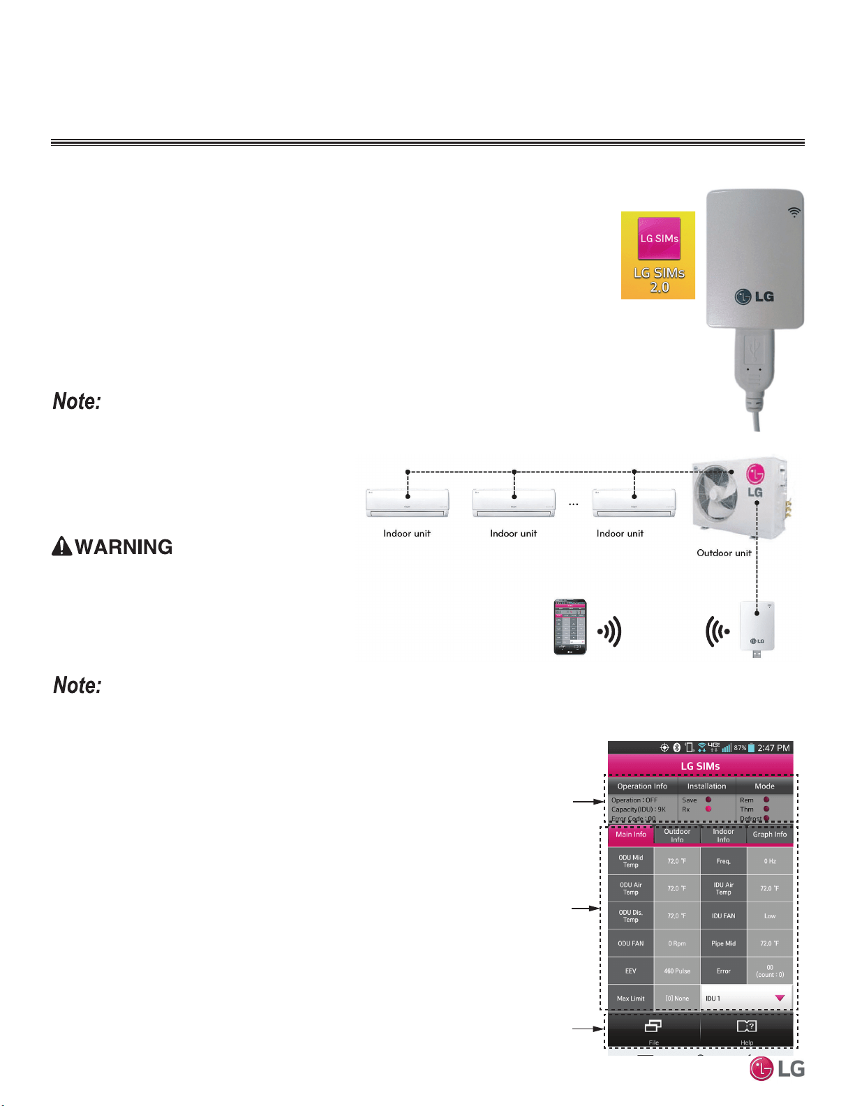
96
MULTI F / MULTI F MAX Outdoor Unit Installation Manual
Due to our policy of continuous product innovation, some specifications may change without notification.
©LG Electronics U.S.A., Inc., Englewood Cliffs, NJ. All rights reserved. “LG” is a registered trademark of LG Corp.
MULTI
F
MAX
MULTI
F
LG SMART INVERTER
MONITORING SYSTEM (SIMS)
LG SIMs
WLAN Module
LG SIMs App
on Smart Phone
LG SIMS
The LG Smart Inverter Monitoring System (SIMS) WLAN module and the smart phone app
together provide monitoring and troubleshooting capability for LG Multi F / Multi F MAX
systems. SIMS functions only with LG Duct Free products, and can also be used with Single
Zone one-to-one configurations such as the Single Zone Wall Mount systems.
SIMS can display and graph operational data for the air conditioner system including the
indoor unit and the outdoor unit. SIMS also displays error codes and a troubleshooting guide.
A full copy of the LG SIMS User’s Manual is available on the www.lghvac.com website.
To use SIMS you must be a trained HVAC service technician familiar with LG’s Duct Free
Systems. You must understand the inverter air conditioning operation cycle, the meaning of
the data displayed by SIMs, and how to use the data to troubleshoot the system.
• The Duct Free System air conditioning system must
run for at least 15–20 minutes before data collected
by SIMS 2.0 is valid for troubleshooting.
• The free SIMS app must be correctly installed on a
smart phone before using SIMS.
• Some outdoor units have an LGMV extension cable
accessed by removing the side handle cover. If the
outdoor unit does not have this extension cable, ac-
cess the LGMV connector by removing the top cover
of the outdoor unit.
High voltages capable of causing death are used in this
equipment. Outdoor unit power remains connected during
this procedure. Take extreme caution not to touch electri-
cal components or connections. Failure to observe this
warning can result in death or severe injury.
Figure 134: LG SIMS App and WLAN Module.
Figure 135: Example of a SIMS WLAN Module Used with a Typical DFS System.
Figure 136: SIMs App Main Info Screen.
SIMs App Main Info Screen
The main screen is the first screen displayed after wireless connection is
established. Tap the Main Info tab to display current readings regarding
your indoor and outdoor unit(s). The Operational Info area of the screen
will show active functions or modes by illuminating the light to the right of
the function.
Additional Help information can be accessed by tapping the Help Menu
buttons at the bottom of this screen.
Operational
Information
AC Cycle
Information on
Main Info Tab
Help Menu
(File is Factory Use Only)
• Images on these pages are examples of SIMS
screenshots. Actual images will differ depending on
the version of the software and the units installed.
• Information displayed also depends on which unit is
installed.
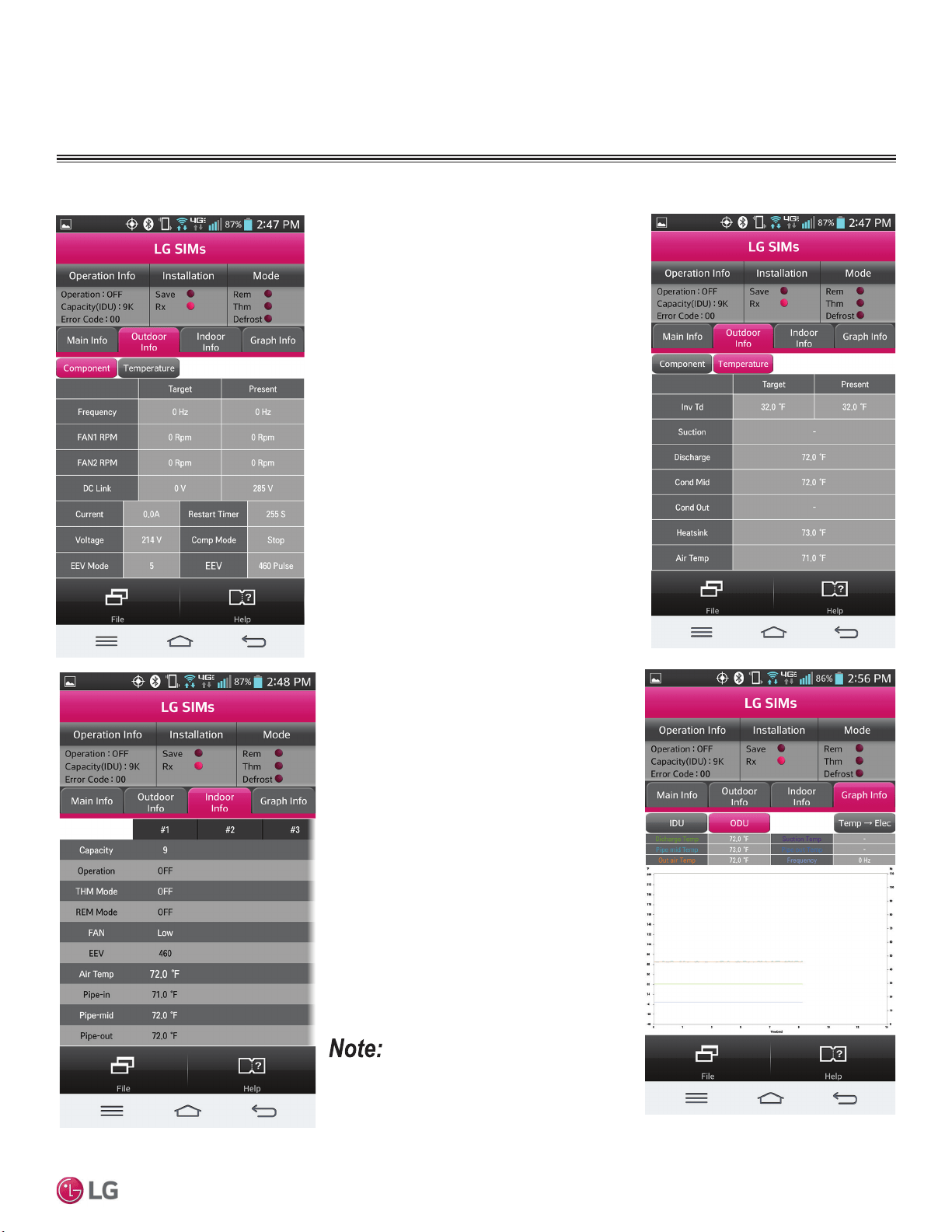
97
Error Codes
Due to our policy of continuous product innovation, some specifications may change without notification.
©LG Electronics U.S.A., Inc., Englewood Cliffs, NJ. All rights reserved. “LG” is a registered trademark of LG Corp.
MULTI
F
MAX
MULTI
F
SIMS App Screens
Outdoor Info /
Component Screen
Displays the following
information:
• Frequency
• FAN1 RPM
• FAN2 RPM
• DC Link
• Current
• Voltage
• EEV Mode
• Restart Timer
• Comp Mode
• EEV
Indoor Info Tab
Displays the following
information:
• Frequency
• Operation
• THM Mode
• REM Mode
• FAN
• EEV
• Air Temp
• Pipe-in
• Pipe-mid
• Pipe-out
Graph Info Tab
This tab, has three sub
sections:
• IDU - Indoor Unit
Temperature graph.
Displays IDU informa-
tion in graph format. In-
formation displayed is
for the IDU # selected
on the Main screen.
• ODU - Outdoor Unit
Temperature and Fre-
quency graph. Displays
ODU information in
graph format.
• ODU Electric - Out-
door Unit Electric data
graph is displayed.
Outdoor Info/
Temperature Screen
Displays the following
information:
• Inv TD
• Suction
• Discharge
• Cond Mid
• Cond Out
• Heatsink
• Air Temp
LG SMART INVERTER
MONITORING SYSTEM (SIMS)
• Images on these pages are examples of SIMS
screenshots. Actual images will differ depend-
ing on the version of the software and the units
installed.
• Information displayed also depends on which unit
is installed.
98
MULTI F / MULTI F MAX Outdoor Unit Installation Manual
Due to our policy of continuous product innovation, some specifications may change without notification.
©LG Electronics U.S.A., Inc., Englewood Cliffs, NJ. All rights reserved. “LG” is a registered trademark of LG Corp.
MULTI
F
MAX
MULTI
F
MAINTENANCE RECOMMENDATIONS
It is also recommended to monitor system operation using LGMV and / or SIMS Software at least once a year.
Table 44: Maintenance Recommendations.
Component Maintenance Occurrence (Minimum)
Indoor Units
Wash filters On a regular basis / as needed
Clean coils Once a year
Clean / check unit base pan Once a year
Outdoor Unit(s) Clean coils Once or twice a year
Communications Cable and Power Wiring
Verify that all cables and wiring are properly
connected
Once or twice a year
MULTI
F
MAX
MULTI
F
Due to our policy of continuous product innovation, some specifications may change without notification.
©LG Electronics U.S.A., Inc., Englewood Cliffs, NJ. All rights reserved. “LG” is a registered trademark of LG Corp.
INSTALLATION CHECKLIST
PAGE 1
Major Component Rough-In
Description Check
Multi F / Multi F MAX outdoor unit was connected properly per local code and the product installation procedures.
All literature and bagged accessories have been removed from the fan discharge (ducted and cassette model indoor units).
All indoor units and branch distribution unit(s) (Multi F MAX only) are installed, properly supported, and located indoors in a
non-corrosive environment.
Duct work installation completed (ducted indoor units only).
Piping Material, Components, and Insulation
Description Check
Multi-zone duct-free split systems: ACR copper piping rated at the system working pressure was used.
LG Y-branch fitting was used per manufacturer’s recommendations.
All refrigerant pipes and valves were insulated separately. Insulation is positioned up against the walls of the indoor units and
branch distribution units (Multi F MAX only). No gaps shown. Insulation was not compressed at clamps and hangers.
Brazing Practices
Description Check
Use medical grade dry nitrogen for purging during brazing (constant 3 psig while brazing).
15% silver brazing material only.
Refrigerant Piping Design and System
Description Check
You must have in your possession a copy of the “As-Designed” LATS Multi F piping tree diagram. BEFORE ANY FIELD PIPE SIZE
OR LENGTH CHANGES ARE MADE, PROPOSED CHANGES MUST BE FORWARDED TO THE DESIGN ENGINEER SO THAT
THEY CAN INPUT THE CHANGES INTO LATS and RE-ISSUE A NEW LATS MULTI F PIPING TREE DIAGRAM. Installer must
receive change authorization from the design engineer, because any change made requires the review of the entire tree diagram
and verification that the change did not impact the size of piping segments in other parts of the system.
All pipe materials were properly stored, capped, and clean. All burrs were removed after cutting and pipe ends were reamed
before brazing.
During refrigerant pipe installation, for each segment of pipe, a record was made of the pipe length (including expansion loops,
offsets, double-back sections), and sizes, as well as the quantity and type of elbows used.
Expansion loops, coils or other acceptable measures are provided where necessary to absorb temperature-change based pipe
movement.
A torque wrench and backup wrench were used to tighten all flare connections.
The back side of all flares were lubricated with a small drop of PVE refrigeration oil before tightening flare fittings.
(QVXUHDOOILHOGPDGHIODUHVDUH8VHIDFWRU\VXSSOLHGIODUHQXWVRQO\
Pipe segments and Y-branch fittings are secured to the structure using a combination of fixed and floating clamps, and all wall
penetrations were sleeved.
Pipe insulation was not compressed at any point.
Y-branch fittings were properly INSTALLED per details provided in the Multi F / Multi F MAX Outdoor Unit Installation Manual.
Y-branch fittings were properly SUPPORTED per details provided in the Multi F / Multi F MAX Outdoor Unit Installation Manual.
No oil traps, solenoid valves, sight glasses, filter driers, or any other unauthorized refrigerant specialties were present.
(Optional) High quality R-410A rated full port ball valves (Schrader between the valve body and the indoor units) used at all indoor
units and at will in the refrigerant piping network.
MULTI
F
MAX
MULTI
F
Due to our policy of continuous product innovation, some specifications may change without notification.
©LG Electronics U.S.A., Inc., Englewood Cliffs, NJ. All rights reserved. “LG” is a registered trademark of LG Corp.
INSTALLATION CHECKLIST
PAGE 2
Condensate Pump / Drain Installation
Description Check
Condensate piping installed correctly on indoor units. Material used is acceptable under local code. Insulated as necessary to
prevent condensation.
All condensate vertical risers are equal to or less 27-9/16 or 31-1/2 inches from the bottom of the indoor unit (depends on indoor
unit).
Indoor units with condensate pumps were level. Units with gravity drains were level or slightly canted toward the drain connection
and are supported properly.
Pumped condensate drain lines were properly connected (
do not have traps, and connect to the top surface of the main drain
line).
Multi F / Multi F MAX gravity condensate drain line was connected and routed where it properly drains away or, if installed in a
mechanical room, was connected and properly routed to a drain terminal.
All condensate lines were properly insulated to prevent condensation.
Power Wire and Communications Cables
Description Check
Ground wire was installed and properly terminated at the unit.
Power wiring was connected to a single phase 208-230V source.
The power supplied was clean with voltage fluctuations within specifications (±10% of nameplate).
Power wiring to the Multi F / Multi F MAX outdoor unit was field supplied, solid or stranded, and installed per all local, state, and
NEC requirements.
For Multi F Systems
• When the wiring length is up to 130 feet, communication / connection (power) wiring from the outdoor unit to the indoor unit is mini-
mum 14 gauge, four-conductor, stranded, shielded or unshielded. If shielded, must be grounded to chassis at the outdoor unit only.
• When the wiring length is GREATER THAN 130 feet, communication / connection (power) wiring from the outdoor unit to the
indoor unit is minimum 14 gauge, stranded, shielded or unshielded. If shielded, must be grounded to chassis at the outdoor unit
only. Use a two (2) conductor wire for power; use a two (2) conductor wire for communication / ground. Separate the power AT
LEAST two (2) inches away from the communication / ground wire.
For Multi F MAX Systems
All power wiring / communication cable to be minimum 14 AWG from the Multi F MAX outdoor unit to the BD unit stranded, shield-
ed or unshielded (if shielded, it must be grounded to the chassis of the outdoor unit only), and must comply with applicable local
and national codes.
• When the wiring length is up to 130 feet, communication / connection (power) wiring from the BD unit to the indoor unit is minimum
14 gauge, four-conductor, stranded, shielded or unshielded. If shielded, must be grounded to chassis at the outdoor unit only.
• When the wiring length is GREATER THAN 130 feet, communication / connection (power) wiring from the BD unit to the indoor
unit is minimum 14 gauge, stranded, shielded or unshielded. If shielded, must be grounded to chassis at the outdoor unit only.
Use a two (2) conductor wire for power; use a two (2) conductor wire for communication / ground. Separate the power AT LEAST
two (2) inches away from the communication / ground wire.
Power wiring to the outdoor unit and communication / connection (power) cable from the outdoor unit to the indoor units or branch
distribution units (Multi F MAX only) were separated per manufacturer’s guidelines. These cannot be run in the same conduit.
Communications / connection (power) cable were run in the same conduit (outdoor unit to indoor unit or branch distribution unit
[Multi F MAX only] as provided in the product installation manual.
Proper communications cable was used between each indoor unit and its zone controller where applicable. No cables were
spliced and no wire nuts are present.
Communication type RS-485–BUS type.
Used appropriate crimping tool to attach ring or fork terminals at all power wiring and control cable terminations.
Only LG-supplied Y-cables were used between grouped indoor units, if applicable.
MULTI
F
MAX
MULTI
F
Due to our policy of continuous product innovation, some specifications may change without notification.
©LG Electronics U.S.A., Inc., Englewood Cliffs, NJ. All rights reserved. “LG” is a registered trademark of LG Corp.
INSTALLATION CHECKLIST
PAGE 3
Major Component Rough-In
Piping and Insulation
Brazing Practices
MULTI
F
MAX
MULTI
F
Due to our policy of continuous product innovation, some specifications may change without notification.
©LG Electronics U.S.A., Inc., Englewood Cliffs, NJ. All rights reserved. “LG” is a registered trademark of LG Corp.
INSTALLATION CHECKLIST
PAGE 4
Installation—Refrigerant Piping
Installation—Branch Distribution Unit (Multi F MAX Systems Only)
,QVWDOODWLRQ²&RQGHQVDWH3XPS'UDLQ,QVWDOODWLRQ
Installation—Power Wire and Communications Cables
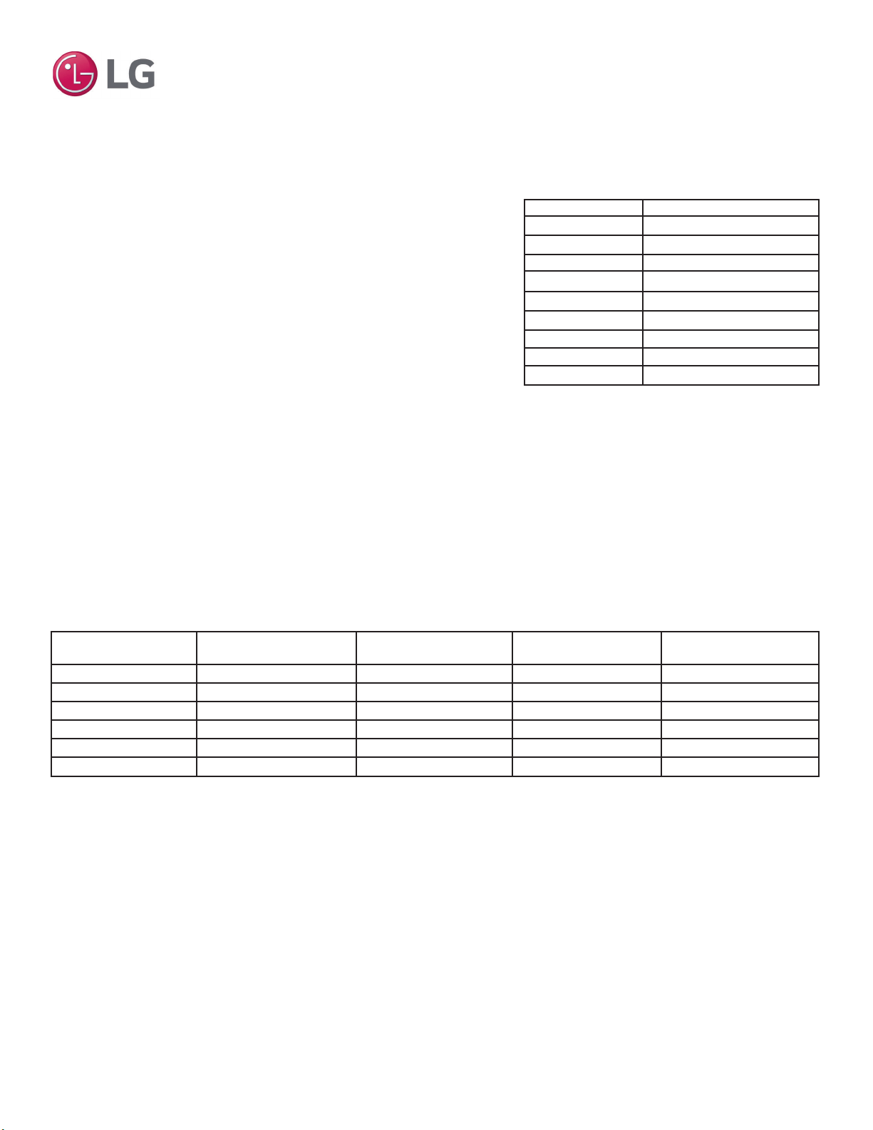
MULTI
F
MAX
MULTI
F
Due to our policy of continuous product innovation, some specifications may change without notification.
©LG Electronics U.S.A., Inc., Englewood Cliffs, NJ. All rights reserved. “LG” is a registered trademark of LG Corp.
MULTI F REFRIGERANT
CHARGE WORKSHEET
LG Multi F outdoor units ship from the factory with a charge of R410A refrigerant. A
trim charge will need to be added to take into account additional piping length.
To determine the additional refrigerant that is needed, apply the formula below,
and record the results. If the total additional refrigerant charge value is a negative
number, then an additional trim charge does not need to be added to the system.
Additional charge (lbs.) = (Installed Length of Branch [A] – Chargeless Pipe Length [L]) x a
+ (Installed Length of Branch [B] – Chargeless Pipe Length [L]) x a
+ (Installed Length of Branch [C] – Chargeless Pipe Length [L]) x a
+ (Installed Length of Branch [D] – Chargeless Pipe Length [L]) x a
- CF (Correction Factor) x 5.29
Multi F Outdoor Unit Factory Charge
• Number of installed length of branches depends on the specifications of the outdoor unit model.
• CF = Maximum number of connectible indoor units – Total number of connected indoor units.
Multi F Outdoor Unit Piping Specifications
(________[A] – 24.6) x 0.22 (________)
+ (________[B] – 24.6) x 0.22 + (________)
+ (________[C] – 24.6) x 0.22 + (________)
+ (________[D] – 24.6) x 0.22 + (________)
- ________CF x 5.29 - (________)
= ________ Additional Charge (oz.)
Multi F Refrigerant Charge Calculations
Multi F Outdoor Unit Additional Refrigerant Charge Formula
Note:
Multi F Outdoor Unit
Model
Min. to Max. Piping Length
for One Branch (ft.)
Max. Total System Piping
Length (ft.)
Chargeless Pipe Length
per Branch (L) (ft.)
Additional Charge Needed
(a) (oz./ft.)
LMU180HV 9.8 to 82 164 24.6 0.22
LMU18CHV 9.8 to 82 164 24.6 0.22
LMU240HV 9.8 to 82 230.0 24.6 0.22
LMU24CHV 9.8 to 82 246.1 24.6 0.22
LMU30CHV 9.8 to 82 246.1 24.6 0.22
LMU36CHV 9.8 to 82 246.1 24.6 0.22
Outdoor Unit Factory Charge lbs. of R410A
LMU180HV 3.97
LMU18CHV 3.96
LMU240HV 3.97
LMU24CHV 3.96
LMU30CHV 6.18
LMU36CHV 6.18
LMU480HV 9.7
LMU540HV 9.7
LMU600HV 12.3
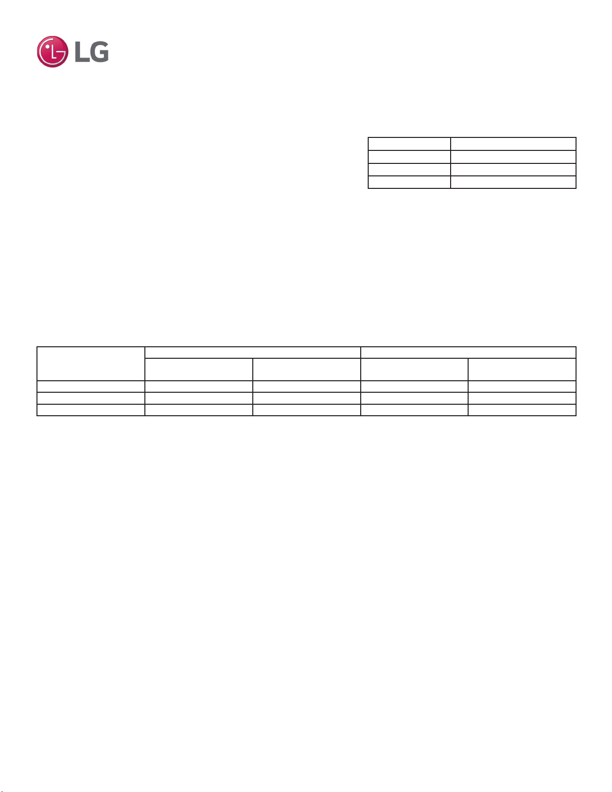
MULTI
F
MAX
MULTI
F
Due to our policy of continuous product innovation, some specifications may change without notification.
©LG Electronics U.S.A., Inc., Englewood Cliffs, NJ. All rights reserved. “LG” is a registered trademark of LG Corp.
Outdoor Unit Model
Main Piping Length Branch Piping Length
Chargeless Pipe Length of
Main Pipe (L) (ft.)
Additional Charge Needed
(a) (oz./ft.)
Chargeless Pipe Length
per Branch Pipe (B) (ft.)
Additional Charge Needed
(b) (oz./ft.)
LMU480HV 16.4 0.54 16.4 0.22
LMU540HV 16.4 0.54 16.4 0.22
LMU600HV 16.4 0.54 16.4 0.22
Multi F MAX Outdoor Unit Piping Specifications
Additional charge (lbs.) = (Total Main Piping Length [A] - Chargeless Pipe Length of Main Pipe [L]) x a
+ (Installed Length of Branch [B1] – Chargeless Pipe Length [B]) x b
+ (Installed Length of Branch [B2] – Chargeless Pipe Length [B]) x b
+ (Installed Length of Branch [B3] – Chargeless Pipe Length [B]) x b ...
- CF (Correction Factor) x 3.53
• Number of installed length of branches depends on system specifications.
• CF = Maximum number of connectible indoor units – Total number of connected indoor units
MULTI F MAX REFRIGERANT
CHARGE WORKSHEET
LG Multi F MAX outdoor units ship from the factory with a charge of R410A refrig-
erant. A trim charge will need to be added to take into account additional piping
length.
To determine the additional refrigerant that is needed, apply the formula below,
and record the results. If the total additional refrigerant charge value is a negative
number, then an additional trim charge does not need to be added to the system.
Outdoor Unit Factory Charge lbs. of R410A
LMU480HV 9.7
LMU540HV 9.7
LMU600HV 12.3
Multi F MAX Outdoor Unit Factory Charge
(________[A] – 16.4) x 0.54 (________)
+ (________[B1] – 16.4) x 0.22 + (________)
+ (________[B2] – 16.4) x 0.22 + (________)
+ (________[B3] – 16.4) x 0.22 + (________)
+ (________[B4] – 16.4) x 0.22 + (________)
+ (________[B5] – 16.4) x 0.22 + (________)
+ (________[B6] – 16.4) x 0.22 + (________)
+ (________[B7] – 16.4) x 0.22 + (________)
+ (________[B8] – 16.4) x 0.22 + (________)
- ________CF x 3.53 - (________)
= ________ Additional Charge (oz.)
Multi F MAX Refrigerant Charge Calculations
Note:
20001747 ISO 9001: 2008
LG ELECTRONICS INC.
LG Electronics, U.S.A., Inc.
Air Conditioning Technologies
4300 North Point Parkway
Alpharetta, Georgia 30022
www.lghvac.com
IM_MultiF_ODU_02_21
Supersedes: IM_MultiF_ODU_09_20
IM_MultiF_ODU_06_20
IM_MultiF_ODU_04_20
IM_MultiF_ODU_03_17
IM_MultiF_ODU_11_16
IM_MultiF_ODU_4_16
IM_MultiF_ODU_11_15