Loading ...
Loading ...
Loading ...
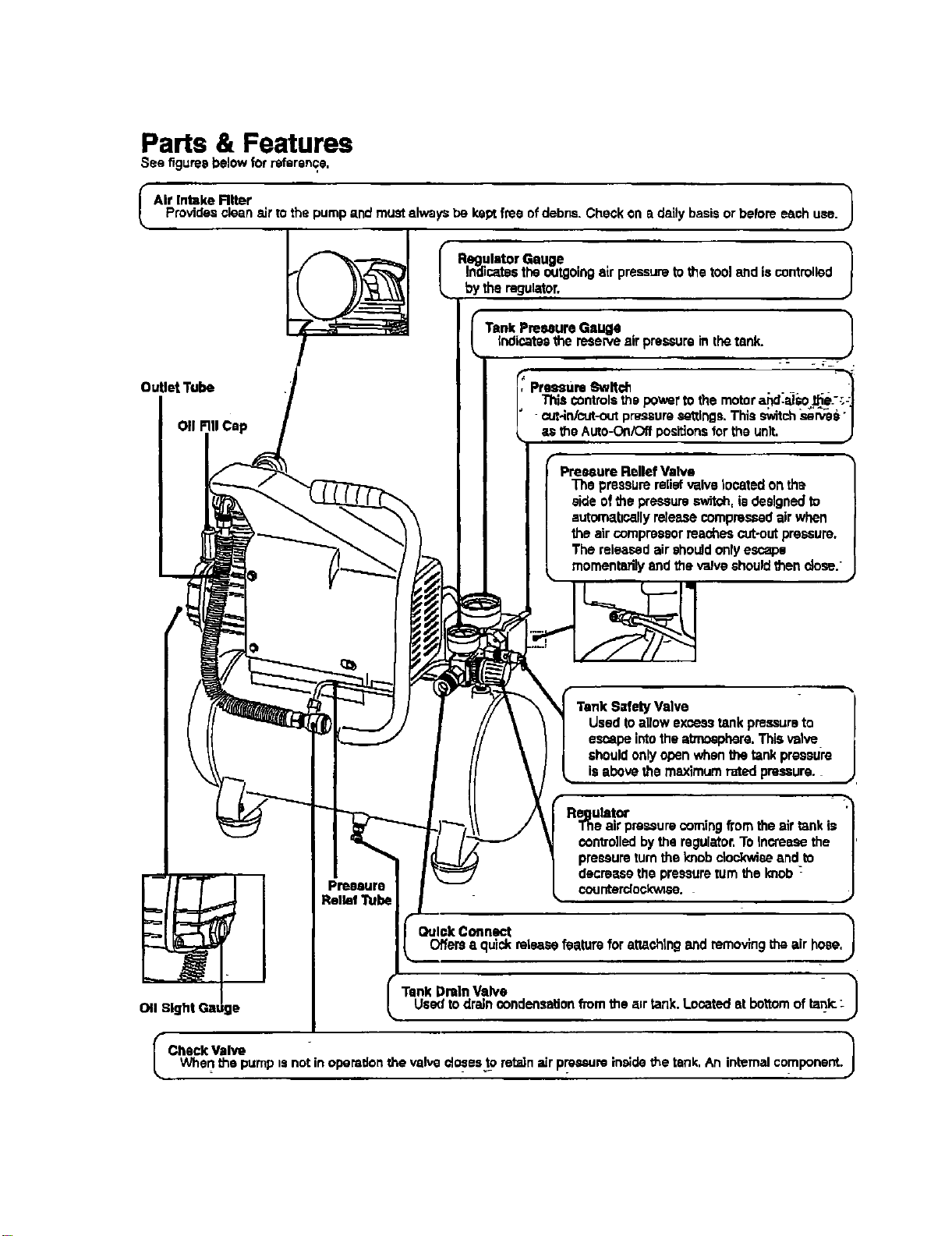
Parts & Features
See figuresbelowfor reference,
I AW Intake Rlter 1
Providesclean elf to the pump and must always be kept free of debris. Check on a daily basis or beforeeach use.
OutletTube
on FillCap
Regulator Gauge 1
Indicatesthe outgoingair pressureto the tooland is controlled
by the regulator.
Tank Preemui'eGauge |
indicatesthe reserve air pressure in thetank.
- _ 7- .
Pressure 8wlt_ . . _
This controlsthe powerto the motor aJ_d.al_e.--'.:_
cut4n/cut-outpressuresettings.This switch.served"1
the AkRo-OniOffpositionsfor the unit, J
=Valve
The pressurerelief valve located on the
side ofthe pressureswitch, is designedto
automa,bcallyrelease compressedair when
the air compressorreaches cut-outpressure,
The released air shouJdonly escape
momentarilyand the valve shouldthen dose.
t Valve
Used to allow excesstank pressureto
e_pe intothe atmosphere, This valve
should onlyopen when the tankpreastJre
is above the maximum rated pressure.
Regutatcr '_
The air pressurecomingfrom the air tank is |
con_olled by the regulator,To increasu the |
pressureturnthe le_obclePJxwieeand to |
decrease the pressureturn the knob _ |
Pressure counterdockw;su.
J
Relief Tube
Quick Connect 1Offers• quickrelease feature for sttashtngand removingthe air hose,
l Tank DraIn Valve 1
011Sight Gatiga Used to drsJnoundensation from the a=rtank, Located st bottom of tank.:
I Check valv_ 1
When the pump isnot in operationthe valve €losests retzdn=drpressure in,;de the tank, An internal component.
Loading ...
Loading ...
Loading ...