Loading ...
Loading ...
Loading ...
SECTION3: ASSEMBLINGYOURLAWNMOWER
ToRemoveUnit FromCarton
Remove staples, break glue on top flaps, or cut tape
at carton end and peel along top flap to open carton.
Remove loose parts included with your unit (i.e.,
operator's manual, etc.).
Cut along corners and lay carton down flat.
Remove packing material.
Roll or slide unit out of carton.
HardwarePack
1. Carriage Bolt 1/4-20 x.75" (2)
2. Wing Nut with Bell Washer (2)
ToolsRequired
1. Pair of Pliers
2. Funnel
NOTE: Reference to right or left hand side of the mower
is observed from the operating position.
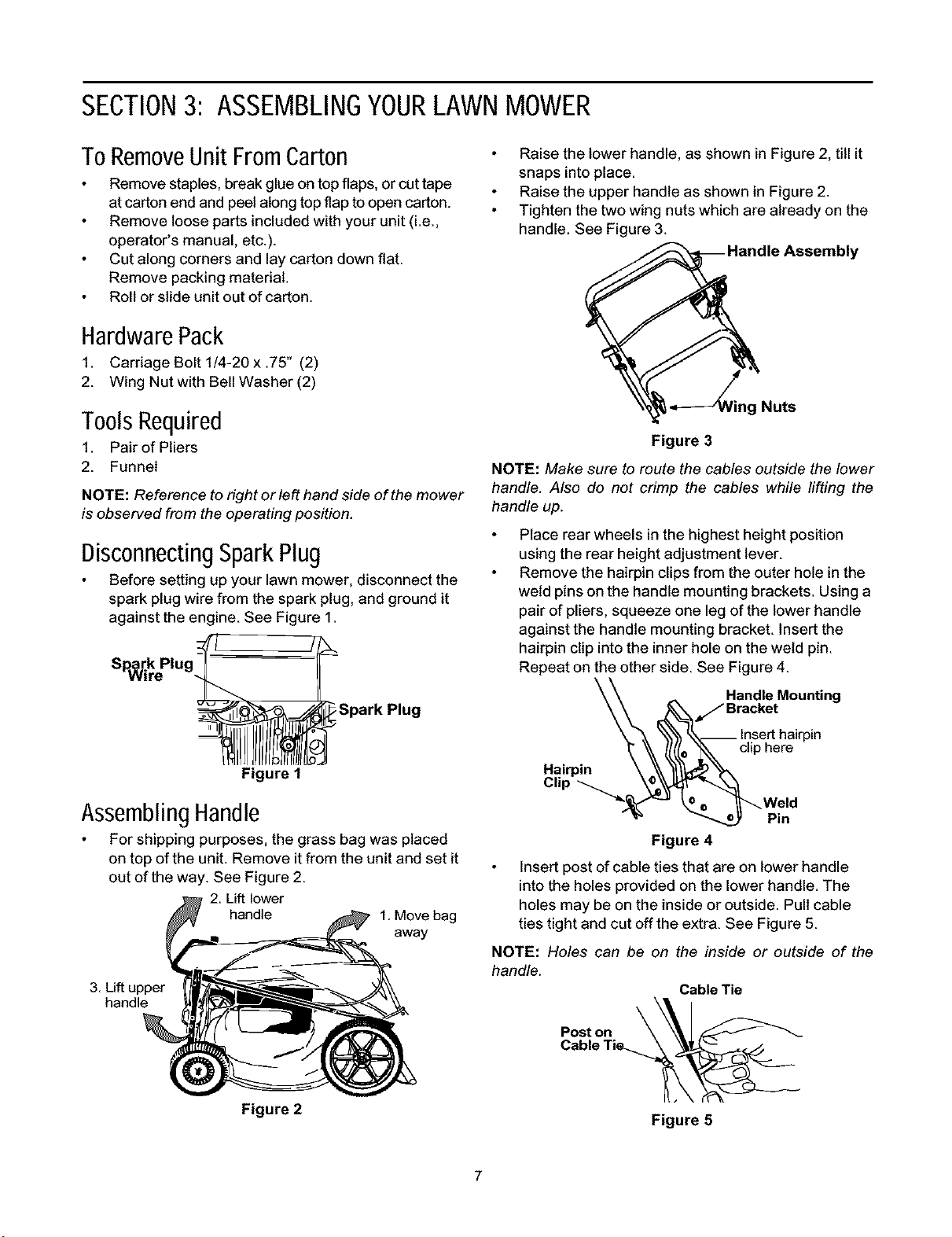
DisconnectingSparkPlug
Before setting up your lawn mower, disconnect the
spark plug wire from the spark plug, and ground it
against the engine. See Figure 1.
_-Spark Plug
Figure I
AssemblingHandle
For shipping purposes, the grass bag was placed
on top of the unit. Remove it from the unit and set it
out of the way. See Figure 2.
2. Lift lower
handle 1.Move bag
away
3. Liftupper
handle
Raise the lower handle, as shown in Figure 2, till it
snaps into place.
Raise the upper handle as shown in Figure 2.
Tighten the two wing nuts which are already on the
handle. See Figure 3.
Assembly
Nuts
Figure 3
NOTE: Make sure to route the cables outside the lower
handle. Also de not crimp the cables while lifting the
handle up.
Place rear wheels in the highest height position
using the rear height adjustment lever.
Remove the hairpin clips from the outer hole in the
weld pins on the handle mounting brackets. Using a
pair of pliers, squeeze one leg of the lower handle
against the handle mounting bracket. Insert the
hairpin clip into the inner hole on the weld pin.
Repeat on the other side. See Figure 4.
_, _, Handle Mounting
F_----_/Bracket
\\'_'hk,_,_ Insert hairpin
"_ _ ((((e"_ clip here
Hairpin \ \\ "ll\_
"_'_'J _© _'_ Weld
_ Pin
Figure 4
Insert post ofcable ties that are on lower handle
intothe holes provided on the lower handle. The
holes may be on the inside or outside. Pull cable
ties tight and cutoff the extra. See Figure 5.
NOTE: Holes can be on the inside or outside of the
handle.
Cable Tie
Post on
Figure 2
Figure 5
7
Loading ...
Loading ...
Loading ...