Loading ...
Loading ...
Loading ...
Place the new blade on the blade adapter with the
side marked bottom (or with part number) facing
away from the adapter.
Secure the blade to the assembly with two hex
bolts and lock nuts. Tighten the hex bolts to the
recommended torque. Refer to 'Blade Mounting
Torque' section on this page.
Install the blade assembly on the crankshaft. See
Figure 17. Secure with the hex bolt and bell washer
(cupped side of washer to blade) and tighten to the
recommended torque. Refer to 'Blade Mounting
Torque' section on this page.
IMPORTANT:The bolt, used to secure the blade to the
engine, is specially heat-treated. Do not substitute. To
order replacement bolt, refer to the parts list in the back
of this manual.
_lb WARNING: TO ensure safe operation ofyour lawn mower, check all nuts and bolts
periodically and tighten if necessary,
To Sharpen Blade:
The blade can be sharpened with a file or on a
grinding wheel. Do not attempt to sharpen the
blade while it is still on the mower.
Follow the original angle of grind as a guide. Make
sure that each cutting edge receives an equal
amount of grinding to prevent an unbalanced blade.
NOTE: An unbalanced blade will cause excessive
vibration when rotating at high speeds, may cause
damage to the mower and could break, causing
personal injury.
The blade can be tested by balancing it on a round
shaft screwdriver. See Figure 18. Remove metal
from the heavy side until it balances evenly. It is
recommended that the blade always be removed
from the adapter for the best test of balance.
1.Insert screw driver through hole
d.-"
2. Blade should be parallel to ground
Screw
Driver _ Blade
I o' o I
Ground
Figure 18
Blade Mounting Torque:
Blade adapter bolts: 120 in.tbs, minimum, 150 in.lbs.
maximum.
Center bolt: 450 in.lbs, minimum, 600 in.lbs, maximum.
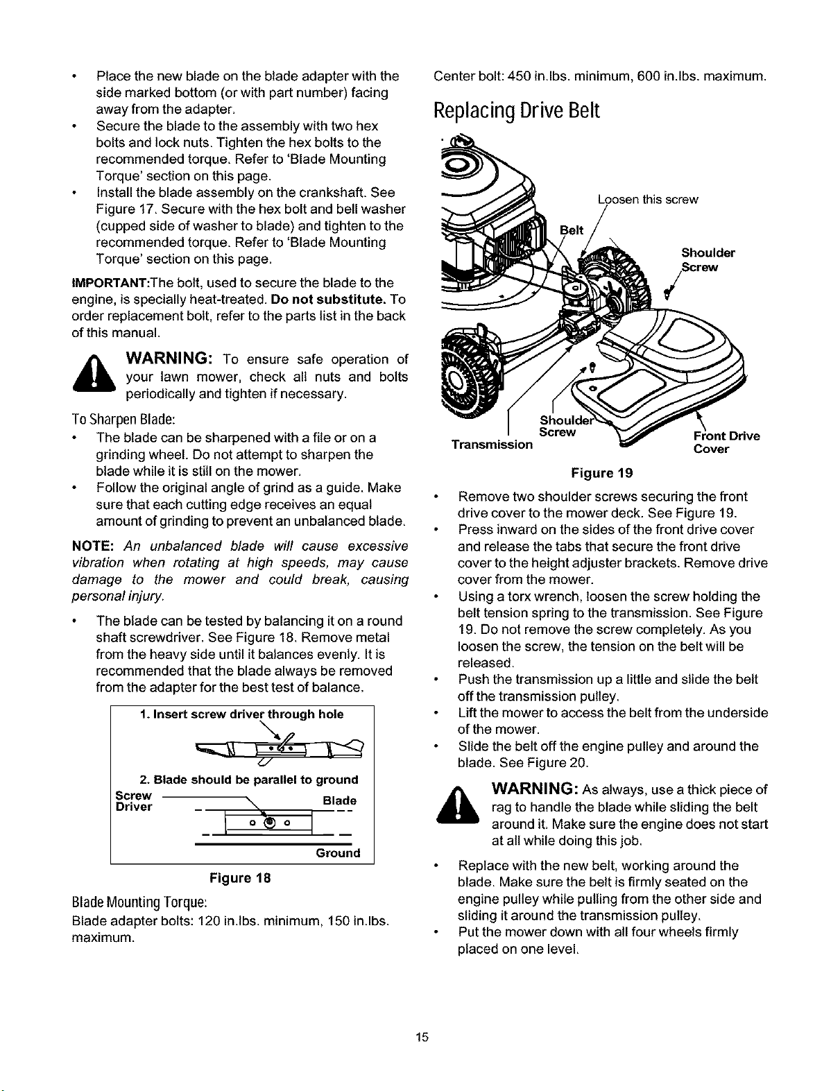
Replacing Drive Belt
Loosen this screw
Shoulder
Screw
Screw
Transmission
Cover
Figure 19
Remove two shoulder screws securing the front
drive cover to the mower deck. See Figure 19.
Press inward on the sides of the front drive cover
and release the tabs that secure the front drive
cover tothe height adjuster brackets. Remove drive
cover from the mower.
Using a torx wrench, loosen the screw holding the
belt tension spring to the transmission. See Figure
19. Do not remove the screw completely. As you
loosen the screw, the tension on the belt will be
released.
Push the transmission up a little and slide the belt
off the transmission pulley.
Lift the mower to access the belt from the underside
of the mower.
Slide the belt off the engine pulley and around the
blade. See Figure 20.
WARNING: As always, use a thick piece of
rag to handle the blade while sliding the belt
around it. Make sure the engine does not start
at all while doing this job.
Replace with the new belt, working around the
blade. Make sure the belt is firmly seated on the
engine pulley while pulling from the other side and
sliding itaround the transmission pulley.
Put the mower down with all four wheels firmly
placed on one level.
15
Loading ...
Loading ...
Loading ...