LGB
Boiler Manual
s)NSTALLATION
s3TARTUP
s-AINTENANCE
s0ARTS
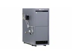
Series 2
Gas–Fired Boiler
Refer to
Control Supplement
for additional information
Read all instructions before installing
Installer Leave all instructions with boiler for future reference.
Any claims for damage or shortage in shipment must be filed immediately
against the transportation company by the consignee.
Owner Installation and service should be performed by qualified contractor.
Part No. 550-141-186/0914
Part Number 550-141-186/0914
2
LGB
3ERIES'AS&IRED"OILER"OILER-ANUAL
Do not use petroleum-based cleaning or sealing compounds in boiler
system. Severe damage to system components can result, causing substantial
property damage.
Read all instructions before installing. Failure to follow all instructions in
proper order can cause severe personal injury, death or substantial property
damage.
Hazard
The following defined terms are used throughout this manual to bring attention to the presence
of hazards of various risk levels, or to important information concerning the life of the product.
Indicates presence of hazards that will cause severe personal injury, death
or substantial property damage.
Indicates presence of hazards that can cause severe personal injury, death
or substantial property damage.
Indicates presence of hazards that will or can cause minor personal injury
or property damage.
Indicates special instructions on installation, operation or maintenance
that are important but not related to personal injury or property damage.
When calling or writing about the boiler— Please have the boiler model
number from the boiler rating label and the CP number from the boiler
jacket. You may list the CP number in the space provided on the
Installation
and service certificate
found on page 27.
The boiler contains ceramic fiber and fiberglass materials. Use care when
handling these materials per instructions on page 28 of this manual. Failure
to comply could result in severe personal injury.
Glycol — potential fire hazard —
All glycol is flammable when exposed to high temperatures. If glycol is
allowed to accumulate in or around the boiler or any other potential ignition
source, a fire can develop. In order to prevent potential severe personal injury,
death or substantial property damage from fire and/or structural damage:
s .EVERSTOREGLYCOLOFANYKINDNEARTHEBOILERORANYPOTENTIALIGNITION
source.
s -ONITORANDINSPECTTHESYSTEMANDBOILERREGULARLYFORLEAKAGE2EPAIR
any leaks immediately to prevent possible accumulation of glycol.
s .EVERUSEAUTOMOTIVEANTIFREEZEORETHYLENEGLYCOLINTHESYSTEM5SING
these glycols can lead to hazardous leakage of glycol in the boiler system.

Part Number 550-141-186/0914
3
s)NSTALLATIONs3TART5Ps-AINTENANCEs0ARTS
Codes .......................................................................................... 4
Air openings ............................................................................... 4
Venting ....................................................................................... 6
Foundation ................................................................................. 8
Base ........................................................................................... 9
Sections .................................................................................... 10
Hydrostatic pressure test ......................................................... 12
Cleanout plates ........................................................................ 14
Flue collector hood .................................................................. 15
Water boilers ............................................................................ 16
Steam boilers ........................................................................... 18
Multiple steam boilers ............................................................. 20
............................................................................................... 21
....................................................................................... 21
...................................................................... 22
Water boilers ............................................................................ 24
Steam boilers ........................................................................... 25
............................................................. 26
! ...................................................................... 27
" .................................................................................... 28
# .......................................................................... 32
...................................................................................... 34
$%&and ............................................ 35
# ............................................................................................. 36
' ...............................................(See Control Supplement)
( ......................................................(See Control Supplement)
1
2
3
4
5
6
7
8
9
10
11
12
13
14
Contents
Part Number 550-141-186/0914
4
LGB
3ERIES'AS&IRED"OILER"OILER-ANUAL
)NSTALLATIONSMUSTCOMPLYWITHALLLOCALCODESLAWSREGULATIONSANDORDINANCESALSO.ATIONAL
&UEL'AS#ODE!.3):nLATESTEDITION7HEN REQUIRED INSTALLATIONS MUST CONFORMTO
3TANDARDFOR#ONTROLSAND3AFETY$EVICESFOR!UTOMATICALLY&IRED"OILERS!.3)!3-%#3$
Safe lighting and other performance criteria were met with the gas manifold and control
ASSEMBLYPROVIDEDONBOILER WHEN BOILER UNDERWENTTESTSSPECIlED IN!.3) :nLATEST
edition.
#ANADIANINSTALLATIONSMUSTCOMPLYWITH#!.#3!"OR")NSTALLATION#ODE4HE
EQUIPMENTSHALLBEINSTALLEDINACCORDANCEWITHTHOSEINSTALLATIONREGULATIONSINFORCEINTHE
local area where the installation is to be made. These shall be carefully followed in all cases.
Authorities having jurisdiction shall be consulted before installations are made.
!
!
)
Combustion air and ventilation openings must comply with Section 5.3, Air for Combustion and
6ENTILATIONOF.ATIONAL&UEL'AS#ODE!.3):nLATESTEDITIONORAPPLICABLELOCALBUILDING
CODES#ANADIANINSTALLATIONSMUSTCOMPLYWITH#!.#3!"OR")NSTALLATION#ODE
Boiler installation must assure sufficient openings in building and boiler room to provide
ADEQUATECOMBUSTIONAIRANDVENTILATION#ONSIDERCONSTRUCTIONTIGHTNESSOFBUILDINGWHEN
deciding whether additional outside openings may be needed.
Older buildings with single-pane window, minimal weather-stripping and no vapor barrier
often provide enough natural infiltration and ventilation without dedicated openings.
.EWCONSTRUCTIONORREMODELEDBUILDINGSAREMOSTOFTENBUILTTIGHTER7INDOWSANDDOORSARE
weather-stripped, vapor barriers are used and openings in walls are caulked. As a result, such
tight construction is unlikely to allow proper natural air infiltration and ventilation.
Air from inside building (boiler in interior room):
Air openings
Pre-installation — air openings
1a
!DEQUATECOMBUSTIONAIRANDVENTILATIONOPENINGSMUSTBEPROVIDEDTO
assure proper combustion, prevent possibility of flue gas spillage and carbon
monoxide emissions, causing severe personal injury or death.
*
Boiler room
below grade
+
Boiler room
partially or
completely
above grade
Part Number 550-141-186/0914
5
s)NSTALLATIONs3TART5Ps-AINTENANCEs0ARTS
!
)
(continued)
s 4IGHTLYCONSTRUCTEDBUILDINGSMUSTBEPROVIDEDWITHOPENINGSTOOUTSIDEFORCOMBUSTION
and ventilation air. These openings must be sized to handle all fuel-burning appliances,
exhaust and ventilation fans and fireplaces.
s 7HENOPENINGSTOBOILERROOMARETAKENTOINTERIORSPACESPROVIDETWOPERMANENTOPEN-
INGSACOMBUSTIONAIROPENINGWITHININCHESOFmOORANDAVENTILATIONOPENINGWITHIN
INCHESOFCEILING%ACHOPENINGMUSTPROVIDEAMINIMUMFREEAREAOFONESQUAREINCH
PER"TUHINPUTOFALLAPPLIANCESINROOMPLUSREQUIREMENTSFORANYEXHAUSTFANSIN
ROOM4HEINTERIORSPACESUPPLYINGCOMBUSTIONANDVENTILATIONAIRMUSTHAVEADEQUATE
infiltration from outside.
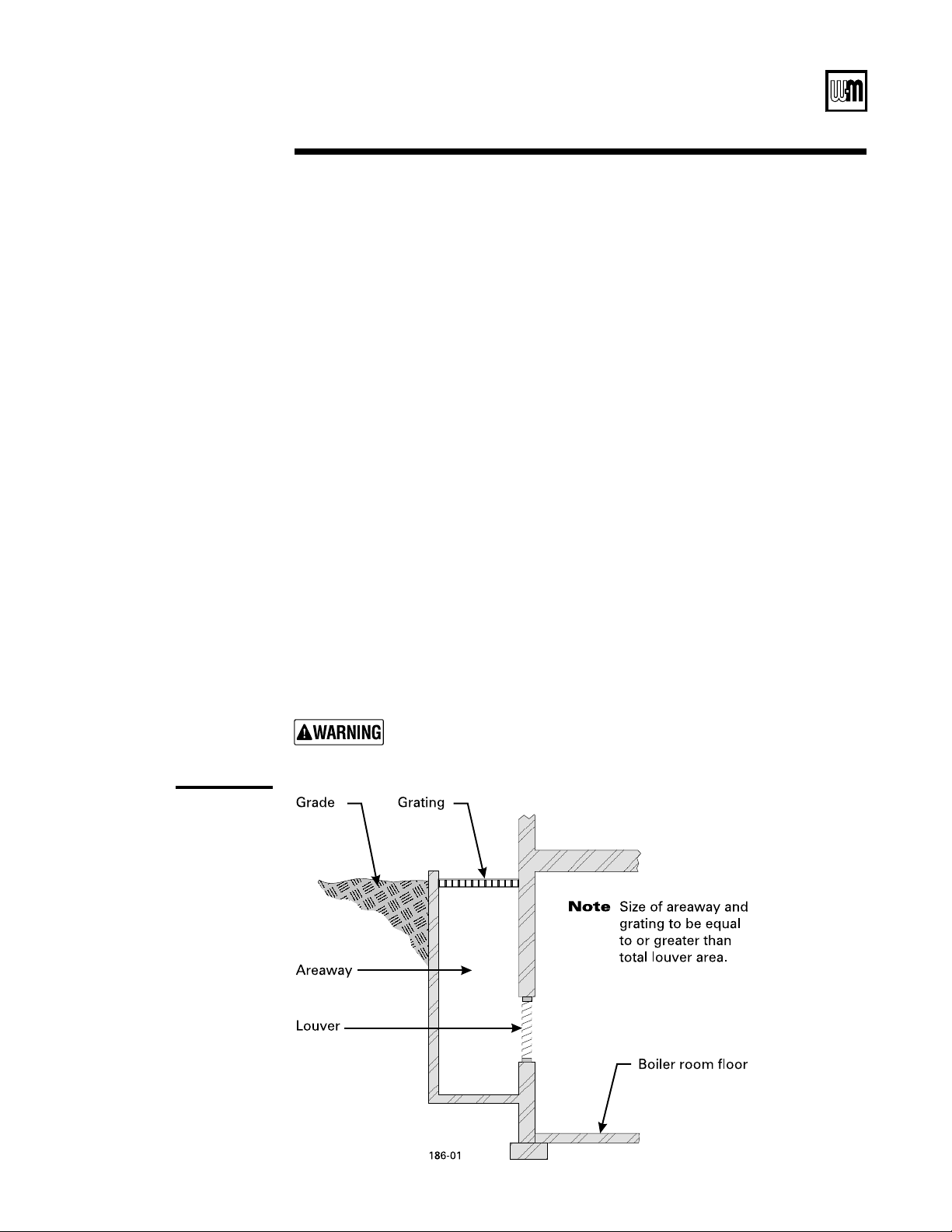
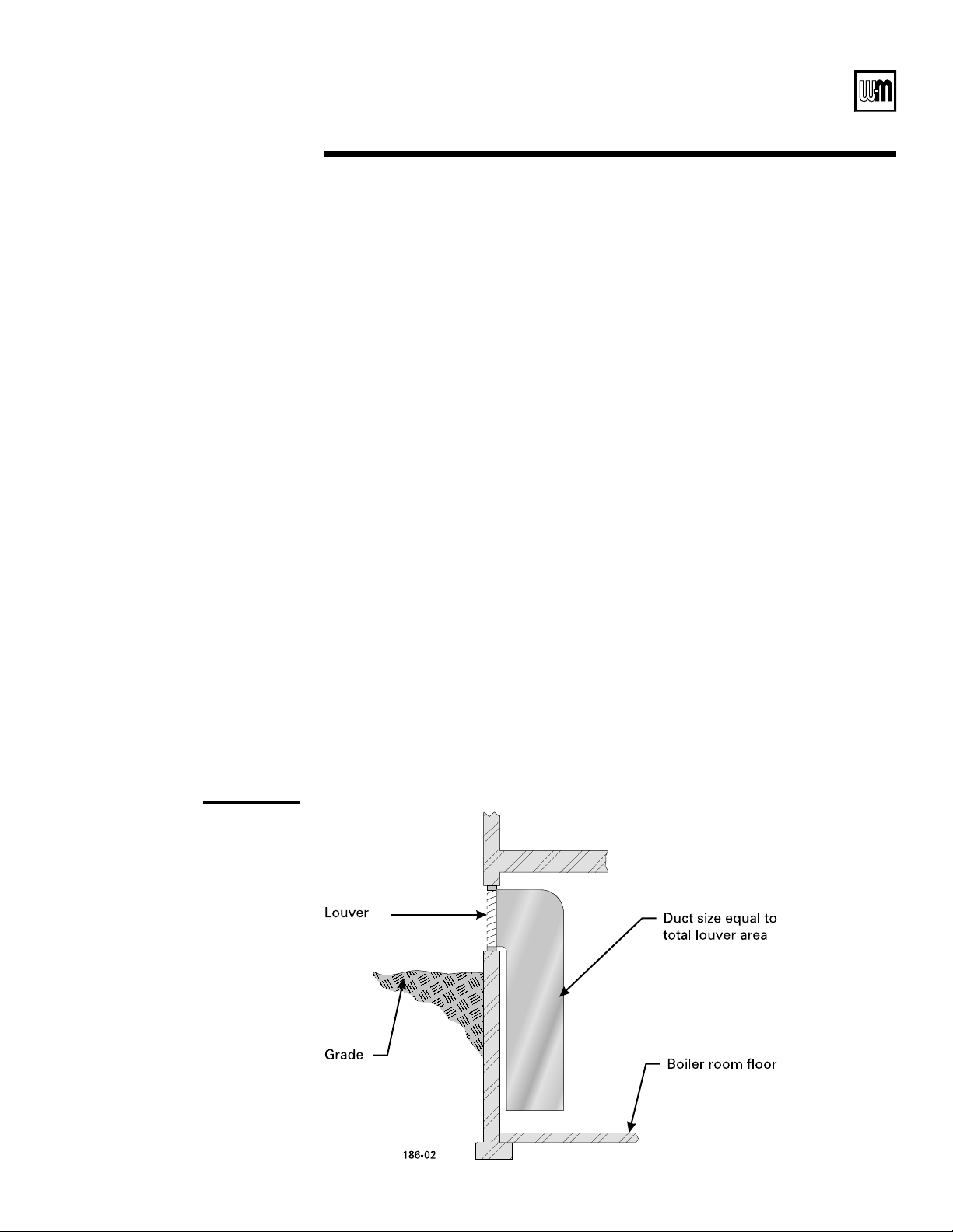
Air directly from outside to boiler room:
s 4IGHTLYCONSTRUCTEDBUILDINGSMUSTBEPROVIDEDWITH COMBUSTIONAIRAND VENTILATION
OPENINGSTOBOILERROOMWHICHAREADEQUATETOHANDLETHEBOILERNEEDSPLUSTHENEEDSOF
all other fuel-burning appliances, fireplaces and exhaust or ventilation fans.
s #OMBUSTIONANDVENTILATIONOPENINGSCONNECTINGDIRECTLYORBYDUCTINGTOOUTSIDEORTO
attic or crawl spaces that freely connect with outside, must be sized as follows:
/UTSIDEWALLORVERTICALDUCTINGONESQUAREINCHPER"TUHINPUTOFALLAPPLI-
ANCESINROOMPLUSREQUIREMENTSFORANYEXHAUSTFANSOROTHERAPPLIANCESINROOM
(ORIZONTALDUCTINGONESQUAREINCHPER"TUHOFALLAPPLIANCESINROOMPLUS
REQUIREMENTSFORANYEXHAUSTFANSOROTHERAPPLIANCESINROOM
!LLDUCTINGMUSTBESAMESIZEASPERMANENTOPENINGS-INIMUMAREADIMENSIONSOF
DUCTINGMUSTBENOLESSTHANSQUAREINCHES
4. Other size ducting must comply with local codes.
Compensate for louver blockage when calculating combustion air and ventilation openings.
See
Figures 1 and 2. Refer to manufacturer’s instructions for sizing.
Adjustable louvers must be locked open and combustion air damper must interlock with boiler
controls to open automatically before boiler operation.

Part Number 550-141-186/0914
6
LGB
3ERIES'AS&IRED"OILER"OILER-ANUAL
!,
()
)
6ENTINGMUSTBEINSTALLEDACCORDINGTO0ART6ENTINGOF%QUIPMENTOF.ATIONAL&UEL'AS
#ODE!.3):nLATESTEDITIONANDAPPLICABLEBUILDINGCODES#ANADIANINSTALLATIONSMUST
COMPLYWITH#!.#3!"OR")NSTALLATION#ODE
Breeching must not be connected to any portion of mechanical draft system that can operate
under positive pressure.
At the time of removal of an existing boiler, the following steps shall be followed with each
appliance remaining connected to the common venting system placed in operation, while the
other appliances remaining connected to the common venting system are not in operation.
a. Seal any unused openings in the common venting system.
b. Visually inspect the venting system for proper size and horizontal pitch and determine
there is no blockage or restriction, leakage, corrosion and other deficiencies which could
cause an unsafe condition.
c. Insofar as is practical, close all building doors and windows and all doors between the space
in which the appliances remaining connected to the common venting system are located
and other spaces of the building. Turn on clothes dryers and any appliance not connected to
the common venting system. Turn on any exhaust fans, such as range hoods and bathroom
exhausts, so they will operate at maximum speed. Do not operate a summer exhaust fan.
Close fireplace dampers.
d. Place in operation the appliance being inspected. Follow the lighting instructions. Adjust
thermostat so appliance will operate continuously.
e. Test for spillage at the draft hood relief opening after 5 minutes of main burner operation.
Use the flame of a match or candle.
f. After it has been determined that each appliance remaining connected to the common vent-
ing system properly vents when tested as outlined above, return doors, windows, exhaust
fans, fireplace dampers, and any other gas-burning appliance to their previous conditions
of use.
g. Any improper operation of the common venting system should be corrected so the instal-
LATIONCONFORMSTOTHE.ATIONAL&UEL'AS#ODE!.3):nLATESTEDITION7HENRESIZING
any portion of the common venting system, the common venting system should be resized
to approach the minimum size as determined using the appropriate tables in Appendix G
INTHE.ATIONAL&UEL'AS#ODE!.3):nLATESTEDITION
#ANADIANINSTALLATIONSMUSTCOMPLYTO#!.#3!"OR")NSTALLATION#ODES
Flue gas spillage
1b
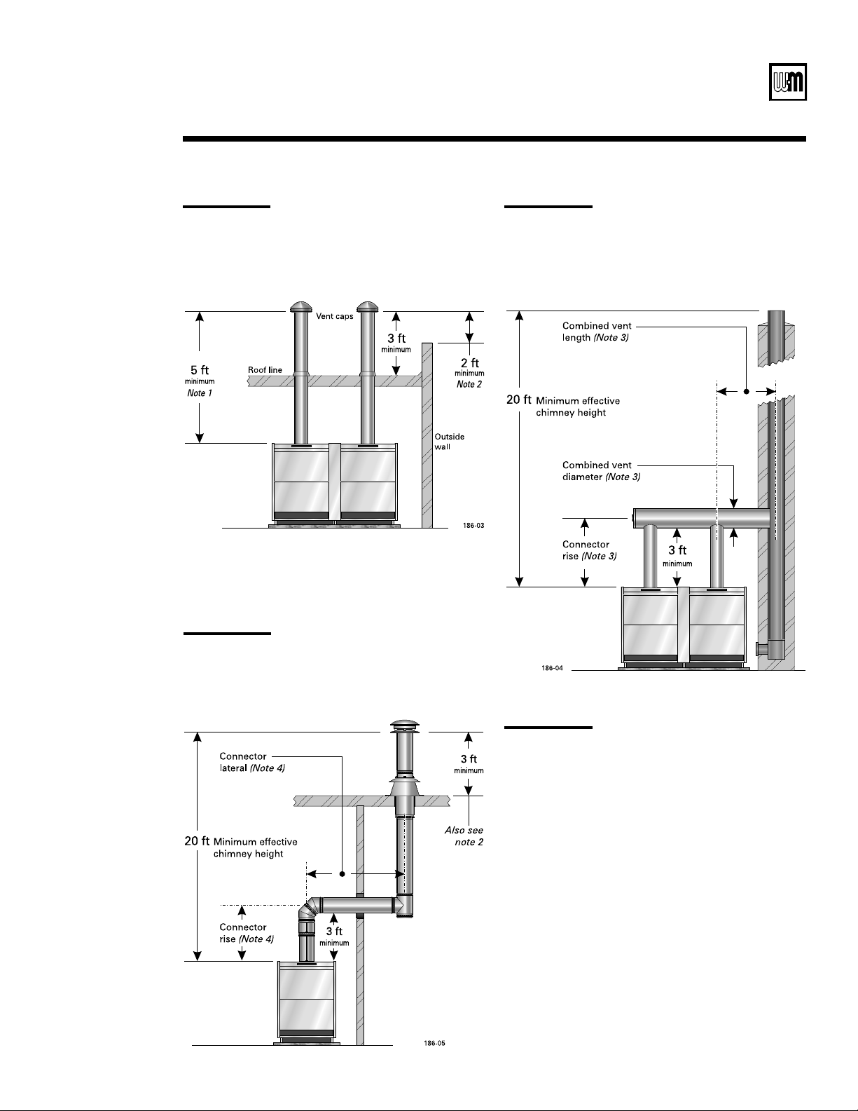
Pre-installation — venting
See Figures 3, 4 and 5ONPAGEFORTYPICALVENTINGCONlGURATIONS%NSURETHATYOURINSTALLATION
COMPLIESWITHTHEREQUIREMENTSGIVENINTHESEILLUSTRATIONSANDWITHALLLOCALCODESANDSTANDARDS
See the
Ratings table on page 36, for minimum breeching diameter. Use heavy gauge steel
breeching (Type B vent material or single wall metal pipe). Where horizontal breeching is
used, slope upward at least ¼” per foot toward chimney or vent and support with hangers to
prevent sagging.
Long horizontal breechings, excessive numbers of elbows or tees, or other
obstructions restricting flow of combustion gases can result in possibility
of flue gas spillage and carbon monoxide emissions, causing severe personal
injury or death.
Failure to follow all instructions listed below can cause flue spillage and
carbon monoxide emissions, resulting in severe personal injury, death or
substantial property damage.
-
Individual
stub vents
/
Combined
vents
0
Offset
vents
Part Number 550-141-186/0914
7
s)NSTALLATIONs3TART5Ps-AINTENANCEs0ARTS
Notes
-INIMUMVENTHEIGHTUSINGFULLSIZECONNECTOR
2. -INIMUM FEETABOVEANYSTRUCTUREWITHIN
FEET
3. Vent and combined vent materials, length
and diameter must be determined using the
COMBINEDVENTINGTABLESOFTHE.ATIONAL&UEL
'AS#ODE!.3):nLATESTEDITIONOROTHER
accepted engineering design method. Use a
connector rise as high as possible to improve
vent connector capacity.
4. Vent and vent connector material and design
must be determined using the individual
VENTINGTABLESOFTHE.ATIONAL&UEL'AS#ODE
!.3):nLATESTEDITIONOROTHERACCEPTED
engineering design method. Use a connector
rise as high as possible to improve vent con-
nector capacity.
1
Foundation
Part Number 550-141-186/0914
8
LGB
3ERIES'AS&IRED"OILER"OILER-ANUAL
1c
Pre-installation — foundation
Suggested minimum clearances for servicing:
s INCHESFORACCESSTOCONTROLSANDCOMPONENTSFRONTANDSIDES
s INCHESFROMDRAFTHOODTOWALLFORCLEANINGmUEWAYS
2EQUIREDCLEARANCESINCONlNEDSPACES
s 6ENTPIPEMUSTBEATLEASTINCHESFROMCOMBUSTIBLEMATERIAL
s -INIMUMvBETWEENJACKETANDCOMBUSTIBLEWALLSANDCEILING
&OR,'"THROUGH,'" )2) AND ,'"THROUGH ,'"&-#3$ THE GAS TRAINIS
located outside the boiler. Provide additional clearance.
Install in a space large in comparison to size of boiler.
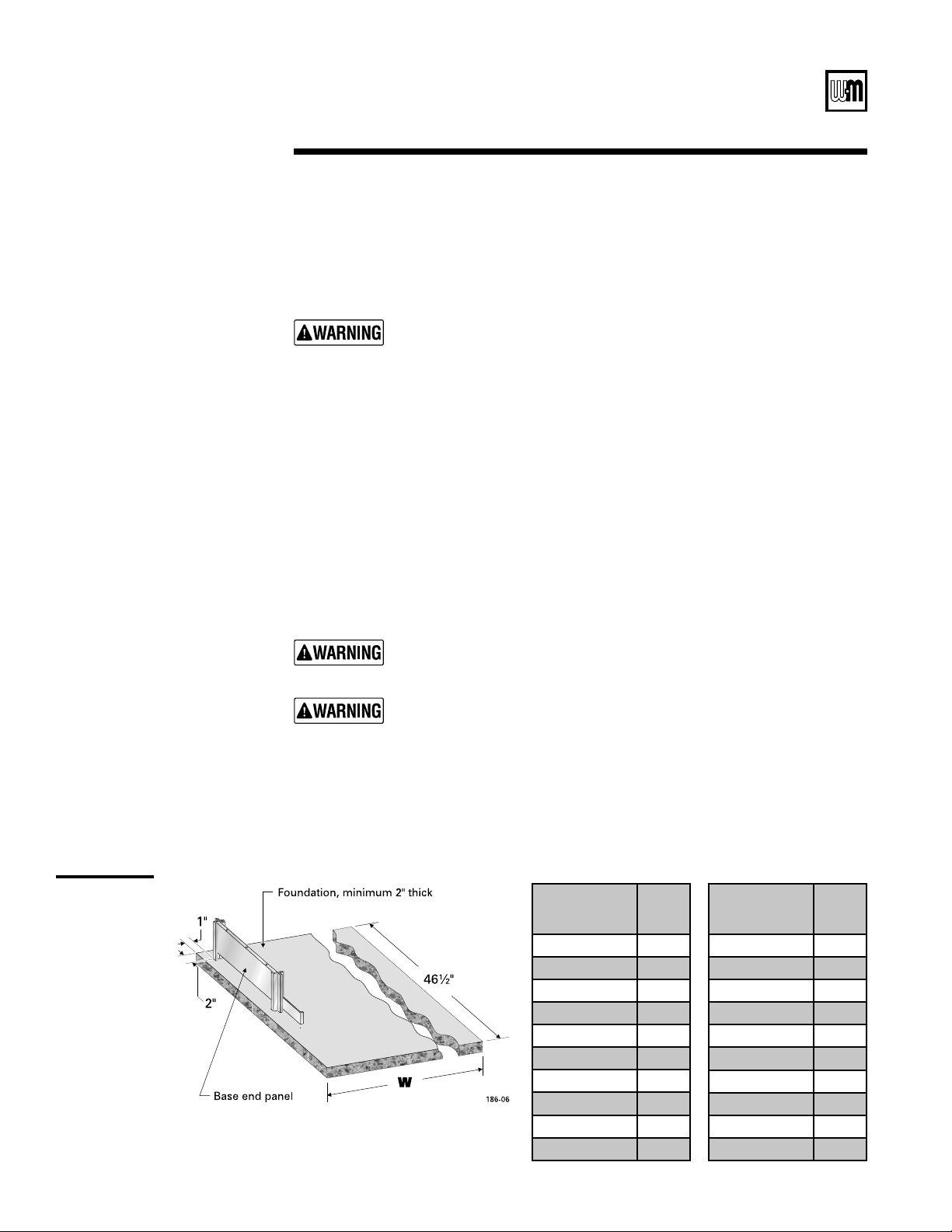
Level concrete or brick foundation, minimum 2” thick, (Figure 6ISREQUIREDIF
s 4HEREISAPOSSIBILITYOFTHEmOORBECOMINGmOODED
s .ONLEVELCONDITIONSEXIST
Use foundation with airways when concrete floor is “green”.
&IREHAZARD.EVERINSTALLBOILERONCOMBUSTIBLEmOORINGORCARPETINGEVEN
if a concrete or aerated foundation is used. Severe personal injury, death or
substantial property damage can result.
Do not route wiring, telephone cables or piping in the floor below the
boiler. Overheating could occur, resulting in severe personal injury, death
or substantial property damage.
2
Consider all connections to the boiler before selecting a location.
Boiler must be installed so gas control system components are protected from dripping or
spraying water or rain during operation or service.
Flammable materials
To avoid personal injury, death or property damage, keep the boiler area
clear and free from combustible materials, gasoline and other flammable
VAPORSANDLIQUIDS
Boiler
Model
Number
“W”
Inches
LGB-4 21
LGB-5 26
LGB-6 31
LGB-7 36
LGB-8 41
LGB-9 46
LGB-10 51
LGB-11 56
LGB-12 61
LGB-13 66
Boiler
Model
Number
“W”
Inches
LGB-14 71
LGB-15 76
LGB-16 81
LGB-17 86
LGB-18 91
LGB-19 96
LGB-20 101
LGB-21 108
LGB-22 111
LGB-23 116
3
Base
assembly
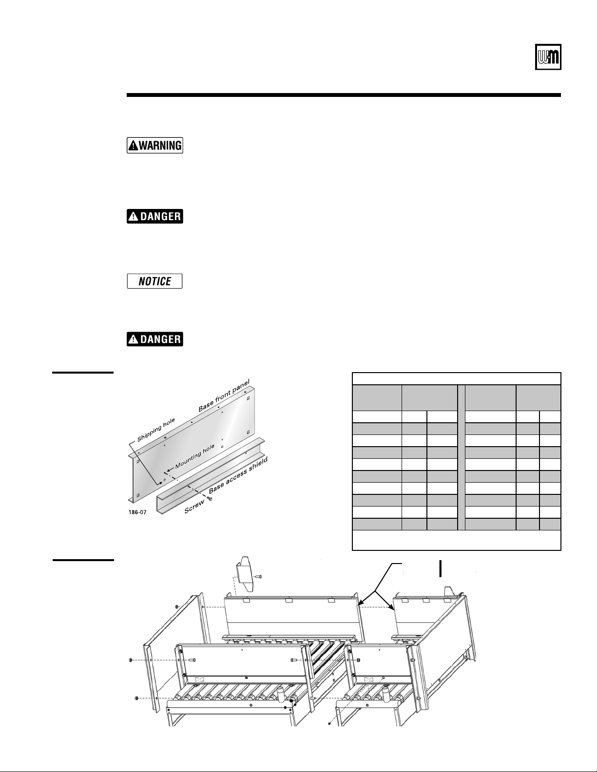
4
Access shield
(sizes D,
E, F and G
shown)
Part Number 550-141-186/0914
s)NSTALLATIONs3TART5Ps-AINTENANCEs0ARTS
Check for proper orifice size:
s .ATURALGASnMM
s 0ROPANEGASnMM
Assembly order
Burner seating
Before assembling base, relocate access shield from lower shipping holes to upper mounting holes. See Figure 7.
s "ASESIZES!"AND#ONEMOUNTINGHOLE
s "ASESIZES$%&AND'TWOMOUNTINGHOLES
Proper orifices must be used. Failure to do so will cause severe personal injury, death or sub-
stantial property damage.
Assemble base(s) as shown in
Figure 8, in the order shown in the table below. Dual base shown.
Level and straighten burners to avoid misfiring.
Base assembly must be located in order shown in Base Arrangement Table, below, so flue
collector/draft hoods, jackets, and gas controls are installed in correct position.
Burners must be properly seated in their locating slots with openings facing up. Front of
burners must rest fully over main burner orifices. Gas orifices must inject down center of
burners. Failure to properly level and seat burners will result in severe personal injury, death
or substantial property damage.
2a
Boiler assembly — base
The boiler contains ceramic fiber and fiberglass materials. Use care when handling these materials
per instructions on page 28 of this manual. Failure to comply could result in severe personal injury.
Base Arrangement Table (Note 1)
Boiler
Model
Number
Base Size
Boiler
Model
Number
Base Size
LGB-4 4 --- LGB-14 CB
LGB-5 5 --- LGB-15 CC
LGB-6 A --- LGB-16 DC
LGB-7 B --- LGB-17 DD
LGB-8 C --- LGB-18 ED
LGB-9 D --- LGB-19 EE
LGB-10 E --- LGB-20 FE
LGB-11 F --- LGB-21 FF
LGB-12 G --- LGB-22 GF
LGB-13 BB LGB-23 GG
Note 1: From boiler left side (front view). Side panels
shipped in separate carton.
For dual
base only
where two base connect.
For dual
b
ase on
l
y
w
h
ere t
w
5
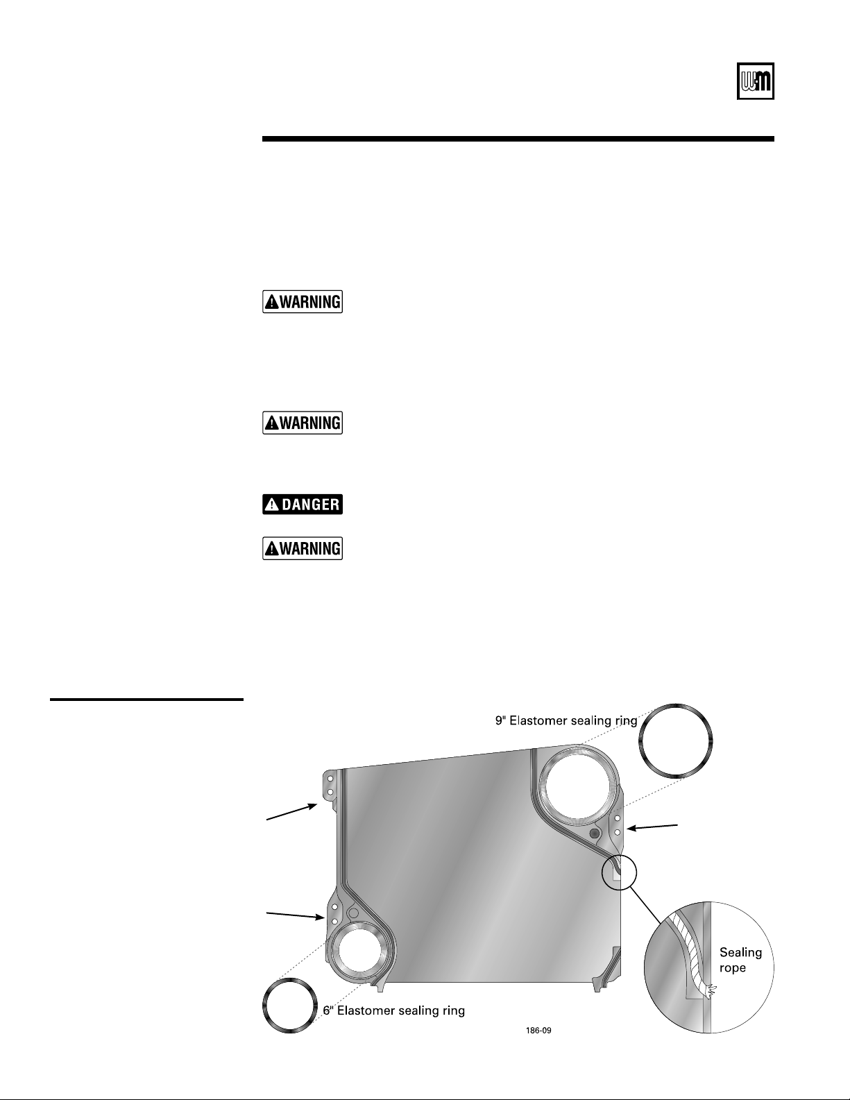
Sealing rope, seals, and draw
rod tightening sequence
2b
Boiler assembly — sections
Part Number 550-141-186/0914
LGB
3ERIES'AS&IRED"OILER"OILER-ANUAL
Assembly may start at either end section.
For easier assembly start with right end section.
0OSITIONRIGHTENDSECTIONmUSHWITHRIGHTENDOFBASE3EE
Figure 13ONPAGE
2
2. With caulking gun, apply
/
8
” continuous bead of sealing rope adhesive in sealing grooves.
See Figure 9.
0LACEvROPEINGROOVE!ROUNDCURVESGRASPATvINTERVALSANDPUSHTOGETHER$O
not stretch. Cut rope as each section is completed. See Figure 9.
2EMOVEANYGRITFROMPORTOPENINGSEALINGSURFACESWITHCLEANRAG.OTEWarning below.
5. Place sealing rings in port openings. See
Figure 9.
Clean port
sealing surfaces
Remove all grit or rust from port opening sealing surfaces. Failure to do
so may cause a seal failure, resulting in severe personal injury, death or
substantial property damage.
No petroleum-
based chemicals
$ONOTUSEANYCLEANERCONTAININGPETROLEUMBASEDDISTILLATEOIL%LASTOMER
seal failure will occur, causing substantial property damage.
Do not precut
rope
Do not precut rope. Gas tight seal must be maintained to prevent possibil-
ity of flue gas spillage and carbon monoxide emissions, causing personal
injury or death.
Sections are
top-heavy
Sections are top heavy and will not stand individually without support.
Severe personal injury, death or substantial property damage can result.
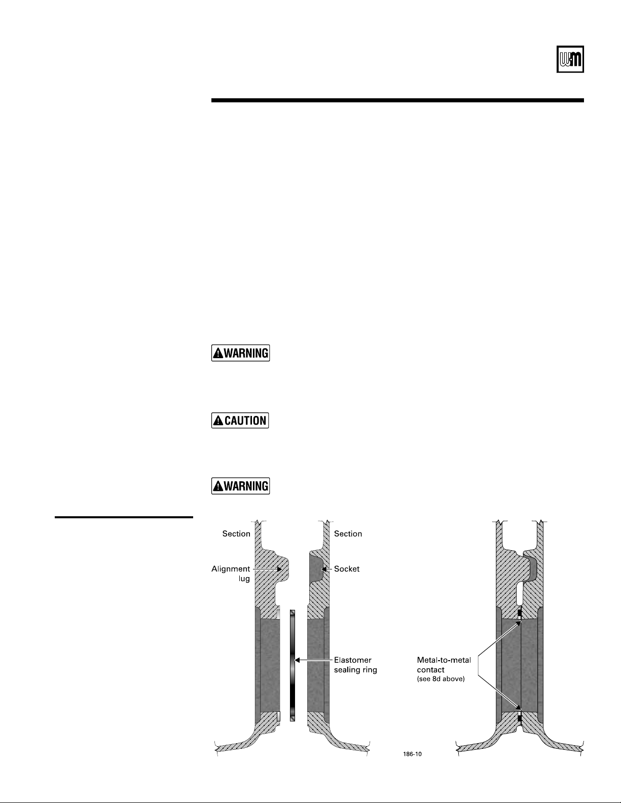
6. Prepare intermediate section:
A 2EMOVEGRITORRUSTFROMPORTOPENINGSEALINGSURFACES.OTE
Warning above.
b. Position intermediate sections so alignment lugs fit into sockets of next section.
Refer to
Figure 10PAGE
7. Discard
3
/
8
” diameter shipping tie rods. Do not use to draw sections together.
First draw rod
Second draw rod
Third draw rod
Part Number 550-141-186/0914
s)NSTALLATIONs3TART5Ps-AINTENANCEs0ARTS
2
(continued)
*6
Sealing ring installation and
port alignment
8. Place all sections on base assembly insuring sections are straight and properly aligned
with alignment lugs. Snug the lower front and rear draw rods on every section. Do
not tighten front upper draw rods. Front upper draw rods must remain loose until
LOWERFRONTANDREARDRAWRODSARETIGHTENEDTOPROPERTORQUE3EE
Figure 10.
a. Oil threads on all draw rods. Install washer and nut on end to be tightened. Use
nut only on other end.
b. Uniformly draw sections together, starting at washer/nut end. Tighten lower front
and rear draw rods uniformly and progress through every section to the end.
.OTE!SSTATEDEARLIERUPPERFRONTDRAWRODNUTSSHOULDREMAINLOOSEUNTILLOWER
FRONTANDREARDRAWRODSARETIGHTENEDTOPROPERTORQUE
C $RAWRODSSHOULDBETORQUEDTOARANGEOFFTLBSINSEQUENCESHOWNIN
&IGURE(OWEVERDONOTTIGHTENTHETHIRDUPPERFRONTDRAWRODUNTILALLLOWER
FRONTANDREARDRAWRODSARETIGHTENEDSEQUENTIALLYTOPROPERTORQUE$ONOTBACK
off draw rods once they are tightened.
D -ETALTOMETALCONTACTWILLBEACHIEVEDAROUNDPORTOPENING3EE
Figure 10. If a
GAPDOESEXISTITSHOULDBENOGREATERTHANv#HECKWITHFEELERGAUGE
e. Tighten third, upper front draw rod just enough to get good even compression on
the rope.
&OLLOWSTEPSTHROUGHFORREMAININGINTERMEDIATESANDLEFTENDSECTION
Check sealing
rope
Check sealing rope of each section before proceeding to next section. Boiler
must be sealed gas-tight to prevent possibility of flue gas spillage and carbon
monoxide emissions, causing severe personal injury or death.
End section
must be plumb
%NDSECTIONMUSTBEPLUMB!FTERERECTINGSTINTERMEDIATESECTIONCHECK
both sections for plumb. Failure to plumb sections may cause misaligned
piping and breeching, resulting in minor property damage.
Verify metal to
metal contact
at ports
)FFORANYREASONGAPAROUNDPORTOPENINGEXCEEDSvCHECKFORROPE
extending from rope grooves, dirt on port openings or sockets, or misaligned
LUGS)FCORRECTIONSAREMADEANDGAPSTILLEXISTSCONTACTYOUR7EIL-C,AIN
distributor or sales office before continuing installation. Failure to correct
this situation could cause seal failure, resulting in severe personal injury,
death or substantial property damage.
Part Number 550-141-186/0914
LGB
3ERIES'AS&IRED"OILER"OILER-ANUAL
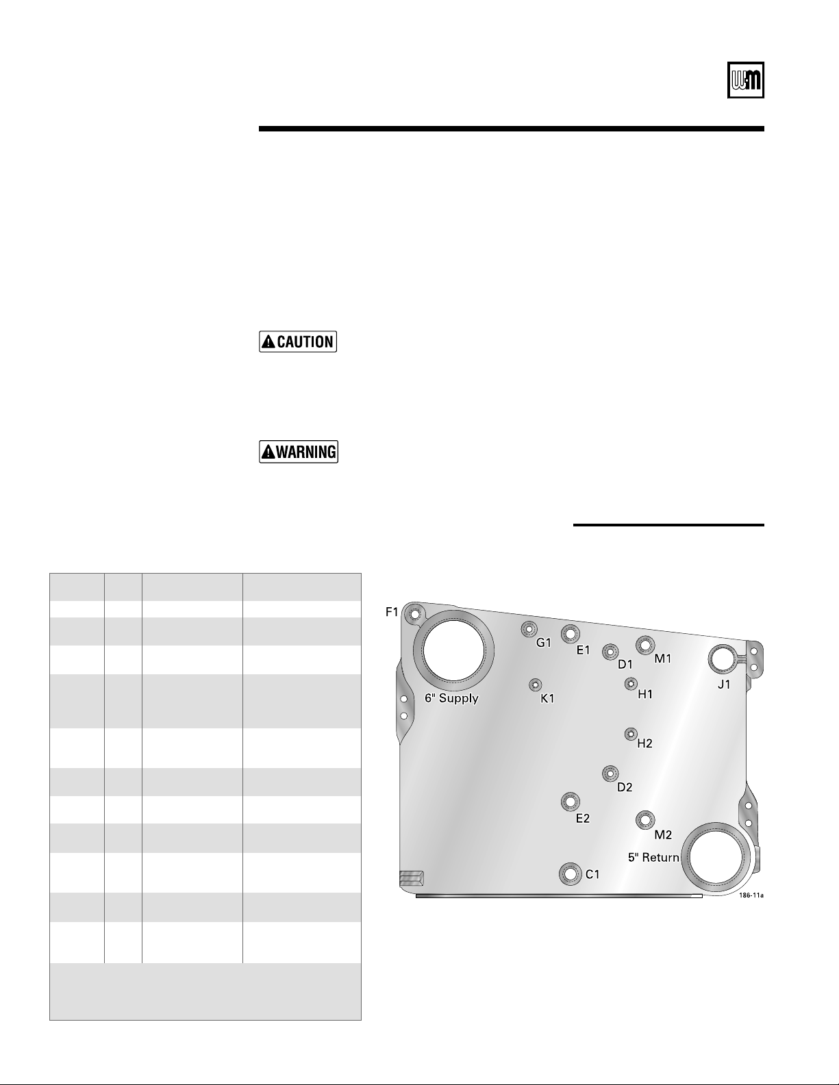
7
Pressure test before connecting gas piping and electrical supply.
Refer to Figures 11a and 11b for control tapping locations. Install:
a. Boiler drain (not supplied).
b. Water pressure gauge — for test only. Be sure gauge can handle test pressures. See
Step 3.
2. Plug remaining tappings.
**
Left end section tappings
2c
Boiler assembly — pressure test
&ILLBOILER6ENTALLAIR&ORMORETHANMINUTESPRESSURETEST
a. Steam boilers between 45 - 55 psig.
B 7ATERBOILERSTIMESMAXIMUMWORKINGPRESSURESTATEDONCASTINGSANDBOILER
nameplate.
No controls
installed
DO NOT pressure test with any controls installed. Damage to control can
occur.
Do not
leave boiler
unattended
Do not leave boiler unattended. Cold water fill could expand and cause
excess pressure, resulting in severe personal injury, death or substantial
property damage.
Tapping Size
Inches
Steam Boilers Water Boilers
(note 4)
C1 1
1
/
4
Boiler drain Boiler drain
D1 & D2
1
/
2
Gauge glass
(note 3)
--
E1 & E2 1 Low water cutoff
(note 3)
Optional low water
cutoff
E1 1 Pressure
operating & limit
controls and
pressure gauge
Limit control
(note 2)
F1 1 -- To expansion tank or
automatic air vent
(note 2)
G1
3
/
4
-- Operating control
(note 2)
H1 & H2
(note 1)
3
/
8
Tri-cock --
J1 2 Steam relief valve
& skim tapping
Water relief valve &
skim tapping
K1
1
/
2
-- Combination pressure
& temperature gauge
(note 2)
M1 & M2 1 Optional low water
cutoff
(note 3)
Optional low water
cutoff
M1 1 Firing rate control
(when used)
Firing rate control
(when used) or Probe
low water cutoff
Notes:
1. Available on special request only.
2. Must be on same side as supply to system.
3. Must be on same side as steam equalizer piping.
4. Additional controls for water boilers may be placed in supply piping.
Part Number 550-141-186/0914
s)NSTALLATIONs3TART5Ps-AINTENANCEs0ARTS
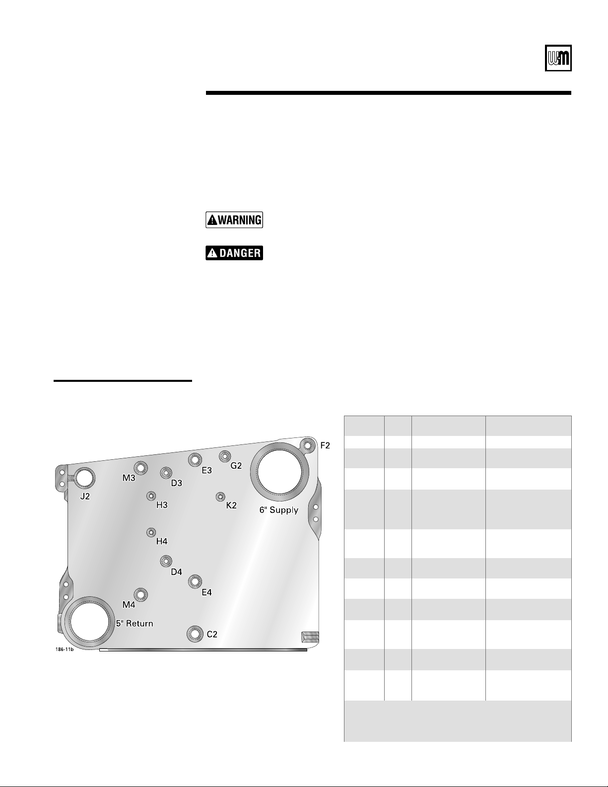
**
Right end section tappings
7
(continued)
No petroleum-
based chemicals
4. Check for maintained gauge pressure and leaks. Repair if found.
5. Drain boiler and remove plugs from tappings used for controls and accessories.
Do not use petroleum-based cleaning or sealing compounds in boiler system.
Severe damage to boiler will result, causing substantial property damage.
Repair leaks
at once
Leaks must be repaired at once. Failure to do so can damage boiler, resulting
in substantial property damage.
Tapping Size
Inches
Steam Boilers Water Boilers
(note 4)
C2 1
1
/
4
Boiler drain Boiler drain
D3 & D4
1
/
2
Gauge glass
(note 3)
--
E3 & E4 1 Low water cutoff
(note 3)
Optional low water
cutoff
E3 1 Pressure
operating & limit
controls and
pressure gauge
Limit control
(note 2)
F2 1 -- To expansion tank or
automatic air vent
(note 2)
G2
3
/
4
-- Operating control
(note 2)
H3 & H4
(note 1)
3
/
8
Tri-cock --
J2 2 Steam relief valve
& skim tapping
Water relief valve &
skim tapping
K2
1
/
2
-- Combination pressure
& temperature gauge
(note 2)
M3 & M4 1 Optional low water
cutoff
(note 3)
Optional low water
cutoff
M3 1 Firing rate control
(when used)
Firing rate control
(when used) or Probe
low water cutoff
Notes:
1. Available on special request only.
2. Must be on same side as supply to system.
3. Must be on same side as steam equalizer piping.
4. Additional controls for water boilers may be placed in supply piping.
Part Number 550-141-186/0914
LGB
3ERIES'AS&IRED"OILER"OILER-ANUAL
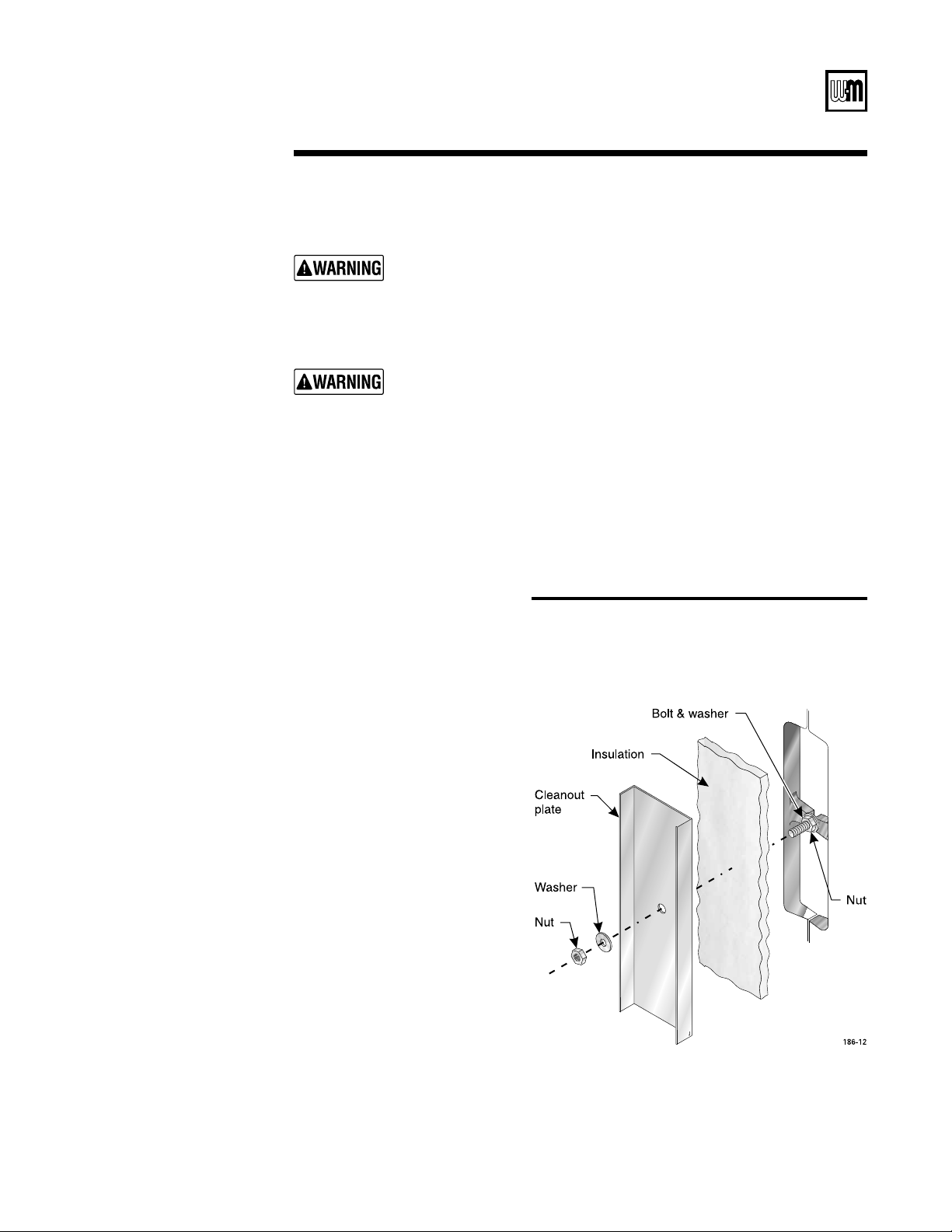
!
Assemble cleanout plates to section assembly as shown in Figure 12.
Gas-tight seal
Cleanout plates must be sealed gas-tight to prevent possibility of flue gas
spillage and carbon monoxide emissions, causing severe personal injury or
death.
The boiler contains ceramic fiber and fiberglass materials. Use care when
handling these materials per instructions on
page 28 of this manual. Failure
to comply could result in severe personal injury.
*+
Cleanout plate assembly
2d
Boiler assembly — cleanout plates
Boiler Model
Number
Flue Collector Hood(s)
(from left side of boiler)
LGB-4 4 ---
LGB-5 5 ---
LGB-6 A ---
LGB-7 B ---
LGB-8 C ---
LGB-9 D ---
LGB-10 E ---
LGB-11 F ---
LGB-12 G ---
LGB-13 BB
LGB-14 CB
LGB-15 CC
LGB-16 DC
LGB-17 DD
LGB-18 ED
LGB-19 EE
LGB-20 FE
LGB-21 FF
LGB-22 GF
LGB-23 GG
Part Number 550-141-186/0914
s)NSTALLATIONs3TART5Ps-AINTENANCEs0ARTS
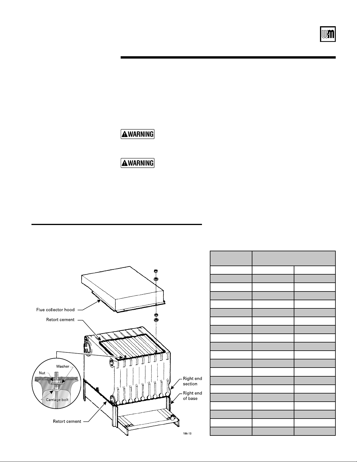
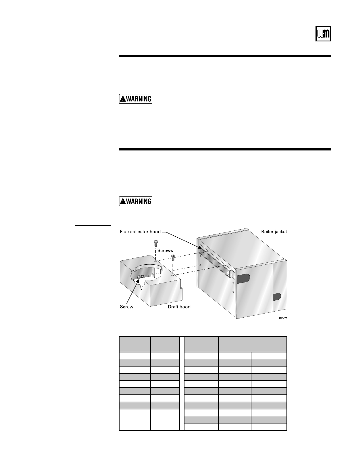
See Figure 13 — single base shown.
Refer to the
table below, for proper arrangement.
!SSEMBLEBOLTWASHERANDNUTTOSECTIONJOINT
2. Apply retort cement for gas-tight seal.
*-
Flue collector hood assembly and sealing the boiler
Gas-tight seal
2e
Hood must be sealed gas-tight to prevent possibility of flue gas spillage and
carbon monoxide emissions, causing severe personal injury or death.
-OUNTHOODONSECTIONASSEMBLY&ASTENWITHWASHERSANDNUTS
Apply retort cement between bottom of sections and top of base assembly. See
Figure 13.
Sealing the
boiler
Boiler must be sealed gas-tight to prevent possibility of flue gas spillage and
carbon monoxide emissions, causing severe personal injury or death.
Part Number 550-141-186/0914
LGB
3ERIES'AS&IRED"OILER"OILER-ANUAL
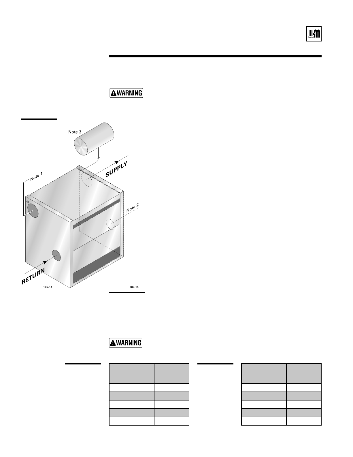
)NSTALLSYSTEMSUPPLYANDRETURNPIPINGBEFOREERECTINGJACKETORINSTALL-
ing controls.
2. Do not pipe in through supply and out through return. This creates
reverse water flow that must not be used.
%XPANSIONTANK
A #LOSEDTYPEEXPANSIONTANKCONNECTTOvTAPPINGh
F” (refer to Ta p -
ping tables
PAGESAND5SEv.04PIPING!NYHORIZONTAL
PIPINGMUSTPITCHUPWARDTOWARDTANKATLEASTINCHFOREACHFEET
of piping. See
Figure 14.
b. Diaphragm type expansion tank — locate between supply and inlet
to circulator. Install automatic air vent in tapping “F”.
4. Connect supply and return piping:
a. Size according to tables on this page.
b. Install circulator in supply piping, with the expansion tank
located on the suction side of the circulator.
C )NSTALLSYSTEMDRAINVALVESIZEDPER!3-%#ODE
Models LGB-4 – LGB-12 — use 1” drain valve.
Models LGB-13 – LGB-23 — use 1¼” drain valve.
5. When three-way valves are used for temperature modulation, install
slow-opening valves and boiler mixing pump to minimize potential of
boiler thermal shock. See
Weil-McLain Bulletin AE-8402.
-ULTIPLEBOILERSSEEFigure 15PAGE
0IPINGSHOULDBESIZEDFORA&RISETHROUGHTHEBOILER3EETable 1,
below. For higher flow rates (when specified), use pipe sizes no smaller
than those given in Table 2, below.
8*
20°F rise
through
boiler
#
9
3a
Piping — water boilers
Improper piping systems and/or undersized piping can contribute to erratic
boiler operation and possible boiler damage. Install piping as shown below.
LGB-4 through LGB-12 only — supply and return piping can be on same
end.
Intermittent flow at higher velocities than shown for pipe size in Table 2,
below, can damage boiler causing substantial property damage.
1 -ODELS,'"THROUGH,'"ONLYALTERNATESUPPLYTAPPINGFORSUPPLYANDRETURN
on same end.
2 -ODELS,'"THROUGH,'"ONLYALTERNATERETURNTAPPINGFORSUPPLYANDRETURN
on same end.
3 Location for closed type expansion tanks only. Locate diaphragm type expansion tanks
between boiler supply connection and circulator suction connection.
:
8+
Boiler
Model
Number
Pipe Size
Supply &
Return
LGB-4
2”
LGB-5
2½”
LGB-6 – LGB-8
3”
LGB-9 – LGB-16
4”
LGB-17 – LGB-23
5”
Water Flow Rate
GPM
Pipe Size
Supply &
Return
Up to 35
2”
36 to 50
2½”
51 to 77
3”
78 to 142
4”
143 to 237
5”
*/
Water boiler
piping
1
2
3
4
5
6
Part Number 550-141-186/0914
s)NSTALLATIONs3TART5Ps-AINTENANCEs0ARTS
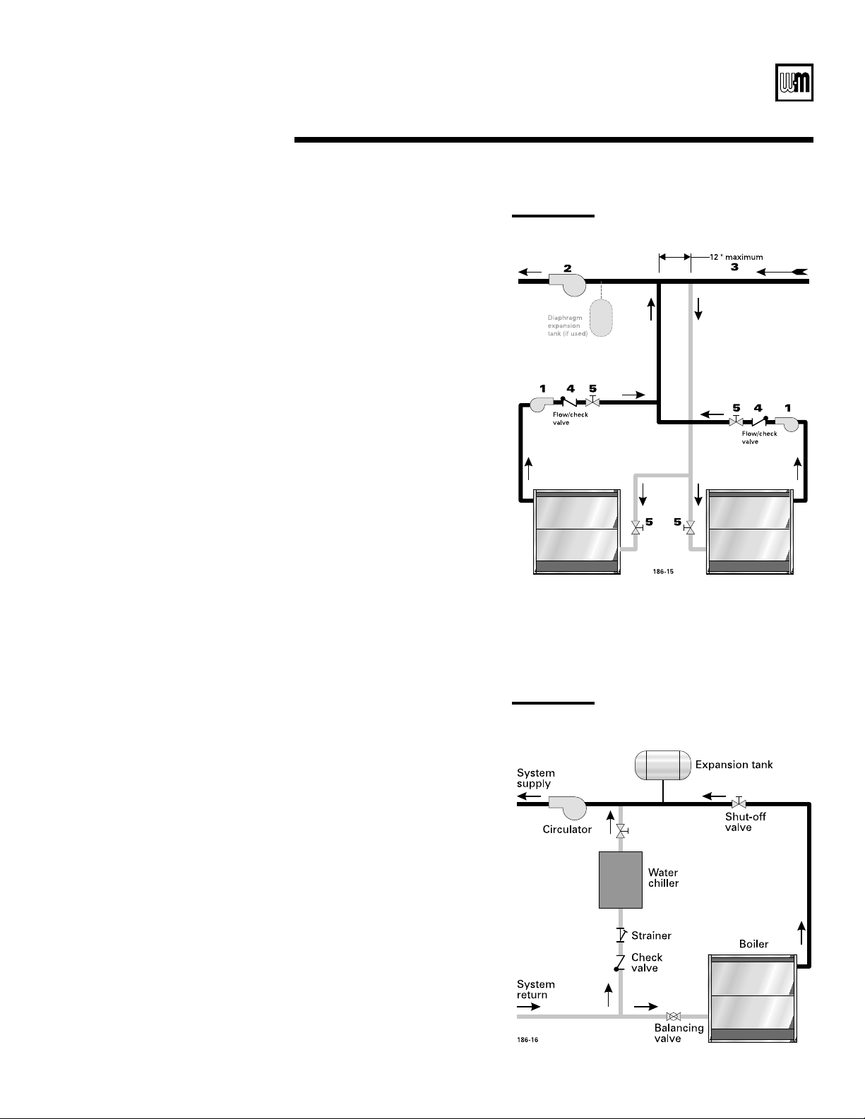
;
(systems above 140°F)
7EIL-C,AINRECOMMENDSPIPING
as shown in
Figure 15. For single
boilers, pipe as shown for one unit.
3IZESECONDARYBOILERPUMP'0-
FOR&TO&TEMPERATURE RISE
through boiler. Secondary boiler
pump head will be very low. Cal-
culate only secondary piping circuit
resistance. Boiler resistance will not
exceed 6” w.c.
0RIMARY PUMP '0- AND HEAD
calculation should not include
secondary boiler circuits. Primary
pump can operate continuously
during heating season.
$ISTANCEvORLESS
Flow/check valve.
Hand valve.
%XPANSIONTANKSRELIEFVALVESAND
OTHERACCESSORIESAREREQUIREDBUT
not shown.
#
The boiler must be installed so that
chilled medium is piped in parallel
with the heating boiler with appro-
priate valves to prevent the chilled
medium from entering the boiler.
See
Figure 16. Consult AHRI In-
stallation and Piping Guides.
If boiler is connected to heating
coils located in air handling units
where they can be exposed to
refrigerated air, gravity circula-
tion during cooling cycle must be
prevented with flow control valves
or other automatic means.
*0
*1
Part Number 550-141-186/0914
LGB
3ERIES'AS&IRED"OILER"OILER-ANUAL
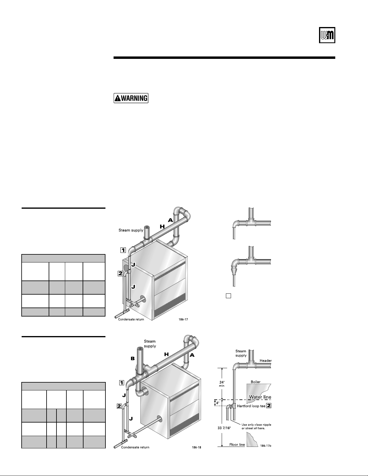
Pipe the header at least 24 inches above the boiler water line.
7EIL-C,AINRECOMMENDSUSINGABOILERFEEDSYSTEMWITHTHEPUMPOPERATEDBYALEVELCON-
TROLLERONTHEBOILER7EIL-C,AINDOESNOTRECOMMENDUSINGACONDENSATERETURNSYSTEMON
which the pump is operated by a receiver-mounted float switch. Level controls (Section 6)
MUSTBEMOUNTEDONSAMESIDEOFBOILERASTHERETURNPIPINGANDEQUALIZER
Install a blowdown valve in tapping
C1 or C2 (see Figures 11a and 11bPAGESAND
SIZEDPER!3-%#ODE
Models LGB-4 through LGB-12USEvBLOWDOWNVALVE
Models LGB-13 through LGB-23USEvBLOWDOWNVALVE
See Figure 200AGEFORMULTIPLESTEAMBOILERPIPING
*4
Steam boiler piping for
LGB-4 through LGB-12
(single riser)
*3
Steam boiler piping for
LGB-13 through LGB-23
(riser each end)
3b
Piping — steam boilers
Improper piping systems and/or undersized piping can contribute to erratic
boiler operation and possible boiler damage. The piping must be installed
as illustrated, using the recommended minimum pipe sizes.
Minimum Recommended Pipe Sizes
Boiler
Model
Number
Riser
A
Header
H
Equalizer
J
LGB-4 ––
LGB-8
4” 4” 2”
LGB-9 ––
LGB-11
5” 5” 2½”
LGB-12
6” 6” 2½”
Minimum Recommended Pipe Sizes
Boiler
Model
Number
Risers
A B
Header
H
Equalizer
J
LGB-13 ––
LGB-15
4” 4” 6” 4”
LGB-16 ––
LGB-19
5” 5” 6” 4”
LGB-20 ––
LGB-23
6” 6” 8” 4”
OR
Reducing from header
to equalizer - alternate
piping methods.
DO NOT reduce the
header in the
horizontal piping.
1
186-17a
2"
Isolation valve
Strainer
Feed pump
Check valve
Receiver
Return
Vent to atmosphere
Boiler
Hartford loop
186-19
Part Number 550-141-186/0914
s)NSTALLATIONs3TART5Ps-AINTENANCEs0ARTS
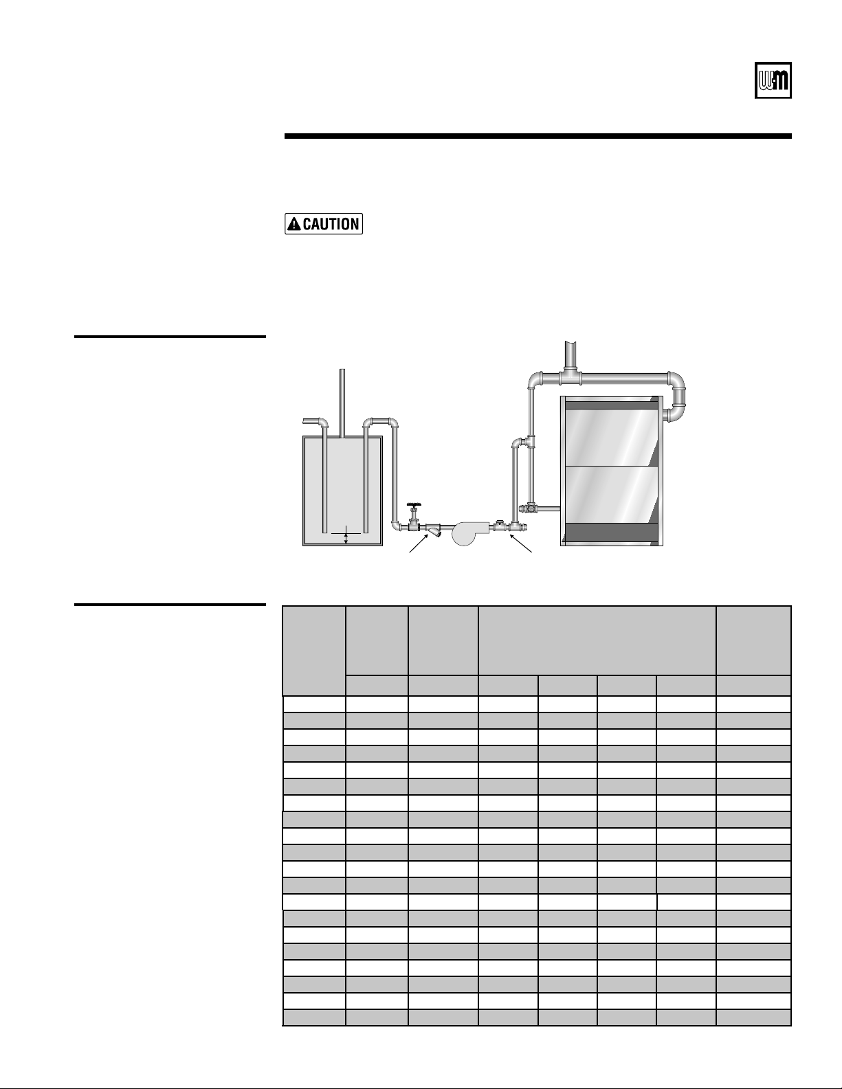
!)
3ATISFACTORYOPERATIONOFANYSTEAMHEATINGSYSTEMDEPENDSUPONADEQUATE
return of condensate to maintain steady water level. Avoid adding excessive
AMOUNTOFRAWMAKEUPWATER7HERECONDENSATERETURNISNOTADEQUATEA
low water cutoff and pump control, condensate receiver, and condensate
boiler feed pump should be installed. Refer to
Figure 19 for piping and
condensate receiver capacity table for sizing.
*5
Boiler feed pump and
condensate receiver piping
8-
Condensate receiver capacity
(minimum)
Boiler
Model
Number
Gross
Output
Steam
Condensate Minimum Condensate Receiver Capacity
Select minimum receiver capacity based on time
(minutes), required for condensate to return to the
receiver.
Recommended
Feed Pump
Capacity
lbs/hour 15 min 30 min 45 min 60 min
GPM @15 PSI
LGB-4 312.0 39 12 23 35 47 1.3
LGB-5 409.2 51 15 30 46 61 1.7
LGB-6 514.2 63 19 38 58 77 2.1
LGB-7 619.3 76 23 46 68 91 2.5
LGB-8 724.4 88 26 52 78 104 2.9
LGB-9 828.9 101 30 60 90 120 3.3
LGB-10 933.7 114 34 68 102 136 3.8
LGB-11 1038.7 126 38 76 114 152 4.2
LGB-12 1144.0 139 42 84 126 168 4.6
LGB-13 1238.6 152 46 92 138 184 5.1
LGB-14 1343.6 164 49 98 147 196 5.5
LGB-15 1448.7 177 53 106 159 212 5.9
LGB-16 1552.2 190 58 116 174 232 6.3
LGB-17 1657.8 202 61 122 183 244 6.7
LGB-18 1763.6 215 65 130 195 260 7.1
LGB-19 1867.3 227 68 136 204 272 7.5
LGB-20 1973.6 240 72 144 216 288 8.0
LGB-21 2077.4 253 76 152 228 304 8.4
LGB-22 2184.0 265 79 158 237 316 8.8
LGB-23 2288.0 278 83 166 249 332 9.2
Part Number 550-141-186/0914
LGB
3ERIES'AS&IRED"OILER"OILER-ANUAL
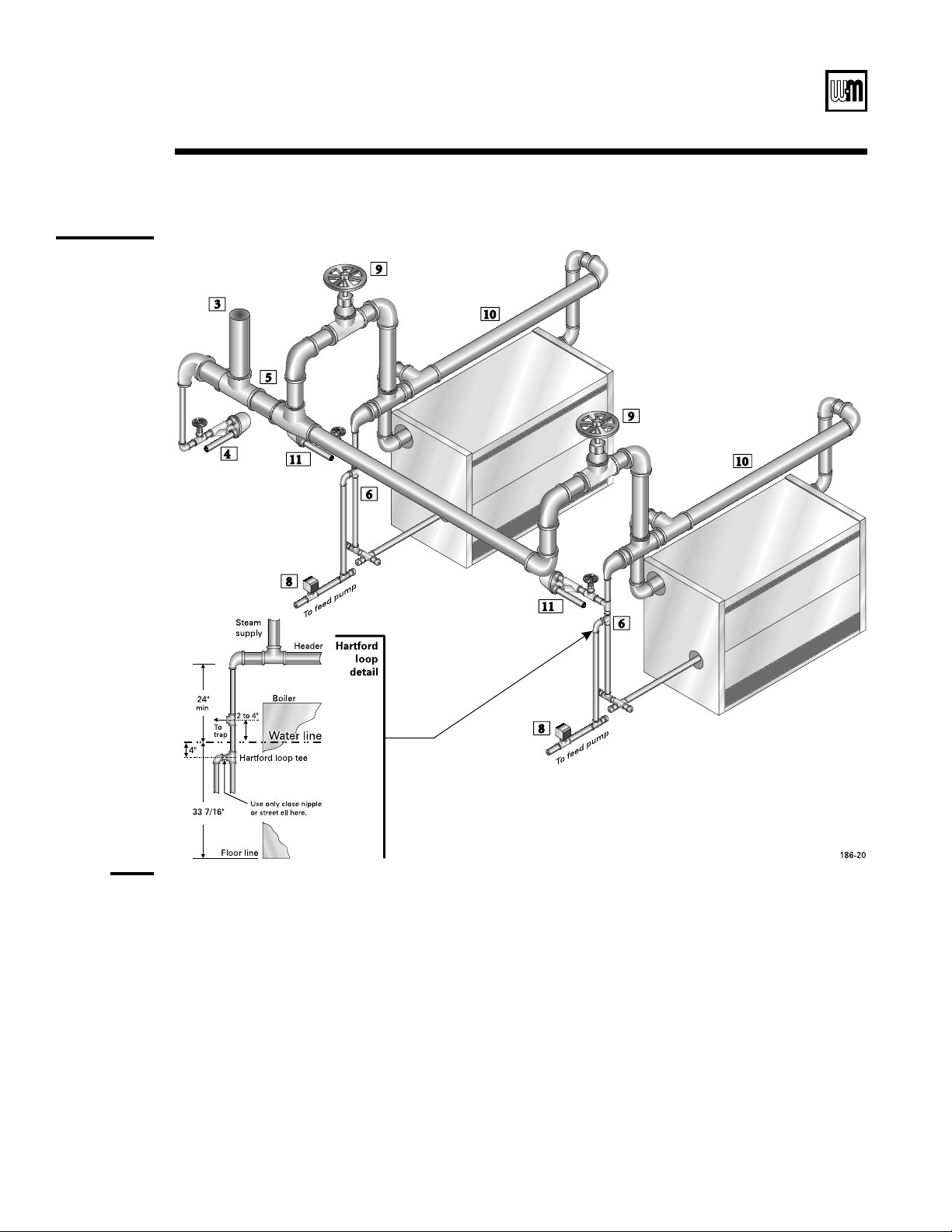
+6
Piping
multiple
steam boilers
3c
Piping — multiple steam boilers
:
1 %ACHBOILERHASABOILERFEEDPUMPCONTROLLERNOTSHOWN,EVELCONTROLS3ECTIONMUSTBEMOUNTEDONSAMESIDEOFBOILERASRETURN
2 -OUNTEACHBOILERFEEDPUMPCONTROLLERWITHBODYMARKATTHELEVELINDICATEDIN4ABLEPAGEAND&IGUREPAGE
3 ,OCATESYSTEMSTEAMSUPPLYTAKEOFFOUTBOARDFROMTHEBOILERCONNECTINGPIPINGASSHOWNTOASSURELIQUIDINLINEWILLmOWTOTRAP
4 Locate combined header drain as shown. Install strainer and float and thermostatic trap in drain line as shown. Pipe trap outlet to condensate
receiver.
5 3IZETHECOMMONHEADERPIPINGPER!3(2!%RECOMMENDATIONSANDINNOCASESMALLERTHANTHEINDIVIDUALBOILERHEADERS
6 Pipe the Hartford Loop tee 4” below boiler waterline.
7 Boiler controls and trim (valves, low water cutoffs, pump controllers, burners, etc.) are omitted in order to emphasize steam and return piping.
8 Provide a separate feed pump for each boiler. Alternatively, provide a separate automatic valve with end switch and a single feed pump. When
valves are used, activate the valve with the boiler pump controller. Activate the feed pump with the valve end switch.
9 -ANUALSTEAMVALVEORSLOWOPENINGAUTOMATICSTEAMVALVESIZEDTOBOILEROUTPUTCAPACITY
10 "OILERSTEAMHEADERFORSINGLEBOILERSEEPAGE
11 )NSTALLAmOATANDTHERMOSTATICTRAPANDSTRAINEROFFTHEEQUALIZEROFEACHBOILERFROMTOINCHESABOVETHEWATERLINE#ONNECTTHETRAP
outlet to the condensate receiver. The trap will prevent an idle boiler from flooding due to condensed steam from the system.
Part Number 550-141-186/0914
s)NSTALLATIONs3TART5Ps-AINTENANCEs0ARTS
Boiler
Model
Number
Draft Hood
Boiler
Model
Number
Draft Hoods
(from boiler left side –front view)
LGB-4 4 LGB-13 BB
LGB-5 5 LGB-14 CB
LGB-6 A LGB-15 CC
LGB-7 B LGB-16 DC
LGB-8 C LGB-17 DD
LGB-9 D LGB-18 ED
LGB-10 E LGB-19 EE
LGB-11 F LGB-20 FE
LGB-12 G LGB-21 FF
LGB-22 GF
LGB-23 GG
<
Refer to the table below for proper hood arrangement. Assemble as shown in Figure 21.
4
Jacket
5
Draft hood
Do not alter draft hood or place any obstruction in breeching or vent system.
Flue gas spillage and carbon monoxide emissions will occur causing severe
personal injury or death.
#
Refer to separate LGB Jacket erecting instructions packed in Jacket Carton. Boiler must be
hydrostatically pressure-tested, plugs for unused tappings installed, and collector hood(s) and
cleanout plates in position before attaching jacket.
The boiler contains ceramic fiber and fiberglass materials. Use care when
handling these materials per instructions on page 28 of this manual. Failure
to comply could result in severe personal injury.
+*
Draft hood
attachment
Part Number 550-141-186/0914
22
LGB
3ERIES'AS&IRED"OILER"OILER-ANUAL
:
1
2
3
Other manufacturers’ controls providing similar function may be used, if properly located and selected to handle
BOILEREVAPORATIVECAPACITY7EIL-C,AINDOESNOTRECOMMENDUSING-C$ONNELL-ILLER-ODELOR
Cannot be used as backup water level controls.
When pump control is used with feed water tank, install pump control on boiler and makeup water feeder on tank.
Use separate low water cutoff on boiler when backup is needed. Do not install combination low water cutoff and
feeder as backup control on boiler. Feeder will operate before pump control operates.
6
Install boiler controls
Controls
Relief valve stem
vertical only
8/
Recommended locations
for steam boiler low water
cutoffs, water feeders and
pump controllers
(See Figure 23, page 23)
Install relief valve with spindle in vertical position. Relief valve discharge
piping must be piped near floor close to floor drain to eliminate potential
of severe burns. Do not pipe to any area where freezing could occur.
Failure to properly install, pipe and wire boiler controls may result in severe
damage to the boiler, building and personnel.
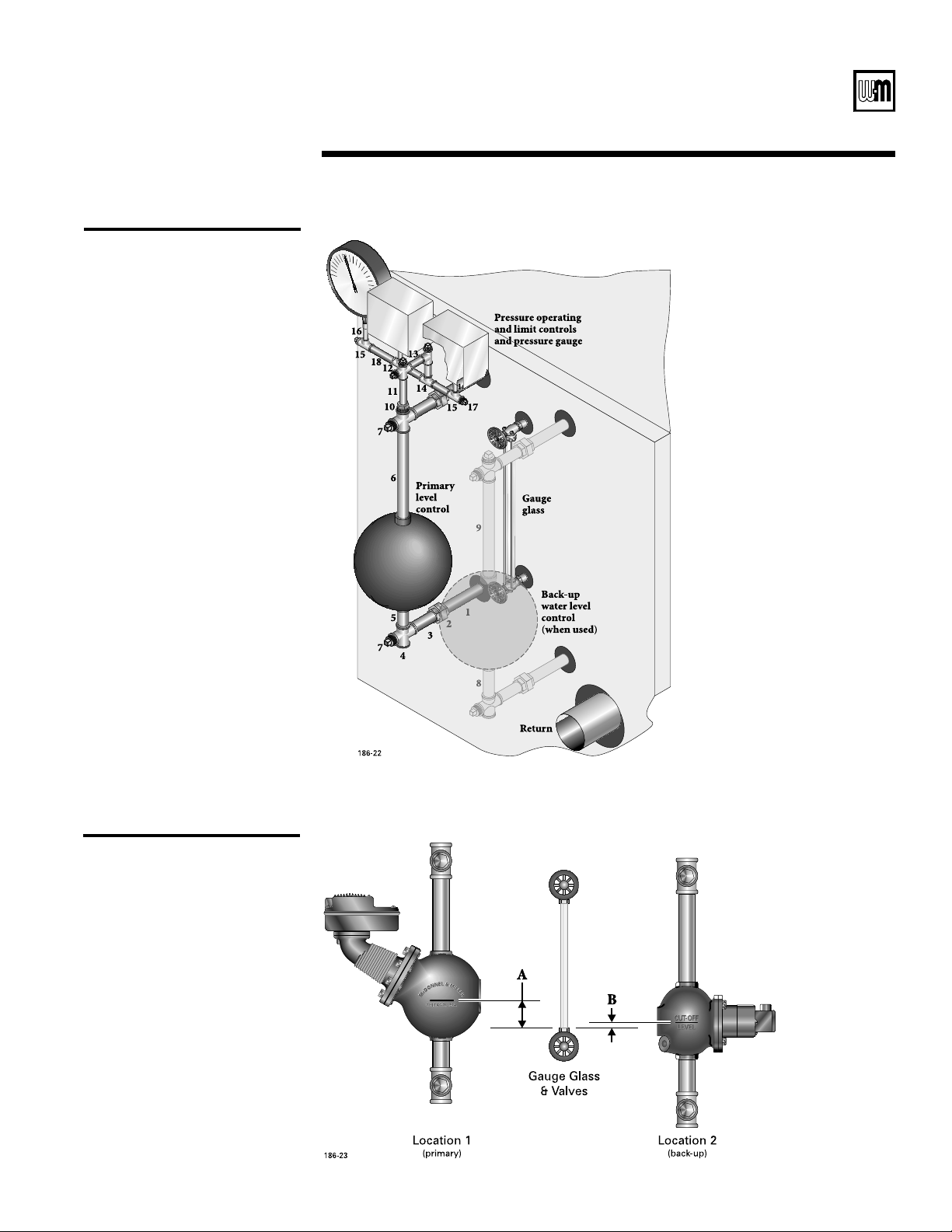
)NSTALLPRESSUREOPERATINGANDLIMITCONTROLSWATERLEVELCONTROLSGAUGEGLASSANDPRESSURE
gauge as in
Figures 22 and 23. Install relief valve(s), blowdown valve and other items as
given in
Figures 11a or 11bPAGESAND
2. Install water level control(s) as shown in Figures 22 and 23 and Table 4, below. If water
level control to be used is not shown in the table, install according to manufacturer’s in-
structions.
2
)NSTALLCONTROLSINTHETAPPINGSGIVENINFigures 11a or 11bPAGESAND
2. Low water cutoff for a water boiler:
A -USTBEINSTALLEDONANYWATERBOILERIFTHEBOILERISLOCATEDABOVERADIATIONLEVEL
B -AYBEREQUIred on water boilers by certain state, local or territorial codes or insurance
companies.
3. If a low water cutoff is used on a water boiler, use a control designed especially for water
installation. See control tapping locations in
Figures 11a and 11bPAGESANDFOR
location, or install in piping above boiler.
4. Dual limit control settings:
A ,OWSETACCORDINGTODESIGNREQUIREMENTS
B (IGH
o
higher than lowLIMIT
o
F maximum.
5. Install optional controls per control manufacturer’s instructions.
(
Location 1 A Location 2 B
Primary water level control
(Note 1)
(above bottom of
First backup water level
control (Note 1)
(above bottom of
61 and 63 1” –– ––
150S-MD, 93 (Notes 2 & 3) –– ––
51-2 and 51-S-2 (Note 2) –– ––
61 and 63 1 ½” 61 and 63 ½”
150S-MD, 93 (Notes 2 & 3) 61 and 63 ½”
51-2 and 51-S-2 (Note 2) 61 and 63 ½”
Part Number 550-141-186/0914
23
s)NSTALLATIONs3TART5Ps-AINTENANCEs0ARTS
1 .IPPLEvXv
2 5NIONv
3 .IPPLEvXv
4 #ROSSv
5 .IPPLEvXv
6 .IPPLEvXvUSEDONLY
WITH-ODELLWCOCUTTOlT
for other controls)
7 0LUGv
8 .IPPLEvXvNOTINCLUDED
9 .IPPLEvXCUTTOlTNOT
included
10 "USHINGvXÐv
11 .IPPLEÐvXv
12 #ROSSÐv
13 .IPPLEÐvXv
14 4EEÐv
15 4EEÐvXv
16 .IPPLEvXv
17 0LUGÐv
18 .IPPLEÐvXv
++
Steam boiler control
installation
+-
Steam boiler level control
locations (for Table 4)
)
=
=
>)
%9=
*?@@))
=

Part Number 550-141-186/0914
24
LGB
3ERIES'AS&IRED"OILER"OILER-ANUAL
9
(when used)
5SEANTIFREEZEESPECIALLYMADEFORHYDRONICSYSTEMS)NHIBITEDPROPYLENEGLYCOLISRECOM-
mended.
SOLUTIONPROVIDESPROTECTIONTOABOUT&
,OCALCODESMAYREQUIREABACKmOWPREVENTERORACTUALDISCONNECTFROMCITYWATERSUPPLY
$ETERMINEQUANTITYACCORDINGTOSYSTEMWATERCONTENT"OILERWATERCONTENTISLISTEDON
back cover. Remember to add in expansion tank water content.
5. Follow antifreeze manufacturer’s instructions.
@
#LOSEMANUALAIRVENTSDRAINCOCKSANDAUTOMATICAIRVENTIFUSED
2. Fill to correct system pressure. Correct pressure will vary with each application.
3. Open automatic air vent one turn, if used.
3TARTINGONTHELOWESTmOOROPENAIRVENTSONEATATIMEUNTILWATERSQUIRTSOUT#LOSEVENT
5. Repeat with remaining vents.
6. Refill to correct pressure.
(
#ONTINUALFRESHMAKEUPWATERWILLREDUCEBOILERLIFE-INERALSCANBUILDUPINSECTIONSREDUC-
ing heat transfer, overheating cast iron, and causing section failure.
)NHARDWATERAREASORLOWP(CONDITIONSBELOWCONSULTLOCALWATERTREATMENTCOMPANY
7a
Final Adjustments — water boilers
Do not use petroleum-based cleaning or sealing compounds in boiler system.
Severe boiler damage will occur.
Do not use automotive, ethylene glycol or undiluted antifreeze. Severe
personal injury, death or substantial property damage can result.

Part Number 550-141-186/0914
25
s)NSTALLATIONs3TART5Ps-AINTENANCEs0ARTS
7b
Final Adjustments — steam boilers
2
0ROVIDEvPIPINGFROMBOILERSKIMTAPPINGTOmOORDRAIN
2. Adjust waterline to midpoint of skim piping.
3. Fire boiler to maintain a temperature below steaming rate during skimming process.
4. Feed in water to maintain water level. Cycle burners to prevent rise in steam pressure.
5. Continue skimming until discharge is clear. This may take several hours.
6. Drain boiler. While boiler is warm but
NOT HOT, flush all interior surfaces under full
pressure until drain water runs clear.
7. Remove skim piping and plug tapping.
#LOSEDRAINCOCK&ILLWITHFRESHWATERTOWATERLINE3TARTBURNERSANDSTEAMFORMINUTES
to remove dissolved gases. Stop burners.
#HECKTRAPSANDAIRVENTSFORPROPEROPERATION
Cleaning
compounds
Clean all newly installed steam boilers to remove oil and grease. Failure to
properly clean can result in violent fluctuations of water level, water passing
into steam mains, or high maintenance costs on strainers, traps and vents.
Do not use petroleum-based cleaning or sealing compounds in boiler system.
Severe boiler damage will occur.
$ONOTlLLEXCEPTFORLEAKAGETESTSUNTILBOILERISREADYTOBElRED
2. Fill to normal waterline, halfway up gauge glass.
"OILERWATERP(TOISRECOMMENDED
4. Follow skimming procedure.
(
#ONTINUALFRESHMAKEUPWATERWILLREDUCEBOILERLIFE-INERALSCANBUILDUPINSECTIONSREDUC-
ing heat transfer, overheating cast iron, and causing section failure.
)NHARDWATERAREASORLOWP(CONDITIONSBELOWCONSULTLOCALWATERTREATMENTCOMPANY
Do not use petroleum-based cleaning or sealing compounds in boiler system.
Severe boiler damage will occur.

Part Number 550-141-186/0914
26
LGB
3ERIES'AS&IRED"OILER"OILER-ANUAL
8
4URNOPERATINGCONTROLTOOFF position or lowest position on dial. Be sure boiler has been
correctly filled with water.
2. Turn OFF electric power.
-AINSHUTOFFGASVALVEMUSTBECLOSEDFORATLEASTlVEMINUTESBEFORE
lighting to prevent minor personal injury or property damage.
3. Open manual main gas valve.
4. Adjust operating control to provide call for heat.
Your propane supplier mixes an odorant with the propane to make its pres-
ence detectable. In some instances, the odorant can fade, and any gas may
no longer have on odor.
Propane gas can accumulate at floor level. Smell near the floor for the gas
odorant or any unusual odor. Call your gas supplier immediately if you
suspect a leak. Do not attempt to light the pilot.
s 5SECAUTIONWHENATTEMPTINGTOLIGHTAPROPANEPILOT4HISSHOULDBE
DONEBYAQUALIlEDSERVICETECHNICIANPARTICULARLYIFPILOTOUTAGESARE
common.
s !SKYOURPROPANEDEALERORSERVICETECHNICIANTOPERIODICALLYCHECKTHE
odorant level of your gas.
s (AVEAQUALIlEDSERVICETECHNICIANINSPECTYOURBOILERANDSYSTEMAT
least yearly to make sure all gas piping is leak-tight.
Consult your propane supplier regarding installation of a gas leak detector.
There are some products on the market intended for this purpose. Your
supplier may be able to suggest an appropriate device.
5. Turn
ON electric power.
6. If boiler starts, go to Step 8.
If boiler fails to start, go to Step 7.
7. If boiler fails to start, check:
a. Loose connection or blown fuse?
b. Limit setting above boiler water temperature or pressure?
c. Gas turned on at meter?
d. Gas turned on at boiler?
e. Reset system by turning off and on main electrical switch.
f. If above fails to eliminate the trouble, refer to
Control Supplement.
-AKESUREBOILERGOESTHROUGHSEVERALNORMALOPERATINGCYCLES
4URNOPERATINGCONTROLTODESIREDSETTING
Propane odorant
can fade
Before lighting
pilot
8
Placing boiler in operation

Part Number 550-141-186/0914
27
s)NSTALLATIONs3TART5Ps-AINTENANCEs0ARTS
3YSTEMPROPERLYlLLEDWITHWATER
2. Automatic air vent, if used, open one turn (water boilers only)?
3. Air purged from system (water boilers only)?
4. Steam boilers properly skimmed?
5. Air purged from gas piping? Piping checked for leaks?
6. Are proper orifices installed? See
Control Supplements for orifice sizes.
7. Follow
Control Supplement and operating instruction label on boiler for proper start-up. Also refer to
Section 8, Placing boiler in operation, page 26.
8. Proper burner flame? Refer to
Check Pilot Burner Flames and Check Main Burner Flame, Section 10PAGE
4ESTLIMITCONTROL7HILEBURNERSAREOPERATINGMOVETHEINDICATOROFTHELIMITCONTROLBELOWACTUALBOILER
water temperature or pressure. Burners should go off. The circulator should continue to operate (water boilers
only). Raise the limit control above boiler water temperature or pressure and burners should reignite.
4ESTANYADDITIONALlELDINSTALLEDCONTROLS)FBOILERHASLOWWATERCUTOFFORADDITIONALHIGHLIMITOROTHER
controls, test for operation as outlined by the manufacturer. Burners should be operating and should go off
when controls are tested. When controls are reset, burners should reignite.
4ESTIGNITIONSHUTOFFDEVICE4URNOFFGASATMANUALMAINGASVALVE#ONNECT6!#LEADSACROSS06AND
-606TERMINALSONPILOTPROVINGCONTROLMODULE%STABLISHCALLFORHEAT0ILOTSOLENOIDVALVEWILLCLOSEWITHIN
SECONDSANDREMAINOFFFORMINIMUMMINUTESTHENRETRYFORIGNITION2ESETSYSTEMBYTURNINGOFFAND
on the main electrical switch.
,IMITCONTROLSETTODESIGNTEMPERATUREORPRESSUREREQUIREMENTSOFSYSTEM
&ORMULTIPLEZONESmOWADJUSTEDSOITISABOUTTHESAMEINEACHZONEWATERBOILERSONLY
"OILERCYCLEDWITHOPERATINGCONTROL2AISETOHIGHESTSETTING"OILERSHOULDGOTHROUGHNORMALSTARTUPCYCLE
Lower to lowest setting. Boiler should turn off.
-EASUREGASINPUTNATURALGASONLY
A /PERATEBOILERMINUTES
b. Turn off all other appliances.
c. At the natural gas meter, measure cubic feet of gas in ten seconds.
d. Calculate gas input:
s "TUHXX#&(
e. Btuh calculated should approximate input rating on rating plate.
#HECKMANIFOLDGASPRESSUREBYCONNECTINGAMANOMETERTOTHEDOWNSTREAMTESTTAPPINGONMAINGASVALVE
s -ANIFOLDGASPRESSUREvWCFOR
natural gas.
s -ANIFOLDGASPRESSUREvWCFORpropane gas.
3EVERALOPERATINGCYCLESOBSERVEDFORPROPEROPERATION
/PERATINGCONTROLSETTOTHEDESIGNREQUIREMENT
Installation and service certificate on this page completed?
!LLINSTRUCTIONSSHIPPEDWITHTHISBOILERREVIEWEDWITHOWNERORMAINTENANCEPERSONNELRETURNEDTOENVELOPE
and given to the owner or displayed near boiler?
Boiler model
Btuh input
Series
CP number
Date installed
____________
____________
____________
____________
____________
Installation instructions have been
followed.
#HECKOUTSEQUENCEHASBEENPER-
formed.
Information on this form is certified to
be correct.
Information received and left with
owner/maintenance personnel.
Installer
Address
Phone
Signature
___________________________
___________________________
___________________________
___________________________
___________________________
9
Check-out procedure — check off steps as completed
Proper orifices must be used. Failure to do so will cause severe personal injury, death or sub-
stantial property damage.
Part Number 550-141-186/0914
28
LGB
3ERIES'AS&IRED"OILER"OILER-ANUAL
10a
This product contains fiberglass jacket insulation and ceramic fiber materials in combustion
chamber lining or base panels in gas fired products. Airborne fibers from these materials have
been listed by the State of California as a possible cause of cancer through inhalation. The
combustion chamber lining or base insulation panels in this product contain ceramic fiber
materials. Ceramic fibers can be converted to cristobalite in very high temperature applica-
tions. The International Agency for Research on Cancer (IARC) has concluded, “Crystalline
SILICAINHALEDINTHEFORMOFQUARTZORCRISTOBALITEFROMOCCUPATIONALSOURCESISCARCINOGENIC
TOHUMANS'ROUPv
Suppliers of fiberglass wool products recommend the following precautions be taken when
handling these materials:
Precautionary measures
s !VOIDBREATHINGlBERGLASSDUSTANDCONTACTWITHSKINOREYES
s 5SE.)/3(CERTIlEDDUSTRESPIRATOR.4HISTYPEOFRESPIRATORISBASEDONTHE
/3(!REQUIREMENTSFORlBERGLASSWOOLATTHETIMETHISDOCUMENTWASWRITTEN
Other types of respirators may be needed depending on the job site conditions.
#URRENT.)/3(RECOMMENDATIONSCANBEFOUNDONTHE.)/3(WEBSITEATHTTP
WWWCDCGOVNIOSHHOMEPAGEHTML.)/3(APPROVEDRESPIRATORSMANUFACTURERSAND
phone numbers are also listed on this web site.
s 7EARLONGSLEEVEDLOOSElTTINGCLOTHINGGLOVESANDEYEPROTECTION
s !PPLYENOUGHWATERTOTHECOMBUSTIONCHAMBERLININGORBASEINSULATIONTOPREVENTAIR-
borne dust.
s 2EMOVECOMBUSTIONCHAMBERLININGORBASEINSULATIONFROMTHEBOILERANDPLACEITINA
plastic bag for disposal.
s /PERATIONSSUCHASSAWINGBLOWINGTEAROUTANDSPRAYINGMAYGENERATEAIRBORNElBER
CONCENTRATIONREQUIRINGADDITIONALPROTECTIONBAGFORDISPOSAL
s 7ASHPOTENTIALLYCONTAMINATEDCLOTHESSEPARATELYFROMOTHERCLOTHING2INSECLOTHESWASHER
thoroughly.
NIOSH stated First Aid.
s %YE)RRIGATEIMMEDIATELY
s "REATHING&RESHAIR
Label all wires prior to disconnection when servicing controls. Wiring errors can cause improper
and dangerous operation.
To avoid personal injury, death or property damage, keep boiler area clear and free from com-
BUSTIBLEMATERIALSGASOLINEANDOTHERmAMMABLEVAPORSANDLIQUIDS
Do not block flow of air to boiler. Incomplete combustion, flue gas spillage and carbon mon-
oxide emissions can cause severe personal injury, death or substantial property damage.
To avoid severe personal injury, death or substantial property damage — before servicing:
$ISCONNECTELECTRICALSUPPLY
2. Shut off gas supply.
3. Allow boiler to cool.
(AVEYOURBOILERINSPECTEDCLEANEDANDIFNECESSARYADJUSTEDONCEAYEARBYAQUALIlED
service agency.
Also refer to additional instructions shipped with boiler for specific control operation and
troubleshooting.
Verify proper operation after servicing. Failure to do so could result in boiler failure, causing
severe personal injury, death or substantial property damage.

Part Number 550-141-186/0914
s)NSTALLATIONs3TART5Ps-AINTENANCEs0ARTS
10b
Maintenance — minimum schedule
"
Repair leaks at
once
No petroleum-
based chemicals
#HECKFORLEAKSINBOILERANDPIPING)FFOUNDREPAIRATONCE
2. Visually inspect pilot and burner flames. Refer to Check pilot burner flames and Check
main burner flame, Section 10c
PAGE
3. Visually inspect venting system for blockage, deterioration or leakage. Refer to Inspect
venting system, Section 10c
PAGE
Leaks must be repaired at once. Failure to do so can cause damage to boiler,
resulting in substantial property damage.
Do not use petroleum-based sealing compounds in boiler system. Severe
damage to boiler will result.
$
Follow Annual shutdown procedure, Section 10cPAGE
#HECKTHATBOILERAREAISFREEFROMCOMBUSTIBLEMATERIALSGASOLINEANDOTHERmAMMABLE
VAPORSANDLIQUIDS
2. Check for and remove any obstruction to flow of combustion or ventilation air.
#HECKRELIEFVALVE2EFERTORELIEFVALVEMANUFACTURERSINSTRUCTIONSONRELIEFVALVETAG
2. Test low water cutoff, if used. Blowdown if low water cutoff is float type. Refer to low water
cutoff manufacturer’s instructions.
!NNUALSERVICECALLBYAQUALIlEDSERVICEAGENCY
2. Check burners and flueways and clean if necessary. Refer to Clean boiler heating surfaces
and Clean main burners, Section 10cPAGE
3. Follow procedure,
Section 8, Placing boiler in operation, page 26.
4. Visually inspect pilot and burner flames. Refer to Check pilot burner flames and Check
main burner flame, Section 10c
ONPAGE
5. Visually inspect venting system for blockage, deterioration or leakage. Refer to Inspect
venting system, Section 10c,
PAGE
6. Visually inspect base insulation. Refer to
Inspect base insulation, Section 10cPAGE
7. Check operation of low water cutoff, if used, and additional field-installed controls. Refer
to control manufacturer’s instructions.
8. Check that boiler area is free from combustible materials, gasoline and other flammable
VAPORSANDLIQUIDS
#HECKFORANDREMOVEANYOBSTRUCTIONTOmOWOFCOMBUSTIONORVENTILATIONAIR
,UBRICATECIRCULATORSIFREQUIREDPERCIRCULATORMANUFACTURERSINSTRUCTIONS
Part Number 550-141-186/0914
LGB
3ERIES'AS&IRED"OILER"OILER-ANUAL
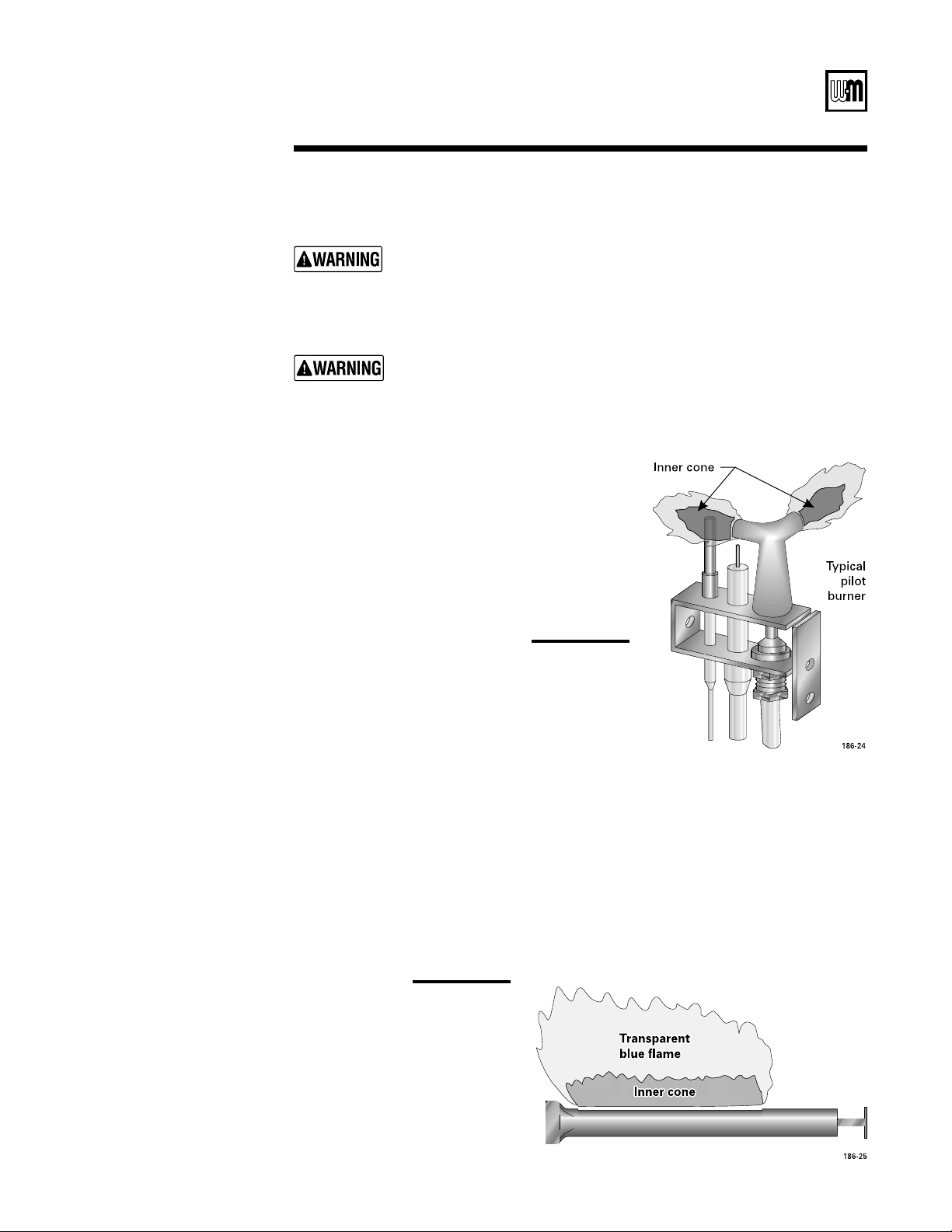
!
A
!
A
See Figure 24.
Proper pilot flame:
a. Blue flame.
b. Inner cone engulfing sensor.
2. Improper pilot flame:
a. Overfired — flames large and lifting or blowing
past sensor.
B 5NDERlREDmAMESSMALLSENSORNOTENGULFED
by inner cone.
See Figure 25.
#HECKMAINBURNERmAMESATLEASTONCEAMONTHDURINGHEATINGSEASON
2. Proper burner flame:
a. Yellow-orange streaks may appear - caused by dust.
3. Improper flame:
a. Overfired — Flames large.
b. Underfired — Flames small.
C ,ACKOFPRIMARYAIR9ELLOWTIPPINGONmAMESSOOTINGWILLOCCUR
+/
Typical pilot
+0
Typical main
10c
Maintenance — procedures
The boiler contains ceramic fiber and fiberglass materials. Use care when
handling these materials per instructions on page 28 of this manual. Failure
to comply could result in severe personal injury.
-AKESUREBASEINSULATIONISSECUREAGAINSTALLFOURBASEPANELS
If base insulation material is damaged or displaced, call service technician
immediately. Do not operate boiler. Operating boiler with damaged or
displaced base insulation can result in severe personal injury, death or
substantial property damage.

Part Number 550-141-186/0914
s)NSTALLATIONs3TART5Ps-AINTENANCEs0ARTS
)
#HECKVENTINGSYSTEMATLEASTONCEAMONTHDURINGHEATINGSEASON7ITHBOILERlRINGHOLD
candle or match below lower edge of draft hood “skirt”. If flame does not blow out, but burns
undisturbed, vent system is functioning properly. If flame blows out or flickers drastically,
vent system must be checked for obstructions or other causes of improper venting.
2. Inspect all parts of venting systems for deterioration from corrosion, physical damage,
sagging, etc. Correct all conditions found.
!
%XCESSIVESOOTINGINDICATESIMPROPERGASCOMBUSTION#HECKFORPROPERCOMBUSTIONANDMAKE
any necessary adjustments.
&OLLOWSHUTDOWNPROCEDURE
2. Remove back jacket panel and cleanout plates.
3. Remove burners from base of boiler. Follow
Clean main burners, below, to thoroughly
clean burners. Place newspaper in base of boiler to collect soot.
4. With a wire flue brush, clean between sections.
5. Remove paper and soot. Vacuum or brush base and surrounding area.
6. Replace cleanout plates and back jacket panel.
7. Replace main burners.
!
Seating burners
6ACUUMORBRUSHBURNERSTOREMOVEDUSTANDLINT
When replacing, burners must be seated in slots in back with openings
facing up. Front of burners must rest fully over main burner orifices.
Gas orifices must inject down center of burners. Failure to properly level
and seat burners will cause severe personal injury, death or substantial
property damage.
<@
#LOSEMAINSHUTOFFVALVE
2. Disconnect electric power supply.
3. Adjust operating control indicator to low setting.
4. Do not drain system unless exposure to freezing temperatures will occur. If antifreeze is
used with system, do not drain.
The boiler contains ceramic fiber and fiberglass materials. Use care when
handling these materials per instructions on page 28 of this manual.
Failure to comply could result in severe personal injury.
Base Insulation Table
Base Size
(Note 1)
Base Insulation Size
(Note 2)
44
55
AA
BB
CC
D A and K
E B and K
F A and J
G A and J
Notes:
1. Base Arrangement
Table, to determine base size for your
boiler.
2. Contains one (1) each front and back.
Part Number 550-141-186/0914
32
LGB
3ERIES'AS&IRED"OILER"OILER-ANUAL
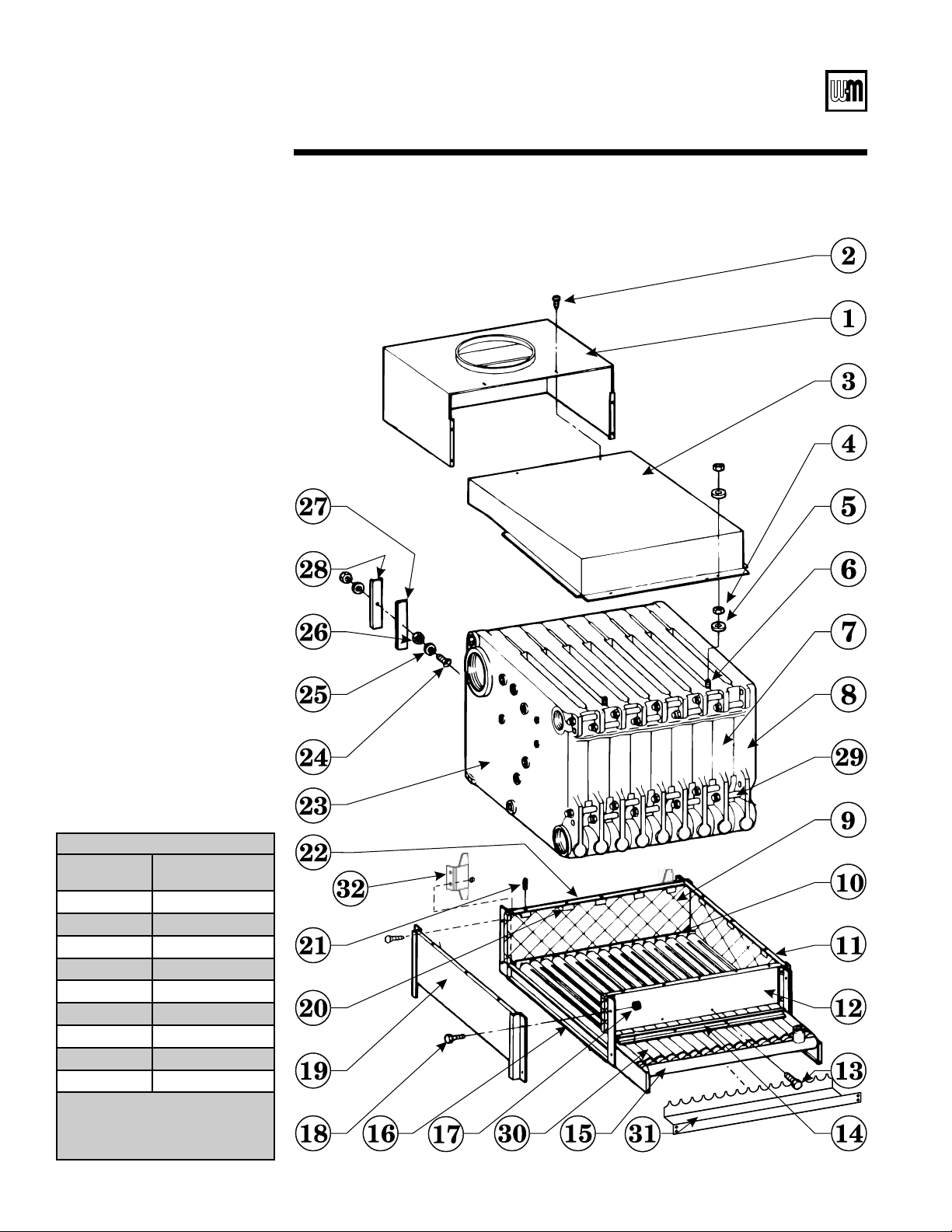
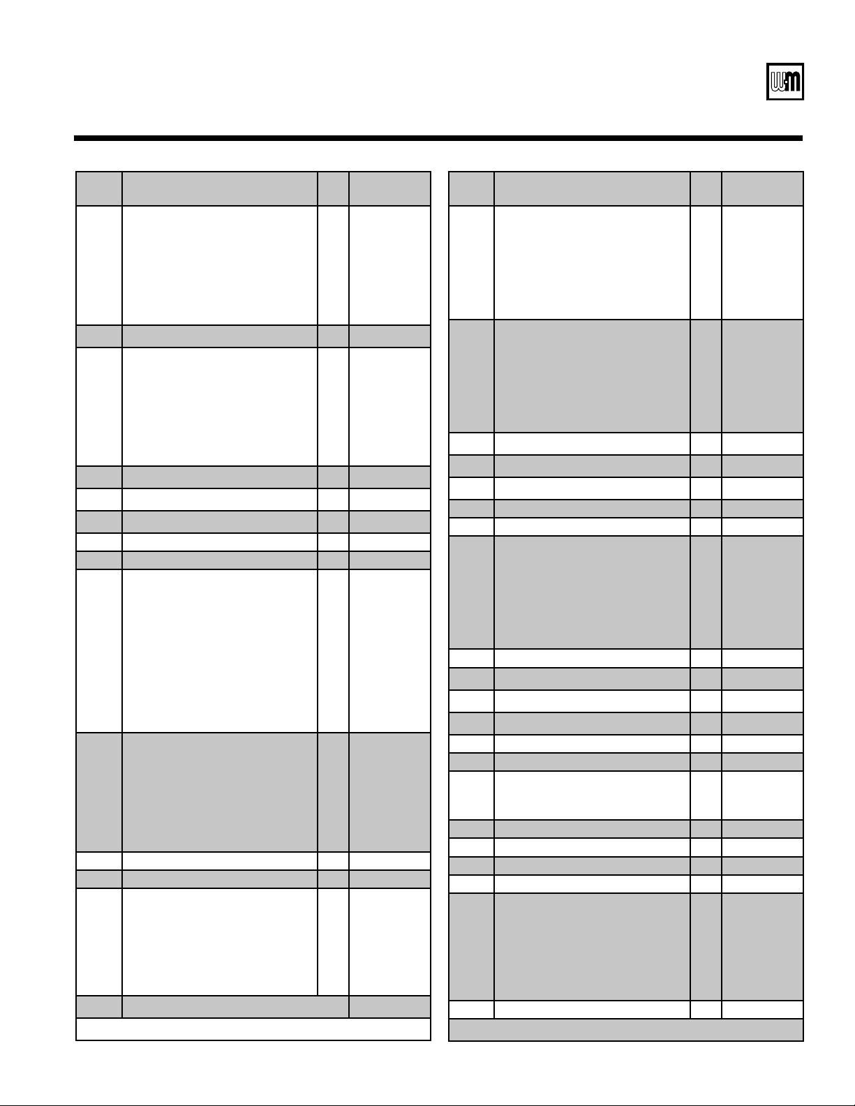
11
Replacement parts
Part Number 550-141-186/0914
33
s)NSTALLATIONs3TART5Ps-AINTENANCEs0ARTS
Item Description
Size
Weil-McLain
Part Number
1 Horizontal Draft Hood 4
5
A
B
C
D
E
F
G
443-300-098
443-300-099
443-300-100
443-300-101
443-300-102
443-300-103
443-300-104
443-300-105
443-300-106
2 Screw, Phillips #10 x1/2
*
3 Horizontal Collector Hood 4
5
A
B
C
D
E
F
G
450-019-858
450-019-859
450-019-851
450-019-852
450-019-853
450-019-854
450-019-855
450-019-856
450-019-857
4 !"$%'+;<
*
5 Washer, Plain 1/4- .312 x .734 x .065
*
6 ='+;<"';'
*
7 Intermediate Section (3318) 313-300-110
8 %>?L 313-300-111
9 Base Insulation (Front & Back) 4
5
A
B
C
J
K
591-221-330
591-221-331
591-221-332
591-221-333
591-221-334
591-221-335
591-221-336
591-221-337
591-221-338
591-221-339
591-221-340
591-221-341
591-221-342
591-221-343
10 Base Burner Rest 4
5
A
B
C
D
E
F
G
450-003-600
450-003-601
450-003-560
450-003-561
450-003-562
450-003-563
450-003-564
450-003-565
450-003-566
11,19 Base End Panel 383-300-165
Insulation 591-221-126
12 Base Front Panel 4
5
A
B
C
D
E
F
G
450-003-543
450-003-544
450-003-545
450-003-546
450-003-547
450-003-548
450-003-549
450-003-550
450-003-551
13 Screw, Hex Washer Head Slotted #10-32 x 3/8
*
*
Purchase at local supply house
Item Description
Size
Weil-McLain
Part Number
14 Base Access Shield 4
5
A
B
C
D
E
F
G
450-003-606
450-003-607
450-003-582
450-003-583
450-003-584
450-003-585
450-003-586
450-003-587
450-003-588
15 Manifold 4
5
A
B
C
D
E
F
G
591-125-908
591-125-909
591-125-910
591-125-911
591-125-912
591-125-913
591-125-914
591-125-915
591-125-916
16 Base Cross Tie
*
17 $QUV;XLY'+;<
*
18 Screw, Hex Head Cap 1/4-20 x 3/4
*
20 Base Insulation Support Clip 562-650-104
21 Roll Pin 1/8 x 2 562-930-236
22 Base Back Panel 4
5
A
B
C
D
E
F
G
450-003-598
450-003-599
450-003-553
450-003-554
450-003-555
450-003-556
450-003-557
450-003-558
450-003-559
23 XZ>?L'+ 313-300-109
24 ='+;<"';+
*
25 Washer, Plain 1/4-.312 x .734 x .065
*
26 !"$%'+;<
*
27 Insulation 591-221-115
28 Cleanout Plate 450-029-549
29
Draw Rod, 5/8-11 x 8
Washer, Plain 5/8-.656 x 1.312 x. 095
!"$%[\;''
560-134-480
*
*
30 Main Burner 512-200-050
6” Square Cut Seal 592-800-007
9” Square Cut Seal 592-800-005
%'!][<< 590-735-140
31 Burner Shield 4
5
A
B
C
D
E
F
G
450-003-350
450-003-352
450-003-354
450-003-356
450-003-358
450-003-360
450-003-362
450-003-364
450-003-366
32 ==Y%?XZ 450-003-614
* Purchase at local supply house
Boiler
Model
Number
Supply
Tappings
Return
Tappings
Dimensions in Inches No. of
Gas
Trains
Gas Connection Size
Natural and Propane (Note 1)
Draft Hood
Outlet(s)
No. Size No. Size A B C W 5" w.c.
Natural
7" w.c. Natural
11"-13" Propane
No. Size
LGB-4 2 6" 2 5" 18 9 -- 21
1 (1) 1"
(1) 1" 1 10"
LGB-5 2 6" 2 5" 23 11
1
/
2
-- 26
1 (1) 1"
(1) 1" 1 12"
LGB-6 2 6" 2 5" 28 14 -- 31
1 (1) 1
1
/
4
"
(1) 1" 1 12"
LGB-7 2 6" 2 5" 33 16
1
/
2
-- 36
1 (1) 1
1
/
4
"
(1) 1" 1 12"
LGB-8 2 6" 2 5" 38 19 -- 41
1 (1) 1
1
/
4
"
(1) 1" 1 14"
LGB-9 2 6" 2 5" 43 21
1
/
2
-- 46
1 (1) 1
1
/
4
"
(1) 1" 1 14"
LGB-10 2 6" 2 5" 48 24 -- 51
1 (1) 1
1
/
2
"
(1) 1
1
/
4
" 1 16"
LGB-11 2 6" 2 5" 53 26
1
/
2
-- 56
1 (1) 1
1
/
2
"
(1) 1
1
/
4
" 1 16"
LGB-12 2 6" 2 5" 58 29 -- 61
1 (1) 1
1
/
2
"
(1) 1
1
/
4
" 1 16"
LGB-13 2 6" 2 5" 63 16
1
/
2
30 66
2 (2) 1
1
/
4
"
(2) 1" 2 12"
LGB-14 2 6" 2 5" 68 19 32
1
/
2
71
2 (2) 1
1
/
4
"
(2) 1" 1 12"
2 6" 2 5" 1 14"
LGB-15 2 6" 2 5" 73 19 35 76
2 (2) 1
1
/
4
"
(2) 1" 2 14"
LGB-16 2 6" 2 5" 78 21
1
/
2
37
1
/
2
81
2 (2) 1
1
/
4
"
(2) 1" 2 14"
LGB-17 2 6" 2 5" 83 21
1
/
2
40 86
2 (2) 1
1
/
4
"
(2) 1" 2 14"
LGB-18 2 6" 2 5" 88 24 42
1
/
2
91
2 (1) 1
1
/
4
"
(1) 1" 1 14"
2 6" 2 5"
(1) 1
1
/
2
"
(1) 1
1
/
4
" 1 16"
LGB-19 2 6" 2 5" 93 24 45 96
2 (2) 1
1
/
2
"
(2) 1
1
/
4
" 2 16"
LGB-20 2 6" 2 5" 98 26
1
/
2
47
1
/
2
101
2 (2) 1
1
/
2
"
(2) 1
1
/
4
" 2 16"
LGB-21 2 6" 2 5" 103 26
1
/
2
50 106
2 (2) 1
1
/
2
"
(2) 1
1
/
4
" 2 16"
LGB-22 2 6" 2 5" 108 29 52
1
/
2
111
2 (2) 1
1
/
2
"
(2) 1
1
/
4
" 2 16"
LGB-23 2 6" 2 5" 113 29 55 116
2 (2) 1
1
/
2
"
(2) 1
1
/
4
" 2 16"
Note 1: Gas train sizes shown are gas connection sizes. Gas piping from meter to boiler to be sized according to local utility requirements.
Part Number 550-141-186/0914
34
LGB
3ERIES'AS&IRED"OILER"OILER-ANUAL
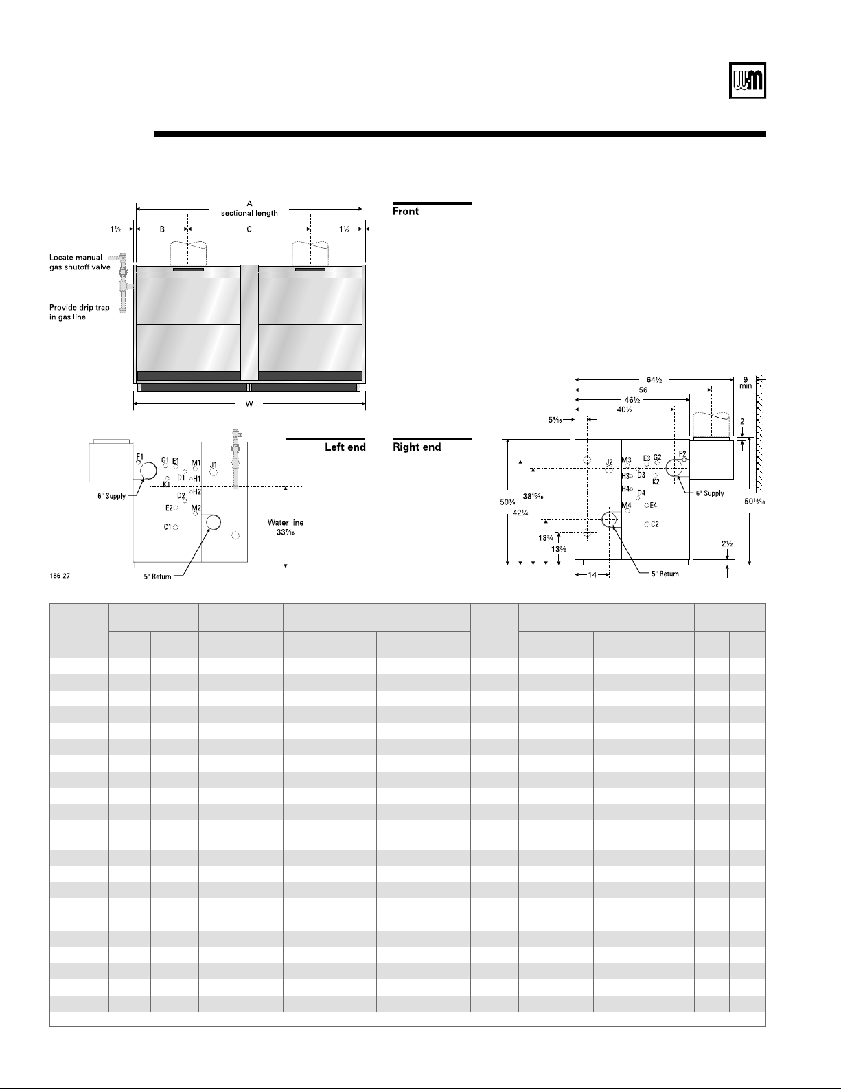
12
Dimensions

Part Number 550-141-186/0914
35
s)NSTALLATIONs3TART5Ps-AINTENANCEs0ARTS
13
Equipment — standard and optional
2%
@
#AST)RON3ECTIONS
2. Insulated Steel Jacket
3. Aluminized Steel Collector Hood(s) and Draft Hood(s)
4. Factory Packaged Burner-Base Assembly(ies)
s /NE0IECE!LUMINIZED3TEEL"URNERS
s 'AS$ISTRIBUTION-ANIFOLD
s !LUMINIZED3TEEL"ASE0ANELS
s (IGH4EMPERATURE)NSULATION"OARD0ANELS
5. Factory Pre-piped Gas Control Assembly(ies) - 24 volt
s -ANUAL-AIN3HUTOFF'AS6ALVE,'"THROUGH,'"ONLY
s 3AFETY'AS6ALVE,'"THROUGH,'"ONLY
s #OMBINATION4WOSTAGE'AS6ALVEAND0RESSURE2EGULATOR,'"THROUGH,'"
only)
s #OMBINATION'AS6ALVEWITH0ILOT4APPING,'"AND,'"ONLY
s (IGH'AS0RESSURE3WITCHES,'"THROUGH,'"ONLY
s #ONTROL4RANSFORMERVOLT
6. Junction Box
7&'&LAME2ECTIlCATION%LECTRONIC#ONTROL3YSTEM,'"THROUGH,'"ONLYPER
base)
s 0REWIRED #ONTROL0ANEL WITH4ERMINAL "LOCK AND 0ILOT AND-AIN&LAME)GNITION
#ONTROL-ODULESWITH)NTEGRAL3PARK'ENERATORS
s )NTERMITTENT%LECTRONIC)GNITION0ILOT3YSTEM
s %LECTRONICALLY3UPERVISED0ILOT"URNER
s -AIN&LAME3ENSOR
8. Intermittent Ignition Control System (LGB-4 and LGB-5 only)
s )NTERMITTENT)GNITION#ONTROL-ODULE
s %LECTRONICALLY3UPERVISED0ILOT"URNER
s 7IRE(ARNESS
(
#OMBINATION/PERATINGAND(IGH,IMIT4EMPERATURE#ONTROL,'"THROUGH,'"
only)
/PERATING4EMPERATURE#ONTROL,'"THROUGH,'"ONLY
(IGH,IMIT4EMPERATURE#ONTROL,'"THROUGH,'"ONLY
4. Combination Pressure/Temperature Gauge
03)!3-%3AFETY2ELIEF6ALVE3IDE/UTLET03)WORKINGPRESSURE
"UILTIN!IR%LIMINATOR
7. Wiring Harness/Junction Box and Pre-wired Flexible Conduit
8. Probe-type Low Water Cutoff (Packaged units only)
2
/PERATING0RESSURE#ONTROL
2. High Limit Pressure Control
3. Pressure Gauge
4. Siphon
5. Gauge Cocks, Glass and Guards
!3-%3AFETY6ALVE3IDE/UTLET
7. Float-type Low Water Cutoff
8. Wiring Harness/Junction Box and Pre-wired Flexible Conduit
B%
v)NSPECTION4APPINGSWITH"RASS0LUGSONEPERSECTION
2. Water Level Controls
3. Pilot Pressure Regulator
,OW(IGH,OW&IRING,'"THROUGH,'"ONLY3TAGE&IRING,'"THROUGH,'"
ONLYBASEONHIGHlREBASEONHIGHlRELOWHIGHLOWLOW

Part Number 550-141-186/0914
36
LGB
3ERIES'AS&IRED"OILER"OILER-ANUAL
14
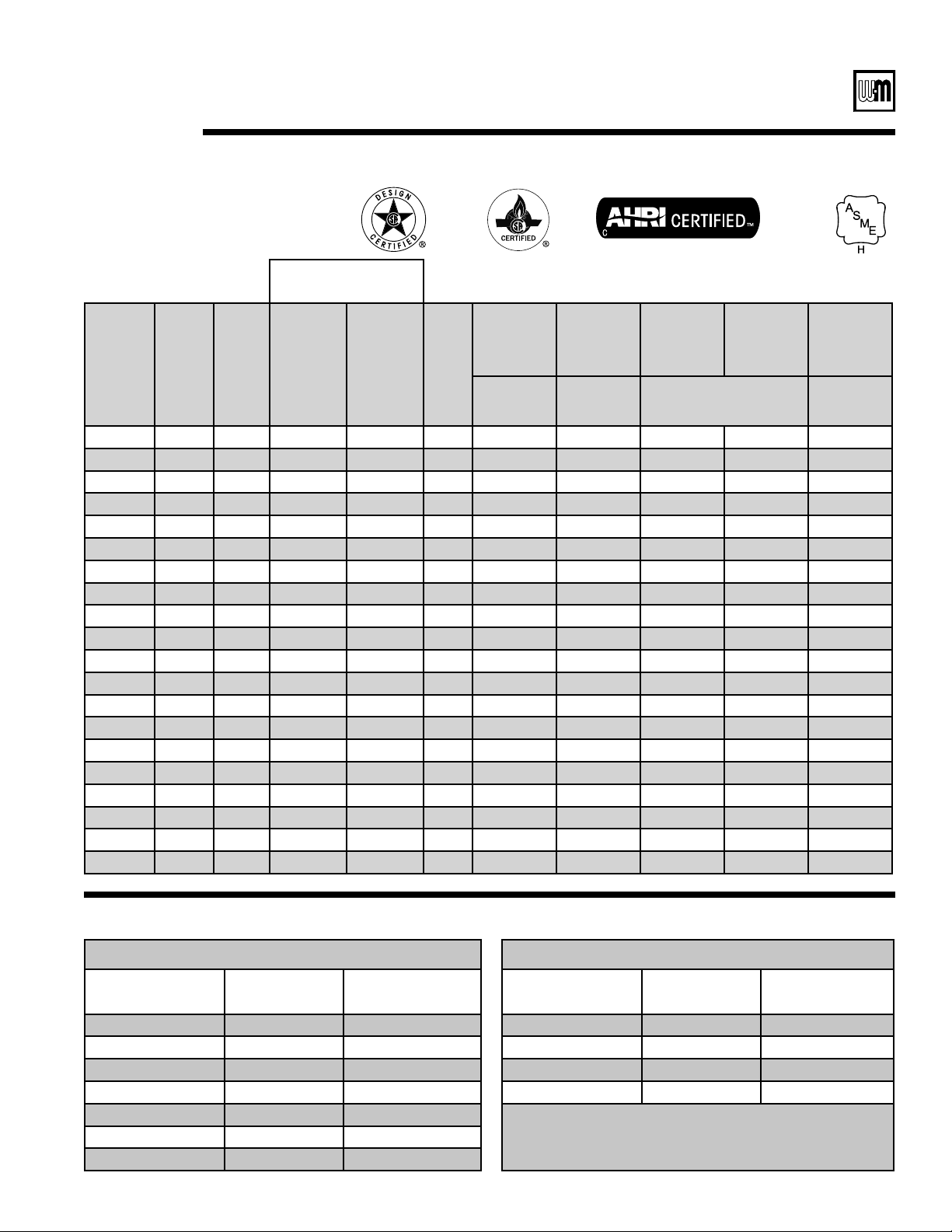
Ratings - Steam
:
1 Add to boiler number “S” for Steam, “W” for Water.
2 -"(THOUSANDSOF"45HOUR
3 .ET!(2)RATINGSAREBASEDONNETINSTALLEDRADIATIONOFSUFlCIENT
QUANTITYFORBUILDINGREQUIREMENTS$ONOTADDONFORNORMAL
PIPINGANDPICKUP7ATERBOILERSARERATEDATPSIGMAXIMUM
working pressure. Water ratings are based on piping and pickup
ALLOWANCEOF
Additional allowance should be made for gravity hot water sys-
tems or unusual piping and pickup loads. Ratings shown are for
ELEVATIONSUPTOFEET&ORRATINGSABOVEFEETREDUCE
ATRATEOFPERCENTPERFEETABOVESEALEVEL
4 3LINGLENGTHISFEETPERBOILER
5 !TWENTYFOOTCHIMNEYHEIGHTMAYBEUSEDINMOSTCASESBASEDONUSINGASIXFOOT
(6’) length of connector for breeching of the size shown from the nearest draft hood
OUTLETTOTHECHIMNEYORVENTWITHNOT MORETHANONE STANDARDSLOPINGTYPE
ELBOW#ONSULTTHE.ATIONAL&UEL'AS#ODE!.3):FORACTUALSIZING)FINDIVIDUAL
vertical vents are to be used, each vent diameter should be the same size as the respective
draft hood outlet and the height may be reduced to five feet (5’) measured above the
draft hood outlet.
(Note 3)
Boiler
Model
Number
(Note 1)
Heating
Medium
Input
MBH
(Note 2)
Gross
Output
MBH
(Note 2)
Net
Rating
Steam
MBH
(Note 2)
Boiler
H.P.
Sq. Ft.
Steam
Boiler Water
Content
Gallons
Approx.
Shipping
Weight
Assembled
Block
Weight
Complete
Packaged
Boiler
Weight
Chimney
Breeching
Size (I.D.)
Steam
(to
Waterline)
Water-
Gallons lbs.
Models PLGB
(Note 4)
Inches
(Note 5)
LGB-4 Steam 400 312 234 9.7 975 23.2 36.5 1185 975 1600 10
LGB-5 Steam 520 409 307 12.6 1279 28.9 45.6 1455 1200 1800 12
LGB-6 Steam 650 514 386 15.7 1607 34.6 54.7 1725 1425 2000 12
LGB-7 Steam 780 619 464 18.9 1936 40.3 63.9 2005 1650 2300 12
LGB-8 Steam 910 724 543 22.0 2264 46.0 73.0 2290 1900 2500 14
LGB-9 Steam 1040 829 622 25.2 2591 51.9 82.1 2560 2125 2800 14
LGB-10 Steam 1170 934 701 28.3 2918 57.6 91.2 2800 2375 3100 16
LGB-11 Steam 1300 1039 779 31.5 3246 63.4 100.4 3105 2600 3300 16
LGB-12 Steam 1430 1144 858 34.6 3576 69.1 109.5 3365 2850 3500 16
LGB-13 Steam 1560 1239 929 37.8 3868 74.9 118.6 3785 3100 4100 16
LGB-14 Steam 1690 1344 1015 40.9 4228 80.7 127.7 4085 3330 4300 16
LGB-15 Steam 1820 1449 1102 44.0 4592 86.4 136.9 4355 –– –– 16
LGB-16 Steam 1950 1552 1188 47.2 4950 92.2 146.0 4725 –– –– 17
LGB-17 Steam 2080 1658 1276 50.3 5316 98.0 155.1 4975 –– –– 17
LGB-18 Steam 2210 1764 1364 53.5 5682 103.6 164.2 5270 –– –– 18
LGB-19 Steam 2340 1867 1448 56.6 6034 109.5 173.4 5540 –– –– 18
LGB-20 Steam 2470 1974 1533 59.8 6384 115.3 182.5 5820 –– –– 19
LGB-21 Steam 2600 2077 1613 62.9 6720 121.0 191.6 6080 –– –– 19
LGB-22 Steam 2730 2184 1696 66.1 7065 126.8 201.2 6365 –– –– 19
LGB-23 Steam 2860 2288 1776 69.2 7402 132.5 209.8 6625 –– –– 20
Part Number 550-141-186/0914
37
s)NSTALLATIONs3TART5Ps-AINTENANCEs0ARTS
14
Ratings - Water
(Note 3)
Boiler
Model
Number
(Note 1)
Heating
Medium
Input
MBH
(Note 2)
Gross
Output
MBH
(Note 2)
Net
Rating
Water
MBH
(Note 2)
Boiler
H.P.
Boiler Water
Content
Gallons
Approx.
Shipping
Weight
Assembled
Block
Weight
Complete
Packaged
Boiler Weight
Chimney
Breeching
Size (I.D.)
Gallons lbs.
Models PLGB
(Note 4)
Inches
(Note 5)
LGB-4-W Water 400 322 280 9.7 36.5 1185 975 1600 10
LGB-5-W Water 520 419 364 12.6 45.6 1455 1200 1800 12
LGB-6-W Water 650 523 455 15.7 54.7 1725 1425 2000 12
LGB-7-W Water 780 628 546 18.9 63.9 2005 1650 2300 12
LGB-8-W Water 910 737 641 22.0 73.0 2290 1900 2500 14
LGB-9-W Water 1040 843 733 25.2 82.1 2560 2125 2800 14
LGB-10-W Water 1170 950 826 28.3 91.2 2800 2375 3100 16
LGB-11-W Water 1300 1057 919 31.5 100.4 3105 2600 3300 16
LGB-12-W Water 1430 1165 1013 34.6 109.5 3365 2850 3500 16
LGB-13-W Water 1560 1273 1107 37.8 118.6 3785 3100 4100 16
LGB-14-W Water 1690 1381 1201 40.9 127.7 4085 3330 4300 16
LGB-15-W Water 1820 1489 1295 44.0 136.9 4355 –– –– 16
LGB-16-W Water 1950 1597 1389 47.2 146.0 4725 –– –– 17
LGB-17-W Water 2080 1708 1485 50.3 155.1 4975 –– –– 17
LGB-18-W Water 2210 1817 1580 53.5 164.2 5270 –– –– 18
LGB-19-W Water 2340 1926 1675 56.6 173.4 5540 –– –– 18
LGB-20-W Water 2470 2035 1770 59.8 182.5 5820 –– –– 19
LGB-21-W Water 2600 2207 1919 62.9 191.6 6080 –– –– 19
LGB-22-W Water 2730 2318 2016 66.1 201.2 6365 –– –– 19
LGB-23-W Water 2860 2428 2111 69.2 209.8 6625 –– –– 20
Derate multipliers for low natural gas supply pressures
For boilers Equipped for 7.0” water column (w.c.) For boilers Equipped for 5.0” water column (w.c.)
Actual Inlet Natural Gas
Pressure (Note 1)
Derate Multiplier
Resulting Manifold Gas
Pressure
Actual Inlet Natural Gas
Pressure (Note 1)
Derate Multiplier
Resulting Manifold
Gas Pressure
6.00” w.c. 0.92 3.00” w.c. 4.75” w.c. 0.96 3.20” w.c.
5.50” w.c. 0.88 2.70” w.c. 4.50” w.c. 0.94 3.10” w.c.
5.00” w.c. 0.84 2.50” w.c. 4.25” w.c. 0.91 2.90” w.c.
4.75” w.c. 0.81 2.30” w.c. 4.00” w.c. 0.89 2.80” w.c.
4.50” w.c. 0.80 2.20” w.c.
Note 1
^_`?g?Z
?Z;L?j
4.25” w.c. 0.77 2.05” w.c.
4.00” w.c. 0.75 1.95” w.c.

Part Number 550-141-186/0914
38
LGB
3ERIES'AS&IRED"OILER"OILER-ANUAL
Notes

Part Number 550-141-186/0914
s)NSTALLATIONs3TART5Ps-AINTENANCEs0ARTS
Notes

Part Number 550-141-186/0914
LGB
3ERIES'AS&IRED"OILER"OILER-ANUAL
Weil-McLain
500 Blaine Street
Michigan City, IN 46360-2388
htt
p
://www.weil-mclain.com