WARNING:
TO AVOID RISK OF ELECTRICAL SHOCK, BE SURE TO SHUT OFF
POWER BEFORE INSTALLING OR SERVICING THIS FIXTURE.
NOTES: 1. Before installing, consult local electrical codes for wiring and grounding requirements.
2. Read and save these instructions.
ASSEMBLY AND INSTALLATION
INSTRUCTIONS
LK55512
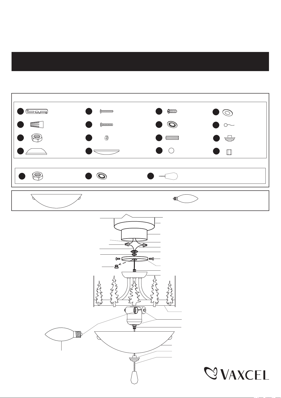
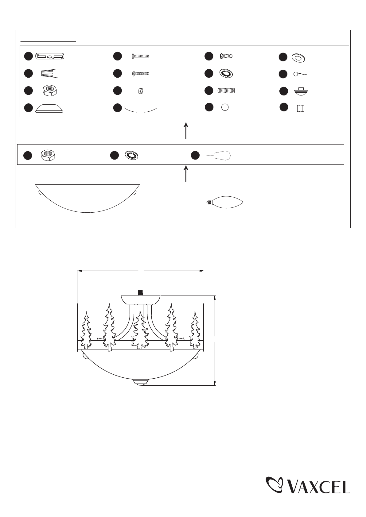
Hardware Package (included): For Ceiling Light
Hardware Package (included): For Light Kit
Mounting Screw
X2
Green Ground
Screw X1
Washer
X2
Lock Nut
X2
Hex Nut
X2
Threaded Pipe
X1
Top Cap
X1
Mounting Strap
X1
AA
EE II
BB
FF
JJ
CC
GG KK
LL
DD
HH
Wire Connector
X3
Fixture Mounting
Screw X2
Canopy
X1
Ball Nut
X2
MM
Ground Pad
X1
NN
Fixture Ground
Wire X1
Final
X1
OO
Coupling
X1
PP
Washer
X1
Hex Nut
X1
SS
RR
QQ
Wood Bead
X1
190509
Glass Shade (1 PC) Candelabra 4W LED Blub (2 PCS)
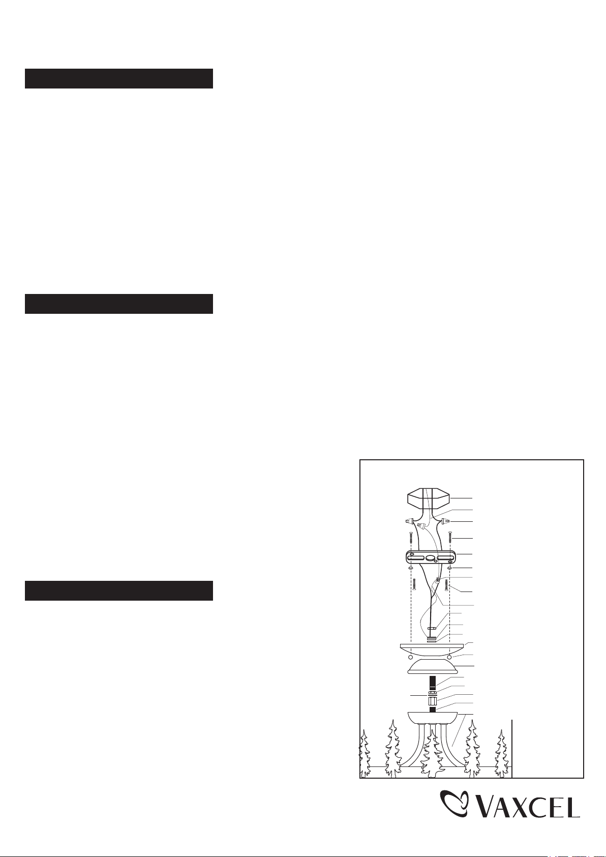
Center Plug
Black or Blue Wire
Wire Connector (BB)
Black Wire
Washer (RR)
White W
Hex Nut (QQ)
ire
White Wire
Switch Box
Motor
Threaded Pipe (-a)
Switch Box Cover
Cap
Switch Box Screw
Threaded Pipe (-b)
Glass Shade
Pan
Socket Set
Wood Bead (SS)
Final (OO)
Candelabra Base 4W LED Bulb
(included)
Turn on the power at fuse or circuit box.
Turn off the power at fuse or circuit box.
Turn off the power at fuse or circuit box.
Installation Steps
190509
1. Remove the switch box cover from the switch box of the fan by loosing the three switch box screws.
2. Unscrew the center plug from the switch box cover and discard it.
3. Thread the fixture wire through the switch box cover.
4. Attach threaded pipe (-a) of the light kit to the switch box cover, then secure it with a washer (RR) and hex nut (QQ).
5. Cut the redundant wires if necessary. Pull out the wires from the switch box. Make wire connections using the
wire connectors (BB):
---The black wire from the fixture to the black (or blue) wire from the switch box.
---The white wire from the fixture to the white wire from the switch box.
Carefully put the wires back into the switch box.
6. Attach the switch box cover back to the switch box using the three switch box screws.
7. Install bulbs (included). See relamping label at socket area or packaging for maximum allowed wattage.
8. Thread the pull chain through the glass shade and the finial (OO). Carefully attach the glass shade to the pan by
inserting threaded pipe (-b), then secure it with the finial (OO).
9. Turn on the power at the main fuse or circuit breaker box. (You can control the light with the wood bead (SS).)
Mounting Parts for Ceiling Light
Outlet Box
House Ground Wire
Wire Connector (BB)
Fixture Mounting Screw (FF)
Mounting Strap (AA)
Lock Nut (GG)
Green Ground Screw (II)
Mounting Screw (EE)
Fixture Ground Wire (NN)
Hex Nut (CC)
Ground Pad (MM)
Washer (JJ)
Canopy (HH)
Ball Nut (LL)
Top Cap (DD)
Threaded Pipe (-c) (KK)
Hex Nut (CC)
Washer (JJ)
Coupling (PP)
Threaded Pipe (-d)
Fixture
For Ceiling Light:
For Light Kit:
1. Take out the coupling (PP), two hex nuts (CC), washer (JJ), threaded pipe (-c) (KK), top cap (DD), canopy (HH),
washer (JJ) and ground pad (MM) from the hardware package for ceiling light.
2. Secure the coupling (PP) to threaded pipe (-d), then threaded pipe (-c) (KK) into the coupling (PP) and secure it
with a washer (JJ) and hex nut (CC).
3. Attach the top cap (DD) with the open side facing downward and the canopy (HH) with the open side facing upward to
the fixure by inserting threaded pipe (-c) (KK), then secure them with a washer (JJ), ground pad (MM) and hex nut (CC).
4. Attach two fixture mounting screws (FF) to the mounting strap (AA), then secure them with two lock nuts (GG). Adjust
the length of the fixture mounting screws (FF) if necessary.
5. Attach the mounting strap (AA) to the outlet box by using two mounting screws (EE).
6. Pull out the outlet wires and the house ground wire from the outlet box. Make wire connections using the wire
connectors (BB):
---The black wire from fixture to the black wire from the outlet box.
---The white wire from fixture to the white wire from the outlet box.
---Attach the fixture ground wire (NN) to the mounting strap (AA) with
the green ground screw (II) . Then connect it to the house ground
wire with a wire connectors (BB).
Carefully put the wires back into the outlet box.
7. Attach the canopy (HH) to the mounting strap (AA) by inserting two
fixture mounting screws (FF), then secure them with the ball nuts (LL).
8. Follow steps 7~9 as for Light Kit.
The following parts are available for re-order if damaged or missing.
Spare Parts List:
Assembly Kit
6127MM
(1 SET)
Assembly Kit
6126MM
(1 SET)
Glass Shade
8096CD
(1 PC)
Candelabra 4W LED Blub
8096LD (2 PCS)
190509
Washer
X1
Hex Nut
X1
SS
RR
QQ
Wood Bead
X1
A
B
A : 11-1/2”
B: 8”
Mounting Screw
X2
Green Ground
Screw X1
Washer
X2
Lock Nut
X2
Hex Nut
X2
Threaded Pipe
X1
Top Cap
X1
Mounting Strap
X1
AA
EE II
BB
FF
JJ
CC
GG KK
LL
DD
HH
Wire Connector
X3
Fixture Mounting
Screw X2
Canopy
X1
Ball Nut
X2
MM
Ground Pad
X1
NN
Fixture Ground
Wire X1
Final
X1
OO
Coupling
X1
PP