Loading ...
2
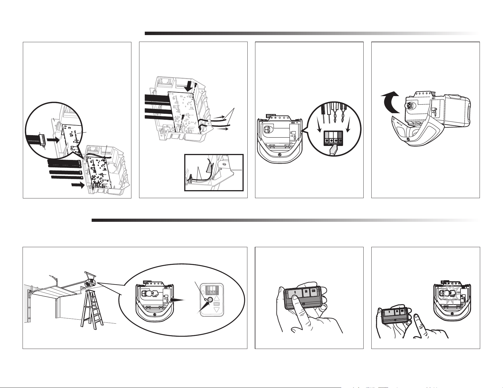
Install new receiver logic board
3
3.3 Reinsert the wires.
Door control wires:
• white wire into the white terminal.
• white/red wire into the red terminal.
Safety sensor wires:
• white wires into the white terminal.
• white/black wires into the
grey terminal.
NOTE: A test of the safety reverse system is necessary for safe operation.
To insert or remove the
wires from the terminal,
push in the tab with a
screwdriver tip.
1
Programming
1.1 Press and release the Learn button on the garage door opener. The Learn indicator light
will glow steadily for 30 seconds.
1.2 Within 30 seconds, press and hold the
button on the remote control.
1.3 Release the button when the garage
door opener light blinks. It has learned
the code. If light bulbs are not installed,
two clicks will be heard.
Program a remote control using the learn button
Learn
Indicator
Light
Yellow Learn
Button
3.4 Install the light lens by aligning with
the hinges and snapping into place.
Reconnect power.
NOTE: When installing the light lens, ensure the antenna
wires are hanging straight down.
Red
White
White
Grey
To program the Wi-Fi garage door opener to your network refer to your owner’s manual.
3.2 Insert the antenna wires through
the holes in the end panel. Snap the
receiver logic board into place on the
end panel and fasten with screws.
NOTE: Some models
will require the short
antenna wire to be
placed in the traps of
the end panel.
Antenna wires
Antenna
wires
3.1 Connect the wire harnesses to the
new receiver logic board. When
reconnecting the wire harness, be sure
the tabs on the wire harness are facing
the end panel, not the logic board.
Logic Board
Wire Clip
End Panel
Wire
Harness
Tabs
NOTE: If your logic board
has a wire clip, use the
wire clip to hold wires to
the logic board.
Loading ...
Loading ...
Loading ...