Owner's Manual
IC..FTSMnWl
ROTARY LAWN MOWER
6.5 Horsepower
Power-Propelled
21" Rear Discharge
Model No.
917.377663
• EspaSol, p. 19
CAUTION:
Read and follow all
Safety Rules and Instructions
before operating this equipment
Sears, Roebuck and Co., Hoffman Estates, IL 60179 U.S.A.
Visit our Craftsman website: www.sears.com/craftsman
Warranty ................................................... 2
Safety Rules .......................................... 2-4
Product Specifications .............................. 4
Assembly / Pre-Operation ........................ 6
Operation ............................................ 7-10
Maintenance Schedule ........................... 11
Maintenance ...................................... 11-14
Service and Adjustments ................... 14-15
Storage .............................................. 15-16
Troubleshooting ................................. 17-18
Repair Parts ....................................... 35-43
Sears Service .......................... Back Cover
LIMITED TWO YEAR WARRANTY ON CRAFTSMAN POWER MOWER
For two years from date of purchase, when this Craftsman Lawn Mower is maintained,
lubricated, and tuned up according to the operating and maintenance instructions in the
owner's manual, Sears will repair free of charge any defect in material or workmanship.
If this Craftsman Lawn Mower is used for commercial or rental purposes, this warranty
applies for only 90 days from the date of purchase.
This Warranty does not cover:
• Expendable items which become worn during normal use, such as rotary mower
blades, blade adapters, belts, air cleaners and spark plug.
• Repairs necessary because of operator abuse or negligence, including bent crank-
shafts and the failure to maintain the equipment according to the instructions con-
tained in the owner's manual.
Warranty service is available by returning the Craftsman power mower to the nearest Sears
Parts & Repair Center in the United States. This warranty applies only while this product
is used in the United States.
This Warranty gives you specific legal rights, and you may also have other rights which
vary from state to state.
Sears, Roebuck And Co., D/817 WA, Hoffman Estates, IL 60179
IMPORTANT: This cutting machine is capable of amputating hands and feet and throw-
ing objects. Failure to observe the following safety instructions could result in serious
injury or death.
_¢l,Look for this symbol to point out
important safety precautions. It means
CAUTION!H BECOME ALERT!H
YOUR SAFETY IS INVOLVED.
• I,WARNING: In order to prevent ac-
cidental starting when setting up, trans-
porting, adjusting or making repairs,
always disconnect spark plug wire and
place wire where it cannot come into
contact with the spark plug.
_,WARNING: Engine exhaust, some of its
constituents, and certain vehicle compo-
nents contain or emit chemicals known
to the State of California to cause cancer
and birth defects or other reproductive
harm.
2
Ai_WARNING: Battery posts, terminals and
related accessories contain lead and lead
compounds, chemicals known to the State
of California to cause cancer and birth
defects or other reproductive harm. Wash
hands after handling.
• 1,CAUTION: Muffler and other engine
parts become extremely hot during
operation and remain hot after engine has
stopped. To avoid severe burns on contact,
stay away from these areas.
I. GENERAL OPERATION
• Read, understand, and follow all
instructions on the machine and in the
manual(s) before starting. Be thoroughly
familiar with the controls and the proper
use of the machine before starting.
• Do not put hands or feet near or under
rotating parts. Keep clear of the dis-
charge opening at all times.
• Only allow responsible individuals, who
are familiar with the instructions, to oper-
ate the machine.
• Clear the area of objects such as rocks,
toys, wire, bones, sticks, etc., which
could be picked up and thrown by the
blade.
• Be sure the area is clear of other people
before mowing. Stop machine if anyone
enters the area.
• Do not operate the mower when bare-
foot or wearing open sandals. Always
wear substantial foot wear.
• Do not pull mower backwards unless
absolutely necessary. Always look down
and behind before and while moving
backwards.
• Do not operate the mower without
proper guards, plates, grass catcher or
other safety protective devices in place.
• See manufacturer's instructions for
proper operation and installation of
accessories. Only use accessories ap-
proved by the manufacturer.
• Stop the blade(s) when crossing gravel
drives, walks, or roads.
• Stop the engine (motor) whenever you
leave the equipment, before cleaning the
mower or unclogging the chute.
• Shut the engine (motor) off and wait until
the blade comes to complete stop before
removing grass catcher.
• Mow only in daylight or good artificial
light.
• Do not operate the machine while under
the influence of alcohol or drugs.
• Never operate machine in wet grass.
Always be sure of your footing: keep a
firm hold on the handle and walk; never
run.
• Disengage the self-propelled mech-
anism or drive clutch on mowers so
equipped before starting the engine
(motor).
• If the equipment should start to vibrate
abnormally, stop the engine (motor) and
check immediately for the cause. Vibra-
tion is generally a warning of trouble.
• Always wear safety goggles or safety
glasses with side shields when operating
II. SLOPE OPERATION
Slopes are a major factor related to slip
and fall accidents which can result in
severe injury. All slopes require extra cau-
tion. If you feel uneasy on a slope, do not
mow it.
DO:
• Mow across the face of slopes: never
up and down. Exercise extreme caution
when changing direction on slopes.
• Remove obstacles such as rocks, tree
limbs, etc.
• Watch for holes, ruts, or bumps. Tall
grass can hide obstacles.
DO NOT:
• Do not trim near drop-offs, ditches or
embankments. The operator could lose
footing or balance.
• Do not trim excessively steep slopes.
• Do not mow on wet grass. Reduced foot-
ing could cause slipping.
III. CHILDREN
Tragic accidents can occur if the operator
is not alert to the presence of children.
Children are often attracted to the machine
and the mowing activity. Never assume
that children will remain where you last
saw them.
• Keep children out of the trimming area
and under the watchful care of another
responsible adult.
• Be alert and turn machine off if children
enter the area.
• Before and while walking backwards,
look behind and down for small children.
• Never allow children to operate the ma-
chine.
• Use extra care when approaching blind
corners, shrubs, trees, or other objects
that may obscure vision.
IV. SERVICE
• Use extra care in handling gasoline and
other fuels. They are flammable and
vapors are explosive.
- Use only an approved container.
- Never remove gas cap or add fuel
with the engine running.
Allow engine to cool before refueling.
Do not smoke.
- Never refuel the machine indoors.
- Never store the machine or fuel
container inside where there is an
open flame, such as a water heater.
• Never run a machine inside a closed area.
• Never make adjustments or repairs with
the engine (motor) running. Disconnect the
spark plug wire, and keep the wire away
mower.
3 from the plug to prevent accidental starting.
• Keepnutsandbolts,especiallyblade
attachmentbolts,tightand keepequip-
mentingoodcondition.
• Nevertamperwithsafetydevices.Check
theirproperoperationregularly.
• Keep machine free of grass, leaves,or
otherdebrisbuild-up.Cleanoilorfuelspill-
age.Allowmachinetocoolbeforestoring.
• Stopandinspecttheequipmentifyou
strikean object.Repair,if necessary,
beforerestarting.
• Neverattempttomakewheelheightadjust-
mentswhiletheengine(motor)isrunning.
• Grasscatchercomponentsaresubject
to wear,damage,anddeterioration,
whichcouldexposemovingpartsor
allowobjectsto bethrown.Frequently
checkcomponentsand replacewith
manufacturer'srecommendedparts,
whennecessary.
• Mowerbladesaresharpandcan cut.
Wraptheblade(s)orweargloves,and
useextracautionwhenservicingthem.
• Donotchangethe enginegovernorset-
ting oroverspeedtheengine.
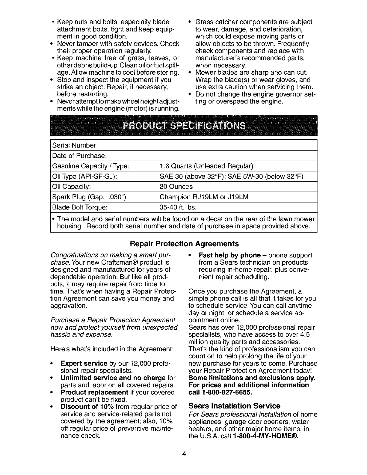
SerialNumber:
Dateof Purchase:
GasolineCapacity/Type: 1.6 Quarts (Unleaded Regular)
Oil Type (API-SF-SJ): SAE 30 (above 32°F); SAE 5W-30 (below 32°F)
Oil Capacity: 20 Ounces
Spark Plug (Gap: .030") Champion RJ19LM or J19LM
Blade Bolt Torque: 35-40 ft. Ibs.
• The model and serial numbers will be found on a decal on the rear of the lawn mower
housing. Record both serial number and date of purchase in space provided above.
Repair Protection Agreements
Congratulations on making a smart pur-
chase. Your new Craftsman® product is
designed and manufactured for years of
dependable operation. But like all prod-
ucts, it may require repair from time to
time. That's when having a Repair Protec-
tion Agreement can save you money and
aggravation.
Purchase a Repair Protection Agreement
now and protect yourself from unexpected
hassle and expense.
Here's what's included in the Agreement:
• Expert service by our 12,000 profe-
sional repair specialists.
• Unlimited service and no charge for
parts and labor on all covered repairs.
• Product replacement if your covered
product can't be fixed.
• Discount of 10% from regular price of
service and service-related parts not
covered by the agreement; also, 10%
off regular price of preventive mainte-
nance check.
Fast help by phone - phone support
from a Sears technician on products
requiring in-home repair, plus conve-
nient repair scheduling.
Once you purchase the Agreement, a
simple phone call is all that it takes for you
to schedule service. You can call anytime
day or night, or schedule a service ap-
pointment online.
Sears has over 12,000 professional repair
specialists, who have access to over 4.5
million quality parts and accessories.
That's the kind of professionalism you can
count on to help prolong the life of your
new purchase for years to come. Purchase
your Repair Protection Agreement today!
Some limitations and exclusions apply.
For prices and additional information
call 1-800-827-6655.
Sears Installation Service
For Sears professional installation of home
appliances, garage door openers, water
heaters, and other major home items, in
the U.S.A. call 1-800-4-MY-HOME®.
4
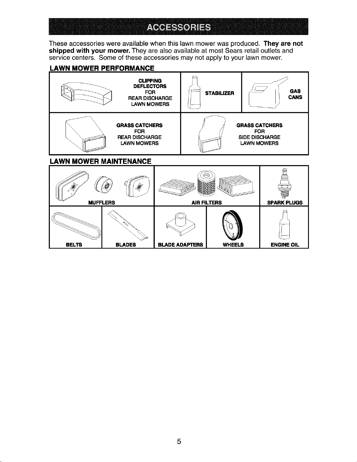
These accessories were available when this lawn mower was produced. They are not
shipped with your mower. They are also available at most Sears retail outlets and
service centers. Some of these accessories may not apply to your lawn mower.
LAWN MOWER PERFORMANCE
CLIPPING
__ DEFLECTORS
FOR STABILIZER
REAR DISCHARGE
LAWN MOWERS
\\\ GRASS CATCHERS GRASS CATCHERS
\\ \ FOR FOR
REAR DISCHARGE SIDE DISCHARGE
LAWN MOWERS LAWN MOWERS
LAWN MOWER MAINTENANCE
MUFFLERS AIR FILTERS SPARK PLUGS
BELTS BLADES BLADE ADAPTERS WHEELS ENGINE OIL
5
Read these instructions and this manual in
its entirety before you attempt to assemble
or operate your new lawn mower.
IMPORTANT: This lawn mower is shipped
WITHOUT OIL OR GASOLINE inthe engine.
Your new lawn mower has been as-
sembled at the factory with the excep-
tion of those parts left unassembled for
shipping purposes. To ensure safe and
proper operation of your lawn mower, all
parts and hardware you assemble must be
tightened securely. Use the correct tools
as necessary to ensure proper tightness.
All parts such as nuts, washers, bolts, etc.,
necessary to complete the assembly have
been placed in the parts bag.
TO REMOVE LAWN MOWER FROM
CARTON
1. Remove loose parts included with
mower.
2. Cut down two end corners of carton
and lay end panel down flat.
3. Remove all packing materials except
padding between upper and lower
handle and padding holding operator
presence control bar to upper handle.
4. Roll lawn mower out of carton and
check carton thoroughly for additional
loose parts.
HOWTO SET UPYOUR LAWN
MOWER
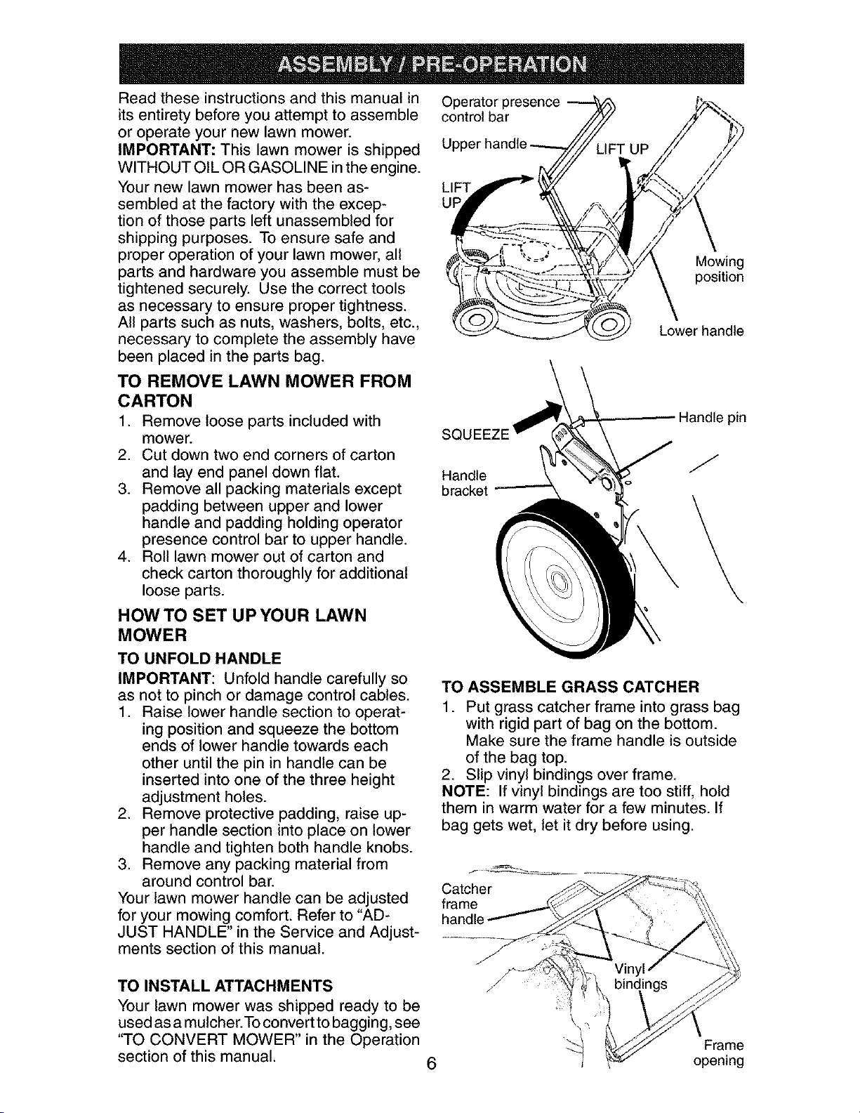
TO UNFOLD HANDLE
IMPORTANT: Unfold handle carefully so
as not to pinch or damage control cables.
1. Raise lower handle section to operat-
ing position and squeeze the bottom
ends of lower handle towards each
other until the pin in handle can be
inserted into one of the three height
adjustment holes.
2. Remove protective padding, raise up-
per handle section into place on lower
handle and tighten both handle knobs.
3. Remove any packing material from
around control bar.
Your lawn mower handle can be adjusted
for your mowing comfort. Refer to "AD-
JUST HANDLE" in the Service and Adjust-
ments section of this manual.
Operator presence
control bar
LIFT
UF
Mowing
position
Lower handle
SQL
Handle
bracket
Handle pin
J
TO ASSEMBLE GRASS CATCHER
1. Put grass catcher frame into grass bag
with rigid part of bag on the bottom.
Make sure the frame handle is outside
of the bag top.
2. Slip vinyl bindings over frame.
NOTE: If vinyl bindings are too stiff, hold
them in warm water for a few minutes. If
bag gets wet, let it dry before using.
Catcher
frame
handle
TO INSTALL ATTACHMENTS
Your lawn mower was shipped ready to be
used as a mulcher.To convert to bagging, see
"TO CONVERT MOWER" in the Operation
section of this manual.
6
Frame
opening
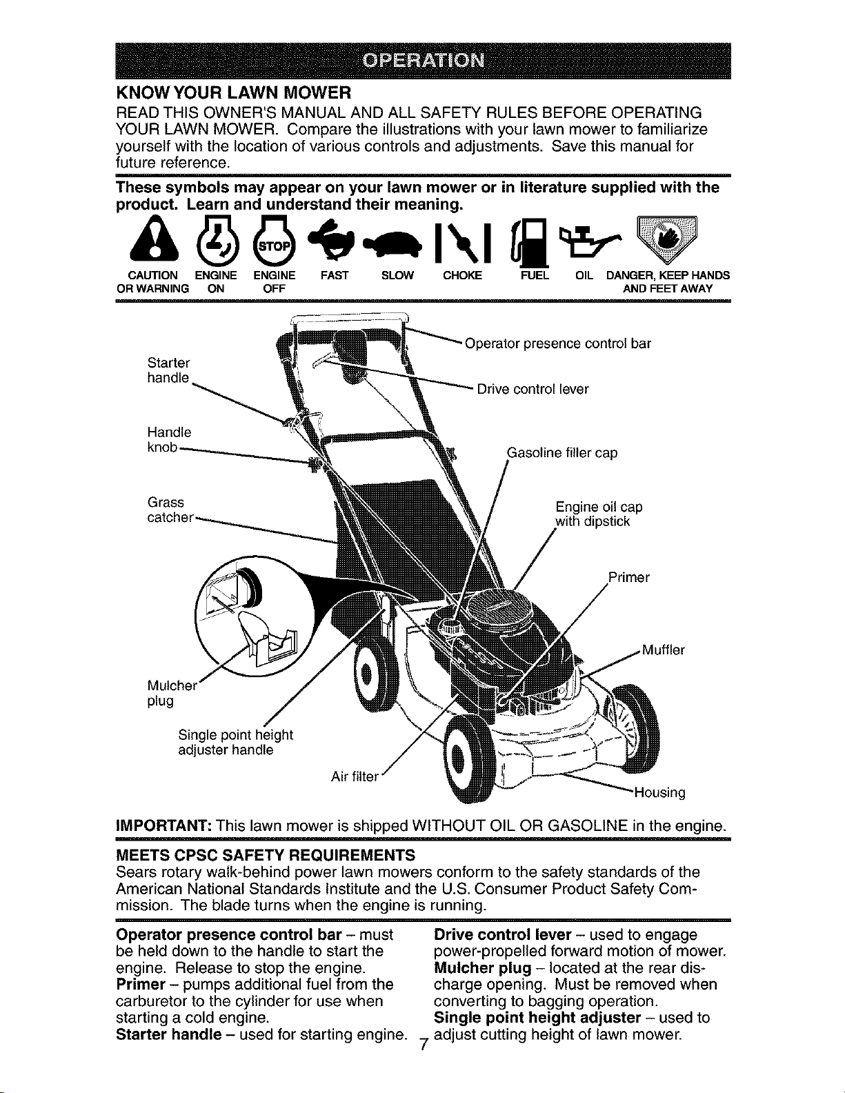
KNOW YOUR LAWN MOWER
READ THIS OWNER'S MANUAL AND ALL SAFETY RULES BEFORE OPERATING
YOUR LAWN MOWER. Compare the illustrations with your lawn mower to familiarize
yourself with the location of various controls and adjustments. Save this manual for
future reference.
These symbols may appear on your lawn mower or in literature supplied with the
product. Learn and understand their meaning.
CAUTION ENGINE ENGINE FAST SLOW CHOKE FUEL OIL DANGER, KEEP HANDS
OR WARNING ON OFF AND FEET AWAY
Starter
handle
Operator presence control bar
Drive control lever
Handle
knol
Gasoline filler cap
Grass
Engine oil cap
with dipstick
Primer
Mulcher
plug
Single point height
adjuster handle
Air filter
Housing
IMPORTANT: This lawn mower is shipped WITHOUT OIL OR GASOLINE in the engine.
MEETS CPSC SAFETY REQUIREMENTS
Sears rotary walk-behind power lawn mowers conform to the safety standards of the
American National Standards Institute and the U.S. Consumer Product Safety Com-
mission. The blade turns when the engine is running.
Operator presence control bar - must
be held down to the handle to start the
engine. Release to stop the engine.
Primer - pumps additional fuel from the
carburetor to the cylinder for use when
starting a cold engine.
Drive control lever - used to engage
power-propelled forward motion of mower.
Mulcher plug - located at the rear dis-
charge opening. Must be removed when
converting to bagging operation.
Single point height adjuster - used to
Starter handle - used for starting engine. 7 adjust cutting height of lawn mower.
Theoperationof any lawn
mowercan resultin foreign
objectsthrownintothe
eyes,whichcan resultin
severeeye damage.Always
wearsafetyglassesor eyeshieldswhile
operatingyourlawnmowerorperforming
any adjustmentsor repairs.We recom-
mendastandardsafetyglassesor wide
visionsafetymaskwornoverspectacles.
HOW TO USE YOUR LAWN MOWER
ENGINE SPEED
The engine speed was set at the factory
for optimum performance. Speed is not
adjustable.
ENGINE ZONE CONTROL
ACAUTION: Federal regulations require
an engine control to be installed on this
lawn mower in order to minimize the
risk of blade contact injury. Do not under
any circumstances attempt to defeat the
function of the operator control. The blade
turns when the engine is running.
• Your lawn mower is equipped with an
operator presence control bar which
requires the operator to be positioned
behind the lawn mower handle to start
and operate the lawn mower.
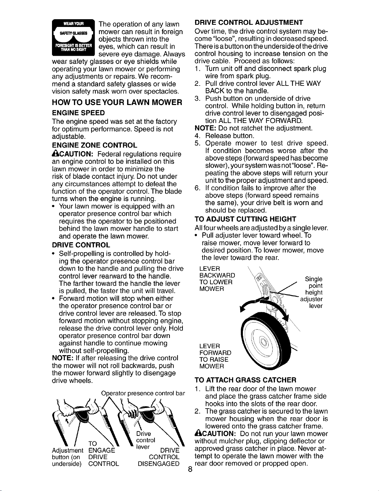
DRIVE CONTROL
• Self-propelling is controlled by hold-
ing the operator presence control bar
down to the handle and pulling the drive
control lever rearward to the handle.
The farther toward the handle the lever
is pulled, the faster the unit will travel.
• Forward motion will stop when either
the operator presence control bar or
drive control lever are released. To stop
forward motion without stopping engine,
release the drive control lever only. Hold
operator presence control bar down
against handle to continue mowing
without self-propelling.
NOTE: If after releasing the drive control
the mower will not roll backwards, push
the mower forward slightly to disengage
drive wheels.
3resence control bar
Drive
control
TO lever
Adjustment ENGAGE DRIVE
button (on DRIVE CONTROL
underside) CONTROL DISENGAGED
8
DRIVE CONTROL ADJUSTMENT
Over time, the drive control system may be-
come "loose", resulting in decreased speed.
There isa button onthe underside ofthe drive
control housing to increase tension on the
drive cable. Proceed as follows:
1. Turn unit off and disconnect spark plug
wire from spark plug.
2. Pull drive control lever ALL THE WAY
BACK to the handle.
3. Push button on underside of drive
control. While holding button in, return
drive control lever to disengaged posi-
tion ALL THE WAY FORWARD.
NOTE: Do not ratchet the adjustment.
4. Release button.
5. Operate mower to test drive speed.
If condition becomes worse after the
above steps (forward speed has become
slower), yoursystem was not "loose". Re-
peating the above steps will return your
unit to the proper adjustment and speed.
6. If condition fails to improve after the
above steps (forward speed remains
the same), your drive belt is worn and
should be replaced.
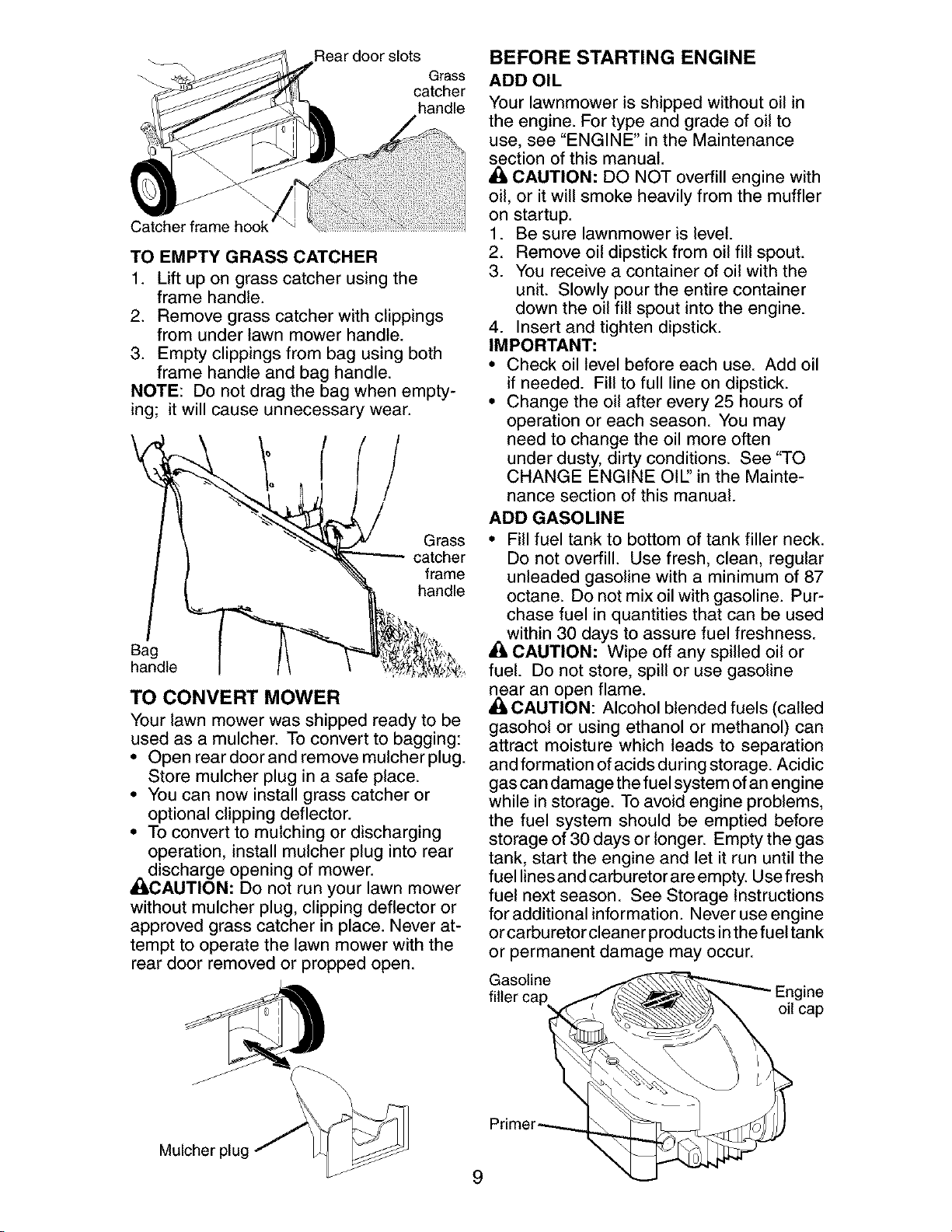
TO ADJUST CUTTING HEIGHT
All four wheels are adjusted by a single lever.
• Pull adjuster lever toward wheel. To
raise mower, move lever forward to
desired position. To lower mower, move
the lever toward the rear.
LEVER
BACKWARD
TO LOWER
MOWER
LEVER
FORWARD
TO RAISE
MOWER
Single
point
height
juster
lever
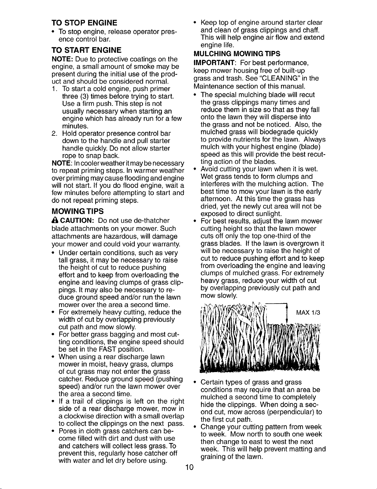
TO ATTACH GRASS CATCHER
1. Lift the rear door of the lawn mower
and place the grass catcher frame side
hooks into the slots of the rear door.
2. The grass catcher is secured to the lawn
mower housing when the rear door is
lowered onto the grass catcher frame.
ACAUTION: Do not run your lawn mower
without mulcher plug, clipping deflector or
approved grass catcher in place. Never at-
tempt to operate the lawn mower with the
rear door removed or propped open.
Rear door slots
Grass
catcher
handle
Catcher frame ho
TO EMPTY GRASS CATCHER
1. Lift up on grass catcher using the
frame handle.
2. Remove grass catcher with clippings
from under lawn mower handle.
3. Empty clippings from bag using both
frame handle and bag handle.
NOTE: Do not drag the bag when empty-
ing; it will cause unnecessary wear.
Grass
catcher
frame
handle
Bag
handle
TO CONVERT MOWER
Your lawn mower was shipped ready to be
used as a mulcher. To convert to bagging:
• Open reardoorand remove mulcherplug.
Store mulcher plug in a safe place.
• You can now install grass catcher or
optional clipping deflector.
• To convert to mulching or discharging
operation, install mulcher plug into rear
_idischarge opening of mower.
CAUTION: Do not run your lawn mower
without mulcher plug, clipping deflector or
approved grass catcher in place. Never at-
tempt to operate the lawn mower with the
rear door removed or propped open.
BEFORE STARTING ENGINE
ADD OIL
Your lawnmower is shipped without oil in
the engine. For type and grade of oil to
use, see "ENGINE" in the Maintenance
section of this manual.
CAUTION: DO NOT overfill engine with
oil, or it will smoke heavily from the muffler
on startup.
1. Be sure lawnmower is level.
2. Remove oil dipstick from oil fill spout.
3. You receive a container of oil with the
unit. Slowly pour the entire container
down the oil fill spout into the engine.
4. Insert and tighten dipstick.
IMPORTANT:
• Check oil level before each use. Add oil
if needed. Fill to full line on dipstick.
• Change the oil after every 25 hours of
operation or each season. You may
need to change the oil more often
under dusty, dirty conditions. See "TO
CHANGE ENGINE OIE' in the Mainte-
nance section of this manual.
ADD GASOLINE
• Fill fuel tank to bottom of tank filler neck.
Do not overfill. Use fresh, clean, regular
unleaded gasoline with a minimum of 87
octane. Do not mix oil with gasoline. Pur-
chase fuel in quantities that can be used
within 30 days to assure fuel freshness.
• 1=CAUTION: Wipe off any spilled oil or
fuel. Do not store, spill or use gasoline
near
. an open flame.
CAUTION: Alcohol blended fuels (called
gasohol or using ethanol or methanol) can
attract moisture which leads to separation
and formation of acids during storage. Acidic
gas can damage the fuel system of an engine
while in storage. To avoid engine problems,
the fuel system should be emptied before
storage of 30 days or longer. Empty the gas
tank, start the engine and let it run until the
fuel lines and carburetor are empty. Use fresh
fuel next season. See Storage Instructions
for additional information. Never use engine
orcarburetor cleaner products in the fuel tank
or permanent damage may occur.
Gasoline
Engine
oil cap
f
Mulcher plu£
9
TO STOP ENGINE
• To stop engine, release operator pres-
ence control bar.
TO START ENGINE
NOTE: Due to protective coatings on the
engine, a small amount of smoke may be
present during the initial use of the prod-
uct and should be considered normal.
1. To start a cold engine, push primer
three (3) times before trying to start.
Use a firm push. This step is not
usually necessary when starting an
engine which has already run for a few
minutes.
2. Hold operator presence control bar
down to the handle and pull starter
handle quickly. Do not allow starter
rope to snap back.
NOTE: In cooler weather itmay be necessary
to repeat priming steps. In warmer weather
over priming may cause flooding and engine
will not start. If you do flood engine, wait a
few minutes before attempting to start and
do not repeat priming steps.
MOWING TIPS
CAUTION: Do not use de-thatcher
blade attachments on your mower. Such
attachments are hazardous, will damage
your mower and could void your warranty.
• Under certain conditions, such as very
tall grass, it may be necessary to raise
the height of cut to reduce pushing
effort and to keep from overloading the
engine and leaving clumps of grass clip-
pings. It may also be necessary to re-
duce ground speed and/or run the lawn
mower over the area a second time.
• For extremely heavy cutting, reduce the
width of cut by overlapping previously
cut path and mow slowly.
• For better grass bagging and most cut-
ting conditions, the engine speed should
be set in the FAST position.
• When using a rear discharge lawn
mower in moist, heavy grass, clumps
of cut grass may not enter the grass
catcher. Reduce ground speed (pushing
speed) and/or run the lawn mower over
the area a second time.
• If a trail of clippings is left on the right
side of a rear discharge mower, mow in
a clockwise direction with a small overlap
to collect the clippings on the next pass.
• Pores in cloth grass catchers can be-
come filled with dirt and dust with use
and catchers will collect less grass. To
prevent this, regularly hose catcher off
with water and let dry before using.
10
• Keep top of engine around starter clear
and clean of grass clippings and chaff.
This will help engine air flow and extend
engine life.
MULCHING MOWING TIPS
IMPORTANT: For best performance,
keep mower housing free of built-up
grass and trash. See "CLEANING" in the
Maintenance section of this manual.
• The special mulching blade will recut
the grass clippings many times and
reduce them in size so that as they fall
onto the lawn they will disperse into
the grass and not be noticed. Also, the
mulched grass will biodegrade quickly
to provide nutrients for the lawn. Always
mulch with your highest engine (blade)
speed as this will provide the best recut-
ting action of the blades.
• Avoid cutting your lawn when it is wet.
Wet grass tends to form clumps and
interferes with the mulching action. The
best time to mow your lawn is the early
afternoon. At this time the grass has
dried, yet the newly cut area will not be
exposed to direct sunlight.
• For best results, adjust the lawn mower
cutting height so that the lawn mower
cuts off only the top one-third of the
grass blades. If the lawn is overgrown it
will be necessary to raise the height of
cut to reduce pushing effort and to keep
from overloading the engine and leaving
clumps of mulched grass. For extremely
heavy grass, reduce your width of cut
by overlapping previously cut path and
mow slowly.
MAXI_
• Certain types of grass and grass
conditions may require that an area be
mulched a second time to completely
hide the clippings. When doing a sec-
ond cut, mow across (perpendicular) to
the first cut path.
• Change your cutting pattern from week
to week. Mow north to south one week
then change to east to west the next
week. This will help prevent matting and
graining of the lawn.
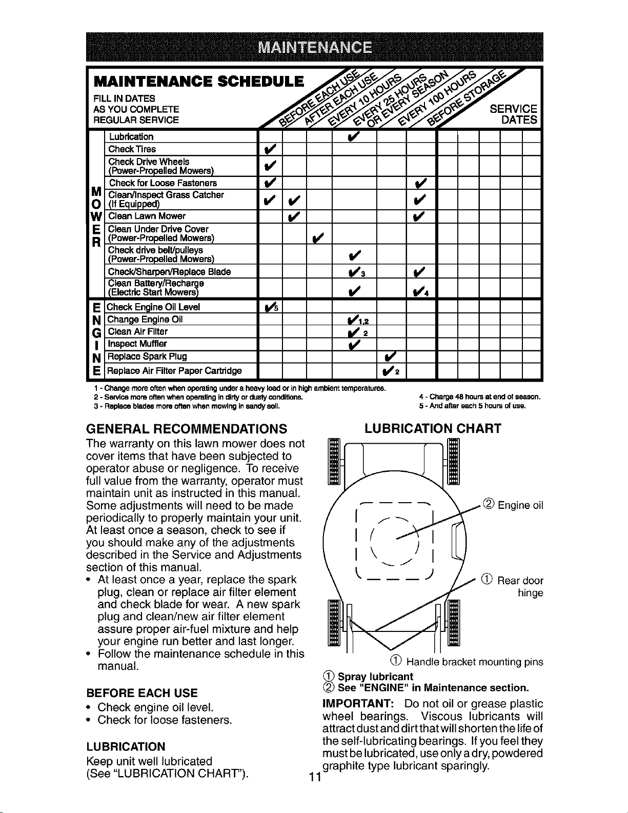
MAINTENANCE SCHEDULE /_:;,_°_o_y
AS YOU COMPLETE S
REGO RSERV,CE
Lubrication It#'
CheckTires tf'
CheckDriveWheels
(Power-Propelled Mowers) I_
Check for Loose Fasteners t_' Ikf
Clean/Inspect Grass Catcher
(If Equipped) _
W Clean Lawn Mower _
RE Clean Under Drive Cover(Power-Propelled Mowers)
Check drive belt/pulleys
(Power-Propelled Mowers)
Check/Sharpen/Replace Blade
Clean Battery/Recharge
IElectdc Start MowersI
E Check Engine Oil Level
Change Engine Oil
G Clean Air Filter
Inspect Muffler
N Replace Spark Plug
Replace Air Filter Paper Cartridge
V'=
1- Changemoreoftenwhenopem6ngundera heavyloadorinhigh ambienttemperatures.
2 - Servicemoraoftenwhen operatingindirtyordustyconditions,
3 - Replacebladesmoreoftenwhen mowinginsandysoil,
4 - Charge48 hoursatend ofseason.
5 - Andaftereach5 hoursof use.
GENERAL RECOMMENDATIONS
The warranty on this lawn mower does not
cover items that have been subjected to
operator abuse or negligence. To receive
full value from the warranty, operator must
maintain unit as instructed in this manual.
Some adjustments will need to be made
periodically to properly maintain your unit.
At least once a season, check to see if
you should make any of the adjustments
described in the Service and Adjustments
section of this manual.
• At least once a year, replace the spark
plug, clean or replace air filter element
and check blade for wear. A new spark
plug and clean/new air filter element
assure proper air-fuel mixture and help
your engine run better and last longer.
• Follow the maintenance schedule in this
manual.
BEFORE EACH USE
• Check engine oil level.
• Check for loose fasteners.
LUBRICATION
Keep unit well lubricated
(See "LUBRICATION CHART").
LUBRICATION CHART
;ne oil
(_) Rear door
hinge
(_) Handle bracket mounting pins
_ Spray lubricant
See "ENGINE" in Maintenance section.
IMPORTANT: Do not oil or grease plastic
wheel bearings. Viscous lubricants will
attract dust and dirtthatwill shorten the life of
the self-lubricating bearings. If you feel they
must be lubricated, use only a dry, powdered
11graphite type lubricant sparingly.
LAWN MOWER
Always observe safety rules when per-
forming any maintenance.
TIRES
• Keep tires free of gasoline, oil, or insect
control chemicals which can harm rub-
ber.
• Avoid stumps, stones, deep ruts, sharp
objects and other hazards that may
cause tire damage.
DRIVE WHEELS
Check rear drive wheels each time you
mow to be sure they move freely. The
wheels not turning freely means trash,
grass cuttings, etc., may be inside the
drive wheel and dust cover area and must
be cleaned out to free drive wheels.
If necessary to clean the drive wheels,
check both rear wheels.
BLADE CARE
For best results, mower blade must be
kept sharp. Replace a bent or damaged
blade.
TO REMOVE BLADE
1. Disconnect spark plug wire from spark
plug and place wire where it cannot
come in contact with spark plug.
2. Turn lawn mower on its side. Make
sure air filter and carburetor are up.
3. Use a wood block between blade and
mower housing to prevent blade from
turning when removing blade bolt.
NOTE: Protect your hands with gloves
and/or wrap blade with heavy cloth.
4. Remove blade bolt by turning counter-
clockwise.
5. Remove blade and attaching hard-
ware (bolt, lock washer and hardened
washer).
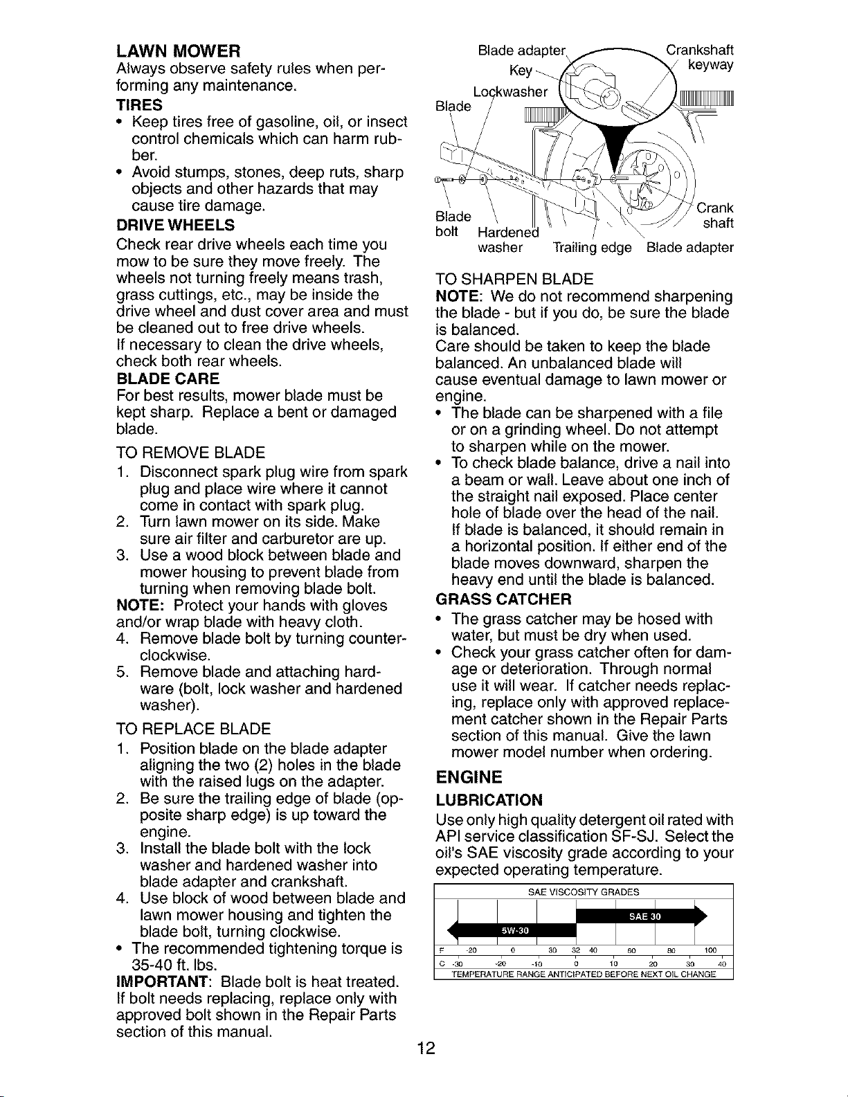
TO REPLACE BLADE
1. Position blade on the blade adapter
aligning the two (2) holes in the blade
with the raised lugs on the adapter.
2. Be sure the trailing edge of blade (op-
posite sharp edge) is up toward the
engine.
3. Install the blade bolt with the lock
washer and hardened washer into
blade adapter and crankshaft.
4. Use block of wood between blade and
lawn mower housing and tighten the
blade bolt, turning clockwise.
• The recommended tightening torque is
35-40 ft. Ibs.
IMPORTANT: Blade bolt is heat treated.
If bolt needs replacing, replace only with
approved bolt shown in the Repair Parts
section of this manual.
Blade adapter Crankshaft
Key _ keyway
Blade
Blade shaft
bolt / \
washer Trailing edge Blade adapter
TO SHARPEN BLADE
NOTE: We do not recommend sharpening
the blade - but if you do, be sure the blade
is balanced.
Care should be taken to keep the blade
balanced. An unbalanced blade will
cause eventual damage to lawn mower or
engine.
• The blade can be sharpened with a file
or on a grinding wheel. Do not attempt
to sharpen while on the mower.
• To check blade balance, drive a nail into
a beam or wall. Leave about one inch of
the straight nail exposed. Place center
hole of blade over the head of the nail.
If blade is balanced, it should remain in
a horizontal position. If either end of the
blade moves downward, sharpen the
heavy end until the blade is balanced.
GRASS CATCHER
The grass catcher may be hosed with
water, but must be dry when used.
Check your grass catcher often for dam-
age or deterioration. Through normal
use it will wear. If catcher needs replac-
ing, replace only with approved replace-
ment catcher shown in the Repair Parts
section of this manual. Give the lawn
mower model number when ordering.
ENGINE
LUBRICATION
Use only high quality detergent oil rated with
API service classification SF-SJ. Select the
oil's SAE viscosity grade according to your
expected operating temperature.
SAE VISCOSITY GRADES
F
c ._ -2o .I; ; 17 io 3o 4;
TEMPERATURE RANGE ANTICIPATED BEFORE NEXT OIL CHANGE
12
NOTE: Although multi-viscosity oils
(5W30, 10W30 etc.) improve starting in
cold weather, these multi-viscosity oils will
result in increased oil consumption when
used above 32°E Check your engine oil
level more frequently to avoid possible
engine damage from running low on oil.
Change the oil after every 25 hours of opera-
tion orat least once a year if the lawn mower
is not used for 25 hours in one year.
Check the crankcase oil level before
starting the engine and after each five (5)
hours of continuous use. Tighten oil plug
securely each time you check the oil level.
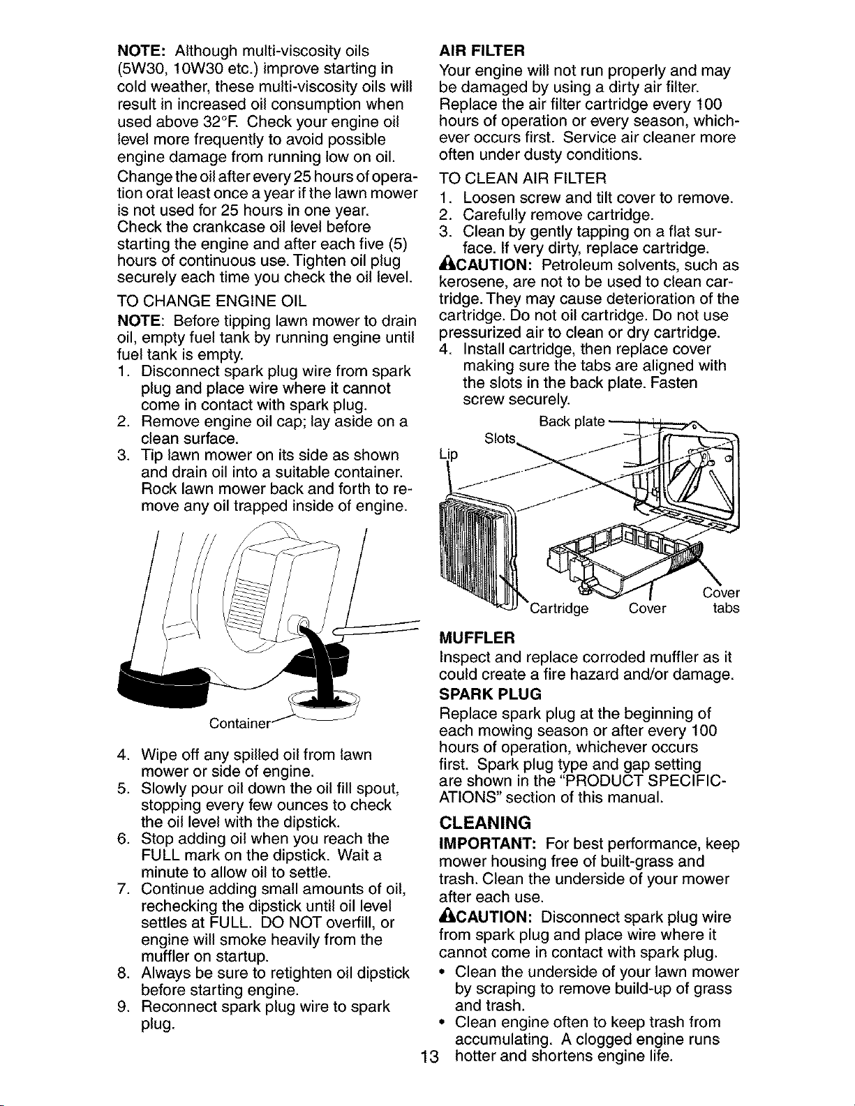
TO CHANGE ENGINE OIL
NOTE: Before tipping lawn mower to drain
oil, empty fuel tank by running engine until
fuel tank is empty.
1. Disconnect spark plug wire from spark
plug and place wire where it cannot
come in contact with spark plug.
2. Remove engine oil cap; lay aside on a
clean surface.
3. Tip lawn mower on its side as shown
and drain oil into a suitable container.
Rock lawn mower back and forth to re-
move any oil trapped inside of engine.
4. Wipe off any spilled oil from lawn
mower or side of engine.
5. Slowly pour oil down the oil fill spout,
stopping every few ounces to check
the oil level with the dipstick.
6. Stop adding oil when you reach the
FULL mark on the dipstick. Wait a
minute to allow oil to settle.
7. Continue adding small amounts of oil,
rechecking the dipstick until oil level
settles at FULL. DO NOT overfill, or
engine will smoke heavily from the
muffler on startup.
8. Always be sure to retighten oil dipstick
before starting engine.
9. Reconnect spark plug wire to spark
plug.
AIR FILTER
Your engine will not run properly and may
be damaged by using a dirty air filter.
Replace the air filter cartridge every 100
hours of operation or every season, which-
ever occurs first. Service air cleaner more
often under dusty conditions.
TO CLEAN AIR FILTER
1. Loosen screw and tilt cover to remove.
2. Carefully remove cartridge.
3. Clean by gently tapping on a flat sur-
_i face. If very dirty, replace cartridge.
CAUTION: Petroleum solvents, such as
kerosene, are not to be used to clean car-
tridge. They may cause deterioration of the
cartridge. Do not oil cartridge. Do not use
pressurized air to clean or dry cartridge.
4. Install cartridge, then replace cover
making sure the tabs are aligned with
the slots in the back plate. Fasten
screw securely.
Back
Slots
Cover
Cover tabs
MUFFLER
Inspect and replace corroded muffler as it
could create a fire hazard and/or damage.
SPARK PLUG
Replace spark plug at the beginning of
each mowing season or after every 100
hours of operation, whichever occurs
first. Spark plug type and gap setting
are shown in the "PRODUCT SPECIFIC-
ATIONS" section of this manual.
CLEANING
IMPORTANT: For best performance, keep
mower housing free of built-grass and
trash. Clean the underside of your mower
after each use.
•II,CAUTION: Disconnect spark plug wire
from spark plug and place wire where it
cannot come in contact with spark plug.
• Clean the underside of your lawn mower
by scraping to remove build-up of grass
and trash.
• Clean engine often to keep trash from
accumulating. A clogged engine runs
13 hotter and shortens engine life.
• Keep finished surfaces and wheels free
of all gasoline, oil, etc.
• We do not recommend using a garden
hose to clean lawn mower unless the
electrical system, muffler, air filter and
carburetor are covered to keep water
out. Water in engine can result in short-
ened engine life.
CLEAN UNDER DRIVE COVER
Clean under drive cover at least twice a
season. Scrape underside of cover with
putty knife or similar tool to remove any
build-up of trash or grass on underside of
drive cover.
AI::_WARNING: To avoid serious injury,
before performing any service and
adjustments:
1. Release control bar and stop engine.
2. Make sure the blade and all moving
parts have completely stopped.
3. Disconnect spark plug wire from spark
plug and place wire where it cannot
come in contact with spark plug.
LAWN MOWER
TO ADJUST CUTTING HEIGHT
See "TO ADJUST CUTTING HEIGHT" in
the Operation section of this manual.
REAR DEFLECTOR
The rear deflector, attached between the rear
wheels of your mower, is provided to minimize
the possibility that objects will be thrown out
of the rear of the mower into the operator
mowing position. If the deflector becomes
damaged, it should be replaced.
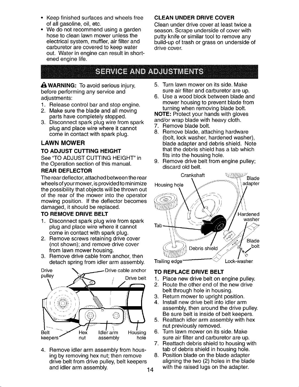
TO REMOVE DRIVE BELT
1. Disconnect spark plug wire from spark
plug and place wire where it cannot
come in contact with spark plug.
2. Remove screws retaining drive cover
(not shown); and remove drive cover
from lawn mower housing.
3. Remove drive cable from anchor, then
detach spring from idler arm assembly.
5. Turn lawn mower on its side. Make
sure air filter and carburetor are up.
6. Use a wood block between blade and
mower housing to prevent blade from
turning when removing blade bolt.
NOTE: Protect your hands with gloves
and/or wrap blade with heavy cloth.
7. Remove blade bolt.
8. Remove blade, attaching hardware
(bolt, lock washer, hardened washer),
blade adapter and debris shield. Note
that the debris shield has a tab which
fits into the housing hole.
9. Remove drive belt from engine pulley;
discard old belt.
Crankshaft
Housing hole
Tab-
Hardened
washer
3lade
bolt
Trailing edge
Drive anchor
pulley Drive belt
Belt
4_
r arm Housing
nut assembly hole
Remove idler arm assembly from hous-
ing by removing hex nut; then remove
drive belt from drive pulley, belt keepers
and idler arm assembly. 14
TO REPLACE DRIVE BELT
f. Place new drive belt on engine pulley.
2. Route the other end of the new drive
belt through hole in housing.
3. Return mower to upright position.
4. Install new drive belt into idler arm
assembly, then around the drive pulley.
Be sure belt is inside of belt keepers.
5. Reattach idler arm assembly with hex
nut previously removed.
6. Turn lawn mower on its side. Make
sure air filter and carburetor are up.
7. Reattach debris shield to housing with
tab of debris shield in housing hole.
8. Position blade on the blade adapter
aligning the two (2) holes in the blade
with the raised lugs on the adapter.
9. Besurethetrailingedgeof blade(op-
positesharpedge) isup towardthe
engineas shown.
10.Installthe bladebolt withthe lock
washerand hardenedwasherinto
bladeadapterandcrankshaft.
11.Useblockof woodbetweenbladeand
lawnmowerhousingandtightenthe
bladebolt,turningclockwise.
° Therecommendedtighteningtorqueis
35-40ft. Ibs.
IMPORTANT:Bladebolt is heattreated.
Ifbolt needsreplacing,replaceonlywith
approvedboltshownin the RepairParts
sectionofthismanual.
12.Returnmowerto uprightposition.
13.Reattachdrivecablespringto the idler
armassembly,then reattachdrive
cableto anchor.
14.Reattachdrivecoverwithscrewsprevi-
ouslyremoved.
15.Connectspark plugwireto sparkplug.
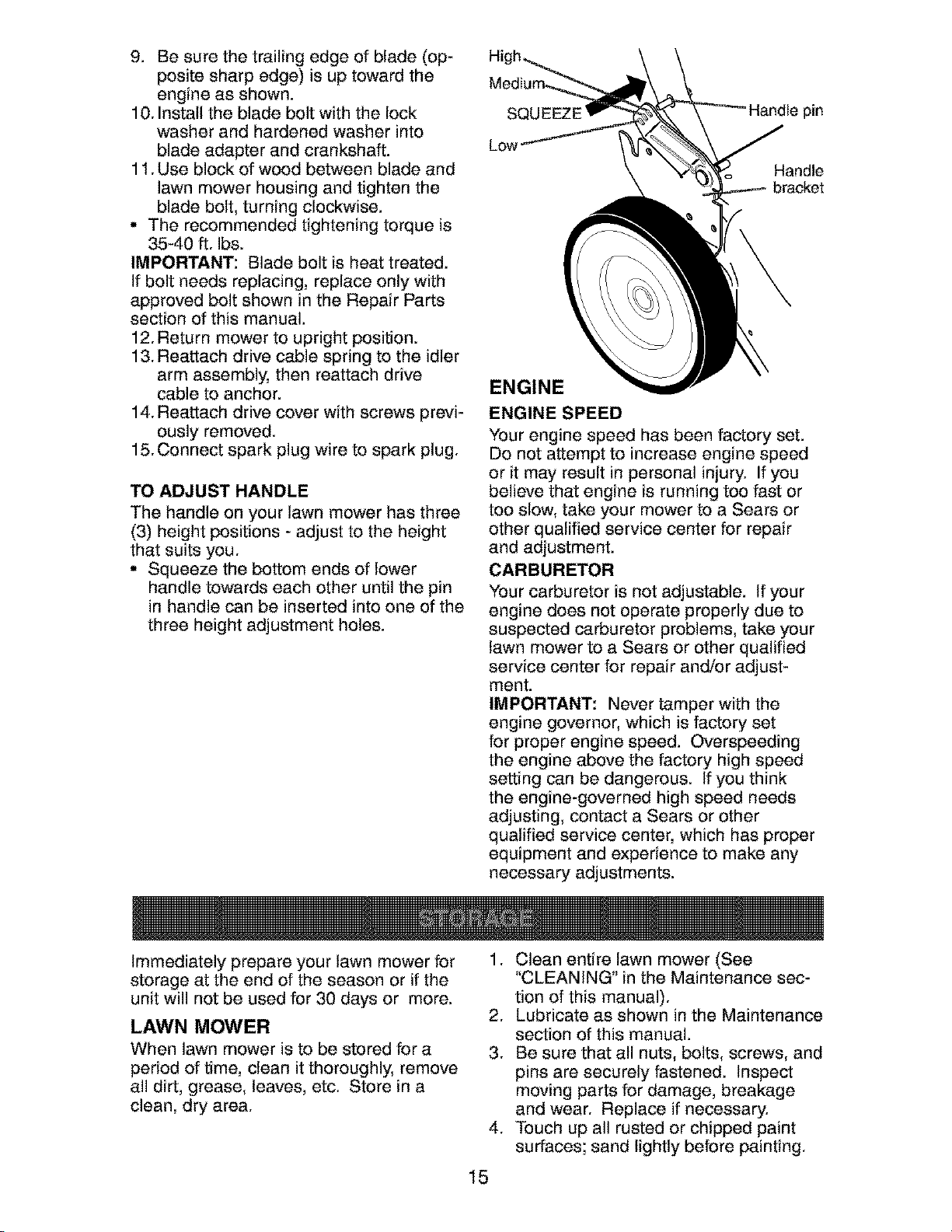
TOADJUST HANDLE
The handle on your lawn mower has three
(3) height positions - adjust to the height
that suits you.
• Squeeze the bottom ends of lower
handle towards each other until the pin
in handle can be inserted into one of the
three height adjustment holes.
SQL pin
Low
Handle
bracket
ENGINE
ENGINE SPEED
Your engine speed has been factory set.
Do not attempt to increase engine speed
or it may result in personal injury. If you
believe that engine is running too fast or
too slow, take your mower to a Sears or
other qualified service center for repair
and adjustment.
CARBURETOR
Your carburetor is not adjustable. If your
engine does not operate properly due to
suspected carburetor problems, take your
lawn mower to a Sears or other qualified
service center for repair and/or adjust-
ment.
IMPORTANT: Never tamper with the
engine governor, which is factory set
for proper engine speed. Overspeeding
the engine above the factory high speed
setting can be dangerous. If you think
the engine-governed high speed needs
adjusting, contact a Sears or other
qualified service center, which has proper
equipment and experience to make any
necessary adjustments.
Immediately prepare your lawn mower for
storage at the end of the season or if the
unit will not be used for 30 days or more.
LAWN MOWER
When lawn mower is to be stored for a
period of time, clean it thoroughly, remove
all dirt, grease, leaves, etc. Store in a
clean, dry area.
,
15
1. Clean entire lawn mower (See
"CLEANING" in the Maintenance sec-
tion of this manual).
2. Lubricate as shown in the Maintenance
section of this manual.
3. Be sure that all nuts, bolts, screws, and
pins are securely fastened. Inspect
moving parts for damage, breakage
and wear. Replace if necessary.
Touch up all rusted or chipped paint
surfaces; sand lightly before painting.
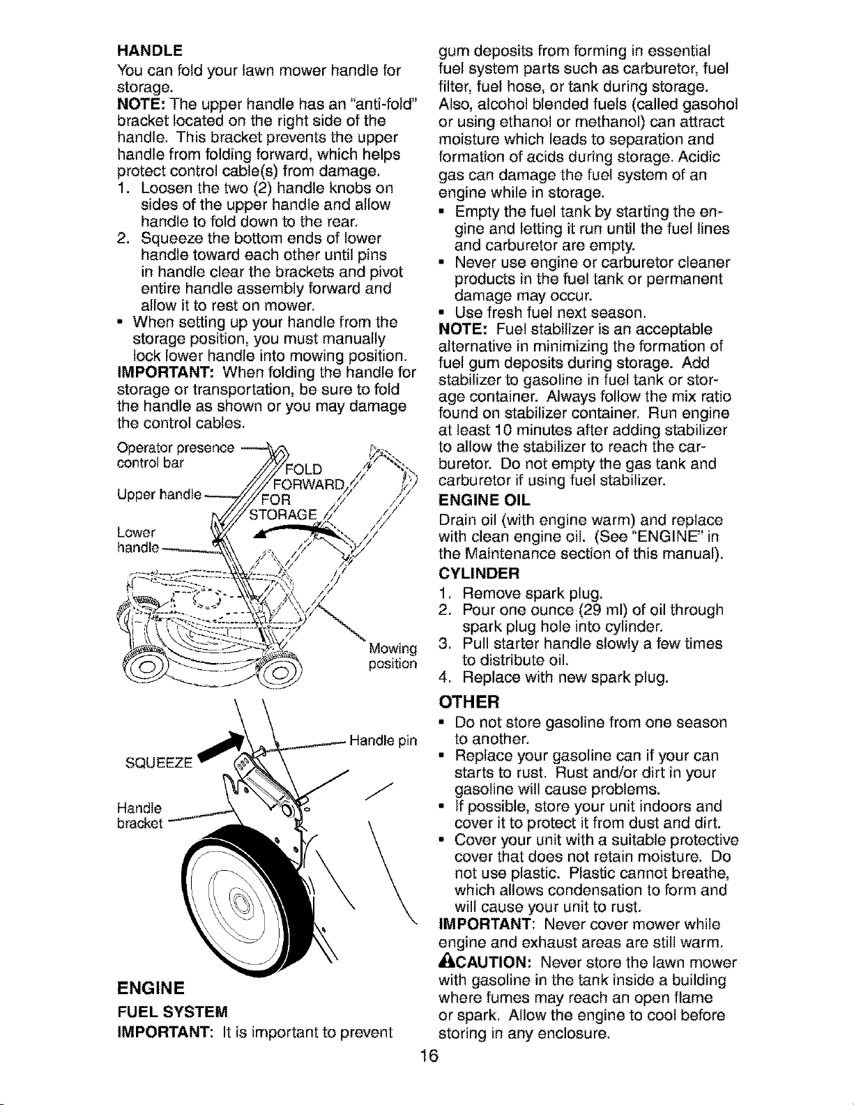
HANDLE
You can fold your lawn mower handle for
storage.
NOTE: The upper handle has an "anti-fold"
bracket located on the right side of the
handle. This bracket prevents the upper
handle from folding forward, which helps
protect control cable(s) from damage.
1. Loosen the two (2) handle knobs on
sides of the upper handle and allow
handle to fold down to the rear.
2. Squeeze the bottom ends of lower
handle toward each other until pins
in handle clear the brackets and pivot
entire handle assembly forward and
allow it to rest on mower.
• When setting up your handle from the
storage position, you must manually
lock lower handle into mowing position.
IMPORTANT: When folding the handle for
storage or transportation, be sure to fold
the handle as shown or you may damage
the control cables.
Operator presence
control bar
Lower
Mowing
position
SQUEEZE
Handle
b_c_t
Handle pin
/
ENGINE
FUEL SYSTEM
IMPORTANT: It is important to prevent
gum deposits from forming in essential
fuel system parts such as carburetor, fuel
filter, fuel hose, or tank during storage.
Also, alcohol blended fuels (called gasohol
or using ethanol or methanol) can attract
moisture which leads to separation and
formation of acids during storage. Acidic
gas can damage the fuel system of an
engine while in storage.
° Empty the fuel tank by starting the en-
gine and letting it run until the fuel lines
and carburetor are empty.
° Never use engine or carburetor cleaner
products in the fuel tank or permanent
damage may occur.
° Use fresh fuel next season.
NOTE: Fuel stabilizer is an acceptable
alternative in minimizing the formation of
fuel gum deposits during storage. Add
stabilizer to gasoline in fuel tank or stor-
age container. Always follow the mix ratio
found on stabilizer container. Run engine
at least 10 minutes after adding stabilizer
to allow the stabilizer to reach the car-
buretor. Do not empty the gas tank and
carburetor if using fuel stabilizer.
ENGINE OIL
Drain oil (with engine warm) and replace
with clean engine oil. (See "ENGINE" in
the Maintenance section of this manual).
CYLINDER
1. Remove spark plug.
2. Pour one ounce (29 ml) of oil through
spark plug hole into cylinder.
3. Pull starter handle slowly a few times
to distribute oil.
4. Replace with new spark plug.
OTHER
• Do not store gasoline from one season
to another.
° Replace your gasoline can if your can
starts to rust. Rust and/or dirt in your
gasoline will cause problems.
° If possible, store your unit indoors and
cover it to protect it from dust and dirt.
° Cover your unit with a suitable protective
cover that does not retain moisture. Do
not use plastic. Plastic cannot breathe,
which allows condensation to form and
will cause your unit to rust.
IMPORTANT: Never cover mower while
engine and exhaust areas are still warm.
• I,CAUTION: Never store the lawn mower
with gasoline in the tank inside a building
where fumes may reach an open flame
or spark. Allow the engine to cool before
storing in any enclosure.
16
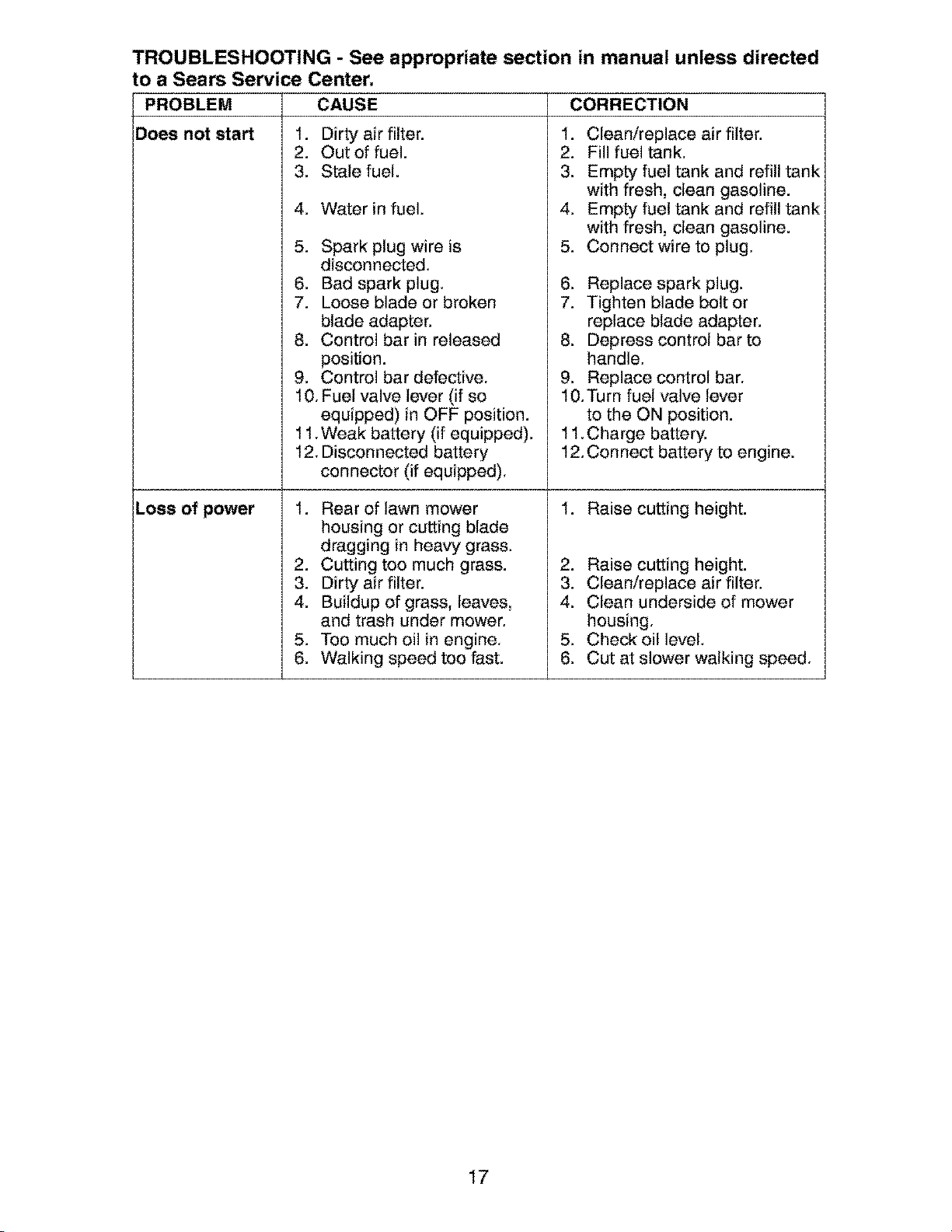
TROUBLESHOOTING - See appropriate section in manual unless directed
to a Sears Service Center.
PROBLEM CAUSE CORRECTION
Does not start
Loss of power
1. Dirty air filter.
2. Out of fuel.
3. Stale fuel.
4. Water in fuel.
5. Spark plug wire is
disconnected.
6. Bad spark plug.
7. Loose blade or broken
blade adapter.
8. Control bar in released
position.
9. Control bar defective,
.
2.
3.
4.
5.
6.
7.
8.
9.
Clean/replace air filter.
Fill fuel tank,
Empty fuel tank and refill tank
with fresh, clean gasoline.
Empty fuel tank and refill tank
with fresh, clean gasoline.
Connect wire to plug,
Replace spark plug.
Tighten blade bolt or
replace blade adapter.
Depress control bar to
handle,
Replace control bar,
10, Fuel valve lever (if so
equipped) in OFF position.
11,Weak battery (if equipped).
12. Disconnected battery
connector (if equipped),
1. Rear of lawn mower
housing or cutting blade
dragging in heavy grass.
2. Cutting too much grass.
3. Dirty air filter.
4. Buildup of grass, leaves,
and trash under mower.
5. Too much oil in engine.
6. Walking speed too fast.
10,Turn fuel valve lever
to the ON position.
11,Charge battery.
12,Connect battery to engine.
1. Raise cutting height.
2. Raise cutting height.
3. Clean/replace air filter.
4. Clean underside of mower
housing.
5. Check oil level.
6. Cut at slower walking speed.
17
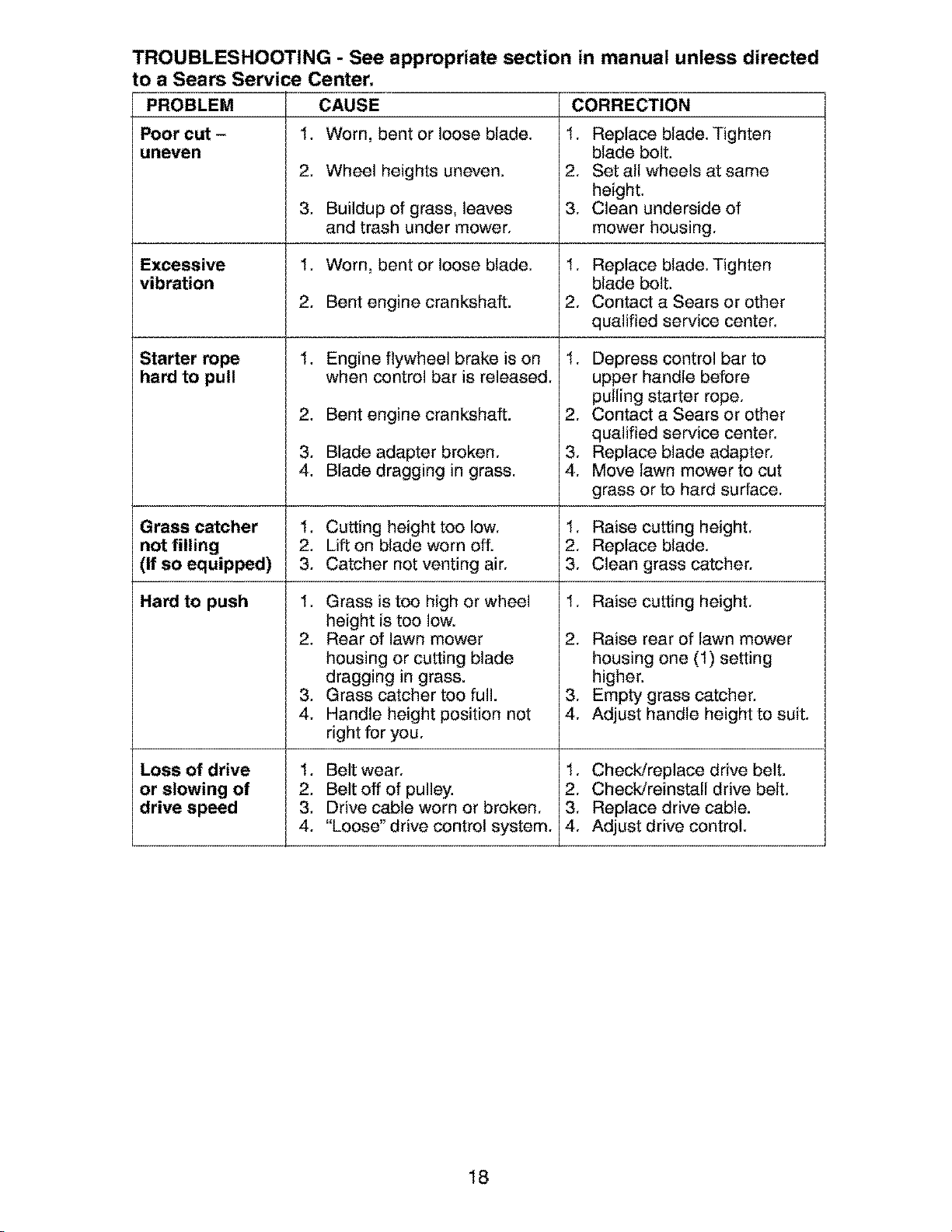
TROUBLESHOOTING - See appropriate section in manual unless directed
to a Sears Service Center.
CAUSE CORRECTIONPROBLEM
Poor cut -
uneven
Excessive
vibration
Starter rope
hard to pull
Grass catcher
not filling
(If so equipped)
Hard to push
Loss of drive
or slowing of
drive speed
1. Worn, bent or loose blade.
2. Wheel heights uneven.
3. Buildup of grass, leaves
and trash under mower.
1. Worn, bent or loose blade.
2. Bent engine crankshaft.
.
2.
3.
4.
Engine flywheel brake is on
when control bar is released.
Bent engine crankshaft.
Blade adapter broken.
Blade dragging in grass.
1. Cutting height too low.
2. Lift on blade worn off.
3, Catcher not venting air,
1. Grass is too high or wheel
height is too low.
2. Rear of lawn mower
housing or cutting blade
dragging in grass.
3, Grass catcher too full.
4. Handle height position not
right for you,
1. Belt wear.
2, Belt off of pulley.
3, Drive cable worn or broken,
4, "Loose" drive control system,
1. Replace blade. Tighten
blade bolt.
2. Set all wheels at same
height.
3. Clean underside of
mower housing.
1. Replace blade. Tighten
blade bolt.
2. Contact a Sears or other
qualified service center.
1. Depress control bar to
upper handle before
pulling starter rope.
2. Contact a Sears or other
qualified service center.
3. Replace blade adapter.
4. Move lawn mower to cut
grass or to hard surface.
1. Raise cutting height.
2. Replace blade.
3. Clean grass catcher.
1. Raise cutting height.
2. Raise rear of lawn mower
housing one (1) setting
higher.
3. Empty grass catcher.
4. Adjust handle height to suit.
1. Check/replace drive belt.
2. Check/reinstall drive belt.
3. Replace drive cable.
4. Adjust drive control.
18
Garantia ......................................................... 19
Reglas de Seguridad ................................ 19-21
Especificaciones del Producto ....................... 21
Montaje / Pre-Operaci6n ............................... 22
Operaci6n ................................................. 24-27
Mantenimiento .......................................... 28-30
Programa de Mantenimiento ......................... 28
Servicio y Adjustes ................................... 31-32
Almaeenamiento ....................................... 32-33
Identificaci6n de problemas ...................... 33-34
Partes de repuesto .................................. 3543
Servicio Sears .................................. Contratapa
GARANT[A LIMITADA DE DOS A_IOS PARA LA SEGADORA A MOTOR CRAFTSMAN
For dos (2) aSos, a partir de la fecha de compra, cuando esta Segadora Craftsman se mantenga,
lubrique y afine seg_n las instrucciones para la operaci6n y el mantenimiento en el manual del
dueSo, Sears repararA gratis todo defecto en el material y la mano de obra.
Si la Segadora Craftsman se usa para fines comerciales o de arriendo, esta garantia s6!o se aplica
pot noventa (90) d_as a partir de la fecha de compra.
Esta Garantia no cubre:
o Artlculos que se desgastan durante el uso normal tales como las cuchillas segadoras rotatorias,
los adaptadores de Ia cuchilla, las corneas, los filtros de aire y las bujias.
o Reparaciones necesarias debido al abuso o a la negligeneia del operador, incluy_ndose a los
cig_eSales doblados y a la falta de mantenimiento del equipo seg_n Ias instrucciones que se
incluyen en el manual del dueSo.
El servicio de garantia esta disponible aI devolver Ia segadora a motor Craftsman al Centro de
Servicio Sears mas eereano en los Estados Unidos. Esta garantia se aplica solamente mientras el
producto este en uso en los Estados Unidos.
Esta Garantia le otorga derechos legales especfficos, y puede que tambi_n tenga otros derechos
que varian de estado a estado.
Sears, Roebuck and Co,, D/817WA, Hoffman Estates, IL 60179 USA
IMPORTANTE: Esta maquina cortadaora es eapaz de amputar las manos y los manos y los pies y
de Ianzar objetos. Si no se observan Ias instrucciones de seguridad siguientes se pueden producir
Iesiones graves o Ia muerte.
AqkBusque este simbolo que sefiala las precau-
clones de seguridad de importancia. Quiere
decir - iii ATENCION!!! i ii ESTE ALERTO!!!
SU SEGURIDAD ESTA COMPROMETIDA.
_DVERTENCIA: Siempre desconecte el
alambre de la bujia y p6ngalo donde no pueda
entrar en contacto con la bujia, para evitar el
arranque por accidente, durante la preparaci6n,
el transporte, el ajuste o cuando se hacen
reparaciones.
_I_DVERTENCIA: Los bomes, terminales y
accesorios relativos de la bateria eontienen
plomo o compuestos de plomo, productos
quimicos conocidos en el Estado de California
como causa de cancer y defectos al nacimiento
u otros daSos reproduetivos. Lavar las manos
despu_s de manipularlos.
_PRECAUCI6N: El tubo de escape del motor,
algunos de sus constituyentes y algunos com-
ponentes del vehiculo contienen o desprenden
productos quimicos conocidos en el Estado de
California eomo causa de cancer y defectos aI
nacimiento u otros dafios reproductivos.
_PRECAUCI()N: El silenciador y otras
piezas del motor Ilegan a sre extremadamente
calientes durante la operaci6n y siguen siendo
calientes despu6s de que el motor haya parado.
Para evitar quemaduras severas, permanezca
lejos de estas areas.
19
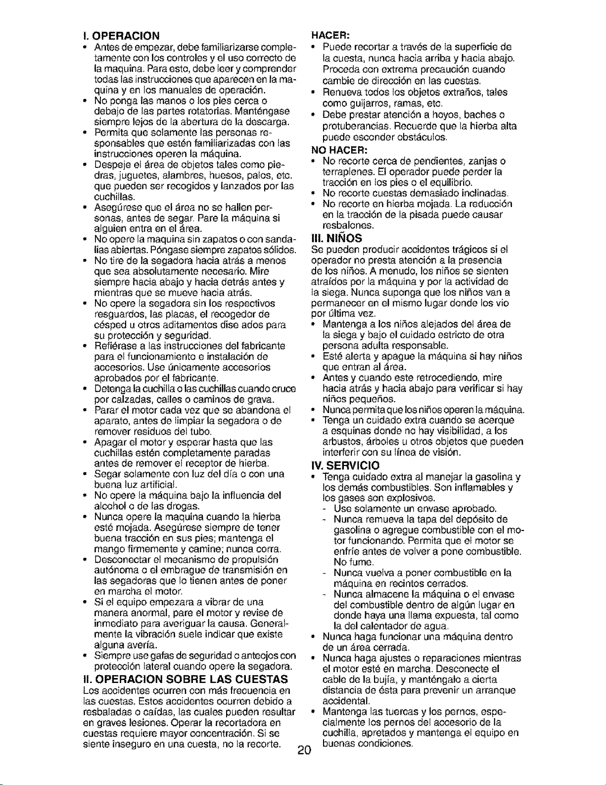
I, OPERAClON
* Antesdeempezar, debefamiliarizarsecomple-
tamente con los controles y el uso correcto de
la maquina. Para esto, debe leer y comprender
todas las instrucciones que aparecen en la ma-
quina yen los manuales de operaciSn.
, No ponga las manos o los pies cerea o
debajo de las partes rotatorias. Mant_ngase
siempre lejos de la abertura de la descarga.
, Permita que solamente las personas re-
sponsables que est#n famitiarizadas con Ias
instrucciones operen la maquina.
, Despeje el area de objetos tales como pie-
dras, juguetes, alambres, huesos, palos, etc.
que pueden ser recogidos y lanzados por las
cuchillas.
, Aseg_rese que el area no se hallen per-
sonas, antes de segar. Pare la mAquina si
alguien entra en el area.
, Nooperelamaquinasinzapatosoconsanda-
lias abiertas. POngase siempre zapatos sSlidos.
, No tire de la segadora hacia atrAs a menos
que sea absolutamente necesario. Mire
siempre hacia abajo y hacia detrAs antes y
mientras que se mueve hacia atrAs.
, No opere la segadora sin los respectivos
resguardos, las placas, el reccgedor de
c_sped u otros aditamentos dise ados para
su protecciSn y seguridad.
, Refi_rase alas instrucciones del fabricante
para el funcionamiento e instalaci6n de
accesorios. Use _nicamente accesorios
aprobados por el fabricante.
, Detenga la cuchilta o las cuchillas euando cruce
pot calzadas, ealles o caminos de grava.
, Parar el motor cada vez que se abandona el
aparato, antes de Iimpiar la segadora o de
remover residuos del tubo.
, Apagar el motor y esperar hasta que las
cuchillas est_n completamente paradas
antes de remover el receptor de hierba.
, Segar solamente con luz del dia o con una
buena luz artificial.
, No opere la maquina ba]o la influencia del
alcohol o de las drogas.
, Nunca opere la maquina cuando Ia hierba
est_ mojada. AsegOrese siempre de tener
buena tracci6n en sus pies; mantenga el
mango firmemente y eamine; nunca corra.
, Desconeetar el mecanismo de propulsiSn
autSnoma o el embrague de transmisiSn en
las segadoras que Io tienen antes de porter
en marcha el motor.
, Si el equipo empezara a vibrar de una
manera anormal, pare el motor y revise de
inmediato para averiguar la causa. General-
mente la vibraciSn suele indicar que existe
alguna averia.
, Siempre use gafas de seguridad o anteojos con ,
protecci6n lateral cuando opere la segadora.
II, OPERAClON SOBRE LAS CUESTAS
Los accidentes ocurren con mas frecuencia en
Ias euestas. Estos accidentes ccurren debido a
resbaladas o caidas, las cuales pueden resultar •
en graves lesiones. Operar la recortadora en
cuestas requiere mayor concentraci6n. Si se
siente inseguro en una cuesta, no Ia recorte.
2O
HACER:
• Puede recortar a tray,s de Ia superfieie de
la cuesta, nunca hacia arriba y hacia abajo.
Prcceda con extrema precauci6n cuando
cambie de direcci6n en las cuestas.
• Renueva todos los objetos extraSos, tales
como guijarros, ramas, etc.
• Debe prestar atenci6n a hoyos, baches o
protuberaneias. Recuerde que Ia hierba alta
puede esconder obstaculos.
NO HACER:
• No recorte cerea de pendientes, zanjas o
terraplenes. El operador puede perder Ia
tracci6n en los pies o el equilibrio.
• No recorte cuestas demasiado inelinadas.
• No recorte en hierba mojada. La reducciSn
en la tracciSn de Ia pisada puede causar
resbalones.
III, NI_IOS
Se pueden producir accidentes trAgicos si el
operador no presta atenciSn a la presencia
de los niSos. A menudo, los niSos se sienten
atraidos por la mAquina y por Ia actividad de
Ia siega. Nunca suponga que los niSos van a
permanecer en el mismo lugar donde los vio
por Oltima vez.
• Mantenga a los niSos alejados del area de
Ia siega y bajo el cuidado estricto de otra
persona adulta responsable.
• Est_ alerta y apague Ia mAquina si hay niSos
que entran al area.
• Antes y euando este retrccediendo, mire
hacia atrAs y hacia abajo para verificar si hay
niSos pequeSos.
• Nunca permita que los ni_os operen la mAquina.
• Tenga un cuidado extra cuando se acerque
a esquinas donde no hay visibitidad, a los
arbustos, arboles u otros objetos que pueden
interferir con su linea de visi6n.
IV, SERMIClO
• Tenga cuidado extra al manejar la gasolina y
los demas combustibles. Son inflamables y
los gases son explosivos.
- Use solamente un envase aprobado.
- Nunca remueva la tapa deI dep_,sito de
gasolina o agregue combustible con el mo-
tor funcionando. Permita que el motor se
enfrie antes de volver a pone combustible.
No fume.
- Nunca vuetva a porter combustible en la
mAquina en recintos cerrados.
- Nunca almacene la maquina o el envase
del combustible dentro de alg_n lugar en
donde haya una llama expuesta, tal como
la del calentador de agua.
Nunca haga funcionar una maquina dentro
de un Area eerrada.
Nunea haga ajustes o reparaciones mientras
el motor est_ en marcha. Desccnecte el
cable de la bujia, y mant_ngalo a eierta
distancia de _sta para prevenir un arranque
accidental.
Mantenga las tuercas y los pemos, espe-
cialmente los pernos del accesorio de la
cuchilla, apretados y mantenga el equipo en
buenas condiciones.
• Nuncamanipuledeformaindebidalos
dispositivosdeseguridad.Controleregular-
mentesufuncionamientocorrecto.
• MantengalamAquinalibredehierba,hojas
uotrasacumulacionesdedesperdieio.
Limpielosderramesdeaceiteecombustible.
PermitaquelamAquinaseenfrle antes de
almacenarla.
• Pare e inspeccione el equipo si le pega a un
objeto. RepArelo, si es necesario, antes de
hacerlo arrancar.
• En ningfin case hay que regular la altura de
las ruedas mientras e! motor est_ en marcha.
. Los componentes del receptor de la hierba
van sujetos a desgaste, da_os y deterioro,
que pueden exporter las partes en mov-
imiente o permitir que objetos scan dispara-
dos. Controlar frecuentemente y cuando sea
necesario sustituir con partes aconsejadas
per el fabricante.
. Las cuchillas de la segadera est_n afiladas y
pueden cortar. Cubrir las hojas e Ilevar guantes,
y utilizar precauciones especiales euando se
efectOa mantenimiento sobre Ias mismas.
° No cambie el ajuste del regulador del motor
ni exceda su ve!ocidad.
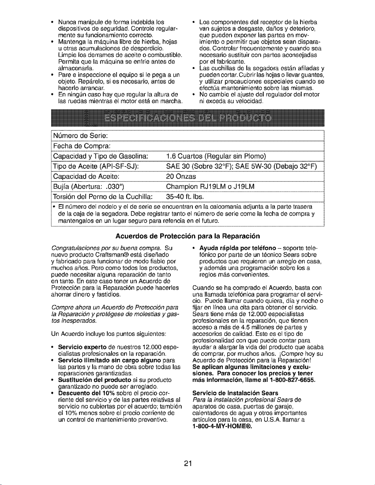
N6mero de Serie:
Fecha de Compra:
Capacidad y Tipo de Gasolina: 1.6 Cuartos (Regular sin Plomo)
Tipo de Aceite (API-SF-SJ): SAE 30 (Sobre 32°F); SAE 5W-30 (Debajo 32°F)
Capacidad de Aceite: 20 Onzas
Buj[a (Abertura: .030") Champion RJ19LM o J19LM
Torsi6n del Perno de la Cuchilla: 35-40 ft. Ibs.
El n_mero del nodelo y el de serie se encuentran en la calcomania adjunta a la parte trasera
de la caja de Ia segadora. Debe registrar tanto et nOmero de serie come la fecha de compra y
mantengalos en un lugar seguro para refeneia en el futuro.
Acuerdos de Protecci6n para la Reparaci6n
Congmtulaciones per su buena cempm. Su
nuevo producto Craftsmar_ est_ diseSado
y fabricado para funcionar de modo fiable per
muchos aSos. Pete come todos los produetos,
puede necesitar alguna reparaci6n de tante
en tanto. En este case tener un Acuerdo de
Protecci6n para la Reparaci6n puede hacerles
ahorrar dinero y fastidios.
Compre ahem un Acuetdo de Proteccidn para
ta RepaFaci6n y prot#gese de mefestias y gas-
tes inesperados.
Un Acuerdo incluye los puntos siguientes:
• Servicio experto de nuestros 12.000 espe-
cialistas profesionales en la reparaci6n.
• Servicio ilimitado sin cargo alguno para
las partes y la mane de obra sobre todas las
reparaciones garantizadas.
• Sustituci6n del producto si su producto
garantizade no puede set arreglado.
• Descuento de110% sobre el precio eor-
riente del servicio y de las partes relativas al
servicio no cubiertas per el acuerdo; tambi_n
el 10% menos sobre el precio corriente de
un control de mantenimiento preventivo.
. Ayuda rdpida pot telefono - soporte tele-
f6nico pot parte de un t_cnico Sears sobre
productos que requieren un arreglo en casa,
y adem_s una pregramaci6n sobre los a
reglos m&s convenientes.
Cuando se ha comprado el Acuerdo, basta con
una Ilamada telef6nica para programar el servi-
eio. Puede Ilamar cuando quiera, dia y noche o
fijar en I[nea una cita para ebtener el servicio.
Sears tiene mAs de 12.000 especialistas
profesionales en Ia reparaci6n, que tienen
acceso a m_s de 4.5 railleries de partes y
accesorios de calidad. Este es el tipo de
profesionalidad con que puede contar para
ayudar a alargar la vida del producto que acaba
de eomprar, pot touches aSos. iCompre boy su
Aeuerdo de Protecci6n para la Reparaci6n!
Se aplican algunas limitaeiones y exelu-
siones. Para conocer los precios y tenet
mas informaci6n, Ilame al 1-800-827-6655.
Servicio de Instalaci6n Sears
Para la instafaci6n profesiona! Sears de
aparatos de casa, puertas de garaje,
calentadores de agua y otros importantes
artieulos para la easa, en U.S.A. Ilamar a
1-800-_MY-HOME®.
21
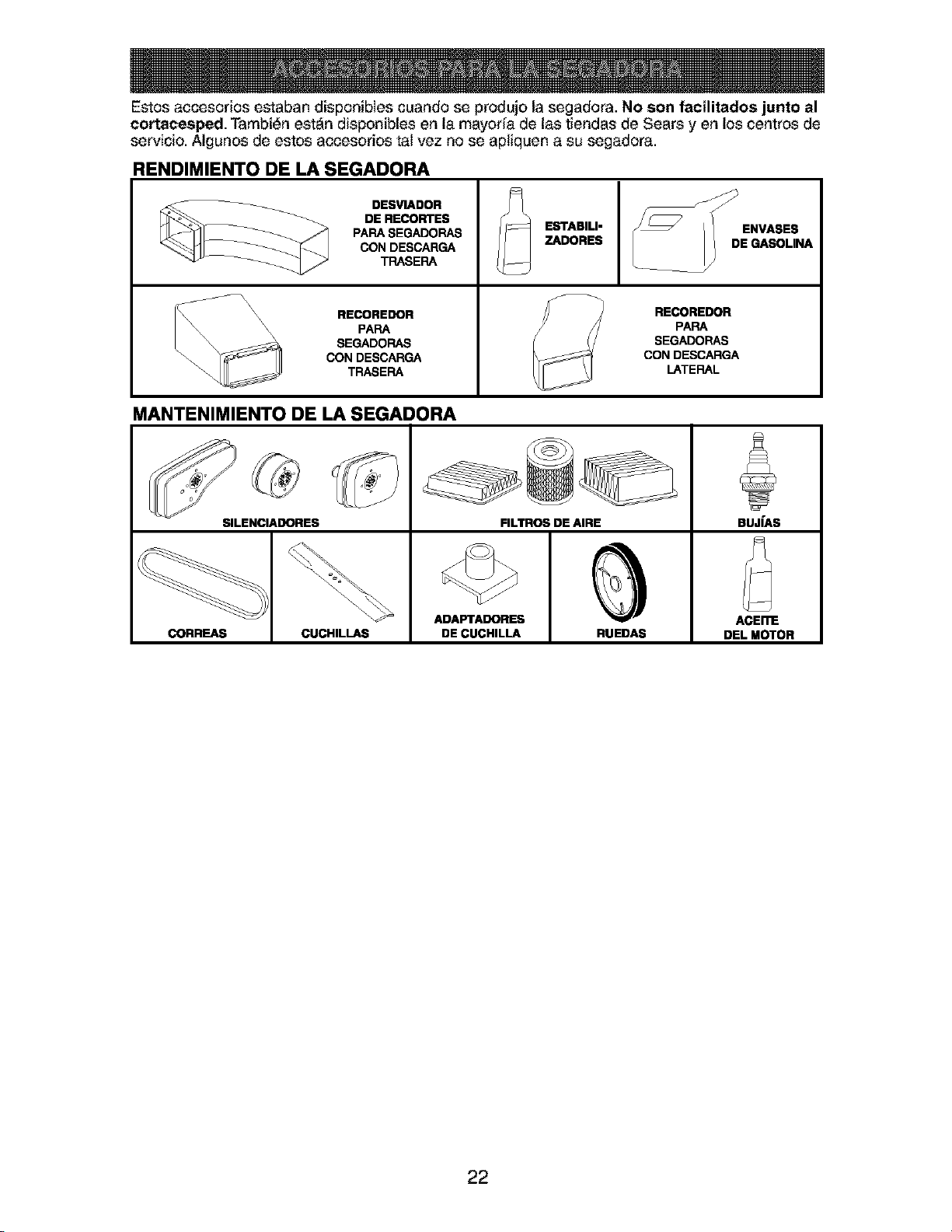
Estos accesorios estaban disponibles cuando se produjo la segadora. No son facilitados junto al
cortacesped. Tambi_n est_n disponibles en la mayor[a de las tiendas de Sears yen los centros de
servicio. Algunos de estos accesorios tal vez no se apliquen a su segadora.
RENDIMIENTO DE LA SEGADORA
__ DESVIADOR
DE RECORTES
PARA SI=GADORAS
CON DESCARGA
TRASERA
\\ RECOREDOR
_\\ \\ PAPA
SEGADORAS
CON DESCARGA
TRASERA
ESTABILI-
ZADORES
RECOREDOR
PARA
SEGADORAS
CON DESCARGA
LATERAL
MANTENIMIENTO DE LA SEGADORA
SILENCIADORES FILTROS DE AIRE BUJfAS
ADAFrAI_RES ACEI_
CORREAS CUCHILLAS DE CUCHILLA RUEDAS DEL MOTOR
22
Lea estas instrucciones y este manual comple-
tamente antes de tratar de montar u operar su
segadora nueva.
IMPORTANTE: Este cortac_sped viene SIN
ACEITE O GASOLINA en el motor.
Su segadora nueva ha sido montada en la
f_brica con la excepci6n de aquellas partes que
se dejaron sin montar pot razones de envio.
Todas las partes eomo las tuercas, las arande-
Ias, los pernos, etc., que son necesarias para
completar el montaje ban sido colocadas en Ia
bolsa de partes. Para asegurarse que su sega-
dora funcione en forma segura y adecuada,
todas las partes y los articulos de ferreteria que
se monten tienen que set apretados segura-
mente. Use las herramientas correctas, como
sea necesario, para asegurar que se aprieten
adecuadamente.
PARA REMOVER LA SEGADORA DE
LA CAJA DE CARTON
1. Remueva las partes sueltas que se inctuyen
con la segadora.
2. Corte las dos esquinas de los extremos
de la caja de eart6n y tienda el panel del
extremo piano.
3. Remueva todo e! material de empaque, ex-
cepto la cuSa entre el mango superior y 61
inferior, y la cuSa que sujeta la barra de los
control que exige la preseneia del operador
junto con el mango superior.
4. Haga rodar la segadora hacia afuera de la
caja de cart6n y revisela euidadosamente
para verificar si todavia quedan partes
sueltas adicionales.
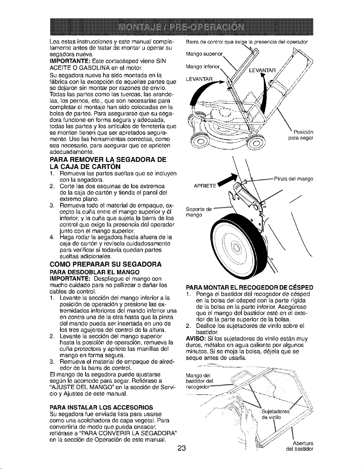
COMO PREPARAR SU SEGADORA
PARA DESDOBLAR EL MANGO
IMPORTANTE: Despliegue el mango con
mucho cuidado para no pellizcar o daSar los
cables de control.
1. Levante Ia secci6n de! mango inferior a la
posici6n de operaci6n y presione las ex-
tremidades inferiores del mando inferior una
en eontra una de Ia otra hasta que la pinza
del mando pueda set insertada en uno de
los tres agujeros del control de la altura.
2. Levante la secei6n del mango superior
hasta la posici6n de operaci6n, remueva la
euSa protectora y apriete las manillas del
mango en forma segura.
3. Remueva el material de empaque de alred-
edor de la barra de control.
El mango de la segadora puede ajustarse
seg_n le acomode para segar. Refi6rase a
"AJUSTE DEL MANGO _en ta secci6n de Servi-
cio y Ajustes de este manual.
Barra de conlroI c
Mango superior
Mango Inferior
LEVANTAR
ta presencia det operador
Posici6n
para segar
a del mango
Soporte de
mango
J
PARA MONTAR EL RECOGEDOR DE CESPED
1. Ponga el bastidor del recogedor de c_sped
en la bolsa del c_sped con la parte dgida
de la bolsa en la parte inferior. Aseg_rese
que el mango del bastidor est_ en el exte-
rior de la parte superior de la bolsa.
2. Deslice los sujetadores de vinilo sobre el
bastidor.
AVISO: Si los sujetadores de vinito est_n muy
duros, m6talos en agua caliente pot algunos
minutos. Si se moja la botsa, d_jela que se
seque antes de usarla.
Mango deI ,.y,_
bastidor del x,,
recogedor
PARA INSTALAR LOS ACCESORIOS
Su segadora fue enviada lista para usarse
como una acolchadora de capa vegetal. Para
convertirla de modo que pueda ensacar,
refi_rase a "PARA CONVERIR LA SEGADORA _
en Ia secci6n de Operaci6n de este manual.
23
Abertura
del bastidor
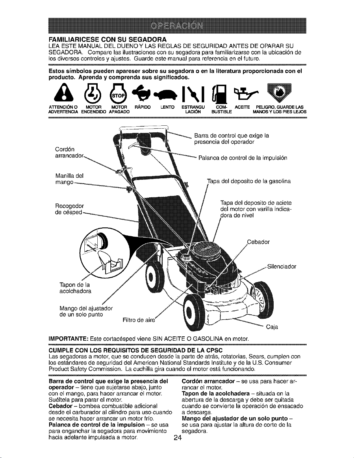
FAMILIARICESE CON SU SEGADORA
LEA ESTE MANUAL DEL DUENOY LAS REGLAS DE SEGURIDAD ANTES DE OPARAR SU
SEGADORA. Compare las ilustraciones con su segadora para famitiarizarse con la ubicaci6n de
los diversos controles y ajustes. Guarde este manual para referencia en el futuro.
w ,,,
Estos simbolos pueden apareser sobre su segadora o en la literatura proporcionada con el
producto. Aprenda y comprenda sus significados.
A'n'ENCI6N O MOTOR MOTOR RAPIDO LENTO ESTRANGU COM- ACEITE PELIGRO, GUARDE LAS
ADVERTENCIA ENCENDIDO APAGADO LACI(SN BUSTIBLE MANOS Y LOS PIES LEJO8
Cord6n
Barra de control que exige Ia
presencia del operador
Palanca de control de la impulsi6n
Manilla del
del deposito de Ia gasolina
Recogedor
Tapa del deposito de aciete
del motor con varilla indica-
dora de nivel
Tapon deia
acolchadora
Mango del_ustador
de un solo punto
Filtro de aire
caja
IMPORTANTE: Este cortac_sped viene SIN ACEITE O GASOLINA en motor.
CUMPLE CON LOS REQUISITOS DE SEGURIDAD DE LA CPSC
Las segadoras a motor, que se conducen desde la parte de atr_s, rotatorias, Sears, cumplen con
los est_ndares de seguridad del American National Standards Institute y de la U.S. Consumer
Product Safety Commission. La cuchilla gira cuando el motor est_ funcionando.
Barra de control que exige la presencia del
operador - tiene que sujetarse abajo, junto
con el mango, para hacer arrancar el motor.
Su_ltela para parar el motor.
Cebador - bombea combustible adicionaI
desde el carburador al cilindro para uso cuando
se necesita hacer arrancar un motor frio.
Palanca de control de la impulsion -se usa
para enganchar la segadora para movimiento
hacia adelante impulsada a motor.
Cord6n arrancador - se usa para hacer ar-
rancar el motor.
Tapon de la acolchadera - situada en la
abertura de la descarga y debe set quitada
cuando se convierte la operaci6n de ensacado
a descarga.
Mango del ajustador de un solo punto -
se usa para ajustar Ia altura de corte de la
segadora.
24
Laoperaci6ndecualquier
segadorapuedehacerque
saltenobjetosextraSosdentrode
susojos,Ioquepuedeproducir
daSosgravesen _stos. Siempre
use anteojos de seguridad o protecci6n para
los ojos mientras opere su segadora o cuando
haga ajustes o reparaciones. Recomendamos
gafas ouna mascara de seguridad de visi6n
amplia de seguridad usada sobre las gafas.
COMO USAR sg SEGADORA
VELOCIDAD DEL MOTOR
La velocidad del motor se estableci6 en la f_-
brica para un rendimiento 6ptimo, La velocidad
no se puede ajustar,
_NTROL DE ZONA DEL MOTOR
PRECAUCION: Las regulaciones federales
exigen que se instale un control para el motor
en esta segadora para reducir a un minimo el
riesgo de Iesionarse debido aI contacto con la
cuchilla. Pot ning_n motivo trate de eliminar
Ia funci6n del control del operador. La cuchilla
gira cuando el motor est_ funcionando.
• Su segadora viene equipada con una barra
de controles que exigen la presencia del
operador, Io que requiere que el operador
est_ detr_s del mango de la segadora para
hacerla arrancar y operarla.
CONTROL DE LA IMPULSION
• La autopropulsi6n se controla manteniendo
la palanca de mando operador presente
abajo hacia el mango y tirando la palanca de
accionamiento atr_s hacia el mango. Cuanto
m&s lejos se tira la palanca hacia el mango,
m_,s r&pida Jr&la unidad.
• El movimiento hacia adelante se detiene
cuando sea la palanca de mando operador
presente o la palanca de accionamiento se
sueltan. Para detener e! movimiento hacia
adelante sin apagar el motor, soltar s61o
la palanca de accionamiento. Mantener la
palanca de mando operador presente abajo
contra el mango para continuar a cortar sin
autopropulsi6n.
AVISO: Si despu_s haber desenganchado de Ia
palanca de control, la segadora no roda hacia
atrAs, empuje la segadora un poco hacia adetante
para desenganchar las ruedas de la impulsiSn.
Barra de control que
PARA
Bot6n aiuste ENGANCHAR EL
(en la parte CONTROL DE LA
trasera) IMPULSION
C_ntroi
la impulsi6r
CONTROL DE LA
IMPULSION
DESENGANCHADO
AJUSTE DEL MANDO
Ocasionalmente, e! sistema de mando puede
"aflojarse", provocando una disminuci6n de la
velocidad. Hay un botSn en la parte trasera de
Ia sede del mando para apretar la tensiSn del
cable. Proceder de Ia siguiente manera:
1. Apagar la unidad y desconectar el cable de
bujia de Ia bujla.
2. Tirar la palanca de accionamiento TODO
ATR,_S HACIA el mango.
3. Empujar el bot6n en la parte trasera del
mando. Con el botSn apretado, revuelva la
palanca de controles del mecanismo impul-
sot a Ia posici6n desenganchada TODO
DELANTERO HACIA el mango.
AVISO: No el trinquete el ajuste.
4. Soltar el bot6n.
5. Opere la segadora para probar Ia velocidad
del mecanismo. Sitras los pasos descritos ar-
riba la situaciSn se empeora (la velocidad de
avarice ha disminuido), el sistema no estaba
"aflojadd'. Repitiendo los pasos de arriba se
vueke la unidad aIajuste y velocidad correctos.
6. Si tas condiciones no mejoran despu_s de los
pasos descritos (la velocidad hacia adelante
queda Ia misma), la correa de transmisiSn
est_ desgastada y tiene que set sustituida.
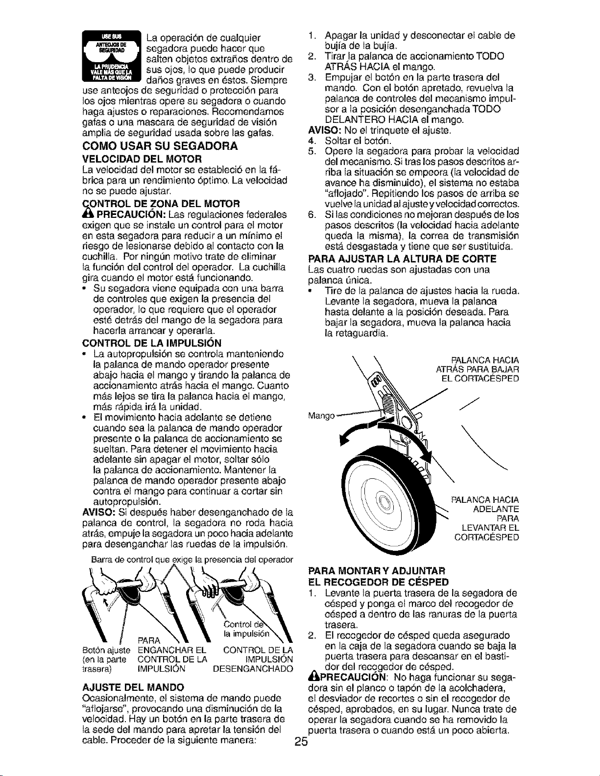
PARA AJUSTAR LA ALTURA DE CORTE
Las cuatro ruedas son ajustadas con una
palanca _nica.
• Tire de la palanca de ajustes hacia la rueda.
Levante la segadora, mueva la palanca
hasta delante a la posiciSn deseada. Para
bajar la segadora, mueva la palanca hacia
la retaguardia.
Mang
PALANCA HACIA
ATR,_S PARA BAJAR
EL CORTACESPED
J
PALANCA HACIA
ADELANTE
PARA
LEVANTAR EL
CORTACESPED
PARA MONTAR Y ADJUNTAR
EL RECOGEDOR DE CESPED
1. Levante la puerta trasera de la segadora de
c_sped y ponga el marco del recogedor de
c_sped a dentro de las ranuras de Ia puerta
trasera,
2. El recogedor de c_sped queda asegurado
en la caja de la segadora cuando se baja la
puerta trasera para descansar en el basti-
_il dot del recogedor de c_sped.
PRECAUCION: No haga funcionar su sega-
dora sin el planco o tapSn de la acolchadera,
el desviador de recortes o sin el recogedor de
c#sped, aprobados, en su lugar. Nunca trate de
operar la segadora cuando se ha removido la
puerta trasera o cuando estA un poco abierta.
25
Ranuras de ta Puerta
Mango det
bastidor del
recogedor de
c_sped
Gancho lateral del
bastidor del recogedor
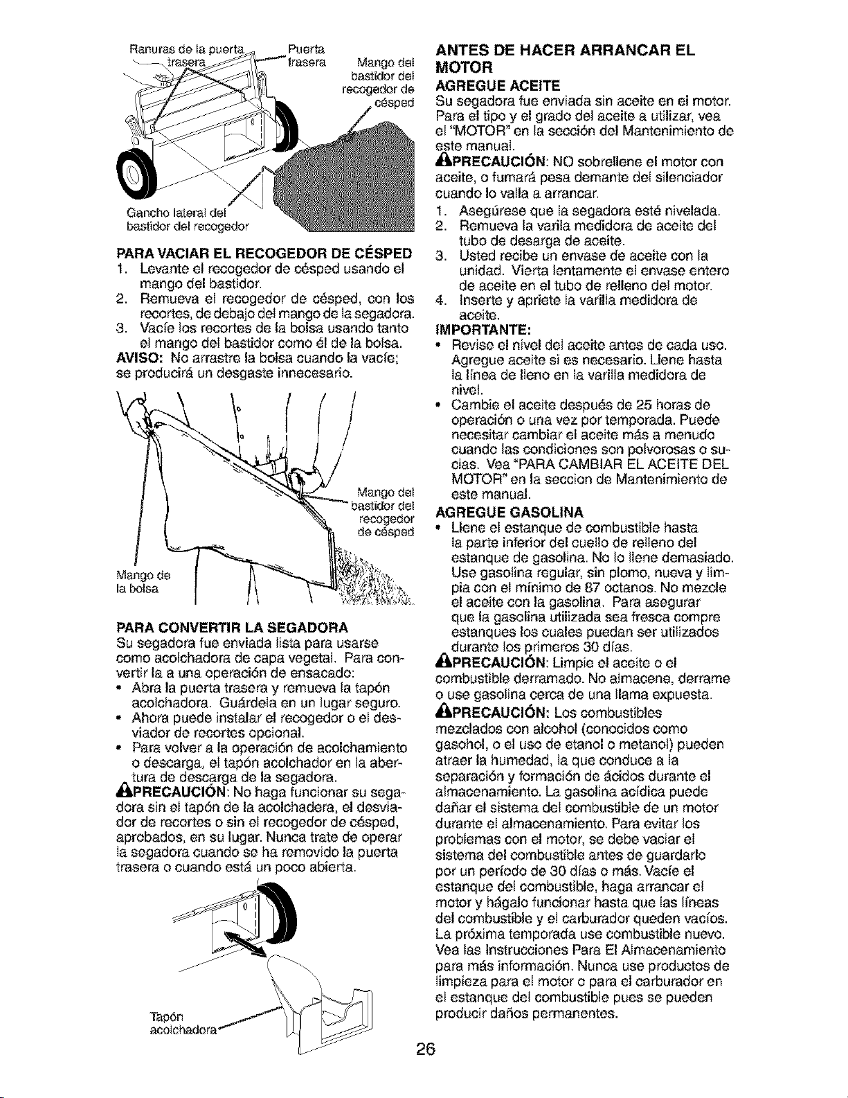
PARA VACIAR EL RECOGEDOR DE CESPED
1. Levante el recogedor de c_sped usando el
mango del bastidor.
2. Remueva el recogedor de c_sped, con los
recortes, de debajo del mango de Iasegadora.
3. Vacie los recortes de la bolsa usando tanto
el mango deI bastidor como 61de la bolsa.
AVISO: No arrastre la bolsa cuando la vacie;
se producir,_ un desgaste innecesario.
/
Mango det
recogedor
de c_sped
Mango de
la bolsa
PARA CONVERTIR LA SEGADORA
Su segadora fue enviada lista para usarse
como acolchadora de capa vegetal. Para con-
vertir la a una operaciSn de ensacado:
• Abra la puerta trasera y remueva la tap6n
acolchadora. Gu,_rdela en un lugar seguro.
• Ahora puede instalar el recogedor o el des-
viador de recortes opcional.
• Para volver a la operaci6n de acolchamiento
o descarga, el tap6n acolchador en la aber-
A(:tura de descarga de la segadora.
PRECAUCION: No haga funcionar su sega-
dora sin el tap6n de la acolchadera, el desvia-
dot de recortes o sin el recogedor de e_sped,
aprobados, en su lugar. Nunca trate de operar
Ia segadora euando se ha removido la puerta
trasera o cuando est,_ un poco abierta.
Tap6n
acotchadora'
ANTES DE HACER ARRANCAR EL
MOTOR
AGREGUE ACEITE
Su segadora fue enviada sin aceite en el motor.
Para el tipo y el grado del aceite a utilizar, vea
el "MOTOR" en la secci6n del Mantenimiento de
este manual.
_PRECAUOI6N: NO sobrellene el motor con
aceite, o fumar_ pesa demante del silenciador
cuando Io valla a arrancar.
1. AsegOrese que Ia segadora est_ nivelada.
2. Remueva la varila medidora de aceite deI
tubo de desarga de aceite.
3. Usted recibe un envase de aceite con la
unidad. Vierta lentamente el envase entero
de aceite en el tubo de relleno del motor.
4. Inserte y apriete Ia varilla medidora de
aeeite.
IMPORTANTE:
• Revise el nivel del aceite antes de cada uso.
Agregue aeeite si es neeesario. Llene basra
Ia linea de Ileno en Ia varitta medidora de
niveI.
• Cambie el aceite despu_s de 25 horas de
operaci6n o una vez pot temporada. Puede
necesitar cambiar el aceite m,_s a menudo
cuando las condiciones son potvorosas o su-
cias. Vea "PARA CAMBIAR EL ACEITE DEL
MOTOR" en la seccion de Mantenimiento de
este manual.
AGREGUE GASOLINA
• Llene el estanque de combustible hasta
Ia parte inferior del cuello de retleno del
estanque de gasolina. No Io Ilene demasiado.
Use gasotina regular, sin plomo, nueva y Iim-
pia con el minimo de 87 octanos. No mezcle
el aceite con la gasolina. Para asegurar
que la gasolina utilizada sea fresca compre
estanques los cuales puedan set utilizados
durante los primeros 30 dfas.
_kPRECAUCION: Limpie el aceite o el
combustible derramado. No aImacene, derrame
o use gasolina cerca de una llama expuesta.
,_PRECAUCI6N: Los combustibles
mezclados con alcohol (conocidos como
gasohol, o el uso de etanol o metanol) pueden
atraer la humedad, la que conduce a Ia
separaciSn y formaciSn de _eidos durante el
almacenamiento. La gasolina addica puede
daSar el sistema del combustible de un motor
durante el almacenamiento. Para evitar los
problemas con el motor, se debe vaciar el
sistema del combustible antes de guardarlo
por un periodo de 30 dfas o m_s. Vacie el
estanque del combustible, haga arrancar el
motor y h_galo funcionar hasta que Ias lineas
del combustible y et carburador queden vados.
La pr6xima temporada use combustible nuevo.
Vea las Instrucciones Para El Almacenamiento
para rods informaci6n. Nunca use productos de
Iimpieza para eI motor o para el carburador en
el estanque del combustible pues se pueden
producir daSos permanentes.
26
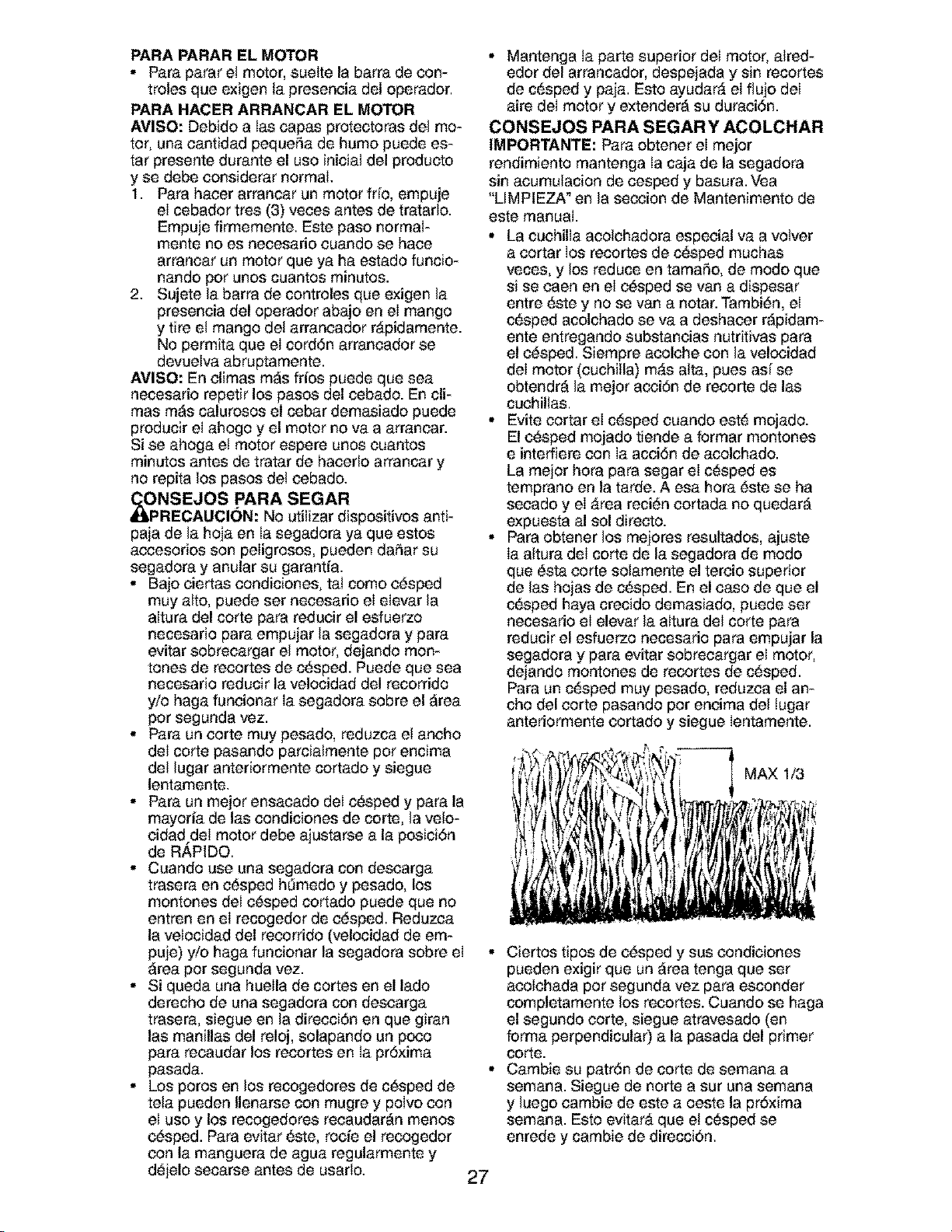
PARA PARAR EL MOTOR
• Para parar e! motor, suelte la barra de con-
troles que exigen ta preseneia del operador.
PARA HACER ARRANCAR EL MOTOR
AVISO: Debido alas capas protectoras del mo-
tor, una cantidad pequeSa de humo puede es-
tar presente durante el uso inicial del producto
y se debe eonsiderar normai.
1. Para hacer arrancar un motor frio, empuje
ei cebador tres (3) veces antes de tratarlo.
Empuje firmemente. Este paso normal-
mente no es necesario euando se hace
arrancar un motor que ya ha estado funcio-
nando pot unos cuantos minutos.
2. Sujete la barra de controles que exigen la
presencia del operador abajo en el mango
y tire el mango del arrancador r&pidamente.
No permita que el cord6n arrancador se
devuelva abruptamente.
AVISO: En climas mas frios puede que sea
necesario repetir los pasos del cebado. En cli-
mas mas calurosos el cebar demasiado puede
producir el ahogo y el motor no va a arrancar.
Si se ahoga et motor espere unos cuantos
minutos antes de tratar de hacerlo arrancar y
no repita los pasos det eebado.
dI_ONSEJOS PARA SEGAR
RECAUCI()N: No utilizar dispositivos anti-
paja de la hoja en Ia segadora ya que estos
accesorios son peligrosos, pueden daSar su
segadora y anular su garantia.
• Bajo eiertas condiciones, tal como e_sped
muy alto, puede set necesario el elevar la
altura del corte para reducir el esfuerzo
necesario para empujar la segadora y para
evitar sobrecargar el motor, dejando mort-
tones de recortes de c_sped. Puede que sea
necesario reducir la velocidad del recorrido
y/o haga funcionar Ia segadora sobre el area
pot segunda vez.
• Para un corte muy pesado, reduzca et ancho
del corte pasando parcialmente pot encima
del lugar anteriormente cortado y siegue
lentamente.
• Para un mejor ensacado deI c_sped y para la
mayoria de las condiciones de corte, la velo-
cidad deI motor debe ajustarse a la posici6n
de R_,PIDO.
• Cuando use una segadora con descarga
trasera en c_sped hOmedo y pesado, los
montones del c_sped cortado puede que no
entren en el recogedor de e_sped. Reduzca
la velocidad del recorrido (velocidad de em-
puje) yio haga funcionar la segadora sobre el
area pot segunda vez.
• Si queda una huella de cortes en el lado
derecho de una segadora con descarga
trasera, siegue en la direcciOn en que giran
las manillas del reloj, solapando un poco
para recaudar los recortes en Ia pr6xima
pasada.
• Los poros en los recogedores de c_sped de
tela pueden Ilenarse con mugre y polvo con
el uso y los recogedores recaudaran menos
c_sped. Para evitar _ste, rocie el recogedor
con la manguera de agua regularmente y
d_jelo secarse antes de usarlo.
27
• Mantenga ia parte superior del motor, aired-
edor del arrancador, despejada y sin recortes
de c_sped y paja. Esto ayudar_ el flujo del
aire del motor y extendera su duraci6n.
CONSEJOS PARA SEGAR Y ACOLCHAR
IMPORTANTE: Para obtener el mejor
rendimiento mantenga la caja de la segadora
sin acumulacion de cesped y basura. Vea
"LIMPIEZA _en la seccion de Mantenimento de
este manual.
• La cuchilla acolchadora especial va a votver
a cortar los recortes de c_sped muchas
veces, y los reduce en tamaSo, de modo que
si se caen en el c_sped se van a dispesar
entre _ste y no se van a notar. Tambi_n, el
c_sped acolchado se va a deshacer rapidam-
ente entregando substaneias nutritivas para
el e_sped. Siempre acolche con la velocidad
del motor (cuchilla) m_s alta, pues asf se
obtendra la mejor acciOn de recorte de las
cuehillas.
• Evite cortar el c_sped cuando este mojado.
El e_sped mojado tiende a format montones
e interfiere con Ia acci6n de acolchado.
La mejor hora para segar el c_sped es
temprano en la tarde. A esa hora _ste se ha
secado y el _rea reci_n cortada no quedara
expuesta al sol direct&
• Para obtener los mejores resultados, ajuste
Ia altura del corte de la segadora de modo
que _sta eorte solamente el tereio superior
de las hojas de c_sped. En el caso de que el
c_sped haya crecido demasiado, puede set
necesario el elevar la altura del corte para
reducir el esfuerzo necesario para empujar la
segadora y para evitar sobrecargar el motor,
dejando montones de recortes de c_sped.
Para un c_sped muy pesado, reduzca el an-
cho del corte pasando pot encima del tugar
anteriormente cortado y siegue Ientamente.
MAX 1/3
• Ciertos tipos de c_sped y sus condiciones
pueden exigir que un area tenga que set
acolchada pot segunda vez para esconder
completamente los recortes. Cuando se haga
el segundo corte, siegue atravesado (en
forma perpendicular) a la pasada del primer
COrte.
• Gamble su patr6n de corte de semana a
semana. Siegue de norte a sur una semana
y luego cambie de este a oeste la pr6xima
semana. Esto evitar& que e! c_sped se
enrede y cambie de direcci6n,
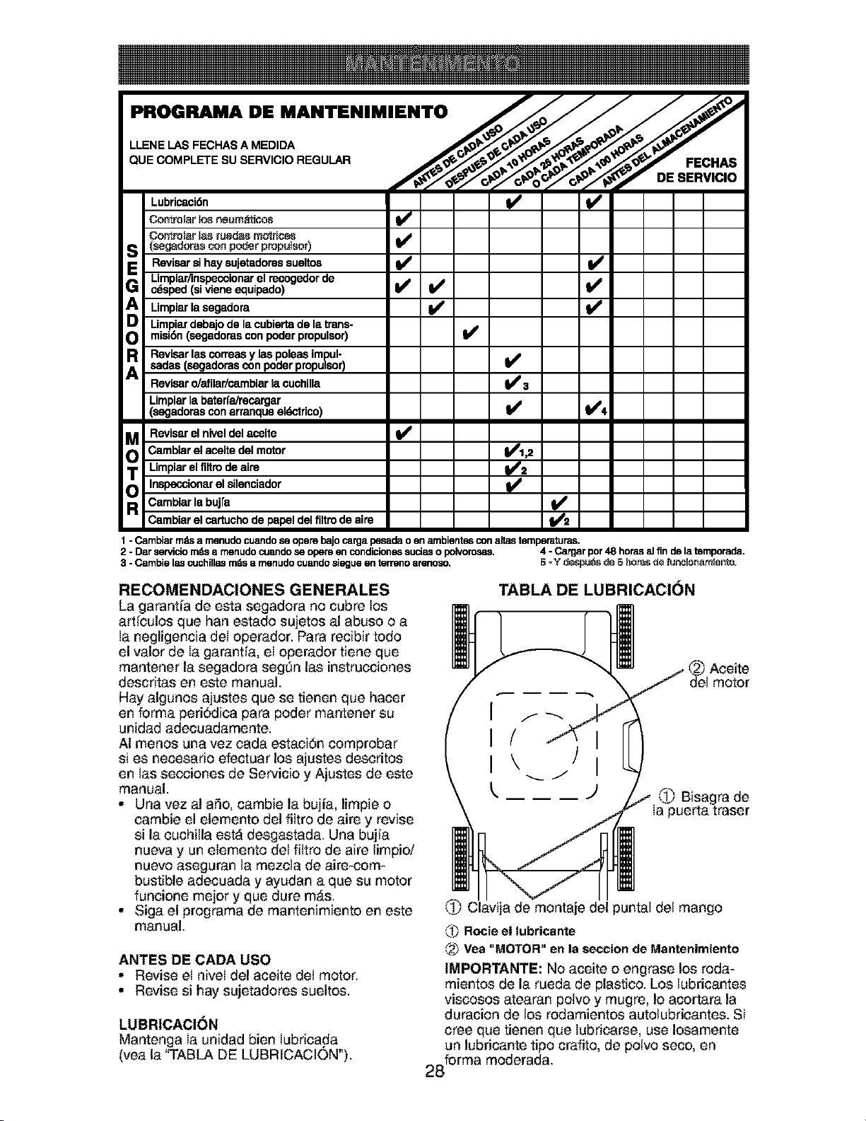
Lubricaci6n ql_
Controlar log neurn_ticos
v
Controlarlagruadasmotriceg
S (gegadoras con poder propuigor)Revisarsihaysujetadoressueltco V' V'
Limpiar.,1nspecoionarel recogedor de I_
G c_sped (si viene equipado) I_ _
,!
Uropiar la segadora
Umpiar debajo de la cubiertade la trans-
misidn(segadorasconpoderpropulsor)
R Revisarlascorreasylaspoleasimpul-
sadas (segadoras con poder propulsor) 11_
Revisaro/afilar/cambiarlacuchilla V' 3
Limpiarla baterfa/recargar
(segadorasconarranqueeldctrico) l## _4
a Revisarelniveldelacelte
Cambiar el aceite del motor _1,2
Limpiar el filtro de airo _2
O Inspecci°nar el silenciad°r _ _2
Cambiar la buj[a
Cambiar el cortucho de papel del filtro de aire
1 - Cambiarmdsa menudocuandoseopensbajocarga pesadao en ambientesconaltastemperaturas.
2 - Darservidomdsa menudocuandose opere encondicionessudas o polvorosas. 4 - Cargarpor48 horasal finde latemporada.
3 - Cambielascuchillasmdsa menudocuandosiggueen terrenoarenoso. 5 =Y despuds de 5 h_re_de funcmonamlento,
RECOMENDACIONES GENERALES
La garantia de esta segadora no cubre Ios
artieulos que hart estado sujetos al abuso o a
Ia negligencia del operador. Para recibir todo
el valor de Ia garantia, el operador tiene que
mantener la segadora segOn las instrucciones
descritas en este manual.
Hay algunos ajustes que se tienen que hacer
en forma perid,dica para poder mantener su
unidad adecuadamente.
AI menos una vez cada estacidn comprobar
si es necesario efectuar los ajustes descritos
en las secciones de Servicio y Ajustes de este
manual.
• Una vez al a_o, cambie la bujia, limpie o
cambie el elemento del filtro de aire y revise
si la cuchilla est_ desgastada. Una bujia
nueva y un elemento del filtro de aire limpio/
nuevo aseguran la mezcla de aire-com-
bustible adecuada y ayudan a que su motor
funcione mejor y que dure m,_s.
• Siga el programa de mantenimiento en este
manual.
ANTES DE CADA USO
• Revise el nivel del aceite del motor.
• Revise si hay sujetadores sueltos.
LUBRICACION
Mantenga Ia unidad bien iubricada
(vea la "TABLA DE LUBRICAClON').
TABLA DE LUBRICACI(_N
@ Aceite
del motor
J _ Bisagra de
)uerta traser
Ci_.vija de montaje del puntal del mango
(')_ Rocieel tubricante
(2_Vea "MOTOR" en la section de Mantenimiento
IMPORTANTE: No aceite o engrase los roda-
mientos de la rueda de plastic& Los lubricantes
viseosos atearan polvo y mugre, Io acortara la
duracion de los rodamientos autotubricantes. Si
cree que tienen que Iubricarse, use Iosamente
un lubricante tipo crafito, de polvo seco, en
28forma moderada,
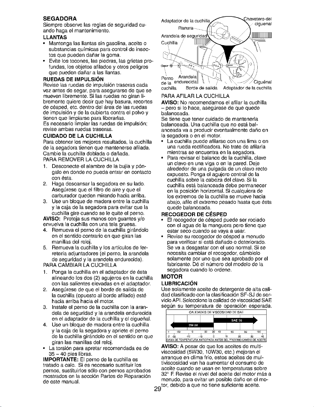
SEGADORA
Siempre observe las reglas de seguridad cu-
ando haga el mantenimiento.
LLANTAS
• Mantenga las Ilantas sin gasolina, aceite o
substancias qu[micas para control de insec-
tos que pueden daSar Ia goma.
• Evite los tocones, las piedras, las grietas pro-
fundas, los objetos afilados y otros peligros
que pueden daSar a las Ilantas.
RUEDAS DE IMPULSI()N
Revise las ruedas de imputsi6n traseras cada
vez antes de segar, para asegurarse de que se
mueven libremente. Si las ruedas no giran li-
bremente quiere decir que hay basura, recortes
de c_sped, etc. dentro del Area de las ruedas
de impulsi6n y de la cubierta contra el polvo y
tienen que limpiarse para liberarlas.
Es necesario Iimpiar las ruedas de impulsiSn;
revise ambas ruedas traseras.
CUIDADO DE LA CUCHILLA
Para obtener los mejores resultados, Ia cuchilla
de la segadora tienen que mantenerse afilada.
Cambie la cuchilla doblada o daSada.
PARA REMOVER LA CUCHILLA
1. Desconecte el alambre de la bujia y p6n-
galo en donde no pueda entrar en contacto
con _sta.
2. Haga descansar la segadora en su lado.
Ase@rese que el filtro de aire y que el
carburador queden mirando hacia arriba.
3. Use un bloque de madera entre Ia cuchilla
y la caja de la segadora para evitar que la
cuchilla gire cuando se le quite el pemo.
AVISO: Proteja sus manos con guantes y/o
envuetva la cuchilla con una tela gruesa.
4. Remueva el pemo de Ia cuchilla gir&ndolo
en el sentido contrario en que giran Ias
manillas del reloj.
5. Remueva la cuchilla y los articulos de fer-
reteria adjuntadores (el pemo, la arandela
de seguridad y la arandela endurecida).
PARA CAMBIAR LA CUCHILLA
1. Ponga la cuchilla en el adaptador de _sta
alineando los dos (2) agujeros en la cuchilla
con las salientes elevadas en el adaptador.
2. Ase@rese de que el borde de salida de
la cuchilla (opuesto al horde afilado) est_
hacia arriba hacia el motor.
3. Instale el pemo de la cuchilla con la aran-
dela de seguridad y la arandela endurecida
en el adaptador de la cuchilla y el cigueSal.
4. Use un bloque de madera entre la cuchilla
y la caja de la segadora y apriete el pemo
de la cuchitla gir&ndolo en et sentido en que
giran las manillas del reloj.
• La torsiSn para apretar recomendada es de
35 - 40 pies libras.
IMPORTANTE: El pemo de la cuchilla es
tratado a calo. Si es necesario sustituir los
pemos, sustituirlos sSIo con pemos aprobados
mostrados en ta secci6n Partes de Reparaci6n
de este manual.
ciguenat
'\
\
Pemo
de la endurecida \ Cigu_nat
cuchitla Borde de satida Adaptador de la cuchitla
PARA AFILAR LA CUCHILLA
AVISO: No recomendamos el afilar Ia cuchilla
- pero si to hace, aseg_rese de que quede
balanceada.
Se tiene que tener cuidado de mantenerla
balanceada. Una cuchilla que no est_ baI-
anceada va a producir eventualmente da_o en
Ia segadora o en el motor.
• La cuchilla puede afilarse con una lima o en
una rueda rectificadora. No trate de afilarla
mientras se encuentra en la segadora.
• Para revisar el balance de la cuchilla, clave
un clavo en una viga o en la pared. Deje
alrededor de una pulgada de un clavo recto
expuesto. Ponga el agujero central de la
cuchilla sobre la cabeza del clavo. Si la
cuchilla est_ balanceada debe permanecer
en Ia posici6n horizontal. Si cualquiera de
los extremos de la cuchilla se mueve hacia
abajo, afile el extremo pesado hasta que _sta
quede balanceada.
RECOGEDOR DE CriSPED
• El recogedor de c_sped puede ser rociado
con el agua de la manguera pero tiene que
estar seco cuando se vaya a usar.
• Revise su recogedor de c_sped a menudo
para verificar si est_ daSado o deteriorado.
Se va a desgastar con el uso normal. Si se
necesita cambiar el recogedor, cAmbielo
solamente por uno que sea aprobado por el
fabricante. D_ el n_mero del modelo de Ia
segadora cuando Io ordene.
MOTOR
LUBRICACI()N
Use solamente aceite de detergente de alta call-
dad clasificado con la clasificaci6n SF-SJ de ser-
vicio API. Seleccione la calidad de viscosidad SAE
seg_n su temperatura de operaciSn esperada.
QALIDADES DE "4 SCOS_DAD DE SAE
AVISO: A pesar de que los aceites de multi-
viscosidad (5W30, 10W30, etc.) mejoran el
arranque en clima frio, estos aceites de mul-
tiviscosidad van ha aumentar el consumo de
aceite cuando se usan en temperaturas sobre
32° E Revise el nivel del aceite del motor mAs a
menudo, para evitar un posible daSo en el mo-
2 "t°r't_ debido a que no tiene suficiente aceite.
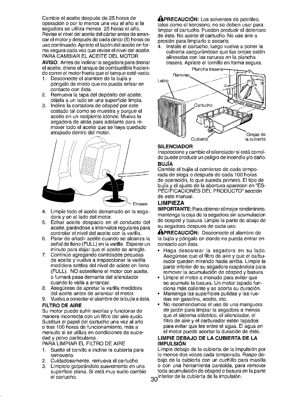
Cambieelaceitedespu_sde25horasde
operaci6nopotIomenosunavezala_osila
segadoraseutilizamenos25horaselaSo.
Revisee! nivet det aceite del carter antes de arran-
car el motor y despu_s de cada cinco (5) horas de
uso continuado. Apriete el tap6n del aceite en for-
ma segura cada vez que revise el nivel del aceite,
PARA CAMBIAR EL ACEITE DEL MOTOR
AVI80: Antes de inclinar la segadora para drenar
el aceite, drene el tanque de combustible hacien-
do cotter el motor hasta que el tanque est# vacio,
1. Desconecte el alambre de Ia bujia y
p6ngalo de modo que no pueda entrar en
contacto con _sta.
2, Remueva la tapa del dep6sito del aceite;
d_jela a un lado en una superficie limpia.
3. Incline la cortadora de c_sped pot este
costado tal como se muestra y purgue el
aceite en un recipiente id6neo. Mueva la
segadora de atr&s para adelante para re-
mover todo el aceite que se haya quedado
atrapado dentro deI motor.
ERvaSe
4. Limpie todo el aceite derramado en Ia sega-
dora yen el lado del motor.
5. Echar aceite despacio en el conducto del
aceite, parAndose a intervalos regulares para
controlar el nivel del aceite con la vadlla.
6. Parar de aSadir aceite cuando se alcanza la
seSal de Ileno (FULL) en la varilla. Esperar un
minuto para dejar que e! aceite se arregle.
7. ContinLie agregando cantidades pequeas
de aceite y vuelva a inspeccionar Ia varilla
medidora settles del nivel de aciete en Ileno
(FULL). NO sobrellene el motor con aceite,
o fumarA pesa demante del silenciador
cuando Io valla a arrancar.
8. Ase@rese de apretar la varilla medidora
del aceite antes de arrancar el motor.
9, Vuelva a conectar eI alambre de Iabujia a _sta.
FILTRO DE AIRE
Su motor puede sufrir aver[as y funcionar de
manera incorrecta con un filtro del aire sucio.
Sustituir el papel del cartucho una vez al aSo
o tras 100 horas de funcionamiento, m_s a
menudo si se utiliza en condiciones de sucie-
dad y polvo particulares.
PARA LIMPIAR EL FILTRO DE AIRE
1. Suelte el tornillo e incline Ia cubierta para
removerlo,
2, Cuidadosamente, remueva el cartucho,
3. Lfmpielo golpe_ndolo suavemente en una
superficie plan& SiestA muy sucio cambie
el cartucho.
_i, PRECAUCI6N: Los sotventes de petr61eo,
tales como el keroseno, no se deben usar para
Iimpiar el cartucho, Pueden producir el deterioro
de #ste. No aceite el cartucho, No use aire a
presi6n para timpiarlo o secarlo,
4. Instale el cartucho, luego vuelva a porter la
cubierta asegur&ndose que las orejas est_n
alineadas con las ranuras en la plancha
trasera. Apriete el tomillo en forma segura.
Ranuras
Labio
Ore}asde
Cubierta_ Iacubierta
81LENCIADOR
Inspeccione y cambie el silenciador si estA corroi-
do puede producir un peligro de incendio y/o daSo.
BUJJA
Cambie el bujia al comienzo de cada tempo-
rada de siega o despu6s de cada 100 horas
de operaci6n, Io que suceda primero. El tipo de
bujia y el ajuste de la abertura aparecen en "ES-
PECIFICACIONES DEL PRODUCTO _secci6n
de este manual,
LIMPIEZA
IMPORTANTE: Para obtener el mejor rendimineto,
mantenga la caja de la segadora sin acumulacion
de cesped y basura. Limpie Ia parte de abajo de
su segadora despues de cada uso.
_I=PRECAUCI6N: Desconecte el alambre de
Ia bujia y p6ngalo en donde no pueda entrar en
contacto con #sta.
• Haga descansar la segadora en su lado.
Aseg_rese que el filtro de aire y que e! carbu-
rador queden mirando hacia arriba. Limpie la
parte inferior de su segadora rasp_ndola para
remover la acumulaci6n de c_sped y basura.
• Limpie e! motor a menudo para evitar que
se acumule la basura. Un motor tapado fun-
ciona m_s caliente y se acorta su duraci6n,
• Mantenga las superficies pulidas y las rue-
das sin gasolina, aceite, etc.
• No recomendamos el uso de una manguera
de jardin para limpiar la segadora a menos
que el sistema eI_ctrico, el silenciador, el
filtro de aire y el carburador est_n tapados
para evitar que les entre el agua. El agua en
el motor puede acortar la duracibn de _ste.
LIMPIE DEBAJO DE LA CUBIERTA DE LA
IMPULSI(_N
Limpie debajo de la cubierta de la impulsi6n por
Io menos dos veces cada temporada. Raspe de-
bajo de la cubierta con un cuchillo para masilla
o con una herramienta parecida, para remover
toda acumulaci6n de c_sped o basura en la parte
inferior de la cubierta de la impulsi6n,
30
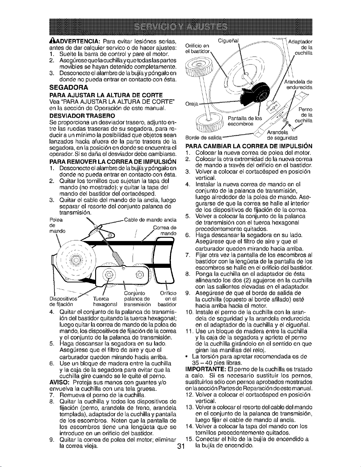
,_,DVERTENCIA: Para evitar lesi6nes serias,
antes de dar calquier service o de hacer ajustes:
1. Suelte la barra de control y pare el motor.
2. Aseg_rese quela cuchillayque todaslas partes
movibtes se hayan detenido completamente.
3. Desconecte el alambre de la bujia y p6ngalo en
donde no pueda entrar en contacto con _sta.
SEGADORA
PARA AJUSTAR LA ALTURA DE CORTE
Vea "PARA AJUSTAR LA ALTURA DE CORTE _
en la secci6n de Operaci6n de este manual.
DESVIADOR TRASERO
Se proporciona un desviador trasero, adjunto en-
tre las ruedas traseras de su segadora, para re-
duck a un minimo la posibilidad que objetos sean
lanzados hacia afuera de la parte trasera de la
segadora, en la posici6n en donde se encuentra el
operador. Si se daSa el desviador debe cambiarse.
PARA REMOVER LA CORREA DE IMPULSION
1. Desconecte eIalambre de la bujia y p6ngalo en
donde no pueda entrar en contacto con _sta.
2. Quitar los tomillos que sujetan Ia tapa del
mando (no mostrado); y quitar la tapa deI
mando del bastidor del cortac_sped.
3. Quitar el cable del mando de la ancla, luego
separar el resorte del conjunto palanca de
transmisi6n.
Potea
de
mando
Correa de
mando
Conjttnto Orificio
Tuerca palanea de en et
de fijaci6n hexagonal transmisi6n bastidor
4. Quitar el conjunto de la palanca de transmis-
i6n del bastidor quitando Ia tuerca hexagonal;
luego quitar la correa de mando de la polea de
mando, los dispositivos de fijaci6n de Ia correa
y el conjunto de la palanca de transmisi6n.
5. Haga descansar la segadora en su lade,
Asegdrese que el filtro de aire y que el
carburador queden mirando hacia arriba.
6. Use un bloque de madera entre Ia cuchilla
y la caja de la segadora para evitar que la
cuchilla gire cuando se le quite el pemo.
AVISO: Proteja sus manes con guantes y/o
envuetva la cuchilla con una tela gruesa.
7. Remueva el pemo de la cuchilla.
8. Quitar la cuchilla y todos los dispositivos de
fijaci6n (perno, arandela de freno, arandela
templada), adaptador de la cuchilla y pantalla
de los escombros. Noten que la pantalla de
los escombros tiene una leng0eta que se 14.
introduce en un orificio del bastidor.
9. Quitar la correa de polea del motor; eliminar 15.
la correa vieja. 31
CigueSat
Orifieio en de la
el bastidor, euehitla
_,randela de
endureeida
Oreja
Pemo
de la
euehitla
Arandela
Borde de salida, de seguridad
PARA CAMBIAR LA CORREA DE IMPULSION
1. Colocar la nueva correa de poiea del motor.
2. Colocar la otra extremidad de la nueva correa
de mando a trav_s del orificio en el bastidor,
3. Velvet a colocar el cortac_sped en posici6n
verticai,
4. Instalar Ia nueva correa de mando en el
conjunto de la palanca de transmisi6n,
luego alrededor de la polea de mando, Ase-
gurarse de que la correa se halle al interior
de los dispositivos de fijaci6n de la correa.
5. Volver a colocar la conjunto de la palanca
de transmisi6n con el tuerca hexagonal
precedentemente quitados,
6. Haga descansar la segadora en su lad&
Aseg_rese que el filtro de aire y que el
carburador queden mirando hacia arriba.
7. Fijar otra vez Ia pantalla de los escombros al
bastidor con la leng0eta de la pantalla de los
escombros se halle en el orificio del bastidor.
8. Ponga la cuchilla en el adaptador de _sta
alineando los dos (2) agujeros en la cuchitla
con las salientes etevadas en el adaptador.
9. Aseg_rese de que el borde de salida de
la cuchilla (opuesto al borde afilado) est6
hacia arriba hacia el motor,
10. Instale el pemo de la cuchilla con la aran-
dela de seguridad y la arandela endurecida
en el adaptador de Ia cuchilla y el cigueSal.
11. Use un bloque de madera entre la cuchitta
y la caja de la segadora y apriete el pemo
de la cuchitla gir_ndolo en el sentido en que
giran las manillas del reloj.
• La torsi6n para apretar recomendada es de
35 - 40 pies tibras,
IMPORTANTE: El perno de lacuchilla es tratado
a calo. Si es necesario sustituir los pemos,
sustituirlos s6to con pemos aprobados mostrados
en lasecci6n Partes de Reparaci6n de este manual.
12. Velvet a colocar el cortac_sped en posici6n
vertical.
13. Velvet a colocar el resorte del cable del mando
en el conjunto de la palanca de transmisi6n,
luego fijar el cable de mando al ancla.
Velvet a colocar la tapa det mando con los
tomillos precedentemente quitados.
Conectar el bile de la bujia de encendido a
la bujia de encendido.
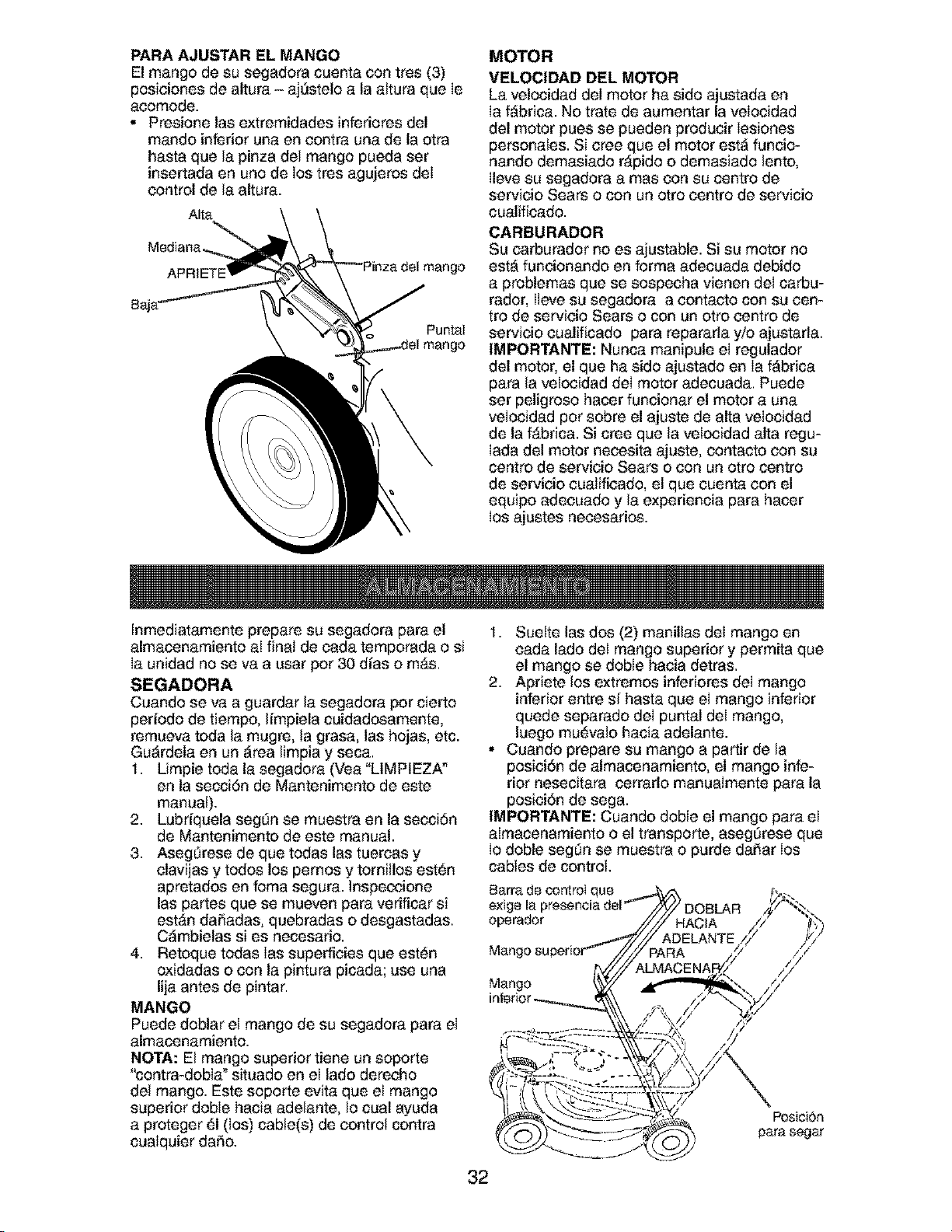
PARA AJUSTAR EL MANGO
El mango de su segadora cuenta con tres (3)
posiciones de altura - aj_stelo a la altura que Ie
aoomode.
• Presione las extremidades inferiores del
mando inferior una en contra una de la otra
hasta que la pinza del mango pueda ser
insertada en uno de los tres agujeros deI
control de la altura.
Alta
Puntal
MOTOR
VELOCIDAD DEL MOTOR
La velocidad del motor ha sido ajustada en
Ia fabric& No trate de aumentar la velocidad
del motor pues se pueden producir Iesiones
personales. Si cree que el motor est_ funcio-
nando demasiado r&pido o demasiado lento,
Ileve su segadora a mas con su centro de
servieio Sears o con un otro centro de servicio
cualificado.
CARBURADOR
Su carburador no es ajustable. Si su motor no
est_ funcionando en forma adecuada debido
a problemas que se sospecha vienen del carbu-
rador, Ileve su segadora a contacto con su een-
tro de servicio Sears o con un otto eentro de
servicio cualificado para repararla y/o ajustarla.
IMPORTANTE: Nunca manipule el regulador
del motor, el que ha sido ajustado en Ia fAbrica
para la velocidad deI motor adecuada. Puede
ser peligroso hacer funcionar el motor a una
velocidad pot sobre el ajuste de alta velocidad
de la fabric& Si cree que la velocidad alta regu-
Iada del motor necesita ajuste, eontacto con su
centro de servieio Sears o con un otro centro
de servicio cualifieado, el que euenta con el
equipo adecuado y la experiencia para hacer
los ajustes necesarios.
Inmediatamente prepare su segadora para el
almacenamiento aI final de cada temporada o si
Ia unidad no se va a usar pot 30 dias o m&s.
SEGADORA
Cuando se va a guardar la segadora por cierto
periodo de tiempo, limpiela cuidadosamente,
remueva toda la mugre, ta grasa, las hojas, etc.
Gu_rdela en un area limpia y seca.
1. Limpie toda la segadora (Vea "LIMPIEZA*
en la secci6n de Mantenimento de este
manual).
2. Lubriquela seg_n se muestra en la secci6n
de Mantenimento de este manual.
3. Aseg_rese de que todas las tuereas y
clavijas y todos los pernos y tornillos est_n
apretados en fema segura. Inspeccione
las partes que se mueven para verificar si
est_n daSadas, quebradas o desgastadas.
C_mbielas si es necesario.
4. Retoque todas Ias superficies que est_n
oxidadas o con la pintura picada; use una
lija antes de pintar.
MANGO
Puede doblar el mango de su segadora para el
almacenamiento.
NOTA: El mango superior tiene un soporte
"contra-dobla" situado en el lado dereeho
del mango. Este soporte evita que el mango
superior doble hacia adelante, Io cual ayuda
a proteger 61(los) cable(s) de control contra
cualquier daSo.
1. Suelte las dos (2) manillas del mango en
cada lado deI mango superior y permita que
el mango se doble hacia detras.
2. Apriete los extremos inferiores del mango
inferior entre si_basra que el mango inferior
quede separado deI puntal del mango,
luego mu_valo hacia adelante.
• Cuando prepare su mango a partir de la
posiciSn de almacenamiento, el mango infe-
rior nesecitara cerrarlo manualmente para la
posicibn de sega.
IMPORTANTE: Cuando doble el mango para el
almacenamiento o el transporte, asegSrese que
Io doble seg_n se muestra o purde daSar los
cables de control.
Barra de controI que
operador
Mang
Mango
_sioi6n
parasegar
32
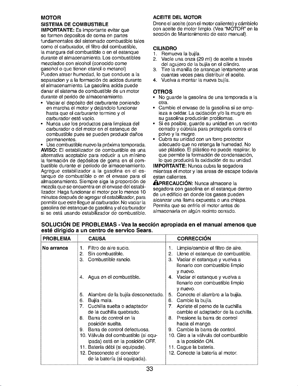
MOTOR
SISTEMA DE COMBUSTIBLE
IMPORTANTE: Es importante evitar que
se formen depositos de coma en partes
fundamentales del sistemade combustible tales
como el carburador, el fUtro del combustible,
Ia mangura del combustible o en el estanque
durante el almacenamiento. Los combustibles
mezclados con alcohol (conocido come
gasohoI o que tienen etanol o metanol)
Pueden atraer humedad, Io que conduce a la
separacion y a la formaciSn de acidos durante
el almacenamiento. La gasolina acida puede
danar el sistema de combustible de un motor
durante el perido de almacenamiento.
• Vaciar el dep6sito del carburante poniendo
en marcha el motor y dej,_ndolo funcionar
hasta que el carburante termine y el
carburador este vacio.
• Nunca use los productos para Iimpieza del
carburador odel motor en el estanque de
combustible pues se pueden producir daSos
permanentes.
• Use combustible nuevo la prSxima temporada.
AVISO: E! estabilizador de combustible es una
alternativa aceptable para reducir a un m[nimo
la formaciSn de depSsitos de goma en el com-
bustible durante el periodo de almacenamiento.
Agregue estabilizador a la gasolina en el es-
tanque de combustible o en el envase para el
almacenamiento. Siempre siga la proporciSn de
mezcla que se encuentra en el envase deI estabi-
Iizador. Haga funcionar el motor pot Io menos 10
minutos despu_s de agregar el estabilizador, para
permitir que este Ilegue al carburador. No vaciar la
gasolina det estanque de gasolina y el carburador
si se est,_ usando estabilizador de combustible.
ACEITE DEL MOTOR
Drene el aceke (con el motor caliente) y c_mbielo
con aceite de motor limpio. (Vea "MOTOR _en la
secciSn de Mantenimento de este manual).
CILINDRO
1. Remuevala bujla.
2. Vacie una onza (29 ml) de aceite a tray, s
de! agujero de la bujia en el cilindro.
3. Tire la manilla de arranque lentamente unas
cuantas veces para distdbuir el aceite.
4. Vuelva a montar Ia nueva bujia.
OTROS
• No guarde Ia gasoIina de una temporada a la
otra.
• Cambie el envase de la gasolina si se emp-
ieza a oxidar. La oxidacidn yio la mugre en
su gasolina producir_n problemas.
• Si es posible, guarde su unidad en un recinto
cerrado y c_brala para protegerla contra el
polvo y Ia mugre.
• Cubra su unidad con un forro protector
adecuado que no retenga la humedad. No
use pl,_stico. El pl,_stico no puede respirar, io
que permite la formacidn de condensacidn,
Io que producir,_ la oxidacidn de su unidad.
IMPORTANTE: Nunca cubra la segadora
mientras el motor y Ias areas de escape todavia
estan calientes.
_ILPRECAUCI6N: Nunca almacene la
segadora con gasolina en el estanque dentro
de un edificio en donde los gases pueden
alcanzar una llama expuesta o una chispa.
Permita que se enfde el motor antes de
almacenarla en algSn recinto cerrado.
SOLUCI()N DE PROBLEMAS -Yea la secci6n apropiada en el manual amenos que
este dirigido a un
PROBLEMA
centro de servico Sears.
CAUSA
No arranca 1. Filtro de aire sucio.
2. Sin combustible.
3. Combustible rancio,
4. Agua en el combustible.
5. Alambre de la bujia desconectado.
6. Bujia mala.
7. Cuchilla suelta o adaptador
de Ia cuchilla quebrado.
8. Barra de control en Ia
posiciSn suelta.
9. Barra de control defectuosa.
10. V,_lvula del combustible (si equ-
ipada) estA en Ia posici6n OFR
11. Bateria d_bi (si equipada).
12. Desconecte el conector
de la bateria (si equipada).
CORRECCI()N
1. Limpie/cambie el filtro de aire.
2. Llene el estanque de combustible.
3. Vaciar el estanque y vuelva a
Ilenarlo con combustible limpio
y nuevo,
4. Vaciar el estanque y vuelva a
Ilenarlo con combustible limpio
y nuevo,
5. Conecte el alambre a la bujia.
6. Cambie la bujia.
7. Apriete el pemo de la cuchilla
cambie el adaptador de la cuchilla.
8. Presione la barra de control
hacia el mango,
9. Cambie la barra de control.
10. Gire a la v&lvula del combustible
a la posici6n ON.
11, Cague la bateria.
12. Conecte la bateria aI motor.
33

SOLUCION DE PROBLEMAS -Vea la secci6n apropiada en el manual amenos que
este dirigido a un centro de servico Sears.
PROBLEMA
Falta de
fuerza
Mal corte-
disparejo
Vibracibn
excesiva
Cord6n
arrancador
dificil de tirar
Recogedor de
cesped no se
Ilena (si viene
equipado)
Dificil de
empujar
i
Perdida de
impulsibn
o retardase
de la
velocidad
CAUSA
1. Cuchitla desgastada, doblada
o suelta.
2. Altura de las ruedas dispareja.
3. Velocidad del motor lenta,
4. Acumulaci6n de c_sped, hojas o
basura debajo de Ia segadora.
5. Demasiado aceite en motor.
6. Velocidad de recorrido
demasiado r&pida.
1. Cuchitla desgastada, doblada
o suelta.
2. Altura de Ias ruedas dispareja.
3. Acumulaci6n de c_sped, hojas o
basura debajo de Ia segadora.
1. Cuchilla desgastada, doblada
o suelta.
2. CigueSal del motor doblado,
1. El freno deI volante del motor
est_ aplicado cuando se
suelta Ia barra de control,
2. CigueSal del motor doblado,
3. Adaptador de la cuchitla quebrado,
4. La cuchilla se arrastra en
el c_sped,
1. Altura de corte demasiado baja.
2. Levantamiento de Ia cuchilla
desgastado,
3. Recogedorsin ventilaci6n de aire.
1. E! c_sped est_ demasiado alto o la
altura de la rueda demasiado baja.
2. Parte trasera de la
caja/cuchilla de la segadora
arrastr&ndose en el c_sped.
3. Recogedor de c_sped
demasiado Ileno.
4. Posici6n de la altura del mango
no adecuada para usted,
1. Desgaste de la correa,
2. La correa estA fuera de la polea.
3. Cable de Ia impulsiSn usado o roto,
4. E! sistema de control del
mecanismo impulsor "sueltd'.
CORRECCION
1. Eleve la altura de corte.
2. Eleve la altura de corte.
3. Limpie/cambie el filtro de aire.
4. Limpie la parte inferior de Ia
caja de la segadora.
5. Revise el nivel del aceite.
6. Corte a una velocidad de
recorrido m_s Ienta.
1. Cambie la cuchitta. Apriete el perno
de la cuchilla,
2. Ajuste todas las ruedas a la misma
altura.
3. Limpie la parte inferior de Ia
caja de la segadora.
1. Cambie la cuchilla. Apriete el
perno de la cuchilla.
2. P6ngase en contacto con su centro
de servicio Sears o con un otro
centro de servicio cualificado,
1. Presione la barra de control
hacia el mango superior antes
de tirar el cord6n arrancador.
2. P6ngase en contacto con su centro
de servicio Sears o con un otro
centro de servicio cualificado,
3. Cambie el adaptador de Ia cuchilla.
4. Mueva la segadora a un lugar
en donde el c_sped ha sido
cortado o a una superficie firme
para hacer arrancar el motor.
1. Eleve la altura de corte.
2. Cambie las cuchittas.
3. Limpie el recogedor de c_sped,
1. Eleve la altura de corte.
2. Eleve la parte trasera de la caja de
la segadora (1) un lugar rods alto,
3. Vacie el recogedor de c_sped,
4. Ajuste la altura del mango de
modo que le acomode.
1. Reviseicambie cornea de impulsi6n.
2. Reviseivuelva a instalar la
3. Cambie el cable de la impulsiSn,
4. Ajuste el control del mecanismo
impulsor,
34
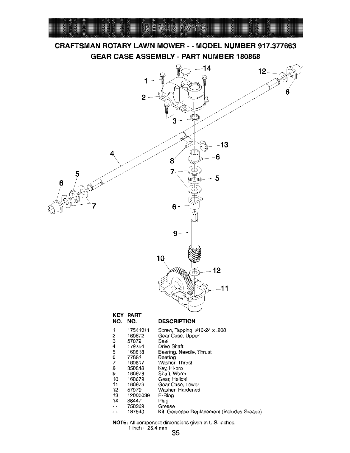
CRAFTSMAN ROTARY LAWN MOWER - - MODEL NUMBER 917.377663
GEAR CASE ASSEMBLY - PART NUMBER 180868
6
6
5
\
8\\
\
7
10
\
KEY PART
NO. NO. DESCRIPTION
1 17541011 Screw, Tapping #10-24 × .668
2 160672 Gear Case, Upper
3 57072 Seat
4 179754 Drive Shaft
5 160818 Bearing, Needte, Thrust
6 77881 Bearing
7 160817 Washer, Thrust
8 850848 Key, Hi-pro
9 160678 Shaft, Worm
10 160679 Gear, HelicaI
11 160673 Gear Case, Lower
12 57079 Washer, Hardened
13 12000039 E-Ring
14 86447 Plug
- - 750369 Grease
- - 187540 Kit, Oearcase Replacement (Includes Grease)
NOTE: AII component dimensions given in U.S. inches.
1 inch = 25.4 mm
35
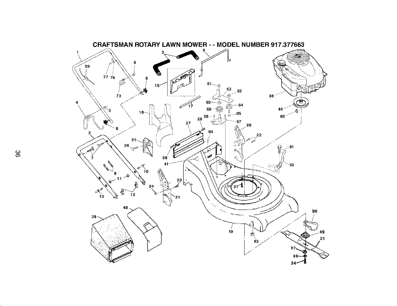
CRAFTSMAN ROTARY LAWN MOWER - - MODEL NUMBER 917,377663
5
//
/ j
77 76 8
61.-__-_
58
lO
39
31
34

CRAFTSMAN ROTARY LAWN MOWER - - MODEL NUMBER 917,377663
KEY PART
NO. NO.
I 182724
2 161t 05X479
3 182748
4 t 86079
5 132004
6 66426
7 131959
8 180833
9 182726
t0 161551
t t 73990500
t2 51793
t 6 t62085
17 179885
18 182778
19 186125
20 t 8102tX479
21 t 81020X479
22 t 50078
23 163183
24 73800500
25 161333
26 163409
27 t 6t 550
28 88652
29 t 82755
3I 175064
34 85I 084
37 t 50406
38 ---
39 t 86023
40 t 80026
4I 85463
KEY PART
DESCRIPTION NO. NO. DESCRIPTION
Handte, Upper with Grip 57 I79783X004 Bracket Assembly
Handle, Lower 58 57808 Screw
Grip, Foam 59 t 66042 Pulley, V-Groove
Rope Guide I Anti-Fold Bracket 60 t 66050 Spacer, Idter Arm
Nut, He×, with LookWasher Insert 1/4-20 61 145212 Ftange Nut
Wire, Tie 62 t 55552 Looknut
Bolt, Handle 5/I 6-I 8 x 1.75 63 1797I 9X004 Idler Arm
Knob, Handle 64 166043 Puliey, Idler
Bail, Wire 65 160829 Shoulder Bolt
Boit. Carriage 73 t 82003 Clip
Nut, Hex, with Lock Washer insert 5/t6-18 76 850733X004 Bracket, Upstop
Cotter, Hairpin 77 750634 Screw
Kit, Door Rear 84 54583 Screw
Seal, Door 85 187723 Key, Hi-Pro
Plug, Mulcher 86 184941 Puiiey
Kit, Housing 87 851074 Washer
Handie, Bracket Assembly, Left 88 850263 Washer, Look
Handte, Bracket Assembly, Right 89 t 84590 Btade Adapter
Screw, He× Washer Head 90 t 88245 Debris ShieId
Bott, Hex Head 5/I6-I8 x 5/6 gl 182227 Bolt
Nut, Hex, with Lock Washer insert 5/I 6-I 8 g2 182001 Beit Keeper
Baffie, Side 93 182228 Nut, Hex
Screw #t2 × 5/8 - - 161058 Warning Decai (Not Shown)
Skirt - - t 88044 Owner's Manual
Screw, Hinge t/4-20 × t 25
CabIe, MZR Available accessories not ir_cluded with lawn mower:
Blade 2I"
Bolt, Hex Head 7I 33623 Gas Can (2.5 Gallon Capacity)
Bolt, Engine 71 33500 FueI Stabilizer
Engine, Briggs & Stratton, Model Number 71 33000 SAE 30W Oil (20 Ourtce Bottle)
123KO2-O258-Et (See Breakdown) 7t 33086 Clipping Deflector
Grass Catcher Bag
Grass Catcher Frame NOTE: Att component dimensions given in U.S. inches.
Danger Decat t inch = 25,4 mm
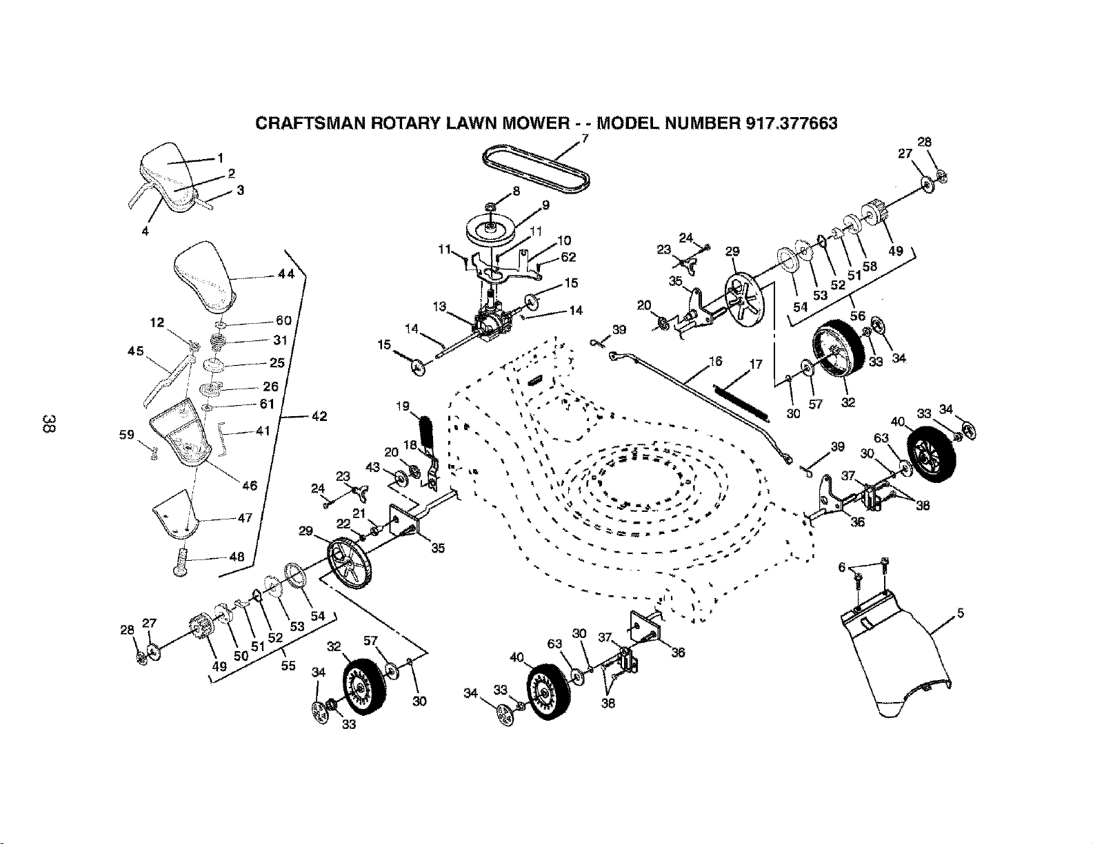
CRAFTSMAN ROTARY LAWN MOWER - - MODEL NUMBER 917,377663
2
3
4
15
11,.._ _-62
39
23 29
2O
28
27
49
Co
59
23
21
19
35
28
27
49
54
53
32
55 34
33
57
3O
63
3O
38
,5

CRAFTSMAN ROTARY LAWN MOWER - - MODEL NUMBER 917,377663
QD
KEY PART
NO. NO.
I 181232
2 181233
3 180612
4 182494
5 161537
6 750634
7 182212
8 132010
9 184749
t0 t6602tX004
tt 17541011
t2 181045
t3 180868
I4 145354
15 57079
16 161584
t7 161602
t8 t60477X004
t9 167650
20 12000022
2I 163365
22 169911
23 161tt8X004
24 57808
25 180604
26 180603
27 52160
28 12000058
29 180504
30 188152
3t 180607
32 188042
33 83923
KEY PART
DESCRIPTION NO. NO. DESCRIPTION
Decat Drive Control 34 I80626
Decal, Drive ControI Operation 35 t 60785 XOO4
CabIe, Drive 36 t 60786)(004
Decal, Drive Control Adjustment 37 t61463
Cover Drive 38 t 63409
Screw, Threaded, Roiled #t0-25x .50 39 700279
V-Beff 40 150348
Nut, Hex, Flangeiock, Zinc Plated 3/8-I6 41 181609
Putiey, Drive 42 181071
Belt Keeper Bracket 43 t 9572216
Screw, Hex Washer Heed #10-24 x .668 44 180601
Spring, Return, Lover 45 180982
Gear Case Aasembly (See Breakdown) 46 180602
Pin,Spring, Thrust 47 I81363X479
Washer, Hardened 48 181698
Rod, Connecting 49 175103
Spring, Extension 50 t 75t 02
Spring, SeIector 51 175098
Knob, Seteetor Spring 52 188291
E-Ring 7/8 53 175104
Bearing Support 54 175I 0I
Bearing, Ba_l 55 t 88293
Retainer, Drive Assembly.. Stamped 56 188292
Screw,Tapping, Hex Head t/4-20 x .75 57 67725
Puitey Spiit, Upper 58 175105
Puitey Spiit, Lower 59 t 80606
Washer 60 52160
E-Ring 7/I6 6I 57079
Cover, Dust, WheeI 62 54583
O-Ring 63 88348
Spring, Pulley Adjuster
WheeI 9 x 2
Nut, Hex, Ftangetoak 3/8-16
Hubcap, Mag Pta_num
Shaft Assembly, Rear
Shaft Assembly. Front
Retainer, Front Shaft
Screw #t2 x 5/8
Clip, Retainer
WheeI 8 x 2
Connector, Lever / Putiey
EZ Waik Drive ControI Assembly
Washer
Cover, Top, EZ Walk Drive Control
Lover, EZ Walk Drive Controt
Cover, Bottom EZ Walk Drive Control
Plate Trigger, EZ Walk Drive Control
Screw, Phillips Head #t0-5/8
Pinion, Gear
Retainer, Drive, RH
PawI
Spring, Torsion
Disc, Drive
Seat Friction
Pinion Assembly, RH
Pinion Assembly, LH
Washer, Flat tt2 x 1-1/2
Retainer, Drive, LH
Screw
Washer
Washer
Screw
Washer, Fiat 3t8
NOTE: Atl component dimeasions given in US inches
1 inch = 25,4 mm
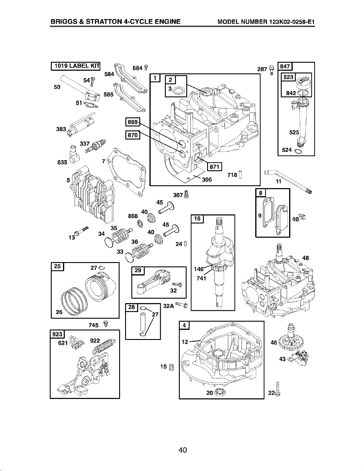
BRIGGS & STRATTON 4-CYCLE ENGINE MODEL NUMBER 123K02-0258-E1
I 1019 LABEL KI'I1
383_
635 _ 7(
5
684
718_
306
251 27 _=_
745
32
741
2o_
287
_ 84_zj
52511
524
4O
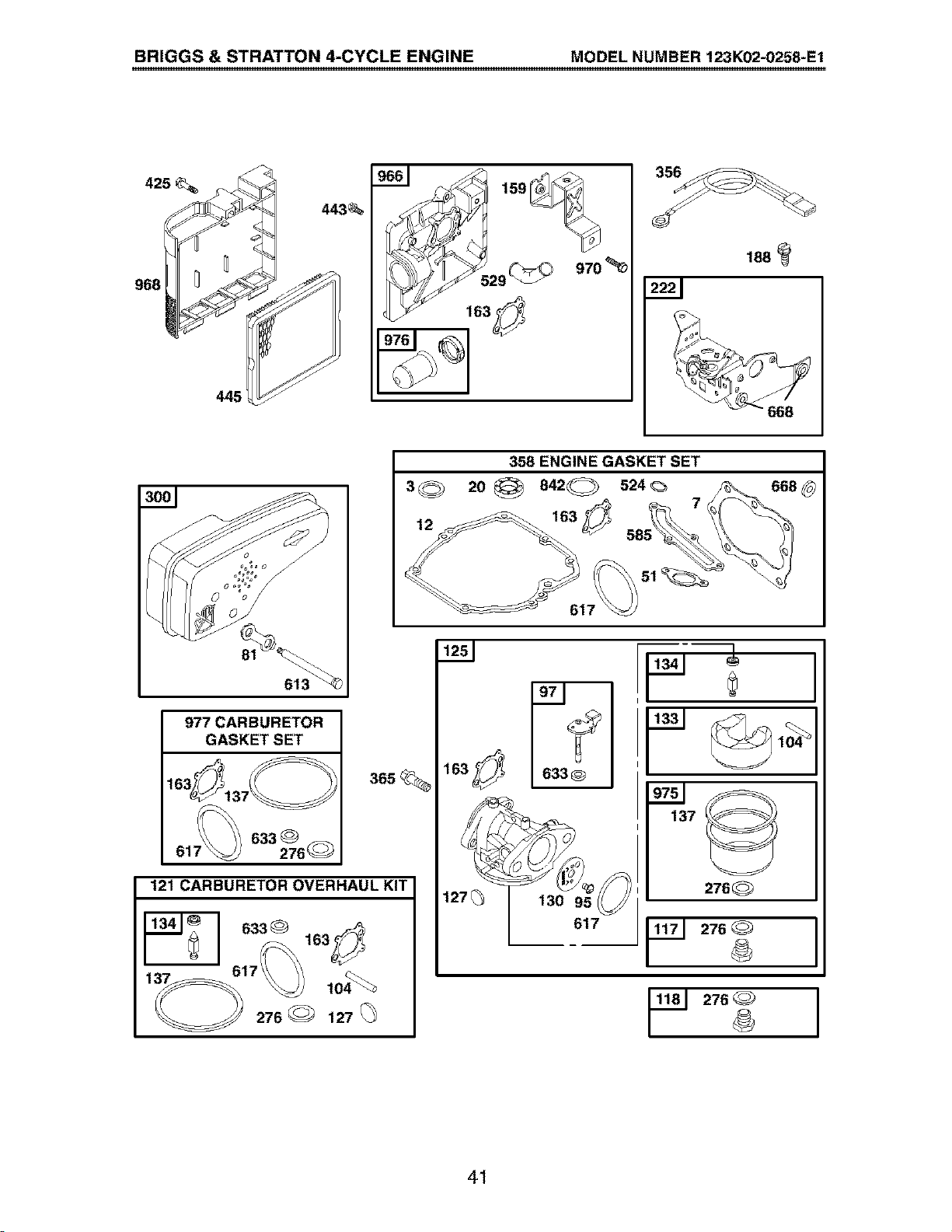
BRIGGS & STRATTON 4-CYCLE ENGINE MODEL NUMBER 123K02-0258-E1
425
968
445
443_
)66
2221
358 ENGINE GASKET SET
3© 20_ 842_ s24 6680
613
977 CARBURETOR
GASKET SET
z65
633 O --
61; 276_
121 CARBURETOR OVERHAUL KIT
8330
276 _ 127
127_
f
633®
130 95
617
1
137
276_
276 J
41
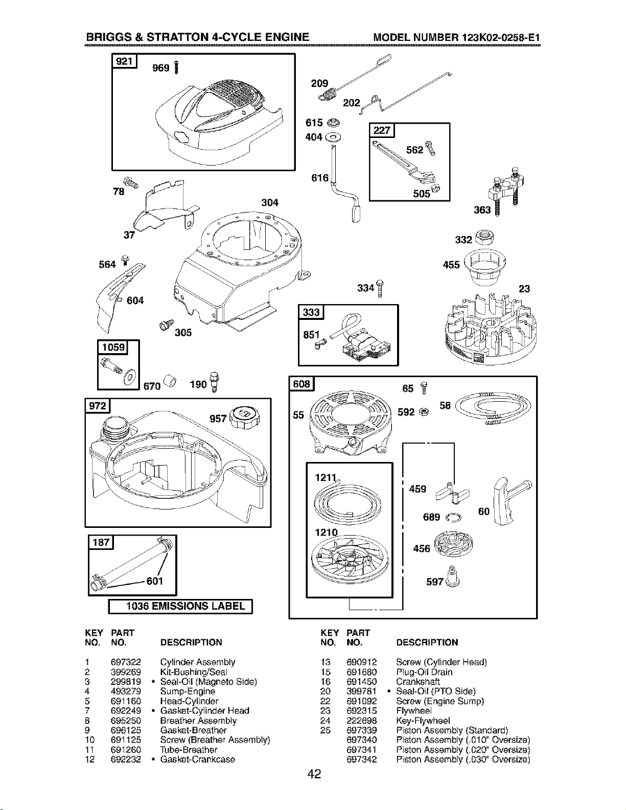
BRIGGS & STRATTON 4-CYCLE ENGINE MODEL NUMBER 123K02-0258-E1
969 !
304
615 O
404
562
505 8
332
_305
__Y
I
L 1036 EMISSIONS LABEL J
455
6s
58
5928
6O
689
456
597_
23
KEY PART
NO, NO, DESCRIPTION
KEY PART
NO, NO. DESCRIPTION
1 697322 Cylinder Assembly
2 399269 Kit-BushingfSea_
3 29981g • Seal-Oil (Magneto Side)
4 493279 Sump-Engine
5 69I 160 Head-Cylinder
7 692249 • Gasket-Cylnder Head
8 695250 Breather Assembly
9 696125 Gasket-Breather
10 69I 125 Screw (Breather Assembly)
1I 691260 Tube-Breather
12 692232 • Gasket-Crankcase
13 690912
15 691680
16 691450
20 399781
22 691092
23 692315
24 222698
25 697339
697340
697341
697342
42
Screw (Cylinder Head)
Plug-Oil Drain
Crankshaft
• Seal-Oil (PTO Side)
Screw (Engine Sump)
Flywheel
Key-Flywheel
Piston Assembly (Standard)
Piston Assembly (.010" Oversize)
Piston Assembly (.020" Oversize)
Piston Assembly (.O3O"Oversize)

BRIGGS & STRATTON 4-CYCLE ENGINE MODEL NUMBER 123K02-0258-E1
KEY PART
NO, NO, DESCRIPTION
KEY PART
NO, NO. DESCRIPTION
26 499425 Ring Set-Piston (Standard) 443 692523
499426 Ring Set-Piston (.010" Oversize) 445 491588
499427 Ring Set-Piston (.020" Oversize) 455 691219
499428 Ring Set-Piston (.030" Oversize) 456 692299
27 691866 Lock-Piston Pin 459 281505
28 499423 Pin-Piston 505 231082
29 499424 Rod-Connecting 523 495264
32 691664 Screw (Connecting Rod) 524 692296
32A 695759 Screw (Connecting Rod) 525 495265
33 262651 Valve-Exhaust 529 691923
34 262652 Valve-Intake 562 92613
35 691270 Spring-Valve (intake) 564 698589
36 691270 Spring-Valve (Exhaust) 584 692342
37 694086 Guard-Flywheel 585 691879
40 692194 Retainer-Valve 592 690800
43 691997 Slinger-Governor/Oil 597 691696
45 690548 Tappet-Valve 60I 95162
46 69I 449 Camshaft 604 698588
48 498829 Short Block (Replacement 608 497680
Engine 1251<02-0253) 613 691340
50 497465 Manifold-Intake 615 690340
5I 272199 • Gasketqntake 616 698801
54 691650 Screw (Intake Manifold) 617 270344
55 691421 Housing-Rewiod Starter 62I 692310
58 692259 Rope-Starter (Cut to Length) 633 691321
60 281434 Grip-Starter Rope 635 66538
65 690837 Screw (Rewind Starter) 668 493823
78 69I 108 Screw (Flywheel Guard) 670 692294
81 691740 Lock-Muffler Screw 684 690345
95 69I 636 Screw (Throttle Valve) 689 691855
97 696565 Shaft-Throttle 718 690959
104 691242 O Pin-F_oat Hinge 74I 691830
117 498978 Jet-Main (Standard) 745 691648
118 497466 Jet-Main (High Altitude) 842 691031
121 498260 Kit-Carburetor Overhaul 847 692017
125 498170 Carburetor 85I 493880
127 694468 O Plug-Welch 868 697338
130 696564 Valve-Throttle 869 691155
133 398187 FIoat-Carburetor 870 690380
134 398188 OValve-Needle/Seat 871 262001
137 693981 O_Gasket-Fioat BowI 63709
146 690979 Key-Timing 92I 698587
159 691753 Bracket-Air Cleaner Primer 922 692135
163 272653 ,O:l:Gasket-Air Cleaner 923 695891
187 691050 Line-Fuel (Cut to Required Length) 957 397974
188 693399 Screw (Controt Bracket) 966 496I 16
190 690940 Screw (Fuel Tank) 968 692298
202 691829 Link-Mechanical Governor 969 691138
209 690319 Spring-Governor 970 691669
222 692467 Bracket-Control 972 495224
227 690783 ControI Lever-Governor 975 493640
276 271716 O_Seating Washer 976 694395
287 690940 Screw (Dipstick Tube) 977 498261
300 692038 Muffler 1019 494256
304 695892 Housing-Blower 1036 697456
305 691108 Serew(BlowerHcosing) 1059 692311
306 690450 Shield-Cylinder 1210 498144
307 690345 Screw (Cyiioder Shield) 1211 498144
332 690662 Nut (Flywheel)
333 802574 Armature-Magneto
334 69I 06I Screw (Armature Magneto)
337 802592 Plug-Spark
356 692390 Wire-Stop
358 497316 Engine Gasket Set
363 19069 Fiywheel Pulter
365 692524 Screw (Carburetor)
383 89838 Wrench-Spark Ptug
404 690272 Washer (Governor Crank)
425 690670 Screw (Air CIeaner Cover)
Screw (Air CIeaner Primer Base)
Filter-Air CIeaner Cartridge
Cup-Flywheel
P_ate-Pawl Friction
Pawi-Ratehet
Nut (Governor Control Lever)
Dipstick
• Seal-Dipstick Tube
Tube-Dipstick
Grommet
Bolt (Governor Control Lever)
Screw (Control Cover)
Cover-Breather Passage
• Gasket-Breather Passage
Nut (Rewind Starter)
Screw (PawI Friction Plate)
Clamp-Hose
Cover-C_ntrol
Starter-Rewiod
Screw (Muffler)
Retainer-Governor Shaft
Crank-Governor
•Q¢SeaI-O Ring (Intake Manifold)
Switch-Stop
O:l:SeaI-Throttle Shaft
Boot-Spark Plug
• Spacer (Includes 2)
Spacer-Fuel Tank
Screw (Breather Passage Cover)
Spring-Friction
Pin-Locating
Gear-Timing
Screw (Brake)
• SeaI-O Ring (DipstickTube)
Assembly- Dipstick/Tu be
Terminal-Spark PIug
Seal-Valve
Seat-Valve (Intake)
Seat-Valve (Exhaust)
Bushing-Guide (Exhaust)
Bushing-Guide (Intake)
Cover-Blower Housing
Spring-Brake
Brake
Cap-Fuel Tank
Base-Air Cleaner Primer
Cover-Air Cteaner
Screw (Blower Housing Cover)
Screw (Air CIeaner Primer Bracket)
Tank-Fuel
BowFF_oat
Primer-Carburetor
Set-Carburetor Gasket
Kit-Label
Label-Emissions
Kit-ScrewAt_asher
Assembly- Pulley/Spring (Putley)
Assembly- Pulley/Spring (Spring)
RPM Settings: Low: 1900-2100; High:3000-3200
included in Engine Gasket Set, Key No. 358
O included in Carburetor Overhaut Kit, Key No. 121
included in Carburetor Gasket Set, Key No. 977
NOTE: All component dimensions given in U.S. inches
1 inch = 25,4 mm
43

Your Home
For repair - in your home - of all major brand appliances,
lawn and garden equipment, or heating and cooling systems,
no matter who made it, no matter who sold it!
For the replacement parts, accessories and
owner's manuals that you need to do-it-yourself.
For Sears professional installation of home appliances
and items like garage door openers and water heaters.
1-800-4-MY-HOME ® Anytime, day or night
(1-800-469-4663) (U.S.A. and Canada)
www,sears,com www,sears,ca
Our Home
For repair of carry-in products like vacuums, lawn equipment,
and electronics, call or go on-line for the nearest
Sears Parts and Repair Center.
1-800-488-1222 Anytime, day or night (U.S.A. only)
www.sears, com
To purchase a protection agreement (U.S.A.)
or maintenance agreement (Canada) on a product serviced by Sears:
1-800-827-6655 (U.S.A) 1-800-361-6665 (Canada)
Para pedir servicio de reparaciSn
a domicilio, y para ordenar piezas:
1-888.SU-HOGAR sm
(1-888-784-6427)
Au Canada pour service en franc_,ais:
1-800-LE-FOYER Mc
(1_7)
www.sears.ca
, E/ARS
© Sears,RoebuckandCo.
® Registered Trademark / -r_Trademark / s_ Service Mark ol Sears, Roebuck and Co.
® Marca Registreda / _MMarca de FAbrica / smMarca de Servicio de Sears, Roebuck and Co.
mcMarque de commerce/MD Marque d6pos_e de Sears, Roebuck and Co.
P
188044 Rev. 2 09.03.03 BY Printed in U.S.A.