
User Guide
For Soundcraft Signature 10, 12 & 12MTK
10, 12, 12MTK User Manual
INFORMATION
INFORMATION
INFORMATION
IMPORTANT
Please read this manual carefully before using your mixer
for the rst time.
This equipment complies with the EMC directive 2004/108/EC and LVD 2006/95/EC.
This product is approved to safety standards:
IEC 60065:2005 (Seventh Edition) +A1:2005
EN60065:2006 +A1:2006 +A1:2008
UL60065 2012 7th Edition
CAN/CSA-E60065-03 + A1: 2006
And EMC standards
EN55103-1: 2009 (E2)
EN55103-2: 2009 (E2)
Warning: Any modication or changes made to this device, unless explicitly approved by Harman, will
invalidate the authorisation of this device. Operation of an unauthorised device is prohibited under Section
302 of the Communications act of 1934, as amended, and Subpart 1 of Part 2 of Chapter 47 of the Code of
Federal Regulations.
NOTE: This equipment has been tested and found to comply with the limits for a Class B digital device, pursuant to
Part 15 of the FCC Rules. These limits are designed to provide reasonable protection against harmful interference in
a residential installation. This equipment generates, uses and can radiate radio frequency energy and, if not installed
and used in accordance with the instructions, may cause harmful interference to radio communications. However,
there is no guarantee that interference will not occur in a particular installation. If this equipment does cause harmful
interference to radio or television reception, which can be determined by turning the equipment off and on, the user is
encouraged to try to correct the interference by one or more of the following measures:
* Reorient or relocate the receiving antenna.
* Increase the separation between the equipment and the receiver.
* Connect the equipment into an outlet on a circuit different from that to which the receiver is connected.
* Consult the dealer or an experienced radio/TV technician for help.
For further details contact: Harman International Industries Ltd, Cranbourne House, Cranbourne Road, Potters Bar,
Hertfordshire EN6 3JN, UK. Telephone +44 (0)1707 665000 Fax: +44 (0)1707 660742 email: [email protected]
© Harman International Industries Ltd. 2014. All rights reserved.
Parts of the design of this product may be protected by worldwide patents.
Part No. 5056808
Rev 1.1
E&OE September 2014
Soundcraft is a trading division of Harman International Industries Ltd. Information in this manual is subject to change
without notice and does not represent a commitment on the part of the vendor. Soundcraft shall not be liable for any
loss or damage whatsoever arising from the use of information or any error contained in this manual. No part of this
manual may be reproduced, stored in a retrieval system, or transmitted, in any form or by any means, electronic,
electrical, mechanical, optical, chemical, including photocopying and recording, for any purpose without the express
written permission of Soundcraft.
Harman International Industries Limited
Cranborne House, Cranborne Road, Potters Bar, Hertfordshire, EN6 3JN, UK
Tel: +44 (0)1707 665000
Fax: +44 (0)1707 660742
http://www.soundcraft.com

CONTENTS
CONTENTS
CONTENTS
1.0 AN INTRODUCTION TO SIGNATURE
1.0.1 The Signature Legacy
1.0.2 Sapphyre Asymmetric EQ
1.1: Safety
1.2: Warranty
1.3:Specications
2.0: GETTING STARTED
2.1: Introduction To Consoles
2.2: Parts Of The Console
3.0: INPUTS AND OUTPUTS
3.1: Introduction to I/O
3.2: Console Inputs
3.3: Console Outputs
3.4: Other I/O
4.0: CONSOLE ROUTING
4.1: Mono Input Channel
4.1: Stereo Input Channel
4.3: FX Return Channel
4.4: Aux Master Output
4.5: Group Master Output
4.6: Master Stereo Output
5.0: CHANNEL CONTROLS
5.1: Input Controls
5.1.1: Mono Input Controls
5.1.2: Stereo Input Controls
5.1.3: FX Return Controls
5.2: Aux Master Controls
5.3: Group Master Controls
5.4: Master Stereo Controls
6.0: SOLO AND MONITORING
7.0: USB OPERATION
7.1: Signature 10, 12 USB
7.2: Signature 12MTK USB
8.0: LEXICON FX
8.1: FX Control
8.2: Reverbs
8.3: Delays And Modulation
APPENDIX 01: NO SOUND?
A Troubleshooting Guide.
For clarity, this manual uses section references rather than page numbers. In some instances, one section reference
may extend to several pages.
10, 12, 12MTK User Manual

10, 12, 12MTK User Manual
1.0: INTRODUCTION
INTRODUCTION TO SIGNATURE
1.0: INTRODUCTION TO SIGNATURE
Drawing on over 40 years experience in live sound mixing, the Signature Series combines a superb
analogue control surface with the unrivalled British sound of Soundcraft in a powerful, compact,
professionally spec’d mixer.
Built tough for trouble-free performance night-after-night, Signature Series mixers deliver great
sounding results thanks to high-grade Ghost® preamps, the most musical EQ in the business, pristine
Lexicon® effects and powerful dbx® dynamics - all designed to let you discover your Signature sound.
• Soundcraft® Ghost Mic Preamps
Class-leading performance, with high headroom, wide dynamic
range and superb signal to noise ratio.
• Soundcraft® Sapphyre British EQ
Famed for its musical sound and unmistakable ‘British’ quality
• Soundcraft® GB audio routing
Flexible pre/post switching on each Aux and subgroups with
powerful routing and switching options as well as dedicated
outputs.
• dbx® Limiters
High performance, high-ratio Compressors on selected input
channels.
• Hi-Z instrument inputs
Switchable input stage, optimised for acoustic guitars, electric
guitars, and basses.
• Award-winning Lexicon® effects
Studio-grade Reverbs, Delays, Choruses and Modulations,
designed to add a truly professional edge to your productions.
• USB Digital Audio
USB digital I/O for direct connection to Digital Audio Worksta-
tions and digital systems. Signature MTK version adds Multi-
Track functionality.
• Playback Channel Functions
‘Interval Mute’ fast switching of playback channel to main out-
puts, plus independent Pre/Post Aux switching.
• Built tough for the long haul
Robust metal construction and premium-quality components:
Built to withstand the rigours of extensive use.

10, 12, 12MTK User Manual
1.0.1: SIGNATURE LEGACY
SIGNATURE LEGACY
1.0.1: SIGNATURE LEGACY
The Signature Series consoles bring musicality, creativity, and technical excellence together, thanks
not only to new technology and ideas, but also to a 40-year legacy of producing outstanding
performance tools. This console incorporate classic analogue designs, approved by Engineers.
Ghost® pre-amps
The Soundcraft Ghost console’s ProMic
mic pre-amp is known for it’s ultra-low
noise and high headroom, making high
gain settings possible, without
compromising signal integrity.
Sapphyre British EQ
The Soundcraft Sapphyre console
Asymmetric EQ makes both creative and
functional tonal shaping of your signal
simple and intuitive. The EQ behaves
differently in cut and boost, making tonal
adjustments musical, and focusing cuts
where they are needed. See section 1.0.2
for more detail.
GB Routing
The GB Console legacy is in Signature’s
signal routing. There is pre/post switching
forallauxbusses,plusexibleroutingand
dedicated outputs for sub-groups.
See section 4 for more detail.

10, 12, 12MTK User Manual
1.0.2: SAPPHYRE EQ
SAPPHYRE EQ
1.0.2: SAPPHYRE EQ
Soundcraft Sapphyre Asymmetric EQ
TheSoundcraftSignatureconsoleusesaspecialAsymmetricEQrstdevelopedfortherenowned
Soundcraft Sapphyre console. This EQ makes both creative and functional tonal shaping of your signal
simple and intuitive - an EQ that works the way music does.
The shelving bands of the EQ (LF and HF) use a slight boost at the EQ’s frequency when cutting,
and a slight cut when boosting.
For low frequencies, a slight cut when boosting prevents muddiness in he signal, while a slight boost when
cutting enables you to clean up the low end without losing precious ‘punch’ and ‘body’ of the signal. For the
HF shelf, a slight cut when boosting prevents harsh resonance at the EQ’s frequency, and a slight boost
before a cut can help maintain brightness while reducing HF.
The mid-band (bell-shape) has a wide bandwidth (low Q) when boosting, and a narrower bandwidth
(high Q) when cutting.
The wide boost prevents prevent harsh resonances and tonal-changes that allow for a more pleasing and
musical EQ boost. The Narrow cut focuses on problematic frequencies, for getting rid of resonances, rings,
hums, and preventing feedback. If this was too wide you could remove too much ‘body’, creating a thin
sound.
10, 12, 12MTK User Manual
1.1: SAFETY
INTRODUCTION > SAFETY
1.1: INTRODUCTION > SAFETY
THIS UNIT MUST BE EARTHED
Under no circumstances should the mains earth be disconnected from the mains lead.
The wires in the mains lead are coloured in accordance with the following code:
Earth: Green and Yellow (Green/Yellow - US)
Neutral: Blue (White - US)
Live (Hot): Brown (Black - US)
As the colours of the wires in the mains lead may not correspond with the coloured markings identifying the terminals
in your plug, proceed as follows:
The wire which is coloured Green and Yellow must be connected to the terminal in the plug which is marked with the
letter E or by the earth symbol.
The wire which is coloured Blue must be connected to the terminal in the plug which is marked with the letter N.
The wire which is coloured Brown must be connected to the terminal in the plug which is marked with the letter L.
Ensure that these colour codings are followed carefully in the event of the plug being changed.
This unit is capable of operating over a range of mains voltages as marked on the rear panel.
The internal power supply unit contains no user serviceable parts. Refer all servicing to a qualied service
engineer, through the appropriate Soundcraft dealer.
SAFETY NOTICES
For your own safety and to avoid invalidation of the warranty
please read this section carefully.
Important Symbols
Warnings
Alerts the user to the presence of uninsulated
‘dangerous voltage’ within the product’s
enclosurethatmaybeofinsufcientmagnitude
to constitute a risk of electric shock to persons.
Cautions
Alerts the user to the presence of important
operating and maintenance (servicing)
instructions in the literature accompanying
the appliance.
10, 12, 12MTK User Manual
1.1: SAFETY
INTRODUCTION > SAFETY
1.1: INTRODUCTION > SAFETY
WARNINGS
• Read these instructions.
• Keep these instructions.
• Heed all warnings.
• Follow all instructions.
• Clean the apparatus only with a dry cloth.
• Do not install near any heat sources such as radiators, heat resistors, stoves, or other apparatus
(includingampliers)thatproduceheat.
• Do not block any ventilation openings. Install in accordance with the manufacturer’s instructions.
• Do not use this apparatus near water.
• Do not defeat the safety purpose of the polarized or grounding type plug. A polarized plug has two
blades with one wider than the other. A grounding type plug has two blades and a third grounding
prong. The wide blade or the third prong are provided for your safety. When the provided plug does not
tintoyouroutlet,consultanelectricianforreplacementoftheobsoleteoutlet.
• Protect the power cord from being walked on or pinched particularly at plugs, convenience
receptacles and the point where they exit from the apparatus.
• Onlyuseattachments/accessoriesspeciedbythemanufacturer.
• Unplug this apparatus during lightning storms or when unused for long periods of time.
• Referallservicingtoqualiedservicepersonnel.Servicingisrequiredwhentheapparatushasbeen
damaged in any way such as power-supply cord or plug is damaged, liquid has been spilled or objects
have fallen into the apparatus, the apparatus has been exposed to rain or moisture, does not operate
normally, or has been dropped.
• Useonlywiththecart,stand,tripod,bracket,ortablespeciedbythemanufacturer,orsoldwiththe
apparatus. When the cart is used, use caution when moving the cart/apparatus combination to avoid
injury from tip-over.
• Nonakedamesources,suchaslightedcandlesorcigarettesetc.,shouldbeplacedonthe
apparatus.
• No user serviceable parts.Referallservicingtoaqualiedserviceengineer,throughthe
appropriate Soundcraft dealer.
• It is recommended that all maintenance and service on the product should be
carried out by Soundcraft or its authorised agents. Soundcraft cannot accept any
liability whatsoever for any loss or damage caused by service, maintenance or repair
by unauthorised personnel.
• WARNING: To reduce the risk of re or electric shock, do not expose this
apparatus to rain or moisture. Do not expose the apparatus to dripping or splashing
and do not place objects lled with liquids, such as vases, on the apparatus. No
naked ame sources, such as lighted candles, should be placed on the apparatus.
• Ventilation should not be impeded by covering the ventilation openings with items
such as newspapers, table cloths, curtains etc.
10, 12, 12MTK User Manual
1.1: SAFETY
INTRODUCTION > SAFETY
1.1: INTRODUCTION > SAFETY
WARNINGS
ADVICE FOR THOSE WHO PUSH THE BOUNDARIES
Although your new console will not output any sound until you feed it signals, it has the
capabilitytoproducesoundswhich,whenmonitoredthroughanamplierorheadphones,
can damage hearing over time.
Please take care when working with your audio — if you are manipulating controls which
you don’t understand (which we all do when we are learning), make sure your monitors are turned
down. Remember that your ears are the most important tool of your trade, look after them, and they will
look after you.
Mostimportantly—don’tbeafraidtoexperimenttondouthoweachparameteraffectsthesound—
this will extend your creativity and help.
NOTE: The packaging, in which your console arrived, forms part of the product and must
be retained for future use.
NOTE: This equipment has been tested and found to comply with the limits for a Class B
digital device, pursuant to Part 15 of the FCC Rules. These limits are designed to provide
reasonable protection against harmful interference when the equipment is operated in a
commercial environment. This equipment generates, uses and can radiate radio frequency
energy and, if not installed and used in accordance with the instruction manual, may cause
harmful interference to radio communications. Operation of this equipment in a residential
area is likely to cause harmful interference in which case the user will be required to correct the inter-
ference at his own expense.
This Class B digital apparatus meets the requirements of the Canadian Interference-Causing
Equipment Regulations.
Cet appareil numérique de la Classe B respecte toutes les exigences du Règlement sur le matériel
brouilleur du Canada.

10, 12, 12MTK User Manual
1.2: WARRANTY
INTRODUCTION > SAFETY
1.2: INTRODUCTION > WARRANTY
WARRANTY
1 Soundcraft is a trading division of Harman International Industries Ltd.
EndUsermeansthepersonwhorstputstheequipmentintoregularoperation.
Dealer means the person other than Soundcraft (if any) from whom the End User purchased the Equipment, pro-
vided such a person is authorised for this purpose by Soundcraft or its accredited Distributor.
Equipment means the equipment supplied with this manual.
2 If within the period of twelve months from the date of delivery of the Equipment to the End User it shall prove
defective by reason only of faulty materials and/or workmanship to such an extent that the effectiveness and/or
usability thereof is materially affected the Equipment or the defective component should be returned to the Dealer
or to Soundcraft and subject to the following conditions the Dealer or Soundcraft will repair or replace the defec-
tive components. Any components replaced will become the property of Soundcraft.
3 Any Equipment or component returned will be at the risk of the End User whilst in transit (both to and from the
Dealer or Soundcraft) and postage must be prepaid.
4 This warranty shall only be available if:
a) The Equipment has been properly installed in accordance with instructions contained in Soundcraft’s manual.
b)TheEndUserhasnotiedSoundcraftortheDealerwithin14daysofthedefectappearing;and
c) No persons other than authorised representatives of Soundcraft or the Dealer have effected any replacement
ofpartsmaintenanceadjustmentsorrepairstotheEquipment;and
d) The End User has used the Equipment only for such purposes as Soundcraft recommends, with only such
operatingsuppliesasmeetSoundcraft’sspecicationsandotherwiseinallrespectsinaccordanceSoundcraft’s
recommendations.
5 Defects arising as a result of the following are not covered by this Warranty: faulty or negligent handling, chem-
icalorelectro-chemicalorelectricalinuences,accidentaldamage,ActsofGod,neglect,deciencyinelectrical
power, air-conditioning or humidity control.
6.ThebenetofthisWarrantymaynotbeassignedbytheEndUser.
7. End Users who are consumers should note their rights under this Warranty are in addition to and do not affect
any other rights to which they may be entitled against the seller of the Equipment.

10, 12, 12MTK User Manual
1.3: SPECIFICATIONS
INTRODUCTION > SPECIFICATIONS
1.3: INTRODUCTION > SPECIFICATIONS
TYPICAL SPECIFICATIONS
• Frequency Response
- Mic / Line In to any Output: +/-1.5dB, 20Hz-20kHz
• T.H.D.
- Mono Mic Sensitivity -30dBu, Input level -16dBu,
+14dBu @ Mix output: < 0.002% @ 1kHz
- Stereo Mic Sensitivity -30dBu, Input level -16dBu,
+14dBu @ Mix output: < 0.007% @ 1kHz
• Noise
- Mono Mic Input E.I.N. (max gain): <-126dBu
(150Ωsource)
- Stereo Mic Input E.I.N. (max gain): <-124dBu
(150Ωsource)
• Crosstalk (@ 1kHz)
- Channel Mute: >-90dB
- Fader Cut-off (rel +10 mark): >-90dB
- Aux Send Pots Offness: >-82dB
EQ (Mono inputs)
- HF: 12kHz, +/-15dB
- MF (swept): 140Hz – 3kHz, +/-15dB
- LF: .60Hz, +/-15dB
EQ (Stereo inputs)
- HF: 12kHz, +/-15dB
- MF: 1kHz, +/-15dB
- LF: 60Hz, +/-15dB
Power Consumption
- Signature 10: <50VA
- Signature 12: <60VA
- Signature 12MTK: <70VA
Operating Conditions
- Temperature Range: 5°C to 40°C
Input & Output Levels
- Mic Input: +12.5dBu max
- Line Input: >+26dBu max
- Stereo Inputs: >+26dBu max
- Mix Output: +21.5dBu max
-Headphones(@150Ω):300mW
Input & Output Impedances
-MicInput:1.2kΩ
-Hi-ZInput:968kΩ
-LineInput:10kΩ
-StereoInput:21.5kΩ
-Outputs:150Ω(balanced),75Ω(unbalanced)
USB Audio (10, 12)
- Inputs/Outputs: 2-in, 2-out
- Bit Depth: 16-bit, 24-bit
- Sampling rate: 44.1kHz / 48kHz / 88.2kHz / 96kHz /
176.4kHz / 192kHz
Multi-channel USB Audio (12MTK)
- Inputs/Outputs: 14-in, 12-out
- Bit Depth: 16-bit, 24-bit
- Sampling rate: 44.1kHz / 48kHz
Net Weight
- Signature 10: 4.96kg
- Signature 12: 5.66kg
- Signature 12MTK: 5.86kg
Unit Dimensions (W × H × D)
- Signature 10: 490mm x 380mm x 210mm
- Signature 12: 490mm x 455mm x 210mm
- Signature 12MTK: 490mm x 455mm x 210mm
10, 12, 12MTK User Manual
2.0: GETTING STARTED
GETTING STARTED - AN INTRODUCTION TO THIS MANUAL
2.0: INTRODUCTION TO THIS MANUAL
Anyone with minimal audio experience should be able to operate the Soundcraft Signature console
without reading too much of this manual, though we do recommend you take the time to go through it.
An excellent place to start would be the feature list on the introductory page (section 1.0), which will
familiarise you with all of the main possibilities, facilities, and functions.
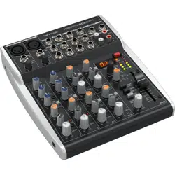
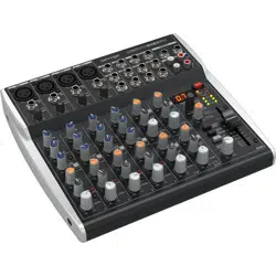
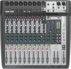
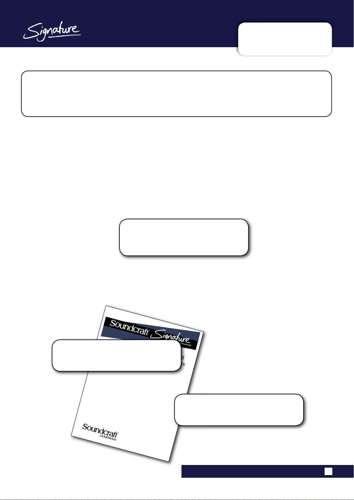
Please note: Most of the illustrations in this
manual are based on the Signature 12 console.
Where there are differences between operation
of Signature 10, 12, and 12 MTK, it is noted in
the relevant section.
User Guide
For Soundcraft Signature 10, 12 & 12MTK
PDF
If you’re reading the PDF version of the manual,
you can use the thumbnail view and links from
the Contents page to navigate quickly.
For clarity, this manual uses section references
rather than page numbers. In some instances,
one section reference may extend to several
pages.

10, 12, 12MTK User Manual
2.1: CONSOLE INTRO
GETTING STARTED > INTRODUCTION TO MIXING CONSOLES
2.1: INTRODUCTION TO CONSOLES
The main function of a mixing console is to combine different audio inputs and independently adjust the levels
of those contributions to the mix. With this very basic functionality you can control and balance any kind of audio
from a one-man-band to an orchestra.
Most mixers however (including the Signature Series) offer far more than that. A variety of features allow the
operator to shape the mix, and use routing options to provide the additional conveniences used in audio mixing
applications, such as external effects sends, stage monitoring outputs, independent headphone monitoring, and
digital inputs and outputs.
Mix Faders
Faders make it easy to see and adjust relative levels. They allow you to visualise the mix.
Input Choice
All different microphones and instruments are catered for with mic, line, and Hi-Z input types / selections,
including 48V phantom power for powered (condenser / capacitor) microphones. The gain control allows you to
optimise the input level.
Equalisation
Examplesincludethehighpasslteronaninputtoreduceunwantedlowfrequencies,orthethree-bandEQ
(Equaliser) used for tonal ‘shaping’ of the source.
Dynamic Processing
This is audio processing that affects amplitude (volume). The Signature console includes a Limiter on selected
channels, which will prevent the input signal going too high, which would in turn cause distortion.
Output options
As well as mixing all the input (source) channel into one Master Stereo output, you can send particular
channels into additional group outputs, or create several different aux (auxiliary) mixes of all channels to send
to an FX (Effects) processor or stage monitor, for example. The headphone output allows the operator to listen
to the whole Main Mix, or to a selection of channels via the Solo System.
Solo / Monitor System
The solo system allows you to listen only to particular channels or busses through the headphones output, so
you can focus on a particular source without changing the mix.
Internal FX
FX (Effects) processing such as reverb, delay, chorus, phasing, and so on can be incorporated into a mixing
console so that you don’t have to invest in ‘outboard’ equipment or use up valuable physical inputs and outputs.
The Signature’s Lexicon FX processing can be applied in a controlled manner by using the Auxiliary 3/FX mix
and the dedicated stereo FX return channel.
Digital inputs and outputs.
Digital I/O is necessary to work with digital audio systems and computer-based Digital Audio Workstations.
The Signature series uses a USB interface for either 2-channel input/output (main or Aux 1-2 output), or for
multitrack input and output (MTK versions) with the USB inputs able to individually replace the input channel
sourceforaexible‘tapereturn’path.Forexample,theMTKfunctionalitycoulduseDAWplug-insasinsert
processing on selected input channels, or you could do a sound check with a dry recording of the band from a
previous gig... There are lots of ways to use this feature.
More Information
YoucanndoutmoreaboutindividualSignaturefeaturesbyreadingtherelevantsectionofthismanual.

10, 12, 12MTK User Manual
2.2: PARTS OF THE CONSOLE
GETTING STARTED > PARTS OF THE CONSOLE
2.2: Parts Of The Console
The diagrams show different sections of the Signature console and describes those functions. After
that are more detailed descriptions of the console sections and references to the relevant chapters in
this manual.

10, 12, 12MTK User Manual
2.2: PARTS OF THE CONSOLE
GETTING STARTED > PARTS OF THE CONSOLE
2.2: Parts Of The Console
Inputs & Outputs
The Signature console features a variety of physical inputs and outputs for getting audio in and out of the
console: XLR, Jack, and Phono for analogue audio I/O, and USB for digital audio. Refer to Section 3.0
for more detail, and to section 7.0 for detailed information on USB functionality. Note - USB functionality
forMTK(Signature12MTK)andnon-MTK(Signature10and12)aredifferent;bothtypesaredetailedin
section 7.0.
Mono Input Channels
Mono input channels control the levels, routing, and EQ on single channel audio inputs. All mono input
channelshavebothmicrophoneandline-levelcapability.Inaddition,specicchannelsfeatureHi-Zinputs
for high impedance sources such as guitar pick-ups. Refer to Sections 4.2 and 5.2 for more detail.
Stereo Input Channels
Signature 10, 12, and 12MTK consoles have two types of stereo inputs. One offers the option of a mono
microphone/linelevelinputbyusingeithertheXLRorLeft/MonoJackInputaswellasstereoJackinputs;
the other (highest-numbered stereo channel) offers stereo line level phono inputs and is the ‘Playback
Channel’;theMasterchannel’sINTERVALMUTEmutesallchannelsexcepttheStereoplaybackchannel.
Refer to Sections 4.3 and 5.3 for more detail.
FX Return
A Signature FX Return channel takes it’s input from the output of the internal Lexicon FX processor. It is a
stereo input channel with aux sends but without input level control or EQ. Refer to Sections 4.4 and 5.4 for
more detail.

Group Output Masters
The Group Output Master channels control routing and output level for the Group busses.
For Signature 12 and 12MTK Group 1 and 2 outputs can be summed to mono and/or rout-
ed to the Master Stereo Output. Refer to Sections 4.6 and 5.6 for more detail.
Master Stereo Output
Controls the output level of the Master Stereo bus. Includes the Interval Mute function
(Mute all channels except the Stereo Playback Channel). Refer to Sections 4.7 and 5.7 for
more detail.
Metering
The meters on the Signature 10, 12, and 12MTK show Master Left/Right output level in
normal operation. Refer to section 6.0 for more detail. The AFL/PFL ACTIVE indicator is
below the main meters and lights when any AFl or PFL selection is engaged. See section
6.0 for more detail.
10, 12, 12MTK User Manual
2.2: PARTS OF THE CONSOLE
GETTING STARTED > PARTS OF THE CONSOLE
2.2: Parts Of The Console
Aux Output Masters
Aux (Auxiliary) Master output channels control the output level of the auxiliary
bus and global pre-fade/post-fader switching. AFL switching allows aux mas-
ter solos. Refer to Sections 4.5 and 5.5 for more detail.

10, 12, 12MTK User Manual
2.2: PARTS OF THE CONSOLE
GETTING STARTED > PARTS OF THE CONSOLE
2.2: Parts Of The Console
Power Indicator
Lights Green when console is powered. Power can be applied by connecting the power
cord.Itisgoodpractisetoturntheoutputleveldownrstincasethisaffectsanyconnect-
ed speakers.
USB Power Socket
For attaching powered/chargeable USB peripherals such as a USB-powered LED lamp, or
a mobile phone. Not for data. There is a 500mA current limit on this connection.
Global Phantom Power Switch
Applies 48V phantom power to the console microphone inputs so you can use Condenser/
Capacitor
microphones, active DI boxes, and so on. See section 5.1 for more detail.
Headphones Level Control
Level control for the monitoring output - either the Master Stereo Output, or the Solo Bus.
See section 6.0 for more detail.
Lexicon FX Control
Signature 10, 12, and 12MTK consoles have an internal Lexicon FX processor and send/
return bus for adding FX such as reverb, delay, Chorus, Rotary, LoFi, Tape emulation, and
more. Each Effect has two adjustable parameters. Refer to section 8.0 for more detail.

10, 12, 12MTK User Manual
3.0: INPUTS AND OUTPUTS
INPUTS AND OUTPUTS
3.0: INPUTS AND OUTPUTS
The physical inputs and outputs on the Signature console are varied, and together with the Ghost mic
preamps,dbx®limiting,andHi-Zinputsprovideaexibleschemeforanysourcesyoumight
encounter. To get the most out of the Signature I/O, read this chapter carefully.

10, 12, 12MTK User Manual
3.1: INTRO TO I/O
INPUTS & OUTPUTS > INTRODUCTION TO I/O
3.1: INTRODUCTION TO I/O
The Signature console offers a choice of industry standard audio inputs and outputs. All Jack and XLR
inputs are balanced. Below are some terms used in this manual and on the console labelling that may
be of use to you.
AUX (Auxiliary) Output
An output bus made up of the summed Aux
contributions from input channels. In other
words, the AUX1 output will be a mix of all input
channel signals, with levels controlled by the
AUX1 controls on the individual input channels.
Auxiliary mixes are used for many purposes -
alternative mixes for monitoring, processing by
external FX units, and more.
Balanced
A ‘Balanced’ signal (Balanced Line) is one where
the signal is split between two conductors with
the same impedance / impedance to ground.
At a differential input, the differences between
thetwoconductorsareamplied,soanynoise
acquired between output and input is rejected
(common-mode rejection).
GRP (Group)
An output bus made up of the summed
contributions from any inputs routed to the
Group. For example, on the Signature 12 and
12MTK consoles (Groups not available on
Signature 10), all inputs with their 1-2 buttons
pressed will be added to the Group 1 and 2
mixes. The pan / balance control determines how
the signal is proportioned between the Group 1
and Group 2 busses (Group 1 left, and Group 2
right).
Hi-Z
High Impedance. Guitar pick-ups generally have
‘high impedance’ outputs and therefore require
asignicantlyhigherthanusualinputimped-
ance when plugging them directly into a console
(straight from the guitar plug - not via an amp
or a microphone). Hi-Z Inputs provide this. On
the Signature console selected inputs have Hi-Z
input switches to accommodate Hi-Z sources.
Jack
This is the long, quarter-inch connection most
commonly used on the signature console for
line level inputs and outputs such as keyboards,
external FX processors, playback and recording
devices, and so on. All Signature-series Jack
sockets are ‘Tip-Ring-Sleeve’ 3-pole types. Jack
outputs are impedance balanced.
Line
For inputs and outputs this refers to a line level
signal. This is a higher voltage signal than ‘mic
level’.
Mic
Microphone. For inputs and outputs this refers to
a mic level input. This is a lower voltage signal
than ‘line level’.
MST (Master)
Master Stereo Output: The main stereo Group
output made up of the summed contributions
from any inputs routed to ‘MST’ with their ‘MST’
buttons.
RCA
The small line-level connector commonly found
on consumer playback equipment. RCA inputs
are provided for the 9/10 (Signature 10) and
11/12 (Signature 12 / 12MTK) stereo input
channels (Playback Channels).
USB - Universal Serial Bus
Standard serial data connection used by the
Signature console for sending and receiving
digital audio streams.
XLR
The round, three-pin connections. On the
Signature console they are used for microphone
inputs and the main stereo outputs.

10, 12, 12MTK User Manual
3.2: CONSOLE INPUTS
INPUTS & OUTPUTS > CONSOLE INPUTS
3.2: CONSOLE INPUTS
Mic Input - XLR
Input connection for microphones using standard XLR connection (Pin-2 hot)
When using condenser microphones, you can switch on 48V phantom power for these connections on the right
hand side of the console (the 48V button). It's best practise not to use phantom power with unbalanced or instru-
ment inputs, switching it o BEFORE unplugging and switching it on AFTER plugging in.
Line Input - Jack
Balanced line-level connection for all other inputs
A Hi-Z option is provided on selected channels, required by high output impedance sources, such as guitar
pick-ups (when connecting a guitar directly to the mixer).
Line Input - RCA
Unbalanced input for line level/consumer playback equipment and instruments
Console inputs can be used for a wide variety of sources. For best results always use the appropriate
input connection.

GRP 1 / GRP 2 (Signature 12 and 12 MTK only)
Group 1 and 2 outputs - Quarter-inch Jack
Line level output, TRS Jack. Impedance balanced.
10, 12, 12MTK User Manual
3.3: CONSOLE OUTPUTS
INPUTS & OUTPUTS > CONSOLE OUTPUTS
3.3: CONSOLE OUTPUTS
MST L / MST R
Master Left and Right outputs, XLR connectors
These are impedance-balanced line level outputs (pin 2 signal). The XLR outputs are labelled 'MST L' and MST R',
which refers to Master Left and right outputs of the main stereo output. These should be connected to the input
of your amplifier, PA system, recorder, or similar.
AUX 1 / AUX 2 / AUX 3
Auxiliary output connectors - quarter-inch Jack
Line level output, TRS Jack. Impedance balanced.
HEADPHONES
Stereo headphone output - quarter-inch TRS Jack
The headphone signal is always the Master Stereo Output unless a Solo (PFL or AFL) is activated. In that case, the
headphone output is switched to the Solo Bus.
The console outputs offer a range of connection options depending on the application. Always
consider carefully the best output and routing strategy for your particular application.

Power
A standard IEC60320 C14 male plug for use with a C13 female plug
Rated at 110 - 240V, 50Hz-60Hz. The Power connector is located on the underside of the Signature console.
10, 12, 12MTK User Manual
3.4: OTHER I/O
INPUTS & OUTPUTS > OTHER I/O
3.4: OTHER I/O
USB - Signature 12MTK (14 Track I/O)
USB data connection for audio input and output
The Signature MTK (MultiTrack) console uses the USB port to send post gain direct outputs from all input chan-
nels and optionally return those channels to the same input channel. This is, in eect, a USB insert or tape return
path for all input channels. USB output channels 13 and 14 are used for the Master Stereo (MST) output. For more
detail, please see section 7.
USB - Signature 10 and 12
USB data connection for audio input and output
USB input (USB channels 1 and 2) are summed with the RCA input signal on the highest-numbered stereo input
channel. The USB output is taken either from the Master Stereo output (MST) or the Aux 1-2 output (according to
selector switch next to USB connector). For more detail on this feature, please see section 7.
USB POWER
For attaching powered/chargeable USB peripherals
Examples include a USB-powered LED lamp, or a mobile phone. Not for data. This connection supplies USB 2.0
compliant 500mA. Devices that draw more than this amount should not be connected.
FOOTSWITCH
Connect a TRS foot switch for FX Mute functionality
Various foot switches are available, depending on the specific functionality you require. Connecting Tip and Ring
('Make') will mute the internal FX.
The console outputs offer a range of connection options depending on the application. Always
consider carefully the best output and routing strategy for your particular application.
10, 12, 12MTK User Manual
4.0: CONSOLE ROUTING
CONSOLE ROUTING
4.0: CONSOLE ROUTING
Understanding the facilities a console offers for routing and controlling audio is an important step in
learning how to operate the console most effectively.
ThisSectionusessimpleowdiagramsandshortdescriptionstodescribethevarioussignalpaths
and routing options for all channel and bus types. If you have never operated a similar console before,
it is worth digesting all these options before you use the console in a critical application.
Signalsgenerallyowthroughtheconsolefromaninputchannel,thenasamixontoabus(Aux,
Group, Stereo, Solo), and through an output master (Master Stereo Output, Group Master Output, Aux
Master Output, Monitor / Headphones Output.
For more basic descriptions of the main routing functions, see section 2.1.2: Mixing Console Routing.
10, 12, 12MTK User Manual
4.1: MONO INPUT
CONSOLE ROUTING > MONO INPUT
4.1: MONO INPUT ROUTING
All mono input channels
have the choice of XLR
(mic) and Jack (Line)
balancedinputs;the
two highest numbered
mono channels have
Hi-Z input switches for
the line inputs while
channels 1 and 2
incorporate switchable
input limiters.
All Mono input channels
can contribute to Aux 1,
Aux 2, Aux 3/FX, MST
(Master Stereo), and
the Solo bus. On
Signature 12 and
12MTK consoles mono
input bus destinations
also include Group 1
and 2 (GRP 1, GRP 2).
Like the Master Stereo
bus contribution, the
Group contributions are
sent post-pan/balance
(Group 1 is left, Group
2 is Right).
On signature 10, input
channel routing to the
Master Stereo Bus is
permanent;on12and
12MTK it is switched.
10, 12, 12MTK User Manual
4.2: STEREO INPUT
CONSOLE ROUTING > STEREO INPUT
4.2: STEREO INPUT ROUTING
There are two types of
Stereo input channel.
Thersttwostereo
input channels have
microphone inputs
and can be used as
mono input channels
(odd-numbered input)
if required.
The highest-numbered
Stereo input is a sum of
the line level R inputs
and the stereo USB
input (if present). This
is the playback channel
and works with the IN-
TERVAL MUTE function
for convenient 2-track
playback functionality.
Stereo input channels
have the same routing
options as mono input
channels. Aux bus
contributions from
stereo channels are
made from a sum of the
left and right signals.
Group (GRP 1 and 2)
bus contributions from
(Signature 12 and
12MTK only) are
balanced / panned left
and right to Group 1
and Group 2 respec-
tively. In other words
- fully left would be fully
Group 1.

10, 12, 12MTK User Manual
4.3: FX RETURN
CONSOLE ROUTING > FX RETURN
4.3: FX RETURN ROUTING
An FX Return channel is a special stereo input channel is fed from the output of the internal FX
processor.
The FX Return channel can contribute to the Aux 1 and Aux 2 busses (NOT to Aux 3/FX as this
would cause a positive feedback loop), and to the Master and Group (Signature 12 and 12MTK only)
busses - as per mono and stereo input channels.

10, 12, 12MTK User Manual
4.4: AUX MASTER
CONSOLE ROUTING > AUX MASTER
4.4: AUX MASTER ROUTING
Aux Busses 1, 2, and 3 are sent directly out of the Aux 1, Aux 2, and Aux 3 outputs, and are globally
switchable between pre- and post-fade sources. That is, an Aux mix that is taken ‘pre-fade’ (before
the input channel fader) is not affected by the input channel fader levels. An Aux mix taken ‘post-fade’
(after the input channel fader) will be based on the fader levels of the contributing input channels.
The Playback Channel (highest-numbered stereo input) Aux 1 and 2 sends can be individually
switched post-fader if required. This is useful where, for example, the Aux 1/2 outputs are being used
for pre-fade stage monitors. By switching the ‘playback’ (incidental of interval music for example) to
post-fader, musicians will be able to hear the playback music when it is faded up, and still allow the
console operator to hear the channel on PFL without it being heard in a monitor.
Aux Masters can contribute to the Solo bus (AFL). See section 6 for more details.

10, 12, 12MTK User Manual
4.5: GROUP MASTER
CONSOLE ROUTING > GROUP MASTER
4.5: GROUP MASTER ROUTING
Signature 12 and 12MTK only. The Group Master Outputs are derived from the post fade, post pan
sum of input channels routed to the corresponding Group busses (1-2 switches).
The Group Masters can contribute to the Master Left/Right Bus.
A useful example of this in practise might be where a group of related input channels (drum mics,
backing singers, and so on) are mixed relative to each other, then routed to GRP 1-2 (but not to
MST). If the Group Masters are then in turn routed to the Master Left/Right output you can adjust the
level of the whole group within the main mix by using the Group 1 and 2 faders.

10, 12, 12MTK User Manual
4.6: MASTER STEREO OUTPUT
CONSOLE ROUTING > MASTER STEREO OUTPUT
4.6: MASTER STEREO OUTPUT ROUTING
The Master Stereo output is derived from contributions to the Master (MST) Stereo Bus. For Signature
10, all input channels are permanently routed to the MST Bus (post pan/balance). For Signature 12
and 12MTK you can choose to route to the Master Stereo Bus using an input channel’s MST button.

10, 12, 12MTK User Manual
5.0: CHANNEL CONTROLS
CHANNEL CONTROLS
5.0: CHANNEL CONTROL
There are three types of Signature console input channels: Mono Input, Stereo Input, and FX Return.
The output channel types are the Auxiliary (Aux) Master Outputs, the Master Stereo Outputs, and the
Group (GRP) Master Outputs (Signature 12 and 12 MTK only).
10, 12, 12MTK User Manual
5.1: INPUT CONTROLS
CHANNEL CONTROLS > INPUT CONTROLS
5.1: INPUT CONTROLS
Input channels take sources and route/process them. The sources catered for by the Signature
consoles includes mono (single channel) sources, stereo sources, and internal sources (the FX Return
channel).
The controls are shown in
the order they appear on
the console channel
strip - from top to bottom.
This is not necessarily
signal path order. Please
refer to the relevant signal
path diagram (section 4).
Controls common to all
input channel types are
documented in the Mono
Input Channel controls
section (5.1.1). Controls
orexplanationsspecicto
Stereo input channels and
the FX Return Channels
are documented in those
sections (5.1.2 and 5.1.3
respectively).

10, 12, 12MTK User Manual
5.1.1: MONO INPUT CONTROLS
CHANNEL CONTROLS > MONO INPUT CONTROLS
5.1.1: MONO INPUT CONTROLS
PHANTOM POWER 48V
Apply a DC voltage of 48V to all microphone inputs
This button is found on the right of the console near the headphones level control, not on the channel strip.
With phantom power on, you should use only balanced sources in the console's XLR microphone inputs. Balanced
dynamic microphones (for example) will be unaected. Condenser microphones normally require phantom
power, and it is sometimes used to power active circuitry in other devices, such as DI boxes.
LIMITER
Activate the input limiter
The Signature's dbx® Limiters uses fixed time constants and threshold with high-ratio compression to tame signal
peaks and prevent audio clipping. You can purposefully 'drive' the limiter by turning up the Gain until the limiter
LED lights. The Limiter button LED lights when gain reduction is applied.
GAIN REDUCTION LED
Lights when the Limiter is applying gain reduction
When the Limiter applies gain reduction, the LED will light. The LED’s light will become more intense as more gain
reduction is applied.
HI-Z
Switch the line (Jack) input to 'Hi-Z' (high impedance) mode
Activating Hi-Z presents a much higher load impedance to the source in order to work more eectively with
high-impedance sources such as guitar, bass, and other instrument pick-ups that are connected directly to the
console. Using the ‘standard Z’ mode on high impedance sources will have a detrimental eect on the high
frequency response.
GAIN
Adjust the input gain
The Gain range is 10dB to 60dB. It is advisable to listen and/or to check the channel Peak LED while increasing
gain to avoid distortion due to clipping. Before plugging in a new source, turn the Gain down to avoid sudden
loud noises.

10, 12, 12MTK User Manual
5.1.1: MONO INPUT CONTROLS
CHANNEL CONTROLS > MONO INPUT CONTROLS
5.1.1: MONO INPUT CONTROLS
HPF 100Hz
Activate the High Pass Filter
The High Pass Filter (HPF) is an 18dB/Octave filter that attenuates frequencies below 100Hz. This can be useful for
filtering out low 'rumble' from microphones aected by extremely low trac noise, air flow, and so on.
USB RTN (12 MTK only)
Enable the USB Return function
When active, the audio on USB channel 'n' (where 'n' is the console channel number) will replace the analogue
inputs post-gain (pre HPF / EQ) and the analogue audio path will be broken. Please see section 7 for more details.
HF
Adjusttheboost/attenuationofthehighfrequencyshelvinglter
The HF shelving filter has a fixed frequency of 12kHz. Frequencies above this will be boosted or attenuated
depending on the control setting. With this Sapphyre asymmetric EQ, there is a small boost at the filter frequency
on cut and a small cut on boost. See section 1.02 for more detail.
MF Level
Adjusttheboost/attenuationoftheMFbell-typelter
This will adjust the gain or attenuation of the audio band centred according to the MF Frequency. This is an
asymmetric EQ, so boost has a wide bandwidth (low Q), and cut has a narrow bandwidth (High Q). See section
1.0.2 for more detail.
MF Frequency
Adjustthecentrefrequencyofthemid-rangelter
The Signature mid-range EQ band has a bell-type, semi-parametric filter. This control adjusts the centre frequency
of that bell between 140Hz (approximately C3) and 3kHz (approximately F#7).

10, 12, 12MTK User Manual
5.1.1: MONO INPUT CONTROLS
CHANNEL CONTROLS > MONO INPUT CONTROLS
5.1.1: MONO INPUT CONTROLS
LF Level
Adjusttheboost/attenuationofthelowfrequencyshelvinglter
The LF shelving filter has a fixed frequency of 60Hz. Frequencies below this will be boosted or attenuated
depending on the control setting. With this Sapphyre asymmetric EQ, there is a small boost at the filter frequency
on cut and a small cut on boost. See section 1.02 for more detail.
AUX1 / AUX2
Adjust the level of this channel's contribution to the Aux 1 and Aux 2 busses
An Auxiliary bus is a summed 'alternate' mix of any contributing channels. In other words - for example - the
console's Aux 1 output will consist of all channels whose Aux 1 controls are greater than -infinity (o) - mixed
proportionally according to the relative levels of all the Aux 1 controls. You could use this for a stage monitor mix,
or a 'send' to an external FX processor, for example. The source for the Auxiliary bus send can be either
post-fader or pre-fade, as set by the button in the Auxiliary Masters section.
AUX3/FX
Adjust the level of this channel's contribution both to the Aux 3 bus (as per Aux 1 and 2), and the
Internal FX processor.
The Aux 3 bus and the FX are independent, but share the same Send level. The source for the FX bus send is
always post-fader so that a source’s contribution to an eect is proportional to its contribution to the mix. The
Aux 3 source can be switched Pre or post (as per normal Aux send).
MUTE
Mute the signal
This is a pre-fade mute and so does not aect the USB send on the Signature 12MTK console. However, it will
mute all Aux bus contributions, as well as MST and GRP 1-2 (Signature 12 and 12MTK) contributions. When a chan-
nel is muted, the Peak & Mute LED will light.
PAN
Adjust the signal's stereo position and group routing.
For Signature 10, pan aects only the signal's position on the Master (MST) Left/Right output. For Signature 12
and 12MTK pan also determines the proportion of signal sent to Group 1 (left) and Group 2 (right). For example,
with a channel's 1-2 and MST routing switches engaged, turning the control right puts more of the signal in the
right (MST) channel AND the Group 2 bus. Turning the control fully right will route the signal fully to the right-
hand master channel AND the Group 2 bus.

10, 12, 12MTK User Manual
5.1.1: MONO INPUT CONTROLS
CHANNEL CONTROLS > MONO INPUT CONTROLS
5.1.1: MONO INPUT CONTROLS
PEAK & MUTE LED
Lights when signal reaches peak level or shows that the channel is muted
The Peak LED is a warning light to let you know when the signal is nearing maximum headroom. The peak
detection source is taken from a number of key points in the signal path (see section 4.1) where gain is used: After
the High Pass Filter, post EQ, and post Fade. If a signal is amplified past the limits of the console's headroom, then
'clipping' (noise) will occur.
PFL
Route the signal to the Solo bus and mute any channels not routed to the Solo bus
With a PFL enabled, the headphone output will switch to the Solo Bus. Please see section 6 for more detail.
FADER
Adjust signal level
The Fader adjusts level between -infinity (no signal) to +10dB. The 0dB line indicates unity (no level change).
Faders are the primary mixing tools during performance; the relative levels of the input channel faders across
the console determine the Master Stereo (MST) and Group (GRP) 1-2 (Signature 12 and 12MTK) mixes, as well as
providing the source for post-fade Aux mixes.
MST
Route the channel output to the Master left/right bus
Signature 12 and 12MTK only. In Signature 10 the channel output is always routed to the Master left/right bus.
The Pan/Balance controls proportion the signal to the left and right Master bus channels.
GRP 1-2
Route the channel output to Group 1 and 2 busses
Signature 12 and 12MTK only. The channel's PAN control determines the proportion of the signal across group
pairs.

10, 12, 12MTK User Manual
5.1.2: STEREO INPUT CONTROLS
CHANNEL CONTROLS > STEREO INPUT CONTROLS
5.1.2: STEREO INPUT CONTROLS
TRIM
Adjust the input level (highest-numbered stereo channel only)
This gives a adjustment range suitable for the typical stereo line-level source for this channel, such as a consumer
playback device.
Aux 1, 2, 3/FX.
Adjust the level of this channel's contribution to the Aux send busses
The Aux controls on a stereo input channel work in the same way as for a mono input channel. Please note, how-
ever - a stereo input channel's contribution to an auxiliary bus is a mono sum of the channel's left/right signals.
AUX 1-2 PRE/POST
Switch Aux 1 and 2 sources post- fader for the Playback Channel only
The highest-numbered stereo input channel Aux 1 and 2 sends can be individually switched post-fader. This is
useful where, for example, the Aux 1/2 outputs are being used for pre-fade stage monitors. By switching the
‘playback’ (incidental of interval music for example) to post-fader, musicians will be able to hear the playback
music when it is faded up, and still allow the console operator to hear the channel on PFL without it being heard
in a monitor.
PAN/BAL
Adjust Pan or Balance (stereo position or relative Left/right levels)
When the stereo input channel is being used as a mono input channel (no Jack in the channel's Right input), the
Pan/Balance control acts as a Pan control (levels to left and right or odd/even groups proportional to the control's
position), which will change the stereo position of the single source. Otherwise, the control is a Balance control,
which adjusts the relative levels of the left and right signals - eectively adjusting the left-right position of the
overall stereo image.
There are two types of Signature Stereo Input Channels. The normal type has two jack inputs,
normalised so that a single jack or microphone input will operate as a mono input channel (Balance
becomes Pan). NOTE: Controls common to all input channel types are shown in the Mono Input Chan-
nel control list - 5.1.1

10, 12, 12MTK User Manual
5.1.2: STEREO INPUT CONTROLS
CHANNEL CONTROLS > STEREO INPUT CONTROLS
5.1.2: STEREO INPUT CONTROLS
BAL
Adjust stereo balance for this channel
Adjusts the relative levels of the left and right signals for this channel, eectively adjusting the left-right position
of the overall stereo image. For Signature 12 and 12MTK consoles the balance is also adjusted across Group 1 (left)
and 2 (right) when the channel is routed to GRP 1-2.
GRP 1-2
Route the channel output to Group 1 and 2 busses
Signature 12 and 12MTK only. The channel's PAN/BAL or BAL control determines the proportion of the signal
across group pairs.
10, 12, 12MTK User Manual
5.1.3: FX RETURN CONTROLS
CHANNEL CONTROLS > FX RETURN CONTROLS
5.1.2: FX RETURN CONTROLS
The stereo FX Return channel is fed from the output of the
console’s internal FX processor. It is a cut-down version of the
normal stereo channel, without trim, EQ, or Aux 3 send.
An example in use might be running a Reverb algorithm in the
processor. Each individual channel’s Aux 3/FX control will control
howmuchofthatsourceispresentinthereverberanteld
generatedbytheprocessor;theFXreturnfaderwillthencontrol
thelevelofthatwholereverberanteldinthemix.
FX send (though not the parallel Aux 3 sends) is always post-fade
soaninputchannel’scontributiontothatreverberanteldwillbe
proportional to that channel’s contribution to the main mix.
On the Signature 12 and 12MTK models you could create a
contribution exclusive to the reverb by not routing to the Master
left/right bus (MST).
BAL
Adjust stereo balance for this channel
Adjusts the relative levels of the left and right signals for this channel, eectively adjusting the left-right position
of the overall stereo image. For Signature 12 and 12MTK consoles the balance is also adjusted across Group 1 (left)
and 2 (right) when the channel is routed to GRP 1-2.
GRP 1-2
Route the channel output to Group 1 and 2 busses
Signature 12 and 12MTK only. The channel's PAN/BAL or BAL control determines the proportion of the signal
group pairs.

10, 12, 12MTK User Manual
5.2: AUX MASTER OUTPUT
CHANNEL CONTROLS > AUX MASTER OUTPUT
5.2: AUX MASTER OUTPUT
The Aux Master Output channel determines the output level of a whole Aux mix (the sum of all
Aux contributions). That is, the Aux 1 Master controls the Aux 1 output level, which is the sum of
all Aux 1 contributions from the input channels.
AUXn PRE/POST
Globally switch Aux sources from input channels between pre- and post-fade
Determines whether the Aux mix is aected by the input channel fader positions or not. Note that the
Stereo Playback channel has independent pre/post switching for Aux 1 and 2.
AUXn MST
Adjust the level of the Aux mix output for the corresponding Aux bus
AFL
Route the signal to the Solo bus and mute any channels not routed to the Solo bus
With an AFL enabled, the headphone output source will switch to the Solo Bus. Please see section 6 for
more detail.
10, 12, 12MTK User Manual
5.3: GROUP MASTER OUTPUT
CHANNEL CONTROLS > GROUP MASTER OUTPUT
5.3: GROUP MASTER OUTPUT
Group Masters control the Group output levels and
routing.
Signature 12 and 12MTK consoles have two group
masters available (post-fader) - with mixes derived from
any input channel routed to GRP 1-2. Input channel
panning or balance positions work across the group
pair, with Group 1 as left and Group 2 as right.
MST
Route the Group output to the Master Stereo mix in addition to the physical Group Outputs
Group 1 goes to the Left and Group 2 Goes to the right unless the Group Master MONO button is pressed.
MONO
Switch both Group-to-MST outputs to mono
Where a Group is routed to the Master left/right output, that contribution is derived from the sum of both Group
busses. The physical Group outputs remain separate.
FADER
Adjust the overall output level of the Group
Each group has its own fader for overall level control.
10, 12, 12MTK User Manual
5.4: MASTER STEREO OUTPUT
CHANNEL CONTROLS > MASTER STEREO OUTPUT
5.4: MASTER STEREO OUTPUT
The Master (MST) Stereo Output channel determines
the output level of the main stereo (left and right) mix
from the MST L and MST R physical outputs.
On Signature 12, input channels must be routed to the
Master Stereo Output with their MST buttons.
FADER
Adjust the overall level of the Master Stereo output
INTERVAL MUTE
Mute all channels except 11/12 (Signature 12 and 12MTK) or 9/10 (Signature 10)
A fast way of switching to only the interval or playback source, or similar, without touching any other controls.
Connect the playback device to the Stereo Playback channel (highest numbered stereo channel, RCA inputs).
Engage the INTERVAL MUTE switch when required. All other channels are muted. NOTE: Aux and Group outputs
are still active.
10, 12, 12MTK User Manual
6.0: SOLO AND MONITORING
SOLO AND MONITORING
6.0: SOLO AND MONITORING
Being able to monitor sources individually is an important tool for the Mix Engineer. PFL allows you to
checksourcesfromstagewithoutchangingthemix,whileAFLallowsyoutoreneAuxiliaryMonitor
and FX send mixes.
The Signature’s Solo and monitoring system allows an engineer to hear either the Master (MST)
stereo outputs or any channels currently assigned to the Solo bus, via the headphone output.
Pressing a PFL button on an input channel sends that source, pre-fade (pre-mute, post EQ) to the
Solo Bus and switches the Headphone outputs source to the Solo bus.
Pressing an AFL button on an Aux Master output channel sends that source, post-fade (after the Aux
Master level control) to the headphones.
AFL and PFL selections are cumulative. That is, pressing more than one PFL or AFL button will add
that source to the Solo bus. Only when no PFL or AFL buttons are engaged will the headphone
output source revert to the Master Left/Right Output (MST).

10, 12, 12MTK User Manual
6.0: SOLO AND MONITORING
SOLO AND MONITORING
6.0: SOLO AND MONITORING
BARGRAPH METERING
Bargraph display of current monitoring (headphones) signal
If a Solo (PFL or AFL) is active then - just like the headphone output - meters will display Solo bus levels.
Otherwise they display the Master Stereo bus levels.
AFL
Switch the After-Fader Listen function
Send this Auxiliary Master output's signal to the Solo bus from a post-fade tap and switch the headphone
output source to the Solo bus.
PHONES LEVEL
Adjust the level of the headphone output
The headphone output will either be the Master Stereo Output (default) or the Solo bus - if a Solo is active.
PFL
Enable the Pre-Fade Listen function
Send this input channel's signal to the Solo Bus - A pre-fade, pre-mute, post EQ signal tap. An active PFL (or AFL)
switches the headphone output source to the Solo Bus. Active PFL button red indicator LEDs show active PFLs.
PFL/AFL LED
Lights when a PFL or AFL is active
Any active solo will cause this LED to light up. Leaving a Solo on is a common cause of monitoring problems.
Check this LED if the monitoring output is not as expected.

10, 12, 12MTK User Manual
7.0: USB OPERATION
USB OPERATION
7.0: USB OPERATION
The Soundcraft Signature consoles use USB 2.0 audio streaming for sending and receiving digital
audio. The Signature 10 and 12 consoles have a two-track USB system while the Signature 12MTK
(Multi-Track) uses a 12-channel system for channel direct inputs and outputs, plus a two-channel
system for the Playback Channel and recording the recording the main LR mix..
10, 12, 12MTK User Manual
7.1: SIGNATURE 10, 12 USB
USB > SIGNATURE 10, 12
7.1: SIGNATURE 10, 12 USB
USB SEND
Choose USB Send mode
When this switch is depressed, the Aux 1 and Aux 2 bus outputs will be output on USB channels 1 and 2 respec-
tively - so that Aux 1 and 2 controls can be a dedicated USB mix. Otherwise the console outputs the Master Left
and Right outputs on USB channels 1 and 2 respectively.
The Signature 10 and 12 consoles have 2-track USB input and output functionality. This could be used
for recording a mix to a PC or Tablet, for example - or to use a computer as a playback device. Chan-
nels 1 and 2 are received by the highest-numbered stereo channel (9/10 for Signature 10, 11/12 for
Signature 12).
There are two USB Send (output) options - to send either the Master Stereo (MST) output, or the Aux
1 and 2 outputs. These are sent on USB output channels 1 and 2.
USB I/O
A USB Standard-B Plug for USB data connection
The USB connector above the highest-numbered stereo channel is for audio data connection. Please note, the
USB Standard-A plug next to the PHANTOM POWER switch is for powering USB devices only (charging devices,
USB-powered lamps, and so on).
10, 12, 12MTK User Manual
7.2: SIGNATURE 12MTK USB
USB > SIGNATURE 12MTK
7.2: SIGNATURE 12MTK USB
The Signature 12MTK console also has Multi-Track (MTK) output and input functionality that allows
sending of direct outputs from the input channels and return USB audio channels directly to the input
channels.
This makes it easy to set up multi-track recording and monitoring to and from a computer-based DAW,
forexample;ortorunavirtualsoundcheckfromapreviouslyrecordedshow.
Multi-Track channels are numbered according to Input Channel numbers, so Signature input channels
1-12 use USB audio channels 1-12.
The Signature 12MTK Input channels ALWAYS send their post-gain, pre-EQ signal to their respective
USB recording channel.
The 2-track (Master Left/Right) output uses USB channels 13 and 14 and is always active.
MultiTrack USB input is selectable per-channel with the USB RTN button. When pressed, the USB
input channel corresponding to the Signature channel is replaces the normal audio input for that
channel (just after the USB output tap: post-gain, pre-EQ).
Signature MTK: Multi-Track USB
Input channels always send direct outs to the
corresponding USB channels. USB RTN buttons
activate the return for that channel so you can
use it as a DAW return, insert point, or virtual
soundcheck.

10, 12, 12MTK User Manual
7.2: SIGNATURE 12MTK USB
USB > SIGNATURE 12MTK
7.2: SIGNATURE 12MTK USB
USB I/O
A USB Standard-B Plug for USB data connection
The USB connector above the highest-numbered stereo channel is for audio data connection. Please note, the
USB Standard-A plug next to the PHANTOM POWER switch is for powering USB devices only (charging devices,
USB-powered lamps, and so on).
USB RTN
Press to use the USB return-path for this channel
The USB audio channel corresponding to the input channel number will be used instead of the normal channel
input. The red LED indicator on the button will light to show that the function is active.
NOTE: The analogue input to an input channel will ALWAYS be SENT via the corresponding USB audio channel, so
you can use a USB SEND > DAW > USB RTN path to insert DAW-based plug-ins into the mixer’s channel path.

10, 12, 12MTK User Manual
8.0: LEXICON FX
LEXICON FX
8:0 LEXICON FX
The Signature console has an internal FX processor with dedicated internal send and return routing.
There are 22 different FX algorithms available, each with two adjustable parameters mapped to the
PARAM 1 and PARAM 2 controls.
Aux 3/FX Sends control input channel contributions to both the FX processor and the Aux 3 output,
while the FX Return channel is a hard-wired stereo return channel for the output of the FX processor.
10, 12, 12MTK User Manual
8.1 FX CONTROL
LEXICON FX > FX CONTROL
8.1: FX CONTROL
FX TYPE
Select an FX algorithm (Press to activate)
The selected algorithm will be highlighted in white and loaded upon pressing the encoder. PARAM 1 and PARAM
2 encoders will be assigned to the appropriate FX parameters. Please see section 8.2 for more detailed algorithm
descriptions.
BecausetheInternalFXprocessorhasxedrouting,operationisverysimple.
TousetheFX,simplyturnupanactiveinputchannel’sAux3sendcontrol;withtheFXTYPEencod-
erselectanappropriatealgorithmandpresstheencodertoactivate;pushuptheFXReturnchannel
fader. On Signature 12 and 12MTK you must ensure that the FX Return output routing is correctly for
the application - MST and/or GRP 1-2.
PARAM 1 / PARAM 2
Adjust FX parameters mapped to these controls
Dierent FX algorithms require dierent parameters for control. When you select a new algorithm, those
parameters are assigned to the PARAM 1 and PARAM 2 controls. For a list of the parameters used for dierent
algorithms, please see section 8.2.
10, 12, 12MTK User Manual
8.2: REVERBS
LEXICON FX > REVERBS
8.2: REVERBS
Reverberation (or “reverb” for short) is the complex effect created by the way we perceive sound in an
enclosed space. When sound waves encounter an object or boundary, they don’t just stop. Some of
thesoundisabsorbedbytheobject,butmostofthesoundisreectedorisdiffused.Inanenclosed
space, reverb is dependent on many features of that space, including the size, shape and the type of
materials that line the walls. Even with closed eyes, a listener can easily tell the difference between a
cupboard, a locker room and a large auditorium. Reverb is a natural component of the acoustic
experience, and most people feel that something is missing without it.
ROOM
Room produces an excellent simulation of a small room which is useful for speech applications. Room is also prac-
tical when used judiciously for fattening up high energy signals like electric guitar amp
recordings.
Parameter 1: Liveliness
Parameter 2: Decay Time
PLATE
The plate reverb algorithm simulates the original plate reverb eect - a large, thin sheet of metal suspended
upright under tension on springs. Transducers attached to the plate transmit a signal that makes the plate vibrate,
causing sounds to appear to be occurring in a large, open space. Plate reverbs are designed to be heard as part
of the music, mellowing and thickening the initial sound. Plate reverbs are often used to enhance popular music,
particularly percussion.
Parameter 1: Liveliness
Parameter 2: Decay Time
ROOM MOD
A modulated room reverb. Modulated reverbs have can have a lushness or life in the reverberation that, while
artificial, can be very pleasing.
Parameter 1: Liveliness
Parameter 2: Decay Time
PLATE MOD
A modulated plate reverb. Modulated reverbs have can have a lushness or life in the reverberation that, while
artificial, can be very pleasing.
Parameter 1: Liveliness
Parameter 2: Decay Time
10, 12, 12MTK User Manual
8.2: REVERBS
LEXICON FX > REVERBS
8.2: REVERBS
GATED
A gated reverb uses a threshold setting to abruptly cut o the reverberant field, producing a distinctive eect
often used on pop percussion.
Parameter 1: Liveliness
Parameter 2: Decay Time
SPRING
A Spring reverb is created by a pair of piezoelectric crystals — one acting as a speaker and the other acting as a
microphone — connected by a simple set of springs. The characteristic ‘boing’ of a spring is an important
component of many classic rock and rockabilly guitar sounds.
Parameter 1: Liveliness
Parameter 2: Decay Time
HALL & CHORUS
A hall reverb combined with chorus eect to thicken up the reverberant field.
Parameter 1: Decay Time
Parameter 2: Modulation Speed
PLATE & CHORUS
A plate reverb combined with chorus eect to thicken up the reverberant field.
Parameter 1: Decay Time
Parameter 2: Modulation Speed
HALL & DELAY
A hall reverb combined with a delay eect.
Parameter 1: Decay Time
Parameter 2: Delay Time
PLATE & DELAY
A plate reverb combined with a delay eect.
Parameter 1: Decay Time
Parameter 2: Delay Time
10, 12, 12MTK User Manual
8.3: DELAYS & MODULATION
LEXICON FX > DELAYS & MODULATION
8.3: DELAYS & MODULATION
Delaysrepeatasoundashorttimeafteritrstoccurs.Delaybecomesechowhentheoutputisfed
back into the input (feedback). This turns a single repeat into a series of repeats, each a little softer
than the last.
Modulationeffectsusealowfrequencyoscillatortovaryfrequency,amplitude,andlterparameters
over time.
SLAP (KARAOKE)
Slap echo is a distinctive vocal echo eect heard in classic Rock n Roll, Rockabilly, and other 'classic' genres, hence
its popularity in Karaoke!
Parameter 1: Number Of Repeats
Parameter 2: Delay Time
DELAY (2 SEC)
Basic delay algorithm with up to two seconds delay time.
Parameter 1: Number Of Repeats
Parameter 2: Delay Time
DELAY MOD
The modulated delay is enhanced by an LFO (low frequency oscillator) that produces a chorusing eect on the
delay repeats. This is a great delay for guitar and instrument passages that need that “special something.”
Parameter 1: Number Of Repeats
Parameter 2: Delay Time
TAPE
In the days before digital, tape echoes were created using a special tape recorder in which the magnetic recording
tape was looped, with closely-spaced recording and playback heads. The delay eect was created by the tape
moving in the space between the record and playback heads – while delay time was adjusted by changing the
speed of the tape loop. Although very musical-sounding, wow and flutter combined with a significant loss of high
frequencies, and to some extent also low frequencies, are all elements commonly associated with tape echo.
Parameter 1: Number Of Repeats
Parameter 2: Delay Time
10, 12, 12MTK User Manual
8.3: DELAYS & MODULATION
LEXICON FX > DELAYS & MODULATION
8.3: DELAYS & MODULATION
LO FI
Delay with limited bandwidth that degrades the signal in a pleasing way for a crunchy percussion or any where a
lo-fidelity eect will enhance the feel.
Parameter 1: Number Of Repeats
Parameter 2: Delay Time
STUDIO CHORUS
Chorus creates a lush, full sound by combining two or more signals together where one is unaected and the
other signals vary in pitch very slightly over time. Chorus is commonly used to fatten up tracks and to add body
to guitars without colouring the original tone. Chorus can also be used with discretion to thicken a vocal track.
Studio Chorus is a studio-quality chorus with a wide stereo image.
Parameter 1: Modulation Speed
Parameter 2: Modulation Depth
MODERN CHORUS
Dual-voice chorusing that’s both very rich and very smooth.
Parameter 1: Modulation Speed
Parameter 2: Modulation Depth
TREMOLO
A basic stereo amplitude (volume) modulation eect.
Parameter 1: Modulation Speed
Parameter 2: Modulation Depth
ROTARY
Rotary speaker cabinets were designed to provide a majestic vibrato/choir eect for electronic theatre and
church organs. This algorithm emulates the famous Leslie™ speaker with two counter-rotating elements: a
high-frequency horn and a low-frequency rotor with slow and fast speeds.
Parameter 1: Modulation Speed
Parameter 2: Modulation Depth
10, 12, 12MTK User Manual
8.3: DELAYS & MODULATION
LEXICON FX > DELAYS & MODULATION
8.3: DELAYS & MODULATION
VIBRATO
Vibrato is obtained by smoothly modulating the pitch of the signal just sharp and flat of the original at a
determined rate.
Parameter 1: Modulation Speed
Parameter 2: Modulation Depth
VIBRAPAN
A unique dual voice vibrato eect with a variable phase control for the voices.
Parameter 1: Modulation Speed
Parameter 2: Modify / Phase Control
PHASER
The Phaser automatically moves frequency notches up and down the spectrum of the signal by means of a low
frequency oscillator (LFO), creating an oscillating “comb filter” type eect. This eect is very useful on keyboards
(especially pad presets) and guitars.
Parameter 1: Modulation Speed
Parameter 2: Modulation Depth

10, 12, 12MTK User Manual
APPENDIX 1: NO SOUND?
NO SOUND
APPENDIX 1: NO SOUND?
A Troubleshooting Guide.
Isaninputfailingtoappearatappearingatanoutput?Thebestapproachitistorstmakesurethe
inputisvalid,andthenworkthroughthesignalpathtondoutwherethe‘break’is...Checktheexact
audio path of any signal by referring to the signal path diagrams in Chapter 4.
Check Solos
If a PFL light on an input channel is lit, or the AFL/PFL ACTIVE LED (below main audio meter) then a solo is active
and all channels except those that are ‘soloed’ will be muted. This will only affect the headphones output.
Clear all active Solos by pressing any illuminated Input Channel PFL buttons and any engaged Aux Master AFL buttons.
Check Input Channel Path To Solo Bus
The channel solo can be very useful here. If you Solo the channel it will send a post-EQ, pre-Mute signal to the Solo
bus and you should be able to see signal indicated on the main meters, or hear it in the headphones.
Things that might prevent the signal getting that far include a GAIN control set too low, phantom power not switched
on for a source that requires it (condenser microphone, active DI, etc.), or an active SUB RTN switch on a channel
where there is no USB input (MTK models only).
Check the Input Channel routing diagram (Section 4.1) and ensure the channel controls are set up correctly.
Check Input Channel Path To Routing
If the signal is present on the Solo bus with PFL engaged, the problem might be further down the input channel. It
could be simply that the Mute is active, or the fader is down - or there could be a problem with the routing.
For a signal to go to the Main Stereo Bus or to a Group Bus, the corresponding routing switch must be engaged
(MST,1-2,or3-4).Also,apanorbalancecontrolcanhaveasignicanteffect-ifthesignalisroutedtoGroups1-2,
for example, and the pan control is full left (Group 1), you won’t hear anything from the Group 2 bus.
Check Mute and fader status, and that the channel routing selections are correct.
Check Bus Masters
If you have routed signal to the Main Stereo bus or a Group bus, or you have turned up the channel’s contribution
to an Aux bus, then the master controls for that bus must be set correctly. For example, if the signal is routed to the
Stereo master but the Stereo Master fader is down, you won’t hear anything.
Check the controls on any Bus Masters that the signal is routed to.
No FX?
For an internal FX to be heard, there must be a source contribution from a valid input. Increase the level to the FX
bus using the Aux/FX control. Also, the signal is return through the corresponding FX Return Channel. Troubleshoot
this signal path as you would do for a normal input channel.
The internal FX routing has three stages - send, processor, and return. All three must be set correctly for the FX to be heard.