Loading ...
Loading ...
Loading ...
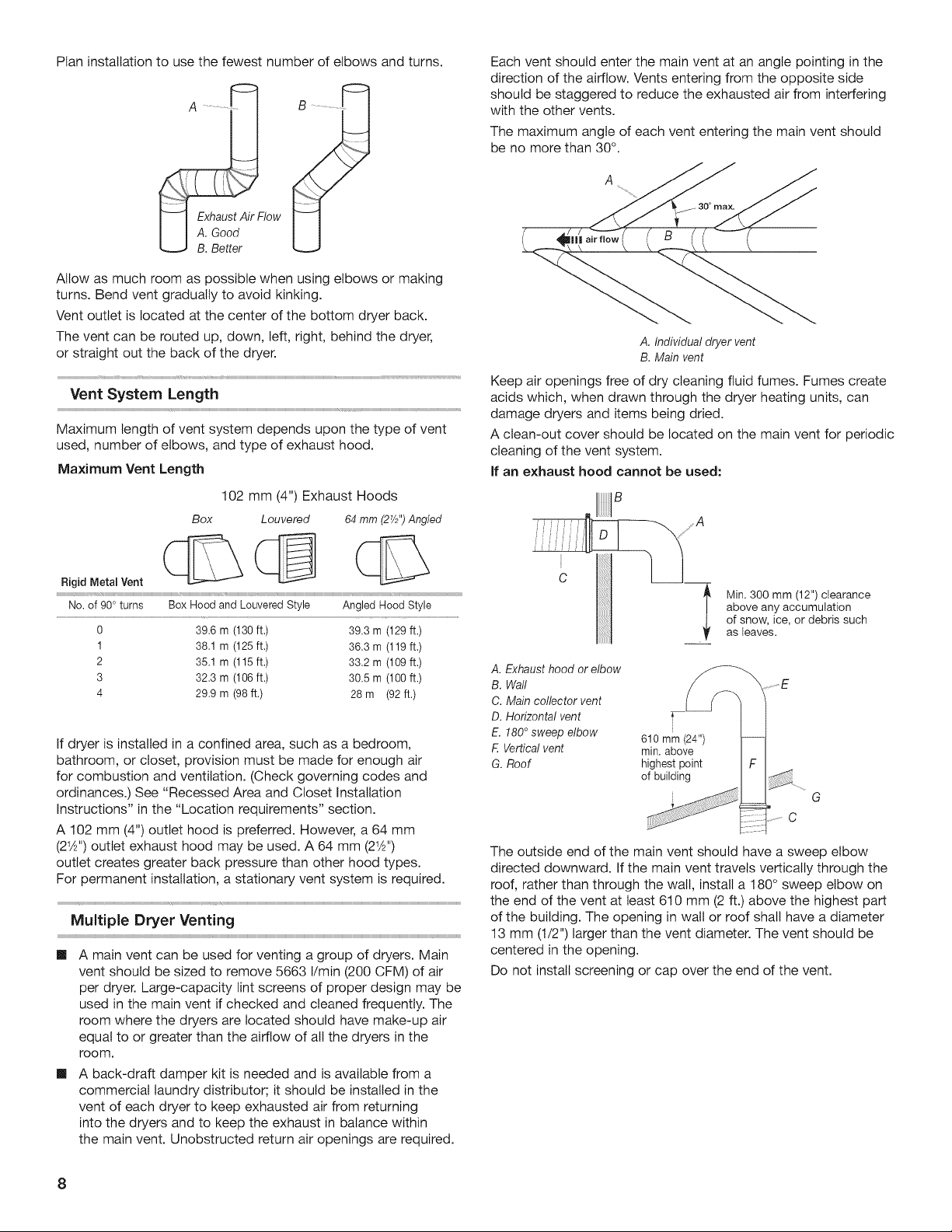
Plan
installation
to
use
the
fewest
number
of
elbows
and
turns.
Exhaust
Air
Flow
A.
Good
B.
Better
Allow
as
much
room
as
possible
when
using
eloows
or
making
turns.
Bend
vent
gradually
to
avoid
kinking.
Vent
outlet
is
located
at
the
center
of
the
bottom
dryer
back.
The
vent
can
be
routed
up,
down,
left,
right,
behind
the
dryer,
or
straight
out
the
back
of
the
dryer.
Vent
System
Length
Maximum
length
of
vent
system
depends
upon
the
type
of
vent
used,
number
of
elbows,
and
type
of
exhaust
hood.
Maximum
Vent
Length
102
mm
(4")
Exhaust
Hoods
Box
64
mm
(2%")
Angled
Rigid
Metal
Vent
qh
\
Lf
Louvered
No.
of
90°
turns
Box
Hood
and
Louvered
Style
Angled
Hood
Style
0
39.6
m
(130
ft.)
39.3
m
(129
ft.)
1
38.1
m
(1265
ft.)
36.3
m
(119
ft.)
2
35.1
m
(115
ft)
33.2
m
(109
ft.)
3
32.3
m
(106
ft)
30.5
m
(100
ft.)
4
29.9
m
(98
ft.)
28m
(92
ft.)
if
dryer
is
installed
in
a
confined
area,
such
as
a
bedroom,
bathroom,
or
closet,
provision
must
be
made
for
enough
air
for
combustion
and
ventilation.
(Check
governing
codes
and
ordinances.)
See
“Recessed
Area
and
Closet
Installation
instructions”
in
the
“Location
requirements”
section.
A
102
mm
(4")
outlet
hood
is
preferred.
However,
a
64
mm
(2'%2")
outlet
exhaust
hood
may
be
used.
A
64
mm
(214")
outlet
creates
greater
back
pressure
than
other
hood
types.
For
permanent
installation,
a
stationary
vent
system
is
required.
Multiple
Dryer
Venting
@
A
main
vent
can
be
used
for
venting
a
group
of
dryers.
Main
vent
should
be
sized
to
remove
5663
|/min
(200
CFM)
of
air
per
dryer.
Large-capacity
lint
screens
of
proper
design
may
be
used
in
the
main
vent
if
checked
and
cleaned
frequently.
The
room
where
the
dryers
are
located
should
have
make-up
air
equal
to
or
greater
than
the
airflow
of
all
the
dryers
in
the
room.
—@
A
back-draft
damper
kit
is
needed
and
is
available
from
a
commercial
laundry
distributor;
it
should
be
installed
in
the
vent
of
each
dryer
to
keep
exhausted
air
from returning
into
the
dryers
and
to
keep
the
exhaust
in
balance
within
the
main
vent.
Unobstructed
return
air
openings
are
required.
Each
vent
should
enter
the
main
vent
at
an
angle
pointing
in
the
direction
of
the
airflow.
Vents
entering
from
the
opposite
side
should
be
staggered
to
reduce
the
exhausted
air
from
interfering
with
the
other
vents.
The
maximum
angle
of
each
vent
entering
the
main
vent
should
be
no
more
than
30°.
A
Gilt
air
Fow
(
(8
‘a
(
A.
Individual
dryer
vent
B.
Main
vent
Keep
air
openings
free
of
dry
cleaning
fluid
fumes.
Fumes
create
acids
which,
when
drawn
through
the
dryer
heating
units,
can
damage
dryers
and
items
being
dried.
A
clean-out
cover
should
be
located
on
the
main
vent
for
periodic
cleaning
of
the
vent
system.
If
an
exhaust
hood
cannot
be
used:
Min.
300
mm
(12")
clearance
above
any
accumulation
of
snow,
ice,
or
debris
such
as
leaves.
A.
Exhaust
hood
or
elbow
B.
Wall
EF
C.
Main
collector
vent
D.
Horizontal
vent
ro
E.
180°
sweep
elbow
610
mm
(24")
F.
Vertical
vent
min.
above
G.
Roof
highest
point
of
building
a,
¥
SP
C
The
outside
end
of
the
main
vent
should
have
a
sweep
elbow
directed
downward.
If
the
main
vent
travels
vertically
through
the
roof,
rather
than
through
the
wail,
install
a
180°
sweep
elbow
on
the
end
of
the
vent
at
least
610
mm
(2
ft.)
above
the
highest
part
of
the
building.
The
opening
in
wail
or
roof
shall
have
a
diameter
13
mm
(1/2")
larger
than
the
vent
diameter.
The
vent
should
be
centered
in
the
opening.
Do
not
install
screening
or
cap
over
the
end
of
the
vent.
Loading ...
Loading ...
Loading ...