Loading ...
Loading ...
Loading ...
19
Installation Instructions
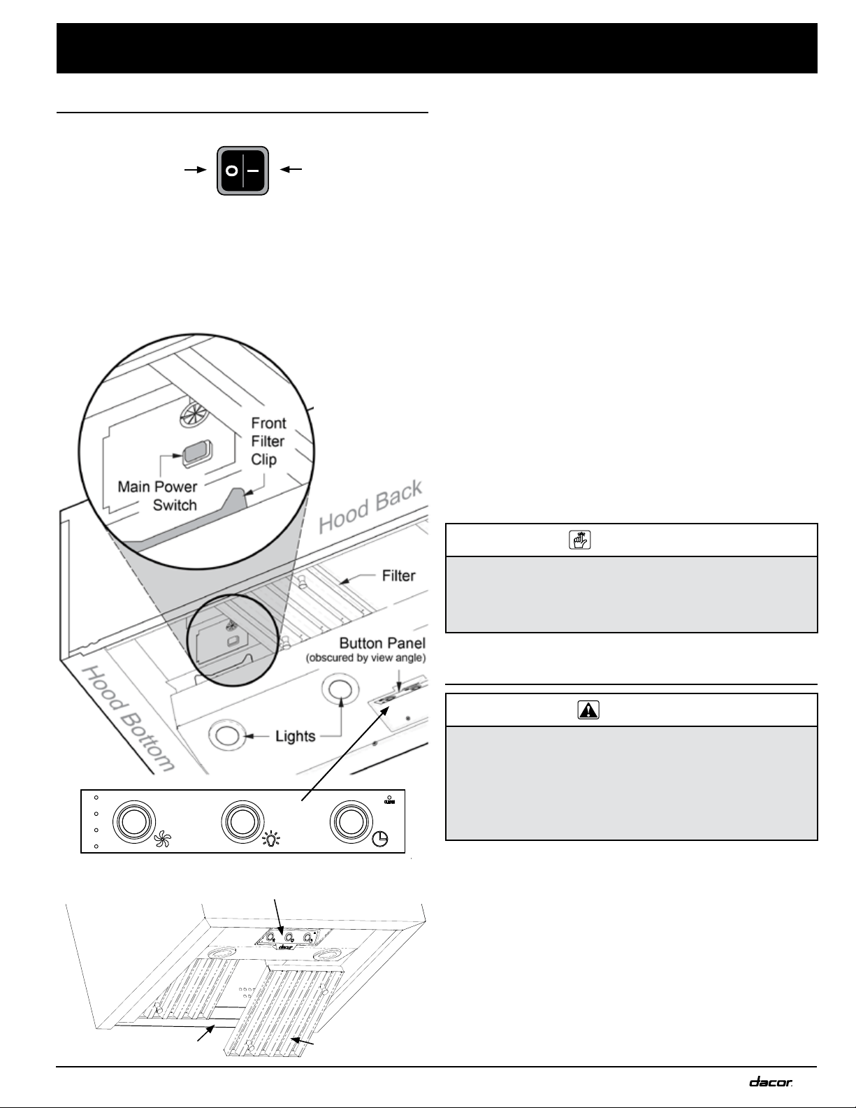
FAN LIGHTS TIMER
Feature-Button Panel
Filter
Grease channel
Verifying the Setup
1. Turn OFF the main power switch.
2. Turn power ON at the circuit panel or fusebox.
3. Turn ON the main power switch.
The button panel flashes several times during startup.
4. Insert the filters gently:
a. Do not scratch the back of the grease channel!
b. Set the front edge into the clip, and press forward.
OFF
ON
c. (Taking care not to scratch the grease channel or
other hood/filter surfaces) Lift the rear edge above
the grease channel.
d. Set the filter rear edge onto the grease channel.
5. On the hood feature-button panel, press the LIGHTS
button to verify that all lights turn on.
6. Press the LIGHTS button again to turn the lights to the
Low setting.
7. Press the LIGHTS button again to turn the lights off.
8. Press/release the FAN button to verify that one fan-
speed indicator turns on and the fan is on at low speed.
9. Slowly press/release the FAN button three times:
a. to verify that the number of lights and fan speed
increases each time, then
b. press the FAN button again to turn the fan OFF
If the Hood Fails to Function Correctly:
1. Verify that power is supplied to the hood.
2. Remove the right-most filter to access the main power
switch behind the button panel, and confirm the main
power switch is ON.
3. Verify that the electrical connections are correctly done.
4. Perform the Verify the Setup procedure again.
IMPORTANT
If the hood still does not work, contact Dacor Distinctive
Service: (800) 793-0093 x2822. Do not try to repair the
appliance yourself. Dacor is not responsible for service
required to correct a faulty installation.
Installation Checklist
WARNING
• To ensure a safe and correct installation, this checklist
should be completed by the installer to ensure com-
plete and proper installation.
• The homeowner is responsible for the Dacor range
hood’s proper installation, the importance of which can-
not be overstated.
□ The hood is properly attached to the wall per the instruc-
tions on Pgs. 11 and 16.
□ Ducting is fully installed; joints are secured with sheet-
metal screws and wrapped with foil tape. See Pg. 19.
□ The hood is wired/grounded as instructed and per all
applicable electric codes. See Pgs. 7, 19.
□ Filters are assembled as instructed on Pg. 18.
□ The setup was verified.
□ Any problems were noted on the warranty card or during
the online warranty activation. The warranty card was
completed and mailed, or the warranty activated online.
Main Power
Switch Detail/
Hood Bottom
Loading ...
Loading ...
Loading ...