Loading ...
Loading ...
Loading ...
27
INSTALLATION
Check the appliance is electrically safe when you have nished.
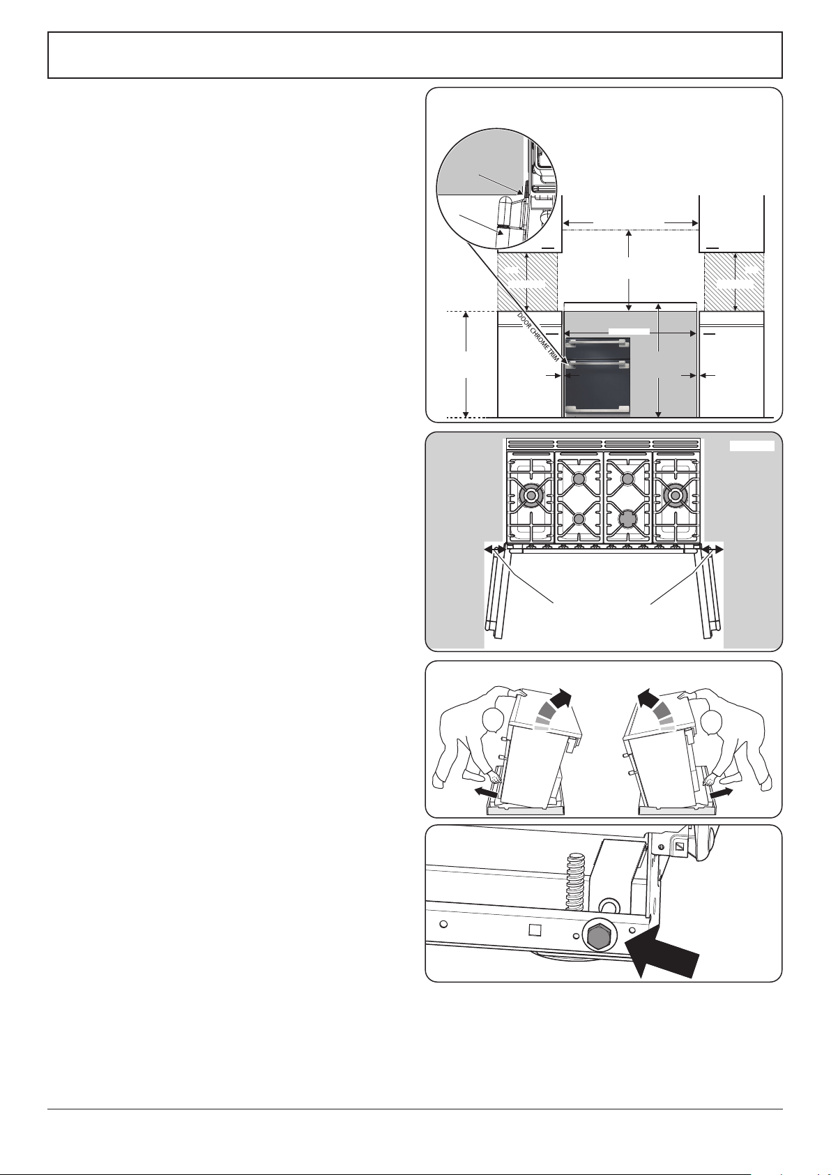
ArtNo.110-0004 - 110 Cooker min spacings
*See note
*See note
*Note
Height to Flue Trim
925 mm min
950 mm max
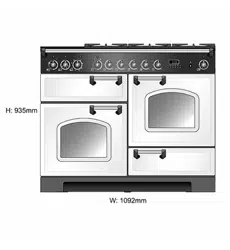
Height to Hotplate
910 mm min
935 mm max
650 mm min
410 mm min
410 mm min
Wall
1102 mm min
1092 mm
Wall
WORKTOP
DOOR CHROME TRIM
DOOR HANDLE
check cookerhood instructions for actual dimensions
130 mm minimum
*Note
5mm gap if the appliance is 30mm in front of the
kitchen cabinets
9mm gap if the appliance is to be ush tted
between kitchen cabinets
Fig. 9.2
Fig. 9.3
When Fitting Between Kitchen Cabinets
We recommend that you either:
A. Fit the range so that any cabinet doors are at least
30 mm behind the range door fronts. Note that this may
require an inll piece behind the range. We recommend
a gap of 1102 mm between units to allow for moving
the range. DO NOT box the range in – it must be
possible to move the range in and out for cleaning and
servicing.
B. Leave a gap of at least 9mm on either side of the range
(a 1110 mm gap between units) (Fig. 9.2 and Fig. 9.3).
The range should be positioned centrally.
We also recommend that you DO NOT nal x any adjacent
cabinets until the range is installed. Decorative mouldings or
handles on cabinet doors and fronts may interfere with the
opening of the oven doors.
Moving the cooker
n
On no account try and move the cooker while it is
plugged into the electricity supply.
n
The cooker is very heavy, so take extra care.
We recommend that two people manoeuvre the cooker.
Make sure that the oor covering is rmly xed, or removed,
to prevent it being disturbed when moving the cooker
around.
To help you, there are two levelling rollers at the back, and
two screw-down levelling feet at the front.
Remove the polystyrene base pack. From the front, tilt
the cooker backwards and remove the front half of the
polystyrene base (Fig. 9.4).
Repeat from the back and remove the rear half of the
polystyrene base.
Lowering the two rear rollers
To adjust the height of the rear of the cooker, rst t a 13 mm
spanner or socket wrench onto the hexagonal adjusting
nut (Fig. 9.5). Rotate the nut – clockwise to raise – counter-
clockwise to lower.
Make 10 complete (360°) turns clockwise.
Make sure you lower BOTH REAR ROLLERS.
Fig. 9.4
Fig. 9.5
Loading ...
Loading ...
Loading ...