
Owner's Manual
ICRRFTSMRW[
23.0 HP
ELECTRIC START
48" MOWER
AUTOMATIC
GARDEN TRACTOR
Model No.
917.275240
• Safety
• Assembly
• Operation
• Maintenance
• Repair Parts
CAUTION:
Read and follow all Safety
Rules and Instructions before
operating this equipment.
For answers to your questions
about this product, Call:
1-800-659-5917
Sears Craftsman Help Line
5 am - 5 pro, Mon- Sat
Sears, Roebuck and Co., Hoffman Estates, II 60179
Visit our Craftsman website:www.sears.com/craftsman
Warranty...............................................2
SafetyRules.........................................3
ProductSpecifications..........................6
Assembly..............................................8
Operation............................................13
MaintenanceSchedule......................20
Maintenance ....................................... 20
Service and Adjustments .................... 26
Storage ............................................... 34
Troubleshooting ................................. 35
Repair Parts ........................................ 39
Parts Ordering ..................... Back Cover
LIMITED TWO YEAR WARRANTY ON CRAFTSMAN RIDING EQUIPMENT PARTS
For two (2) years from the date of purchase, if this Craftsman Riding Equipment is
maintained, lubricated and tuned up according to the instructions in the owner's
manual, Sears will repair or replace, free of charge, any parts found to be defective in
material or workmanship. Warranty service is available free of charge by returning your
Craftsman riding equipment to your nearest Sears Service Center. In-home warranty
service is available but a trip charge will apply. This warranty applies only while this
product is in the United States.
This Warranty does not cover:
• Expendable items which become worn during normal use, such as blades, spark
plugs, air cleaners, belts and oil filters.
• Tire replacement or repair caused by punctures from outside objects, such as nails,
thorns, stumps, or glass.
• Repairs necessary because of operator abuse, including but not limited to, damage
caused by towing objects beyond the capability of the riding equipment, impacting
objects that bend the frame or crankshaft, or over speeding the engine.
• Repairs necessary because of operator negligence, including but not limited to,
electrical and mechanical damage caused by improper storage, failure to use the
proper grade and amount of engine oil, failure to keep the deck clear of flammable
debris, or the failure to maintain the equipment according to the instructions con-
tained in the owner's manual.
• Engine (fuel system) cleaning or repairs caused by fuel determined to be contami-
nated or oxidized (stale). In general, fuel should be used within thirty (30) days of its
purchase date.
• Riding equipment used for commercial or rental purposes. A product is "used for
commercial purpose" if is used for any purpose other than single family household
dwellings or in usage where profit is made.
LIMITED 90 DAY WARRANTY ON BATTERY
For ninety (90) days from date of purchase, if any battery included with this riding
equipment proves defective in material or workmanship and our testing determines the
battery will not hold a charge, Sears will replace the battery at no charge. Warranty
service is available free of charge by returning your Craftsman riding equipment to
your nearest Sears Service Center. In-home warranty service is available but a trip
charge will apply. This warranty applies only while this product is in the United States.
TO LOCATE THE NEAREST SEARS SERVICE CENTER OR TO SCHEDULE IN-HOME
WARRANTY SERVICE, SIMPLY CONTACT SEARS AT 1-800-4-MY-HOME
This Warranty gives you specific legal rights, and you may also have other rights which
may vary from state to state.
Sears, Roebuck and Co., D/817 WA, Hoffman Estates, IL 60179
2
IMPORTANT: This cutting machine is capable of amputating hands and feet and
throwing, objects. Failure to observe the following safety instructions could result in
serious injury or death.
GENERAL OPERATION
• Read, understand, and follow all
instructions in the manual and on the
machine before starting.
• Only allow responsible adults, who are
familiar with the instructions, to
operate the machine.
• Clear the area of objects such as
rocks, toys, wire, etc., which could be
picked up and thrown by the blade.
• Be sure the area is clear of other
people before mowing. Stop machine
if anyone enters the area.
• Never carry passengers.
• Do not mow in reverse unless abso-
lutely necessary. Always look down
and behind before and while backing.
• Be aware of the mower discharge
direction and do not point it at anyone.
Do not operate the mower without
either the entire grass catcher or the
guard in place.
• Slow down before turning.
• Never leave a running machine
unattended. Always turn off blades, set
parking brake, stop engine, and
remove keys before dismounting.
• Turn off blades when not mowing.
• Stop engine before removing grass
catcher or unclogging chute.
• Mow only in daylight or good artificial
light.
• Do not operate the machine while
under the influence of alcohol or
drugs.
• Watch for traffic when operating near
or crossing roadways.
• Use extra care when loading or
unloading the machine into a trailer or
truck.
• Data indicates that operators, age 60
years and above, are involved in a
large percentage of riding mower-
related injuries. These operators
should evaluate their ability to operate
the riding mower safely enough to
protect themselves and others from
serious injury.
• Keep machine free of grass, leaves or
other debris build-up which can touch
hot exhaust / engine parts and bum.
Do not allow the mower deck to plow
leaves or other debris which can cause
build-up to occur. Clean any oil or fuel
spillage before operating or storing the
machine. Allow machine to cool before
storage.
SLOPE OPERATION
Slopes are a major factor related to loss-
of-control and tipover accidents, which
can result in severe injury or death. All
slopes require extra caution. If you
cannot back up the slope or if you feel
uneasy on it, do not mow it.
DO;
• Mow up and down slopes, not across.
• Remove obstacles such as rocks, tree
limbs, etc.
• Watch for holes, ruts, or bumps.
Uneven terrain could overturn the
machine. Tall grass can hide ob-
stacles.
• Use slow speed. Choose a low gear
so that you will not have to stop or shift
while on the slope.
• Follow the manufacturer's recommen-
dations for wheel weights or counter-
weights to improve stability.
• Use extra care with grass catchers or
other attachments. These can change
the stability of the machine.
• Keep all movement on the slopes slow
and gradual. Do not make sudden
changes in speed or direction.
• Avoid starting or stopping on a slope. If
tires lose traction, disengage the
blades and proceed slowly straight
down the slope.
DO NOT:
• Do not turn on slopes unless neces-
sary, and then, turn slowly and
gradually downhill, if possible.
• Do not mow near drop-offs, ditches, or
embankments. The mower could
suddenly turn over if a wheel is over
the edge of a cliff or ditch, or if an edge
caves in.
• Do not mow on wet grass. Reduced
traction could cause sliding.
• Do nottry to stabilize the machine by
putting your foot on the ground.
• Do not use grass catcher on steep
slopes.
3
CHILDREN
Tragic accidents can occur if the operator
is not alert to the presence of children.
Children are often attracted to the
machine and the mowing activity. Never
assume that children will remain where
you last saw them.
• Keep children out of the mowing area
and under the watchful care of another
responsible adult.
• Be alert and turn machine off if
children enter the area.
• Before and when backing, look behind
and down for small children.
• Never carry children. They may fall off
and be seriously injured or interfere
with safe machine operation.
• Never allow children to operate the
machine.
• Use extra care when approaching
blind corners, shrubs, trees, or other
objects that may obscure vision.
SERVICE
• Use extra care in handling gasoline
and other fuels. They are flammable
and vapors are explosive.
-Use only an approved container.
-Never remove gas cap or add fuel
with the engine running. Allow
engine to cool before refueling. Do
not smoke.
-Never refuel the machine indoors.
- Never store the machine or fuel
container inside where there is an
open flame, such as a water heater.
• Never run a machine inside a closed
area.
• Keep nuts and bolts, especially blade
attachment bolts, tight and keep
equipment in good condition.
• Never tamper with safety devices.
Check their proper operation regularly.
• Keep machine free of grass, leaves, or
other debris build-up. Clean oil or fuel
spillage. Allow machine to cool before
storing.
• Stop and inspect the equipment if you
strike an object. Repair, if necessary,
before restarting.
• Never make adjustments or repairs
with the engine running.
• Grass catcher components are subject
to wear, damage, and deterioration,
which could expose moving parts or
allow objects to be thrown. Frequently
check components and replace with
manufacturer's recommended parts,
when necessary.
• Mower blades are sharp and can cut.
Wrap the blade(s) or wear gloves, and
use extra caution when servicing
them.
• Check brake operation frequently.
Adjust and service as required.
• Be sure the area is clear of other
people before mowing. Stop machine
if anyone enters the area.
• Never carry passengers or children
even with the blades off.
• Do not mow in reverse unless abso-
lutely necessary. Always look down
and behind before and while backing.
• Never carry children. They may fall off
and be seriously injured or interfere
with safe machine operation.
• Keep children out of the mowing area
and under the watchful care of another
responsible adult.
• Be alert and turn machine off if
children enter the area.
• Before and when backing, look behind
and down for small children.
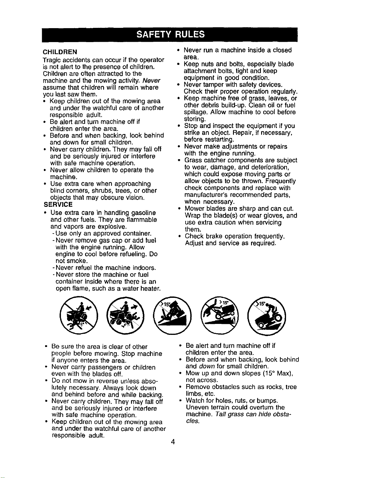
• Mow up and down slopes (15 ° Max),
not across.
• Remove obstacles such as rocks, tree
limbs, etc.
• Watch for holes, ruts, or bumps.
Uneven terrain could overturn the
machine. Tall grass can hide obsta-
cles.
4
• Use slow speed. Choose a low gear
so that you will not have to stop or shift
while on the slope.
• Avoid starting or stopping on a slope. If
tires lose traction, disengage the
blades and proceed slowly straight
down the slope.
• If machine stops while going uphill,
disengage blades, shift into reverse
and back down slowly.
• Do not turn on slopes unless neces-
sary, and then, turn slowly and
gradually downhill, if possible.
_:_Look for this symbol to point out
important safety precautions. It means
CAUTION!!! BECOMEAWAREH!YOUR
SAFETY IS INVOLVED.
• kOAUTION" In order to prevent acciden-
tal starting when setting up, transporting,
adjusting or making repairs always
disconnect spark plug wire and place
wire where it cannot contact spark plug.
_kCAUTION: Do not coast down a hill in
neutral, you may lose control of the
tractor.
_,CAUTION: Tow only the attachments
that are recommended by and comply
with specifications of the manufacturer of
your tractor. Use common sense when
towing. Operate only at the lowest
possible speed when on a slope. Too
heavy of a load, while on a slope, is
dangerous. Tires can lose traction with
the ground and cause you to lose control
of your tractor.
_I_WARNING: Engine exhaust, some of
its constituents, and certain vehicle
components contain or emit chemicals
known to the State of California to cause
cancer and birth defects or other
reproductive harm.
_WARNING: Battery posts, terminals
and related accessories contain lead
and lead compounds, chemicals known
to the State of California to cause cancer
and birth defects or other reproductive
harm. Wash hands after handling.
5
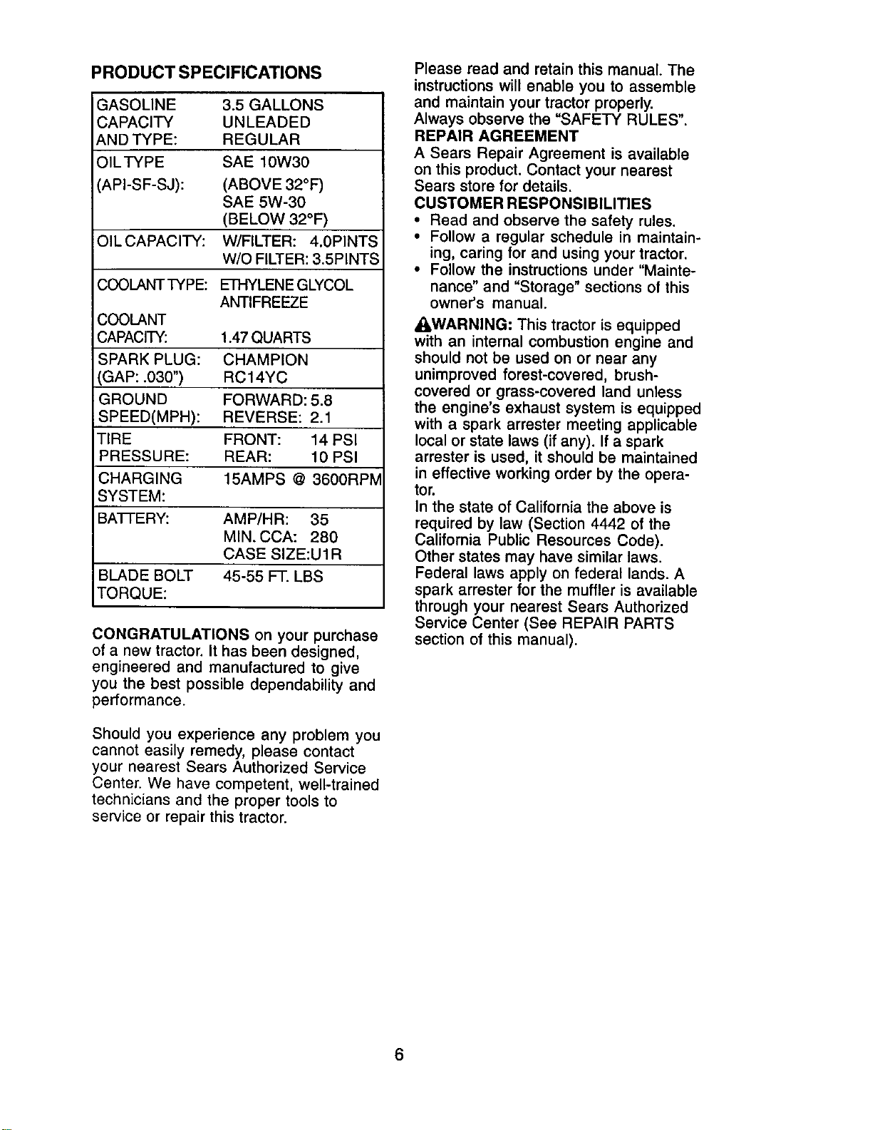
PRODUCT SPECIFICATIONS
GASOLINE
CAPACITY
AND TYPE:
OILTYPE
API-SF-SJ):
3.5 GALLONS
UNLEADED
REGULAR
SAE 10W30
(ABOVE 32°F)
SAE 5W-30
(BELOW 32°F)
OILCAPACITY: W/FILTER: 4.0PINTS
W/O FILTER: 3.SPINTS
COOLANT TYPE: ETHYLENE GLYCOL
ANTIFREEZE
COOLANT
CAPACITY: 1.47 QUARTS
SPARK PLUG: CHAMPION
(GAP: .030") RC14YC
GROUND FORWARD: 5.8
SPEED(MPH): REVERSE: 2.1
TIRE FRONT: 14 PSI
PRESSURE: REAR: 10 PSI
CHARGING 15AMPS @ 3600RPM
SYSTEM:
BA'I-FERY: AMP/HR: 35
MIN. CCA: 280
CASE SIZE:U1R
BLADE BOLT 45-55 FT. LBS
TORQUE:
CONGRATULATIONS on your purchase
of a new tractor. It has been designed,
engineered and manufactured to give
you the best possible dependability and
performance.
Should you experience any problem you
cannot easily remedy, please contact
your nearest Sears Authorized Service
Center. We have competent, well-trained
technicians and the proper tools to
service or repair this tractor.
Please read and retain this manual. The
instructions will enable you to assemble
and maintain your tractor properly.
Always observe the "SAFETY RULES".
REPAIR AGREEMENT
A Sears Repair Agreement is available
on this product. Contact your nearest
Sears store for details.
CUSTOMER RESPONSIBILITIES
• Read and observe the safety rules.
• Follow a regular schedule in maintain-
ing, caring for and using your tractor.
• Follow the instructions under "Mainte-
nance" and "Storage" sections of this
owner's manual.
_&WARNING: This tractor is equipped
with an internal combustion engine and
should not be used on or near any
unimproved forest-covered, brush-
covered or grass-covered land unless
the engine's exhaust system is equipped
with a spark arrester meeting applicable
local or state laws (if any). If a spark
arrester is used, it should be maintained
in effective working order by the opera-
tor.
In the state of California the above is
required by law (Section 4442 of the
California Public Resources Code).
Other states may have similar laws.
Federal laws apply on federal lands. A
spark arrester for the muffler is available
through your nearest Sears Authorized
Service Center (See REPAIR PARTS
section of this manual).
6
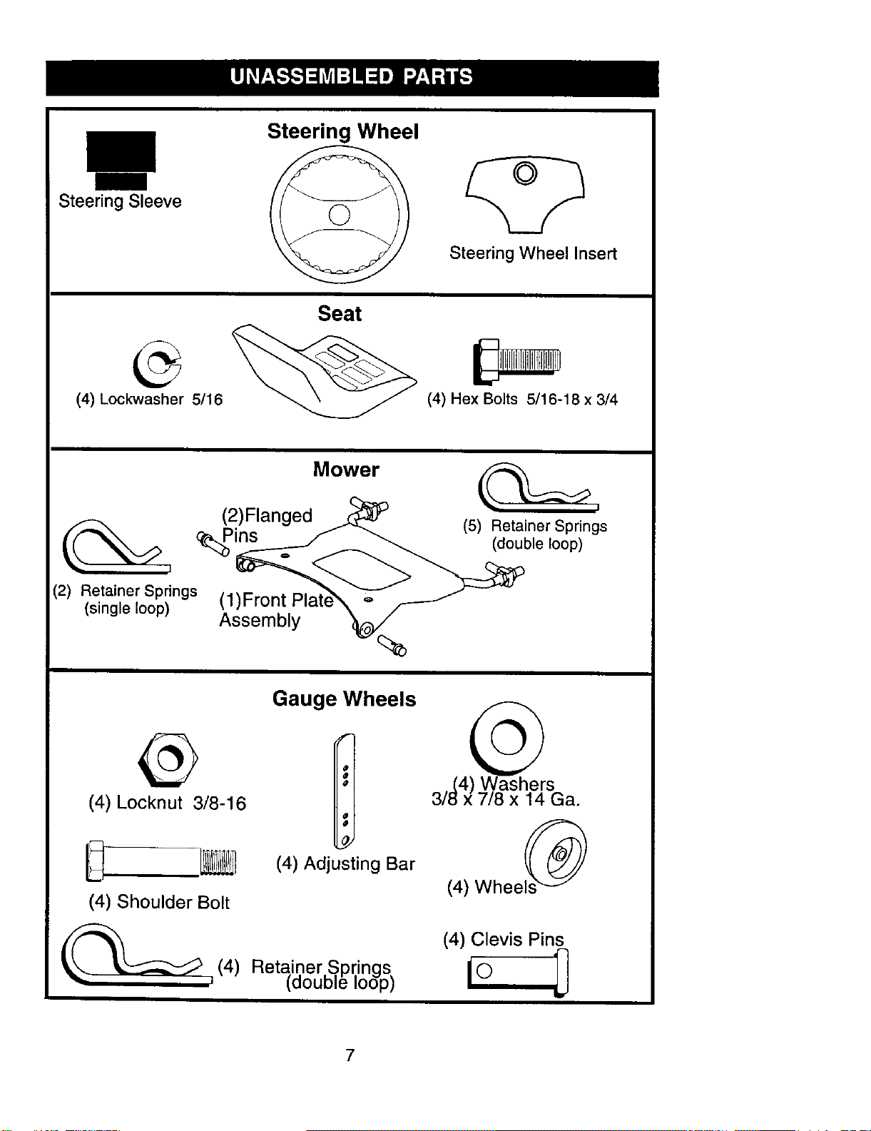
Steering Sleeve
Steering Wheel
Steering Wheel Insert
(4) Lockwasher 5/16
Seat
(4) Hex Bolts 5/16-18 x 3/4
(2) Retainer Springs
(single loop)
Mower
(2)Flanged
_ins
(1)Front
Assembly
(5) Retainer Springs
(double loop)
@
(4) Locknut 3/8-16
(4) Shoulder Bolt
_(4)
Gauge Wheels
(4) Adjusting Bar
Retainer S,prings
taouD e oop)
3,_(4) Washers
/t_x 7/8 x 14 Ga.
(4) Wheels_
(4) Clevis Pins
7
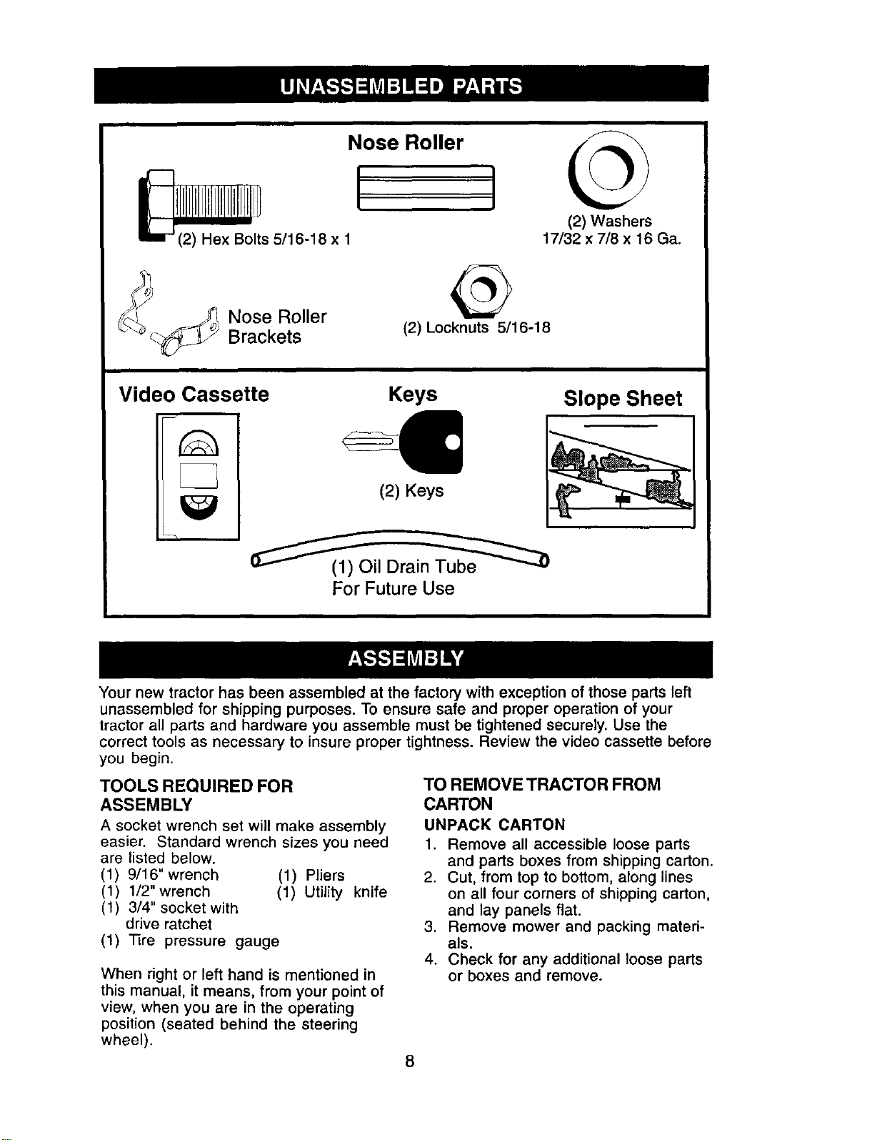
Nose Roller
(2) Washers
17/32 x 7/8 x 16 Ga.
Nose Roller
Brackets
(2) Locknuts 5/16-18
Video Cassette
Keys
(2) Keys
Slope Sheet
For Future Use
Your new tractor has been assembled at the factory with exception of those parts left
unassembled for shipping purposes. To ensure safe and proper operation of your
tractor all parts and hardware you assemble must be tightened securely. Use the
correct tools as necessary to insure proper tightness. Review the video cassette before
you begin.
TOOLS REQUIRED FOR
ASSEMBLY
A socket wrench set will make assembly
easier. Standard wrench sizes you need
are listed below.
(1) 9/16" wrench (1) Pliers
(1) 1/2"wrench (1) Utility knife
(1) 3/4" socket with
drive ratchet
(1) Tire pressure gauge
When right or left hand is mentioned in
this manual, it means, from your point of
view, when you are in the operating
position (seated behind the steering
wheel).
TO REMOVE TRACTOR FROM
CARTON
UNPACK CARTON
1. Remove all accessible loose parts
and parts boxes from shipping carton.
2. Cut, from top to bottom, along lines
on all four corners of shipping carton,
and lay panels flat.
3. Remove mower and packing materi-
als.
4. Check for any additional loose parts
or boxes and remove.
8
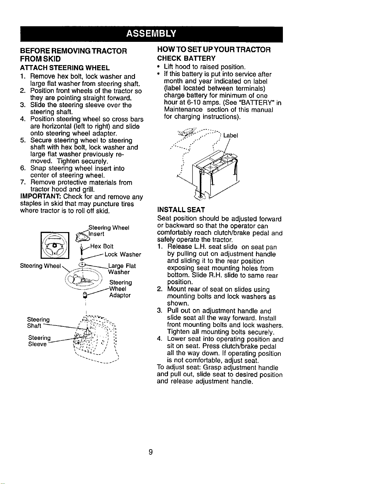
BEFORE REMOVING TRACTOR
FROM SKID
ATrACH STEERING WHEEL
1. Remove hex bolt, lock washer and
large flat washer from steering shaft.
2. Position front wheels of the tractor so
they are pointing straight forward.
3. Slide the steering sleeve over the
steering shaft.
4. Position steering wheel so cross bars
are horizontal (left to right) and slide
onto steering wheel adapter.
5. Secure steering wheel to steering
shaft with hex bolt. lock washer and
large flat washer previously re-
moved. Tighten securely.
6. Snap steering wheel insert into
center of steering wheel.
7. Remove protective materials from
tractor hood and grill.
IMPORTANT: Check for and remove any
staples in skid that may puncture tires
where tractor is to roll off skid.
jSteering Wheel
_ _nsert
_/Hex Bolt
Lock Washer
Steering Wheel\ _Large Flat
_,_1 Washer
_If Adaptor
Steering .......
Shaft
Steering
Sleeve
HOW TO SET UP YOUR TRACTOR
CHECK BA'n'ERY
• Lift hood to raised position.
• If this battery is put into service after
month and year indicated on label
(label located between terminals)
charge battery for minimum of one
hour at 6-10 amps. (See "BATTERY" in
Maintenance section of this manual
for charging instructions).
-_-_,- ,-- , Label
i,
f
INSTALL SEAT
Seat position should be adjusted forward
or backward so that the operator can
comfortably reach clutch/brake pedal and
safely operate the tractor.
1. Release L.H. seat slide on seat pan
by pulling out on adjustment handle
and sliding it to the rear position
exposing seat mounting holes from
bottom• Slide R.H. slide to same rear
position.
2. Mount rear of seat on slides using
mounting bolts and lock washers as
shown.
3. Pull out on adjustment handle and
slide seat all the way forward. Install
front mounting bolts and lock washers.
Tighten all mounting bolts securely.
4. Lower seat into operating position and
sit on seat. Press clutch/brake pedal
all the way down• If operating position
is not comfortable, adjust seat•
To adjust seat: Grasp adjustment handle
and pull out, slide seat to desired position
and release adjustment handle.
9
L.h. Seat Slide
Seat Pan_
Adjustment _ \ .\'_
Handle_. "X_C.p _
Lock-_ "->,_;._\
Washe_'_
Mou°t, Bo,tsli
Seat
_R.H. Seat Slide
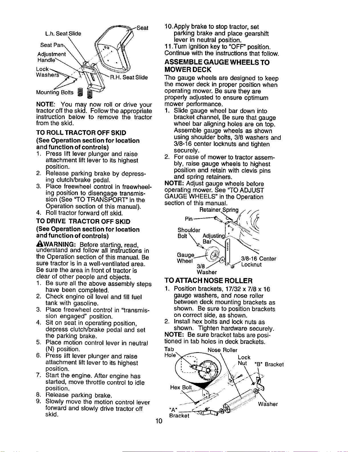
NOTE: You may now roll or drive your
tractor off the skid. Follow the appropriate
instruction below to remove the tractor
from the skid.
TO ROLL TRACTOR OFF SKID
(See Operation section for location
and function of controls)
1. Press lift lever plunger and raise
attachment lift lever to its highest
position.
2. Release parking brake by depress-
ing clutch/brake pedal.
3. Place freewheel control in freewheel-
ing position to disengage transmis-
sion (See "TO TRANSPORT" in the
Operation section of this manual).
4. Roll tractor forward off skid.
TO DRIVE TRACTOR OFF SKID
(See Operation section for location
and function of controls)
_WARNING: Before startinq read
understand and follow all instruct one in
the Operation section of this manual. Be
sure tractor is in a well-ventilated area.
Be sure the area in front of tractor is
clear of other people and objects.
1. Be sure all the above assembly steps
have been completed.
2. Check engine oil level and fill fuel
tank with gasoline.
3. Place freewheel control in "transmis-
sion engaged" position.
4. Sit on seat in operating position,
depress clutch/brake pedal and set
the parking brake.
5. Place motion control lever in neutral
(N) position.
6. Press lift lever plunger and raise
attachment lift lever to its highest
position.
7. Start the engine. After engine has
started, move throttle control to idle
position.
8. Release parking brake.
9. Slowly move the motion control lever
forward and slowly drive tractor off
skid.
10.Apply brake to stop tractor, set
parking brake and place gearshift
lever in neutral position.
11 .Turn ignition key to "OFF" position.
Continue with the instructions that follow.
ASSEMBLE GAUGE WHEELS TO
MOWER DECK
The gauge wheels are designed to keep
the mower deck in proper position when
operating mower. Be sure they are
properly adjusted to ensure optimum
mower performance.
1. Slide gauge wheel bar down into
bracket channel, Be sure that gauge
wheel bar aligning holes are on top.
Assemble gauge wheels as shown
using shoulder bolts, 3/8 washers and
3/8-16 center Iocknuts and tighten
securely.
2. For ease of mower to tractor assem-
bly, raise gauge wheels to highest
position and retain with clevis pins
and spring retainers.
NOTE: Adjust gauge wheels before
operating mower. See "TO ADJUST
GAUGE WHEELS" in the Operation
section of this manual.
Retainer,,_ ring ///F_£.
Pin-------%
Shoulder
Bolt \ Adjustin
Gauge t_ _,
Wheel _,J_
3/8
Washer
3/8-16 Center
JLocknut
TO ATTACH NOSE ROLLER
1. Position brackets, 17/32 x 7/8 x 16
gauge washers, and nose roller
between deck mounting brackets as
shown. Be sure to position brackets
on correct side, as shown.
2. Install hex bolts and lock nuts as
shown. Tighten hardware securely.
NOTE: Be sure bracket tabs are posi-
tioned in tab holes in deck brackets.
Tab Nose Roller
Lock
"B" Bracket
Hex Bolt
"A"
Bracket
10
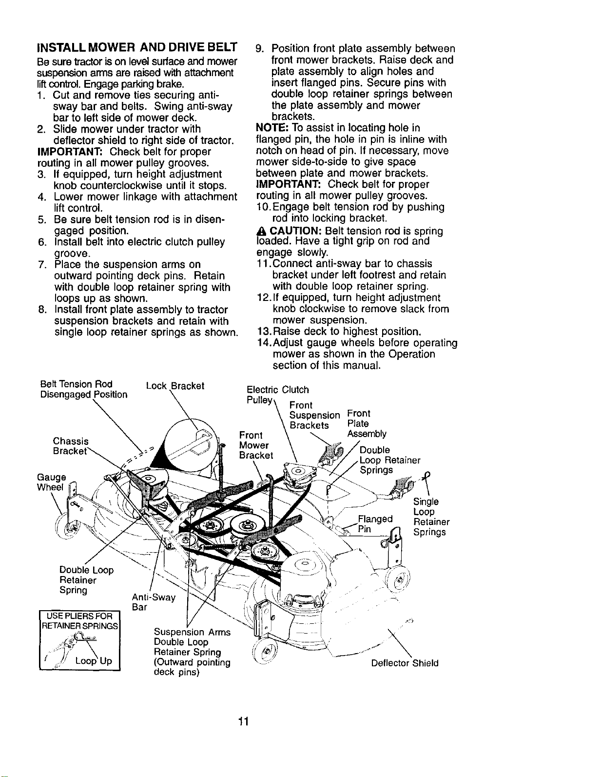
INSTALL MOWER AND DRIVE BELT
Be sure tractor is on level surface and mower
suspension arms are raised with attachment
lift control. Engage parking brake.
1. Cut and remove ties securing anti-
sway bar and belts. Swing anti-sway
bar to left side of mower deck.
2. Slide mower under tractor with
deflector shield to right side of tractor.
IMPORTANT: Check belt for proper
routing in all mower pulley grooves.
3. If equipped, turn height adjustment
knob counterclockwise until it stops.
4. Lower mower linkage with attachment
lift control.
5. Be sure belt tension rod is in disen-
gaged position.
6. Install belt into electric clutch pulley
groove.
7. Place the suspension arms on
outward pointing deck pins. Retain
with double loop retainer spring with
loops up as shown.
8. Install front plate assembly to tractor
suspension brackets and retain with
single loop retainer springs as shown.
Belt Tension Rod Lock Bracket
Disengaged Position
Chassis _;
Gauge
Wheel
9. Position front plate assembly between
front mower brackets. Raise deck and
plate assembly to align holes and
insert flanged pins. Secure pins with
double loop retainer springs between
the plate assembly and mower
brackets.
NOTE: To assist in locating hole in
flanged pin, the hole in pin is inline with
notch on head of pin. If necessary, move
mower side-to-side to give space
between plate and mower brackets.
IMPORTANT: Check belt for proper
routing in all mower pulley grooves.
10.Engage belt tension rod by pushing
rod into locking bracket.
IAoaCAUTION: Belt tension rod is spring
ded. Have a tight grip on rod and
engage slowly.
11.Connect anti-sway bar to chassis
bracket under left footrest and retain
with double loop retainer spring.
12.1f equipped, turn height adjustment
knob clockwise to remove slack from
mower suspension.
13.Raise deck to highest position.
14.Adjust gauge wheels before operating
mower as shown in the Operation
section of this manual.
Electric Clutch
Pulley\ Front
\ Suspension Front
Front \Brackets PlateAssembly
Mower \
Bracket\
/Loop Retainer
Single
Loop
Retainer
Springs
Double Loop
Retainer
Spring
USE PLIERS FOR I
RETAINER SPRINGS
,. Up
Anti-Sway
Bar
Suspension Arms
Double Loop
Retainer Spring
(Outward pointing
deck pins)
Deflector Shield
11
CHECK TIRE PRESSURE
The tires on your tractor were overin-
flated at the factory for shipping pur-
poses. Correct tire pressure is important
for best cutting performance.
• Reduce tire pressure to PSI shown in
"PRODUCT SPECIFICATIONS"
section of this manual.
CHECK MOWER LEVELNESS
For best cutting results, mower should be
properly leveled. See "TO LEVEL
MOWER HOUSING" in the Service and
Adjustments section of this manual.
CHECK FOR PROPER POSITION OF
ALL BELTS
See the figures that are shown for
replacing motion, mower drive, and
mower blade drive belts in the Service
and Adjustments section of this manual.
Verify that the belts are routed correctly.
CHECK BRAKE SYSTEM
After you learn how to operate your
tractor, check to see that the brake is
properly adjusted. See "TO ADJUST
BRAKE" in the Service and Adjustments
section of this manual.
t/CHECKLIST
BEFORE YOU OPERATE AND ENJOY
YOUR NEW TRACTOR, WE WISH TO
ASSURE THAT YOU RECEIVE THE
BEST PERFORMANCE AND
SATISFACTION FROM THIS QUALITY
PRODUCT.
PLEASE REVIEW THE FOLLOWING
CHECKLIST:
,/ All assembly instructions have been
completed.
,/No remaining loose parts in carton.
/" Battery is properly prepared and
charged. (Minimum 1 hour at 6
amps).
,/Seat is adjusted comfortably and
tightened securely.
,/All tires are properly inflated. (For
shipping purposes, the tires were
overinflated at the factory).
,I Be sure mower deck is properly
leveled side-to-side/front-to-rear for
best cutting results. (Tires must be
properly inflated for leveling).
,/Check mower and drive belts. Be sure
they are routed properly around
pulleys and inside all belt keepers.
,/Check wiring. See that all connections
are still secure and wires are properly
clamped.
,/Before driving tractor, be sure free-
wheel control is in drive position.
WHILE LEARNING HOW TO USE YOUR
TRACTOR, PAY EXTRAATTENTION TO
THE FOLLOWING IMPORTANT ITEMS:
,/Engine oil is at proper level.
,I Engine coolant is at proper level.
4 Fuel tank is filled with fresh, clean,
regular unleaded gasoline.
,/Become familiar with all controls - their
location and function. Operate them
before you start the engine.
,/Be sure brake system is in safe
operating condition.
,/It is important to purge the transmis-
sion before operating your tractor for
the first time. Follow proper starting
and transmission purging instructions
(See "TO START ENGINE" and
"PURGE TRANSMISSION" in the
Operation section of this manual).
12
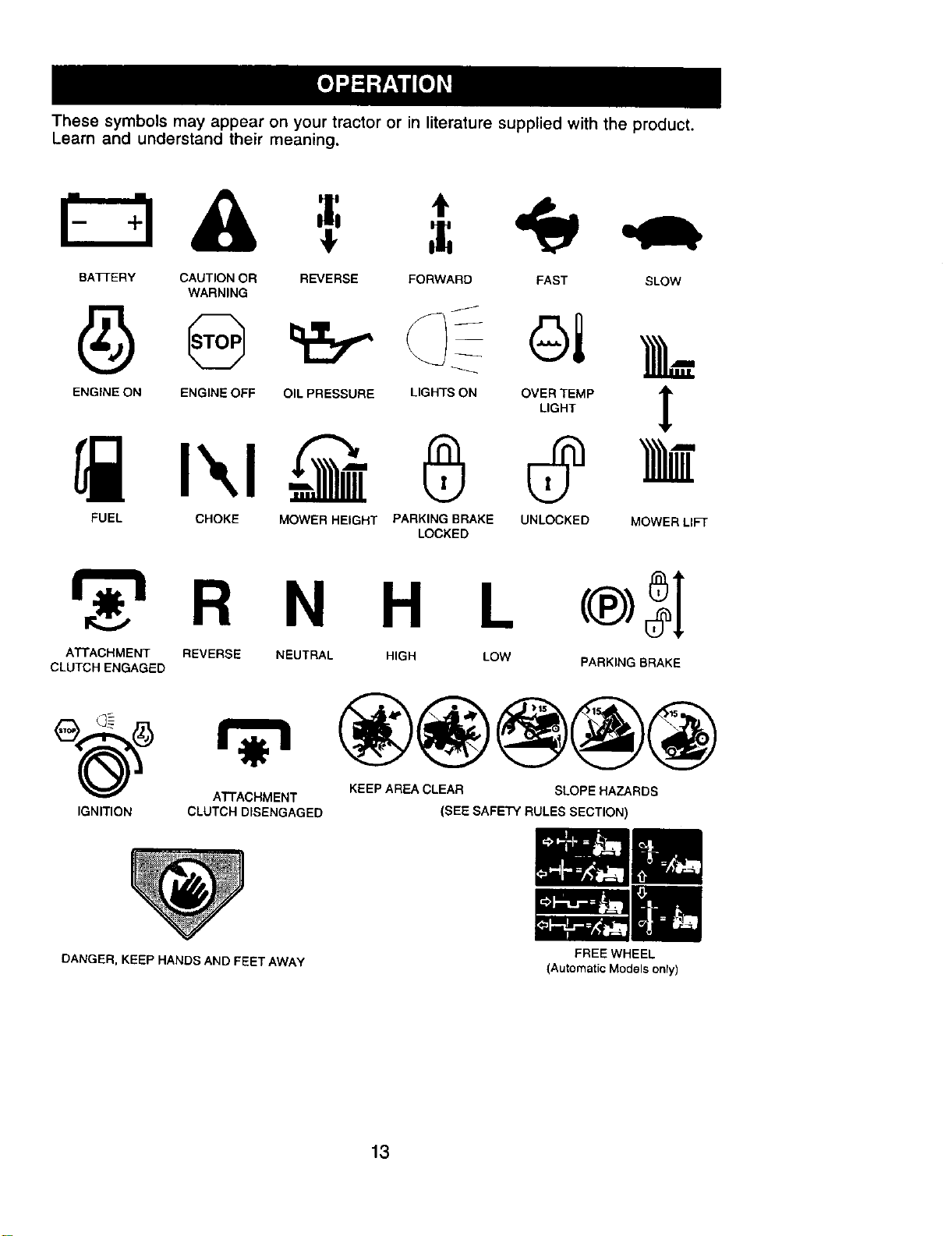
These symbols may appear on your tractor or in literature supplied with the product.
Learn and understand their meaning.
BA3q'ERY CAUTION OR REVERSE FORWARD FAST SLOW
WARNING
ENGINE ON ENGINE OFF OIL PRESSURE LIGHTS ON OVER TEMP
LIGHT
!
FUEL CHOKE MOWER HEIGHT PARKING BRAKE UNLOCKED MOWER LIFT
LOCKED
H L
ATTACHMENT REVERSE NEUTRAL HIGH LOW
CLUTCH ENGAGED
PARKING BRAKE
ATTACHMENT KEEP AREA CLEAR SLOPE HAZARDS
IGNITION CLUTCH DISENGAGED (SEE SAFETY RULES SECTION)
DANGER, KEEP HANDS AND FEET AWAY
FREE WHEEL
(Automatic Models only)
13
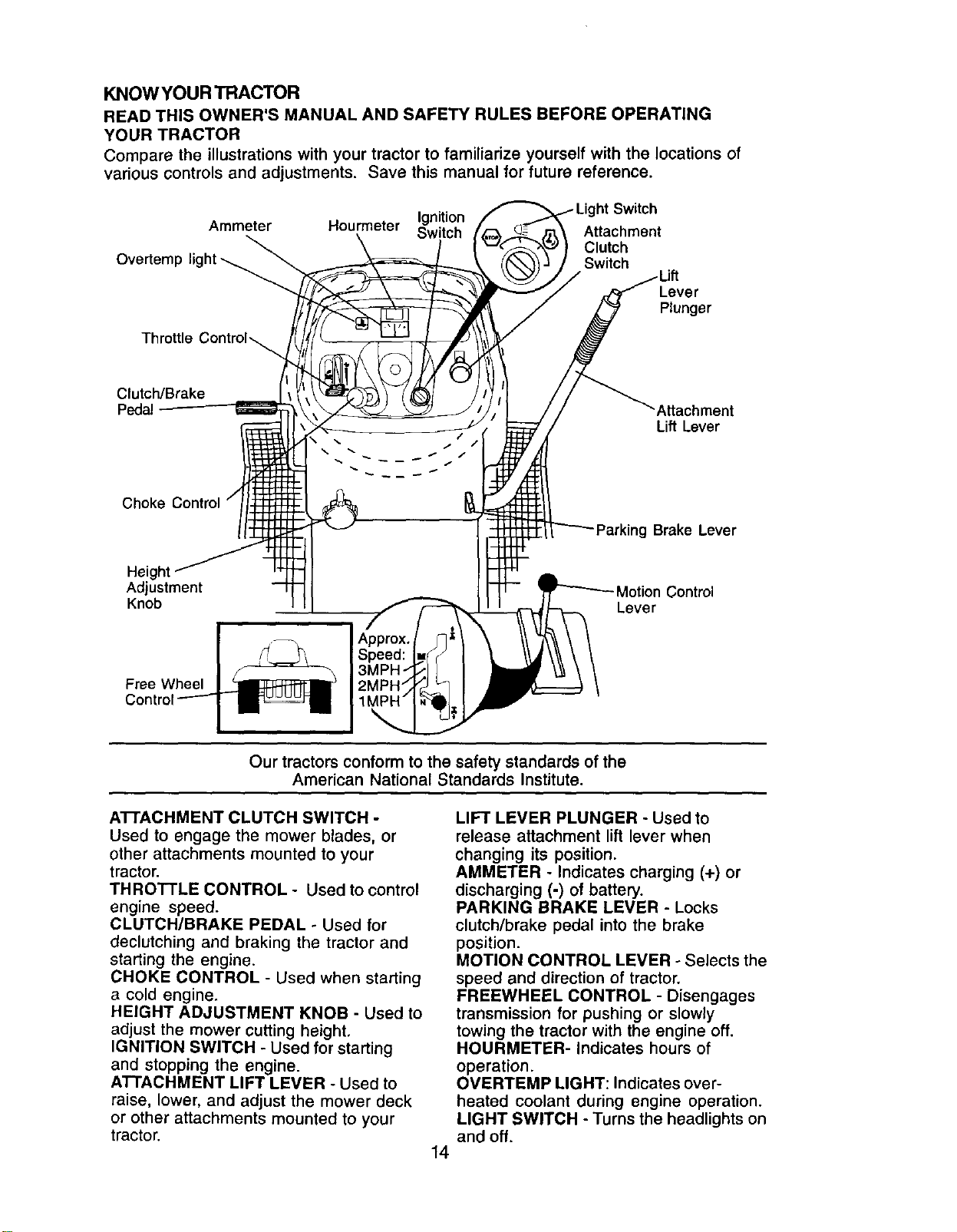
KNOWYOUR TRACTOR
READ THIS OWNER'S MANUAL AND SAFETY RULES BEFORE OPERATING
YOUR TRACTOR
Compare the illustrations with your tractor to familiarize yourself with the locations of
various controls and adjustments. Save this manual for future reference.
ht Switch
Ignition
Ammeter Hourmeter Switch Attachment
Clutch
Overtemp light_ Switch
Lever
Plunger
Throttle
Clutch/Brake
Pedal Attachment
Lift Lever
Choke Control
tg Brake Lever
Height
Adjustment
Knob
Free Wheel
Motion Control
Lever
Our tractors conform to the safety standards of the
American National Standards Institute.
A'n'ACHMENT CLUTCH SWITCH -
Used to engage the mower blades, or
other attachments mounted to your
tractor.
THROTTLE CONTROL - Used to control
engine speed.
CLUTCH/BRAKE PEDAL - Used for
declutching and braking the tractor and
starting the engine.
CHOKE CONTROL - Used when starting
a cold engine.
HEIGHT ADJUSTMENT KNOB - Used to
adjust the mower cutting height.
IGNITION SWITCH - Used for starting
and stopping the engine.
ATTACHMENT LIFT LEVER - Used to
raise, lower, and adjust the mower deck
or other attachments mounted to your
tractor.
14
LIFT LEVER PLUNGER - Used to
release attachment lift lever when
changing its position.
AMMETER - Indicates charging (+) or
discharging (-) of battery.
PARKING BRAKE LEVER - Locks
clutch/brake pedal into the brake
position.
MOTION CONTROL LEVER - Selects the
speed and direction of tractor.
FREEWHEEL CONTROL - Disengages
transmission for pushing or slowly
towing the tractor with the engine off.
HOURMETER- Indicates hours of
operation.
OVERTEMP LIGHT: Indicates over-
heated coolant during engine operation.
LIGHT SWITCH - Turns the headlights on
and off.
The operation of any tractor can result in foreign objects thrown into the
eyes, which can result in severe eye damage. Always wear safety glasses
or eye shields while operating your tractor or performing any adjustments
or repairs. We recommend a wide vision safety mask over spectacles or
standard safety glasses.
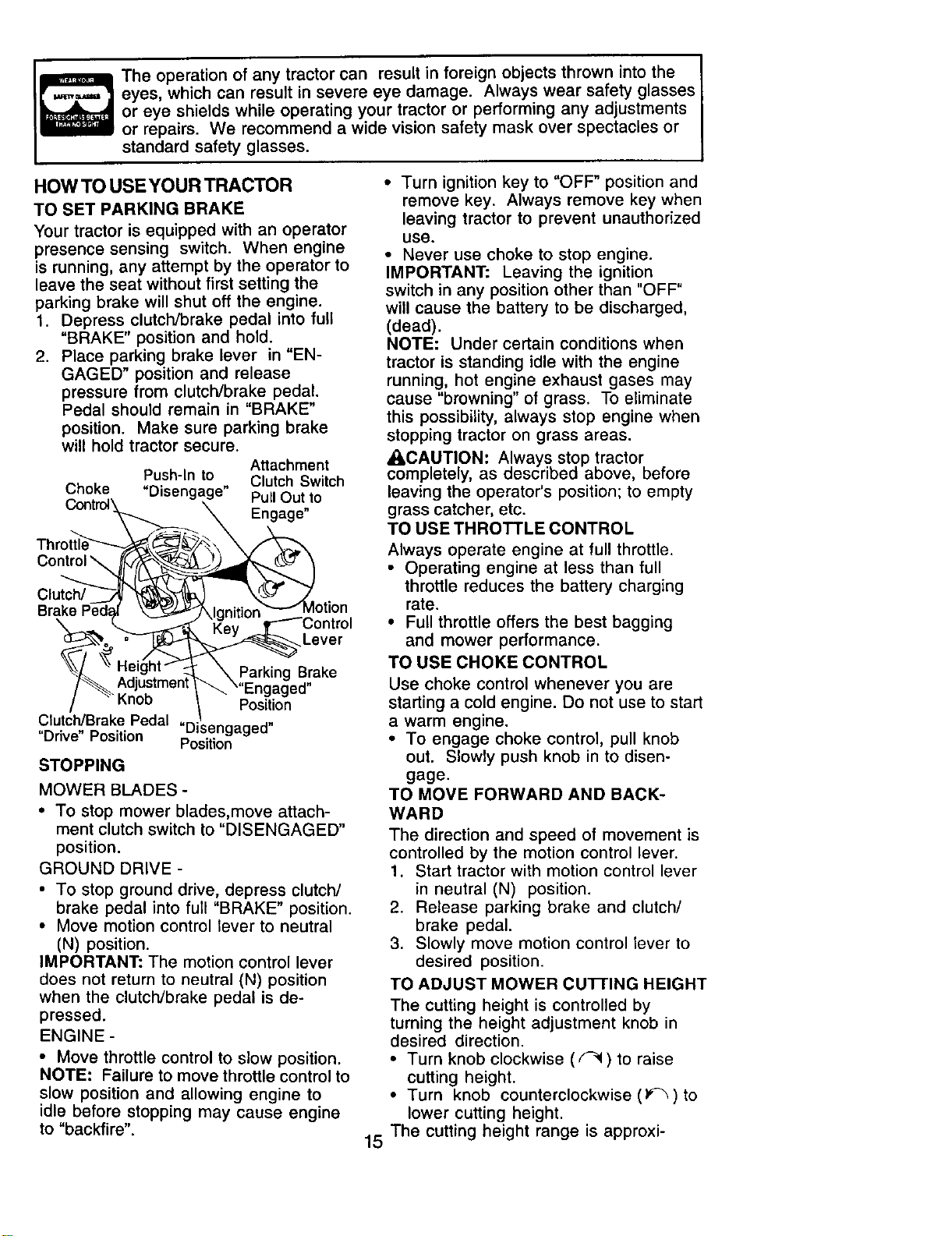
HOW TO USEYOUR TRACTOR
TO SET PARKING BRAKE
Your tractor is equipped with an operator
presence sensing switch. When engine
is running, any attempt by the operator to
leave the seat without first setting the
parking brake will shut off the engine.
1. Depress clutch/brake pedal into full
"BRAKE" position and hold.
2. Place parking brake lever in "EN-
GAGED" position and release
pressure from clutch/brake pedal.
Pedal should remain in "BRAKE"
position. Make sure parking brake
will hold tractor secure.
Attachment
Push-In to Clutch Switch
Choke "Disengage" Pull Out to
Cor_.trol_ _ Engage"
Throt__
Cont,ol
Innirinn _MOtiOn
Brak_._do=_'
" "_eY"-_---'_C-° ntr° I
_>_Lever
\ Parking Brake
Clutch/Brake Pedal "Disengaged"
"Drive" Position Position
STOPPING
MOWER BLADES -
° TO stop mower blades,move attach-
ment clutch switch to "DISENGAGED"
position.
GROUND DRIVE -
• To stop ground drive, depress clutch/
brake pedal into full "BRAKE" position.
• Move motion control lever to neutral
(N) position.
IMPORTANT: The motion control lever
does not return to neutral (N) position
when the clutch/brake pedal is de-
pressed.
ENGINE -
• Move throttle control to slow position.
NOTE: Failure to move throttle control to
slow position and allowing engine to
idle before stopping may cause engine
to "backfire".
• Turn ignition key to "OFF" position and
remove key. Always remove key when
leaving tractor to prevent unauthorized
use.
• Never use choke to stop engine.
IMPORTANT: Leaving the ignition
switch in any position other than "OFF"
will cause the battery to be discharged,
(dead).
NOTE: Under certain conditions when
tractor is standing idle with the engine
running, hot engine exhaust gases may
cause "browning" of grass. To eliminate
this possibility, always stop engine when
stopping tractor on grass areas.
A:_CAUTION: Always stop tractor
completely, as described above, before
leaving the operator's position; to empty
grass catcher, etc.
TO USE THROTTLE CONTROL
Always operate engine at full throttle.
• Operating engine at less than full
throttle reduces the battery charging
rate.
• Full throttle offers the best bagging
and mower performance.
TO USE CHOKE CONTROL
Use choke control whenever you are
starting a cold engine. Do not use to start
a warm engine.
• To engage choke control, pull knob
out. Slowly push knob in to disen-
gage.
TO MOVE FORWARD AND BACK-
WARD
The direction and speed of movement is
controlled by the motion control lever.
1. Start tractor with motion control lever
in neutral (N) position.
2. Release parking brake and clutch/
brake pedal.
3. Slowly move motion control lever to
desired position.
TO ADJUST MOWER CuI-rlNG HEIGHT
The cutting height is controlled by
turning the height adjustment knob in
desired direction.
• Turn knob clockwise (_) to raise
cutting height.
• Turn knob counterclockwise (1__) to
lower cutting height,
15 The cutting height range is approxi-
mately1-1/2"to 4". The heightsare
measuredfromthegroundto theblade
tipwiththeenginenotrunning.These
heightsare approximateandmayvary
dependinguponsoil conditions,height
ofgrassandtypesof grassbeing
mowed,
• The average lawn should be cut to
approximately 2-1/2 inches during the
cool season and to over 3 inches
during hot months. For healthier and
better looking lawns, mow often and
after moderate growth.
• For best cutting performance, grass
over 6 inches in height should be
mowed twice. Make the first cut
relatively high; the second to desired
height.
TO ADJUST GAUGE WHEELS
Gauge wheels are properly adjusted
when they are slightly off the ground
when mower is at the desired cutting
height in operating position. Gauge
wheels then keep the deck in proper
position to help prevent scalping in most
terrain conditions.
NOTE: Be sure tractor is on a flat level
surface.
1. Lower mower and adjust mower to
desired cutting height.
2. Remove retainer spring and clevis
pin which secure each gauge wheel
bar,
3. Lower gauge wheels to ground.
Raise gauge wheels slightly to align
holes in bracket and gauge wheel
bar and insert clevis pin. Gauge
wheels should be slightly off the
ground.
4. Replace retainer spring into clevis
pin.
5. Be sure all gauge wheels are in the
same setting.
IMPORTANT: Be sure to readjust gauge
wheels if you change the cutting height
of the mower deck.
Retainer
Clevis
: Pin
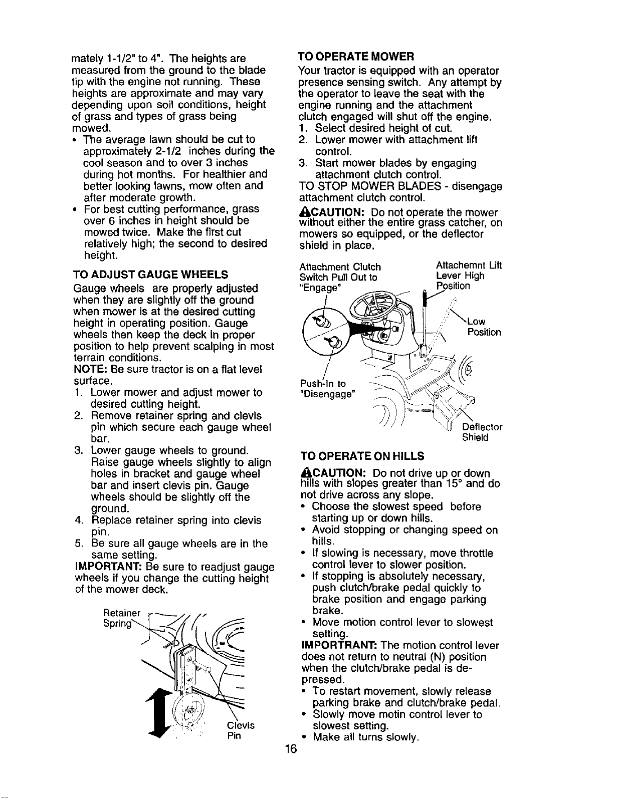
TO OPERATE MOWER
Your tractor is equipped with an operator
presence sensing switch. Any attempt by
the operator to leave the seat with the
engine running and the attachment
clutch engaged will shut off the engine.
1. Select desired height of cut.
2. Lower mower with attachment lift
control.
3. Start mower blades by engaging
attachment clutch control.
TO STOP MOWER BLADES - disengage
attachment clutch control.
_kCAUTION: Do not operate the mower
without either the entire grass catcher, on
mowers so equipped, or the deflector
shield in place,
Attachment Clutch
Switch Pull Out to
"Engage"
Attachemnt Lift
Lever High
Position
,ill%Low
Position
to
"Disengage" _
16
Deflector
Shield
TO OPERATE ON HILLS
_0_CAUTION: Do not drive up or down
hills with slopes greater than 15 ° and do
not ddve across any slope.
• Choose the slowest speed before
starting up or down hills.
• Avoid stopping or changing speed on
hills.
• If slowing is necessary, move throttle
control lever to slower position.
• If stopping is absolutely necessary,
push clutch/brake pedal quickly to
brake position and engage parking
brake.
• Move motion control lever to slowest
setting.
IMPORTRANT: The motion control lever
does not return to neutral (N) position
when the clutch/brake pedal is de-
pressed.
• To restart movement, slowly release
parking brake and clutch/brake pedal.
• Slowly move motin control lever to
slowest setting.
• Make all turns slowly.
TOTRANSPORT
When pushing or towing your tractor, be
sure to disengage transmission by
placing freewheel control in freewheel-
ing position. Free wheel control is
located at the rear drawbar of tractor.
1. Raise attachment lift to highest
position with attachment lift control.
2. Remove retainer spring from free-
wheel control rod.
3. Push control rod in to disengage
transmission and reinsert retainer
spring into control rod hole now on
back side of the bracket.
• Do not push or tow tractor at more
than two (2) MPH.
• To reengage transmission, reverse
above procedure.
NOTE: To protect hood from damage
when transporting your tractor on a truck
or a trailer, be sure hood is closed and
secured to tractor. Use an appropriate
means of tying hood to tractor (rope,
cord, etc.).
TOWING CARTS AND OTHER AT-
TACHMENTS
Tow only the attachments that are
recommended by and comply with
specifications of the manufacturer of your
tractor. Use common sense when towing.
Too heavy of a load, while on a slope, is
dangerous. ]]res can lose traction with
the ground and cause you to lose control
of your tractor.
BEFORE STARTING THE ENGINE
CHECK ENGINE OIL LEVEL
The engine in your tractor has been
shipped, from the factory, already filled
with summer weight oil.
1. Check engine oil with tractor on level
ground.
2. Unthread and remove oil fill cap/
dipstick; wipe oil off. Reinsert the
dipstick into the tube and rest oil fill
cap on the tube. Do not thread the
cap onto the tube. Remove and read
oil level, if necessary, add oil until
"FULL" mark on dipstick is reached.
Do not overfill.
• For cold weather operation you should
change oil for easier starting (See "OIL
VISCOSITY CHART" in the Mainte-
nance section of this manual).
• To change engine oil, see the Mainte-
nance section in this manual.
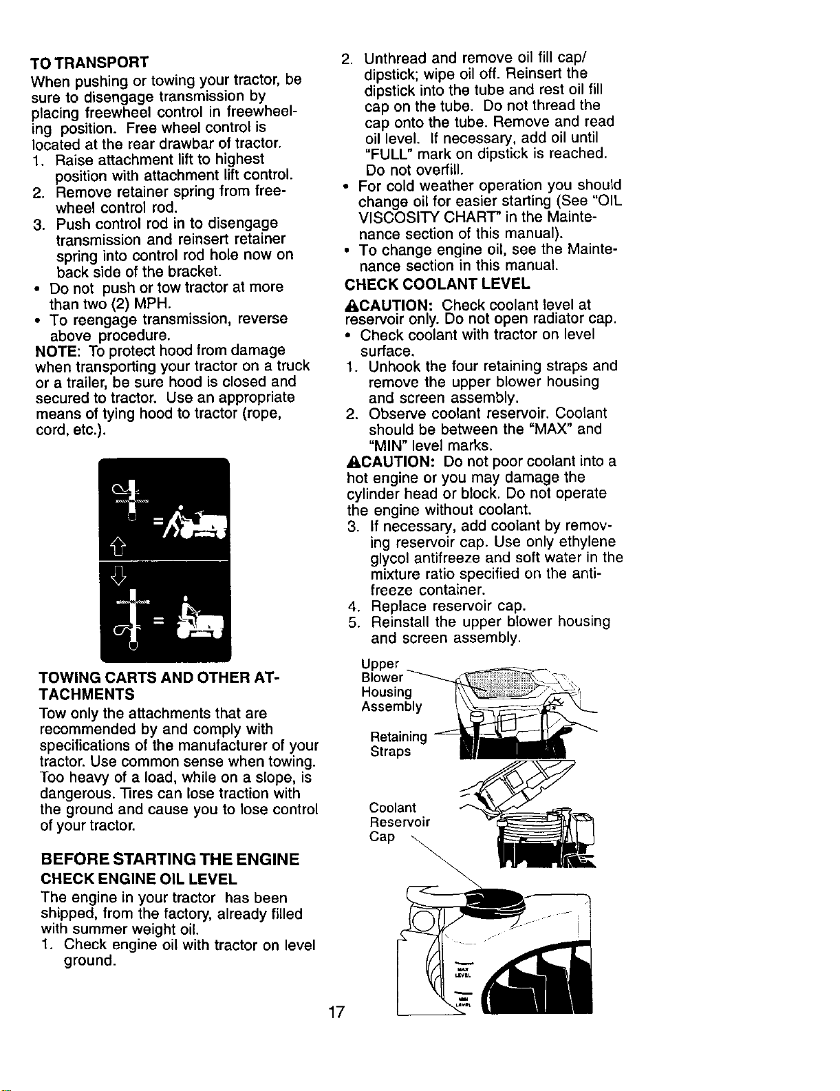
CHECK COOLANT LEVEL
ACAUTION: Check coolant level at
reservoir only. Do not open radiator cap.
• Check coolant with tractor on level
surface.
1. Unhook the four retaining straps and
remove the upper blower housing
and screen assembly.
2. Observe coolant reservoir. Coolant
should be between the "MAX" and
"MIN" level marks.
ACAUTION: Do not poor coolant into a
hot engine or you may damage the
cylinder head or block. Do not operate
the engine without coolant.
3. If necessary, add coolant by remov-
ing reservoir cap. Use only ethylene
glycol antifreeze and soft water in the
mixture ratio specified on the anti-
freeze container.
4. Replace reservoir cap.
5. Reinstall the upper blower housing
and screen assembly.
Upper
Housing
Assembly
Retaining
Straps
17
Coolant
Reservoir
Cap _
ADD GASOLINE
• Fillfuel tank. Use fresh, clean, regular
unleaded gasoline with a minimum of 87
octane. (Use of leaded gasoline will
increase carbon and lead oxide deposits
and reduce valve life). Do not mix oilwith
gasoline. Purchase fuel in quantities that
can be used within 30 days to assure fuel
freshness.
IMPORTANT: When operating in tempera-
tures below 32°F(0°C), use fresh, clean
winter grade gasoline to help insure good
cold weather starting.
_I=WARNING: Experience indicates that
alcohol blended fuels (called gasohol or
using ethanol or methanol) can attract
moisture which leads to separation and
formation of acids during storage. Acidic gas
can damage the fuel system of an engine
while in storage. To avoid engine problems,
the fuel system should be emptied before
storage of 30 days or longer. Drain the gas
tank, start the engine and let it run until the
fuel lines and carburetor are empty. Use
fresh fuel next season. See Storage
Instructions for additional information. Never
use engine or carburetor cleaner products in
the fuel tank or permanent damage may
occur.
_CAUTION: Fill to bottom of gas tank filler
neck. Do not overfill. Wipe off any spilled oil
or fuel. Do not store, spill or use gasoline
near an open flame.
OVERTEMP UGHT
Located on the dash of your tractor, this light
alerts you to the engine being overheated
which requires immediate attention.
• Ught should come on when engine is not
running and the key switch is in 'IDN"
position, this is a test to be sure the light is
working.
• If light comes on while operating the
engine, stop the engine. Find and correct
the problem. See "Engine Overheats" in
the Trouble Shooting
section of this manual.
TO START ENGINE
When starting the engine for the first time or if
the engine has run out of fuel, it willtake
extra cranking time to move fuel from the
tank to the engine.
1. Be sure freewheel control is in the
transmission engaged position.
2. Sit on seat in operating position, depress
clutch/brake pedal and set parking
brake.
3. Place motion control lever in neutral (N)
position.
4. Move attachment clutch to "DISEN-
GAGED" position.
5. Move throttle control to fast position
6. Pull choke control out for a cold engine
start attempt. For a warm engine start
attempt the choke control may not be
needed.
NOTE: Before starting, read the warm and
cold starting procedures below.
7. Insert key into ignitionand turn key
clockwise to "START" position and
release key as soon as engine starts. Do
not run starter continuously for more than
fifteen seconds per minute. If the engine
does not start after several attempts,
push choke control in, wait a few minutes
and try again. If engine still does not start,
pull the choke control out and retry.
WARM WEATHER STARTING (50° Fand
above)
8. When enginestarts,slowlypushchoke
control in untilthe enginebegins to run
smoothly.Ifthe enginestartsto run
roughly,pullthe choke control outslightly
for a few secondsandthen continue to
push the controlinslowly.
* The attachments and ground drive can
now be used. If the engine does not
accept the load, restart the engine and
allow itto warm up for one minute
using the choke as described above.
COLD WEATHER STARTING (50° F and
below)
8. When engine starts, slowly push choke
control in until the engine begins to run
smoothly. Continue to push the choke
control in small steps allowing the
engine to accept small changes in
speed and load, until the choke control is
fully in. Ifthe engine starts to run roughly,
pull the choke control out slightlyfor a
few seconds and then continue to push
the control in slowly. This may require an
engine warm-up period from several
seconds to several minutes, depending
on the temperature.
AUTOMATIC TRANSMISSION WARM UP
Before driving the unit in cold weather, the
transmission should be warmed up as
follows:
1. Be sure the tractor is on level ground.
2. Place the motion control lever in neutral.
Release the parking brake and let the
clutch/brake slowly retum to operating
position.
3. Allow one minute for transmission to
warm up. This can be done during the
engine warm up period.
18
• The attachments can be used during the
engine warm-up period after the transmis-
sion has been warmed up and may
require the choke control be pulled out
slightly.
NOTE: If at a high altitude (above 3000 feet)
or in cold temperatures (below 32 F) the
carburetor fuel mixture may need to be
adjusted for best engine performance. See
"TO ADJUST CARBURETOR" in the
Service and Adjustments section of this
manual.
PURGE TRANSMISSION
_CAUTION: Never engage or disengage
freewheel lever while the engine is running.
To ensure proper operation and perfor-
mance, itis recommended that the transmis-
sion be purged before operating tractor for
the first time. This procedure will remove any
trapped air inside the transmission which
may have developed during shipping of
your tractor.
IMPORTANT: Should your transmission
require removal for service or replacement, it
should be purged after reinstallation before
operating the tractor.
1. Place tractor safely on level surface
with engine off and parking brake set.
2. Disengage transmission by placing
freewheel control in freewheeling
position (See "TO TRANSPORT" in
this section of manual).
3. Sitting in the tractor seat, start engine.
After the engine is running, move
throttle control to slow position. With
motion control lever in neutral (N)
position, slowly disengage clutch/
brake pedal.
4. Move motion control lever to full
forward position and hold for five (5)
seconds. Move lever to full reverse
position and hold for five (5) seconds.
Repeat this procedure three (3)
times.
NOTE: During this procedure there will be
no movement of drive wheels. The air is
being removed from hydraulic drive system.
5. Move motion control lever to neutral
(N) position. Shut- off engine and set
parking brake.
6. Engage transmission by placing
freewheel control in driving position
(See "TO TRANSPORT" in this
section of manual).
7. Sitting in the tractor seat, start
engine. After the engine is running,
move throttle control to half (1/2)
speed. With motion control lever in
neutral (N) position, slowly disen-
gage clutch/brake pedal.
8. Slowly move motion control lever
forward, after the tractor moves
approximately five (5) feet, slowly
move motion control lever to reverse
position. After the tractor moves
approximately five (5) feet return the
motion control lever to the neutral (N)
position. Repeat this procedure with
the motion control lever three (3)
times.
Your tractor is now purged and now
ready for normal operation.
MOWING TIPS
• Tire chains cannot be used when the
mower housing is attached to tractor.
• Mower should be properly leveled for best
mowing performance. See "TO LEVEL
MOWER HOUSING" in the Service and
Adjustments section of this manual.
• The left hand side of mower should be
used for trimming.
• Drive so that clippings are discharged
onto the area that has been cut. Have the
cut area to the right of the tractor. This will
result in a more even distribution of
clippings and more uniform cutting.
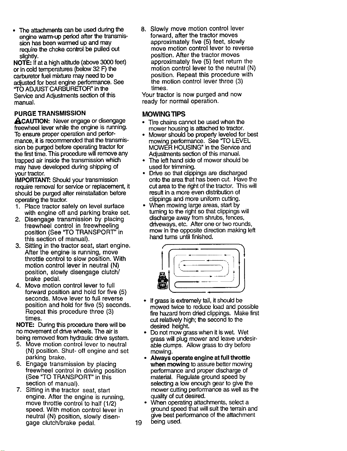
• When mowing large areas, start by
turning to the right so that clippings will
discharge away from shrubs, fences,
driveways, etc. After one or two rounds,
mow in the opposite direction making left
hand turns until finished.
f
it;
/
• If grass is extremely tall, it should be
mowed twice to reduce load and possible
fire hazard from dried clippings. Make first
cut relatively high; the second to the
desired height.
• Do not mew grass when it is wet. Wet
grass will plug mower and leave undesir-
able clumps. Allow grass to dry before
mowing.
• Always operate engine at full throttle
when mowing to assure better mowing
performance and proper discharge of
material. Regulate ground speed by
selecting a low enough gear to give the
mower cutting performance as well as the
quality of cut desired.
• When operating attachments, select a
ground speed that will suit the terrain and
give best performance of the attachment
19 being used.
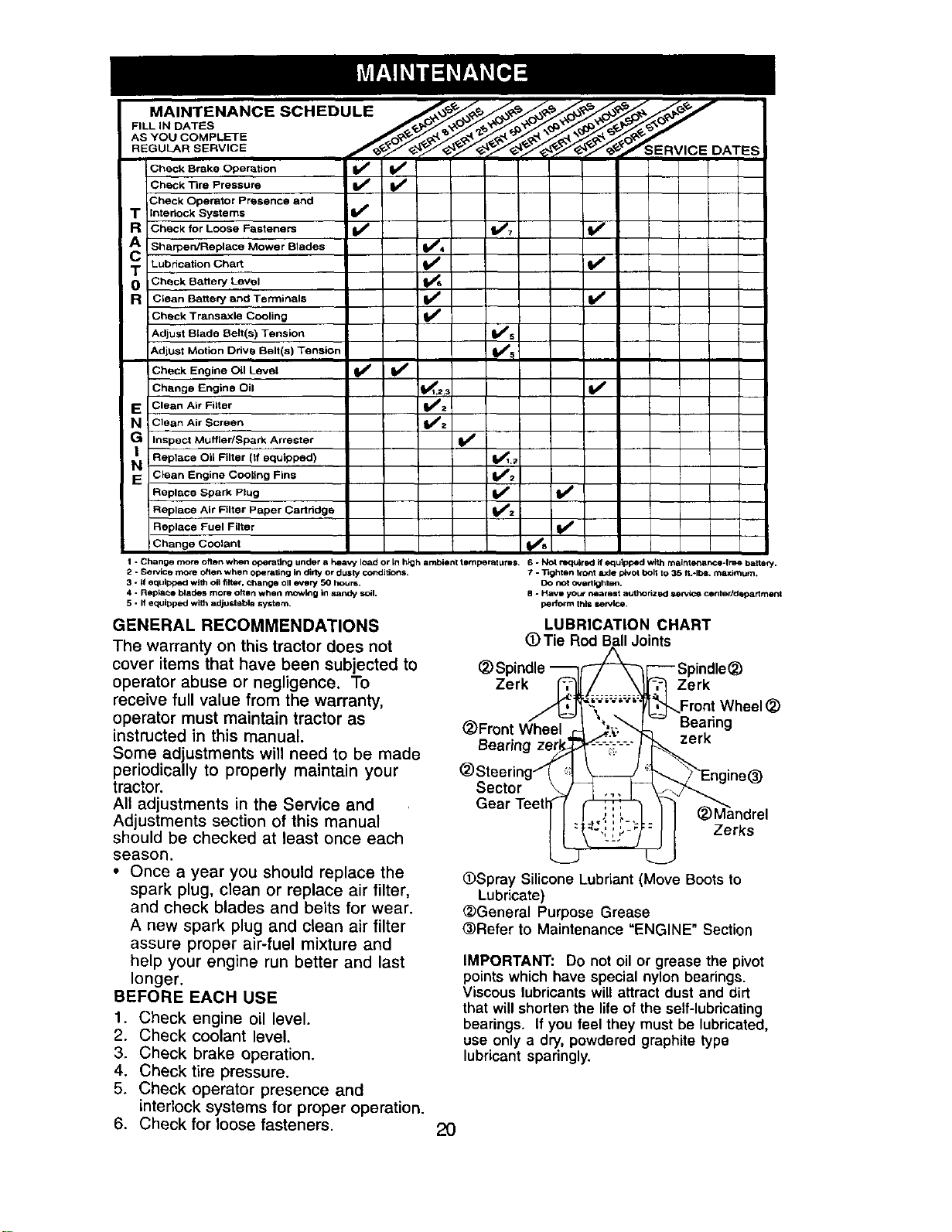
MAINTENANCE SCHEDULE
FILL IN DATES
AS YOU COMPLETE
REGULAR SERVICE SERVICE
Check Srake Oper_ti°n _ _
Check Tire Pressure
iCheck Operator Presence and
T ;nteriock Systems If
R Check for Loose Fasteners V* V'7 If
AC Sharpen/Replace Mower Blades _4
T Lubrication Chart I If
0 I Check Battery Level
R Clean Battery and Terminals li_
Check Transaxle Cooling V'
Adjust Blade Belt(s) Tension I_s
Adjust Motion Drive Belt(s) Tension V's
Check Engine Oil Level If If
Change Engine Oil 1_,_3 If
E Clean AIr Filter _V':
N Clean Air Screen
v"
G inspect Muffler/Spark Arrester
N Replace Oil Filter (if equipped) Vl.=
Clean Engine Cooling Fins VW=
Replace Spark Plug _2 V*
i
Replace Air Filter Paper Cartridge I
Replace Fuel Filter V'
i
Change Coolant Ks
1 - Change more often when operating under a hea W load or In high ambient temperatures. 6 - Not re'q_lr ed if equipl:_d with mainte_ance-tme batte_.
2 * Service more often when operating In di_' or dusly condi_orts. 7 - 33ghten 1rent axle I_VOt bolt to 35 II.*lb_. maximum.
3 ° if equipped with oil filter, change oll every 50 hours. DO not overtightsn.
4 - Rep_e blades more often when mowing In sandy soil. 8 ° Havi you# nearelt a_'the riz_KISeP*_Ce center/deparlmerd
5 - If equipped with adjustsbl8 system, perform th_i service.
GENERAL RECOMMENDATIONS
The warranty on this tractor does not
cover items that have been subjected to
operator abuse or negligence. To
receive full value from the warranty,
operator must maintain tractor as
instructed in this manual.
Some adjustments will need to be made
periodically to properly maintain your
tractor.
All adjustments in the Service and
Adjustments section of this manual
should be checked at least once each
season.
• Once a year you should replace the
spark plug, clean or replace air filter,
and check blades and belts for wear.
A new spark plug and clean air filter
assure proper air-fuel mixture and
help your engine run better and last
longer.
BEFORE EACH USE
1. Check engine oil level.
2. Check coolant level.
3. Check brake operation.
4. Check tire pressure.
5. Check operator presence and
interlock systems for proper operation.
6. Check for loose fasteners.
LUBRICATION CHART
(D Tie Rod Ball Joints
_)Spindle _ _Z_L'_-- Spindle(_)
l ........ --_-'-1 Zerk
Zerk_ "_.... _ ,_._Front Wheel _)
(_)Front Wheel '_,-._ I_ Bearing
Bearing zerl
(_)Steering-'_ _ii_)-'-'_r k
Sector \ _ne_
Gear Teetl_ ..,: i __,1 I I (2JMandrel
Zerks
(_Spray Silicone Lubnant (Move Boots to
Lubricate)
_General Purpose Grease
@Refer to Maintenance "ENGINE" Section
IMPORTANT: Do not oil or grease the pivot
points which have special nylon bearings.
Viscous lubricants will attract dust and dirt
that will shorten the life of the self-lubricating
bearings. If you feel they must be lubricated,
use only a dry, powdered graphite type
lubricant sparingly.
2O
TRACTOR
Always observe safety rules when
performing any maintenance.
BRAKE OPERATION
If tractor requires more than six (6) feet
stopping distance at high speed in
highest gear, then brake must be
adjusted. (See "TO ADJUST BRAKE" in
the Service and Adjustments section of
this manual).
TIRES
• Maintain proper air pressure in all tires
(See =PRODUCT SPECIFICATIONS"
section of this manual).
• Keep tires free of gasoline, oil, or
insect control chemicals which can
harm rubber.
• Avoid stumps, stones, deep ruts, sharp
objects and other hazards that may
cause tire damage.
NOTE: To seal tire punctures and
prevent flat tires due to slow leaks, tire
sealant may be purchased from your
local parts dealer. Tire sealant also
prevents tire dry rot and corrosion.
OPERATOR PRESENCE SYSTEM
Be sure operator presence and interlock
systems are working properly. If your
tractor does not function as described,
repair the problem immediately.
• The engine should not start unless the
clutch/brake pedal is fully depressed
and attachement clutch control is in
the disengaged position.
• When the engine is running, any
attempt by the operator to leave the
seat without first setting the parking
brake should shut off the engine.
• When the engine is running and the
attachment clutch is engaged, any
attempt by the operator to leave the
seat should shut off the engine.
• The attachment clutch should never
operate unless the operator is in the
seat.
BLADE CARE
For best results mower blades must be
kept sharp. Replace bent or damaged
blades.
BLADE REMOVAL
1. Raise mower to highest position to
allow access to blades.
NOTE: Protect your hands with gloves
and/or wrap blade with heavy cloth.
2. Remove blade bolt by turning
counterclockwise.
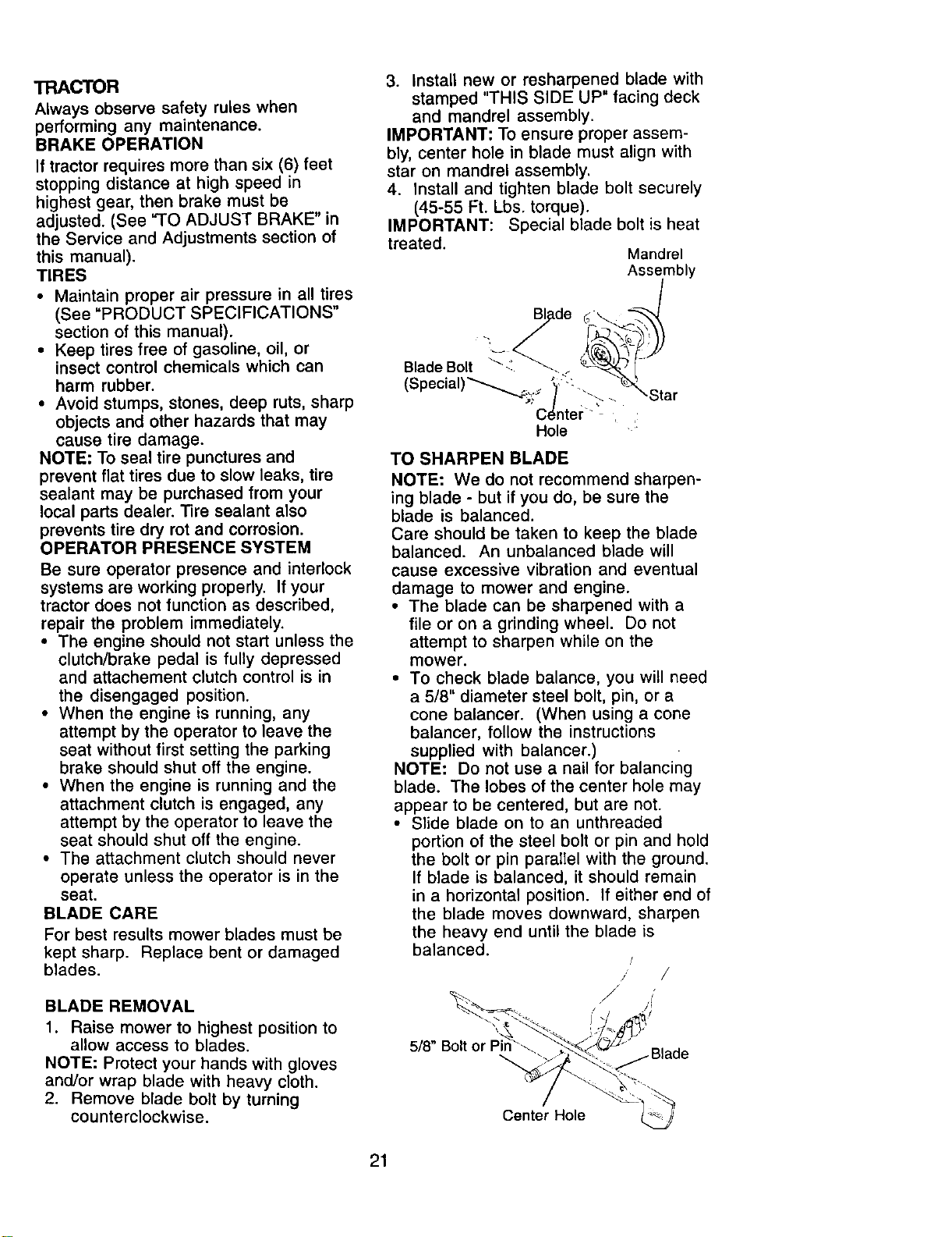
3. Install new or resharpened blade with
stamped "THIS SIDE UP" facing deck
and mandrel assembly.
IMPORTANT: To ensure proper assem-
bly, center hole in blade must align with
star on mandrel assembly.
4. Install and tighten blade bolt securely
(45-55 Ft. Lbs. torque).
IMPORTANT: Special blade bolt is heat
treated.
Mandrel
Assembly
g de ;
Blade Bolt :. __ _ [
(Special)"_'_2S °)' <'.'-_ __'_Star
•Center._ . :
Hole
TO SHARPEN BLADE
NOTE: We do not recommend sharpen-
ing blade - but if you do, be sure the
blade is balanced.
Care should be taken to keep the blade
balanced. An unbalanced blade will
cause excessive vibration and eventual
damage to mower and engine.
• The blade can be sharpened with a
file or on a grinding wheel. Do not
attempt to sharpen white on the
mower.
• To check blade balance, you will need
a 5/8" diameter steel bolt, pin, or a
cone balancer. (When using a cone
balancer, follow the instructions
supplied with balancer.)
NOTE: Do not use a nail for balancing
blade. The lobes of the center hole may
appear to be centered, but are not.
• Slide blade on to an unthreaded
portion of the steel bolt or pin and hold
the bolt or pin parallel with the ground.
If blade is balanced, it should remain
in a horizontal position. If either end of
the blade moves downward, sharpen
the heavy end until the blade is
balanced.
/
j /
j' •
5/8" Bolt
Center Hole
21
BATTERY
Your tractor has a battery charging
system which is sufficient for normal use.
However, periodic charging of the battery
with an automotive charger will extend
its life.
• Keep battery and terminals clean.
• Keep battery bolts tight.
• Keep small vent holes open.
• Recharge at 6-10 amperes for 1 hour.
NOTE: The original equipment battery on
your tractor is maintenance free. Do not
attempt to open or remove caps or
covers. Adding or checking level of
electrolyte is not necessary.
TO CLEAN BATTERY AND TERMINALS
Corrosion and dirt on the battery and
terminals can cause the battery to "leak"
power.
1. Remove terminal guard.
2. Disconnect BLACK battery cable first
then RED battery cable and remove
battery from tractor.
3. Rinse the battery with plain water and
dry.
4. Clean terminals and battery cable
ends with wire brush until bright.
5. Coat terminals with grease or
petroleum jelly.
6. Reinstall battery (See "REPLACING
BAI-rERY" in the SERVICE AND
ADJUSTMENTS section of this
manual).
V-BELTS
Check V-belts for deterioration and wear
after 100 hours of operation and replace
if necessary. The belts are not adjustable.
Replace belts if they begin to slip from
wear.
TRANSAXLE COOLING
The transmission fan and cooling fins
should be kept clean to assure proper
cooling.
Do not attempt to clean fan or transmis-
sion while engine is running or while the
transmission is hot. To prevent possible
damage to seals, do not use high
pressure water or steam to clean
transaxle.
• Inspect cooling fan to be sure fan
blades are intact and clean.
• Inspect cooling fins for dirt, grass
clippings and other materials. To
prevent damage to seals, do not use
compressed air or high pressure
sprayer to clean cooling fins.
TRANSAXLE PUMP FLUID
The transaxle was sealed at the factory
and fluid maintenance is not required for
the life of the transaxle. Should the
transaxle ever leak or require servicing,
contact your nearest authorized service
center/department.
ENGINE
LUBRICATION
Only use high quality detergent oil rated
with API service classification SF-SJ.
Select the oil's SAE viscosity grade
according to your expected operating
temperature.
Change the oil after every 50 hours of
operation or at least once a year if the
tractor is not used for 50 hours in one
year.
Check the crankcase oil level before
starting the engine and after each eight
(8) hours of operation. Tighten oil fill cap/
dipstick securely each time you check
the oil level.
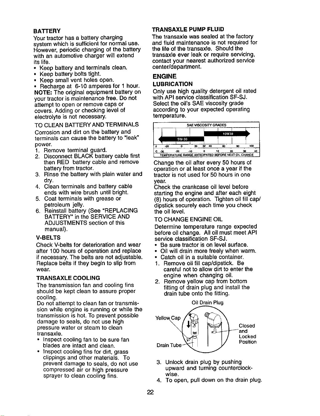
TO CHANGE ENGINE OIL
Determine temperature range expected
before oil change. All oil must meet API
service classification SF-SJ.
• Be sure tractor is on level surface.
• Oil will drain more freely when warm.
• Catch oil in a suitable container.
1. Remove oil fill cap/dipstick. Be
careful not to allow dirt to enter the
engine when changing oil.
2. Remove yellow cap from bottom
fitting of drain plug and install the
drain tube onto the fitting.
Oil Drain Plug
¥e,,ow ap
I '11'1_ _ _ Closed
[_1 I_ and
I I/ Locked
Drain Tube_._ Position
3. Unlock drain plug by pushing
upward and turning counterclock-
wise.
4. To open, pull down on the drain plug.
22
5. After oil has drained completely,
close and lock the drain plug by
pushing upward and turning clock-
wise until the pin is in the locked
position as shown.
6. Remove the drain tube and replace
the cap onto to the bottom fitting of
the drain plug.
7. Refill engine with oil through oil fill
dipstick tube. Pour slowly. Do not
overfill. For approximate capacity
see "PRODUCT SPECIFICATIONS"
section of this manual.
8. Use gauge on oil fill cap/dipstick for
checking level. Insert dipstick into the
tube and rest the oil fill cap on the
tube. Do not thread the cap onto the
tube when taking reading. Keep oil
at "FULL" line on dipstick. Tighten
cap onto the tube securely when
finished.
ENGINE OIL FILTER
Replace the engine oil filter every
season or every other oil change if the
tractor is used more than 100 hours in
one year.
AIR FILTER
Your engine will not run properly using a
dirty air filter. Clean the foam pre-cleaner
after every 25 hours of operation or
every season. Service paper cartridge
every 100 hours of operation or every
season, whichever occurs first.
Service air cleaner more often under
dusty conditions.
1. Unhook the four retaining straps and
remove the upper blower housing
and screen assembly.
TO SERVICE PRE-CLEANER
2. Slide foam pre-cleaner off cartridge.
3. Wash it in liquid detergent and water.
4. Squeeze it dry in a clean cloth. Allow
it to dry.
5 Saturate it in engine oil. Wrap it in
clean, absorbent cloth and squeeze
to remove excess oil.
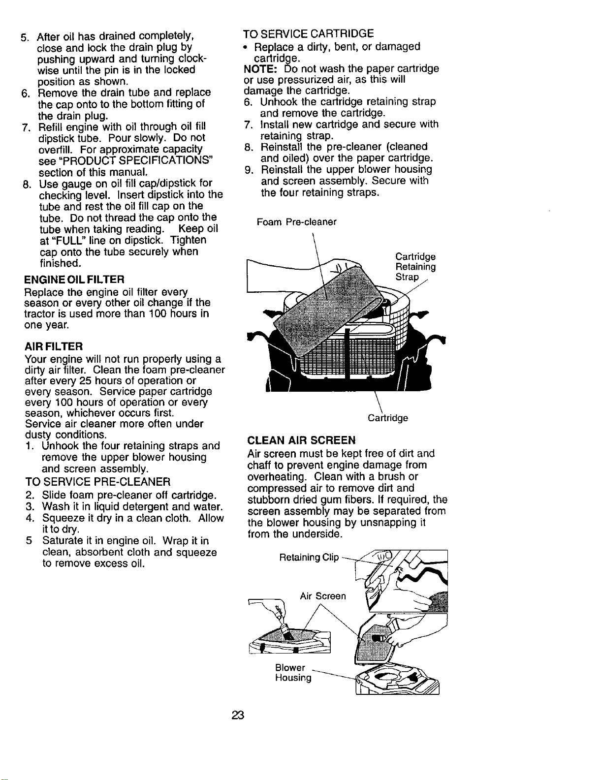
TO SERVICE CARTRIDGE
• Replace a dirty, bent, or damaged
cartridge.
NOTE: Do not wash the paper cartridge
or use pressurized air, as this will
damage the cartridge.
6. Unhook the cartridge retaining strap
and remove the cartridge.
7. Install new cartridge and secure with
retaining strap.
8. Reinstall the pre-cleaner (cleaned
and oiled) over the paper cartridge.
9. Reinstall the upper blower housing
and screen assembly. Secure with
the four retaining straps.
Foam Pre-cleaner
Cartridge
Retaining
Strap
Cartridge
CLEAN AIR SCREEN
Air screen must be kept free of dirt and
chaff to prevent engine damage from
overheating. Clean with a brush or
compressed air to remove dirt and
stubborn dried gum fibers. If required, the
screen assembly may be separated from
the blower housing by unsnapping it
from the underside.
Retainin(
Air Screen
Blower
Housing _
23
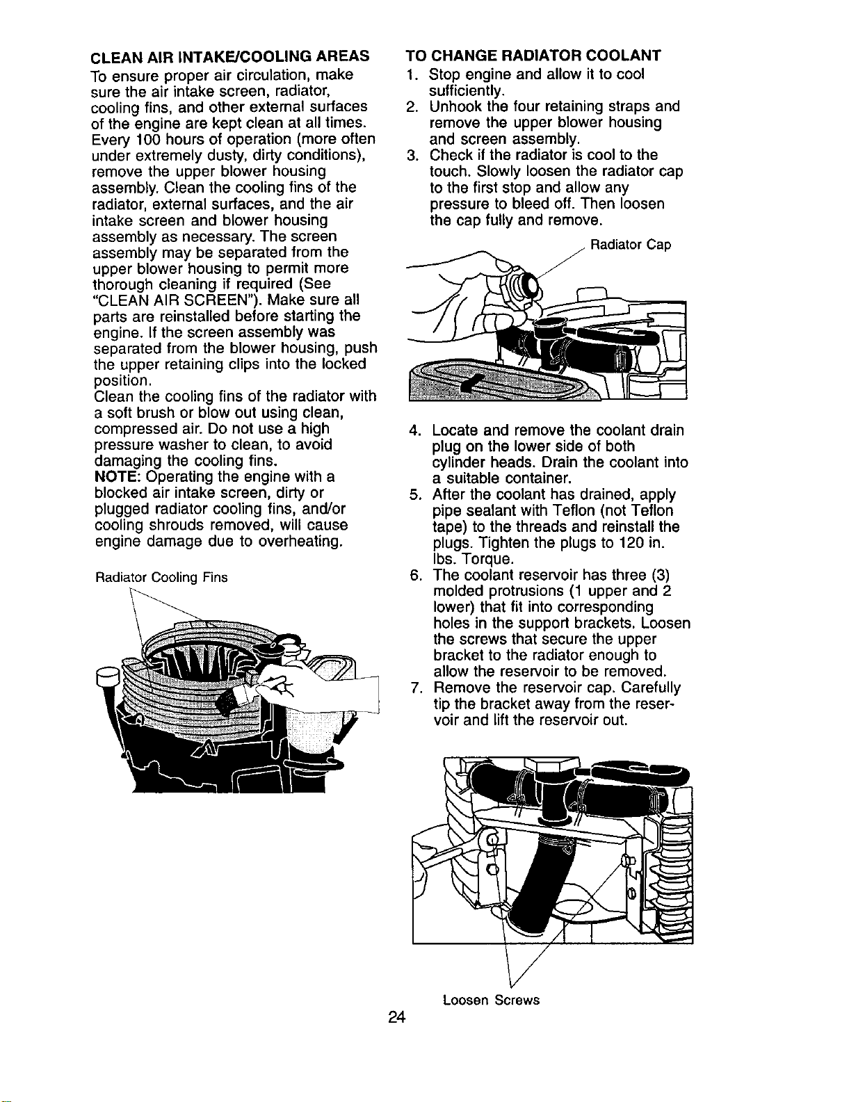
CLEAN AIR iNTAKE/COOLING AREAS
To ensure proper air circulation, make
sure the air intake screen, radiator,
cooling fins, and other external surfaces
of the engine are kept clean at all times.
Every 100 hours of operation (more often
under extremely dusty, dirty conditions),
remove the upper blower housing
assembly. Clean the cooling fins of the
radiator, external surfaces, and the air
intake screen and blower housing
assembly as necessary. The screen
assembly may be separated from the
upper blower housing to permit more
thorough cleaning if required (See
"CLEAN AIR SCREEN"). Make sure all
parts are reinstalled before starting the
engine. If the screen assembly was
separated from the blower housing, push
the upper retaining clips into the locked
position.
Clean the cooling fins of the radiator with
a soft brush or blow out using clean,
compressed air. Do not use a high
pressure washer to clean, to avoid
damaging the cooling fins.
NOTE: Operating the engine with a
blocked air intake screen, dirty or
plugged radiator cooling fins, and/or
cooling shrouds removed, will cause
engine damage due to overheating.
Radiator Cooling Fins
TO CHANGE RADIATOR COOLANT
1. Stop engine and allow it to cool
sufficiently.
2. Unhook the four retaining straps and
remove the upper blower housing
and screen assembly.
3. Check if the radiator is cool to the
touch. Slowly loosen the radiator cap
to the first stop and allow any
pressure to bleed off. Then loosen
the cap fully and remove.
Radiator Cap
4. Locate and remove the coolant drain
plug on the lower side of both
cylinder heads. Drain the coolant into
a suitable container.
5. After the coolant has drained, apply
pipe sealant with Teflon (not Teflon
tape) to the threads and reinstall the
plugs. Tighten the plugs to 120 in.
Ibs. Torque.
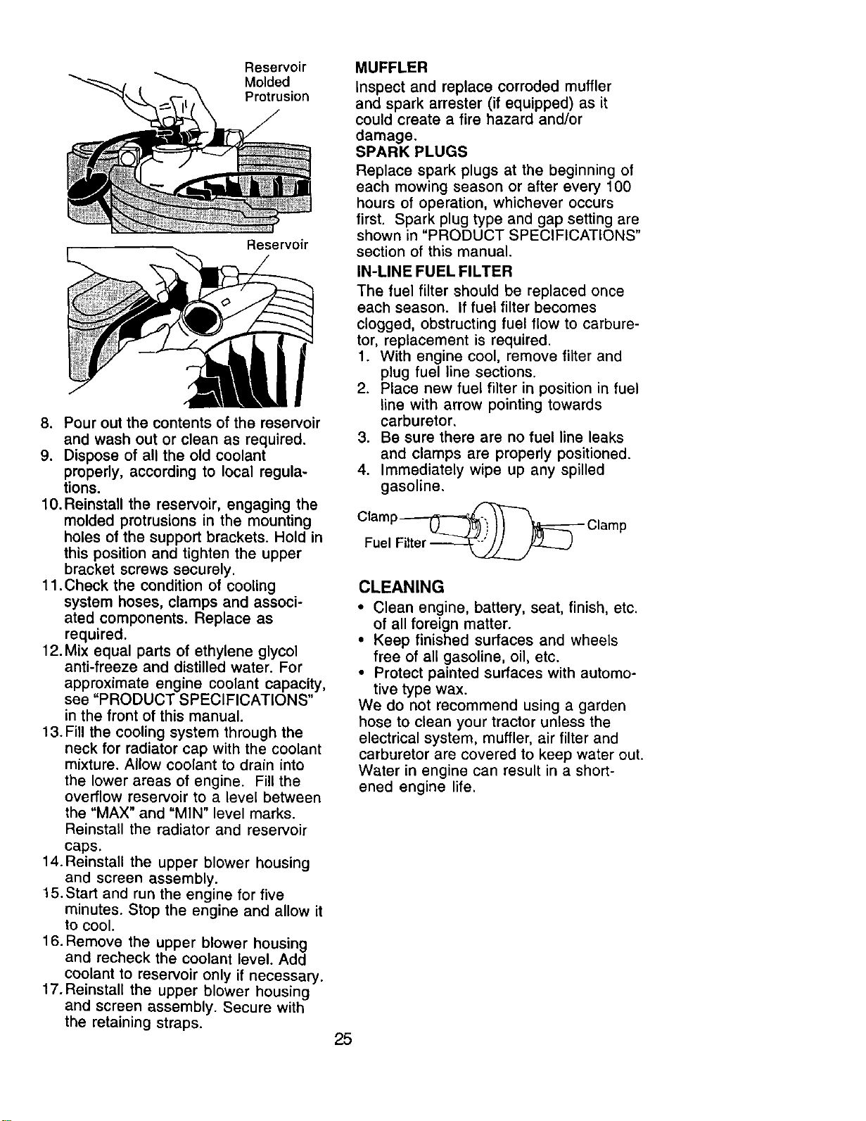
6. The coolant reservoir has three (3)
molded protrusions (1 upper and 2
lower) that fit into corresponding
holes in the support brackets. Loosen
the screws that secure the upper
bracket to the radiator enough to
allow the reservoir to be removed.
7. Remove the reservoir cap. Carefully
tip the bracket away from the reser-
voir and lift the reservoir out.
Loosen Screws
24
Reservoir
Molded
Protrusion
Reservoir
8. Pour out the contents of the reservoir
and wash out or clean as required.
9. Dispose of all the old coolant
properly, according to local regula-
tions.
10.Reinstall the reservoir, engaging the
molded protrusions in the mounting
holes of the support brackets. Hold in
this position and tighten the upper
bracket screws securely.
11 .Check the condition of cooling
system hoses, clamps and associ-
ated components. Replace as
required.
12. Mix equal parts of ethylene glycol
anti-freeze and distilled water. For
approximate engine coolant capacity,
see "PRODUCT SPECIFICATIONS"
in the front of this manual.
13.Fill the cooling system through the
neck for radiator cap with the coolant
mixture. Allow coolant to drain into
the lower areas of engine. Fill the
overflow reservoir to a level between
the "MAX" and "MIN" level marks.
Reinstall the radiator and reservoir
caps.
14.Reinstall the upper blower housing
and screen assembly.
15.Start and run the engine for five
minutes. Stop the engine and allow it
to cool.
16. Remove the upper blower housing
and recheck the coolant level. Add
coolant to reservoir only if necessary.
17.Reinstall the upper blower housing
and screen assembly. Secure with
the retaining straps.
MUFFLER
Inspect and replace corroded muffler
and spark arrester (if equipped) as it
could create a fire hazard and/or
damage.
SPARK PLUGS
Replace spark plugs at the beginning of
each mowing season or after every 100
hours of operation, whichever occurs
first. Spark plug type and gap setting are
shown in "PRODUCT SPECIFICATIONS"
section of this manual.
IN-LINE FUEL FILTER
The fuel filter should be replaced once
each season. If fuel filter becomes
clogged, obstructing fuel flow to carbure-
tor, replacement is required.
1. With engine cool, remove filter and
plug fuel line sections.
2. Place new fuel filter in position in fuel
line with arrow pointing towards
carburetor.
3. Be sure there are no fuel line leaks
and clamps are properly positioned.
4. Immediately wipe up any spilled
gasoline.
Clamp _ Clamp
Fuel Filter
CLEANING
• Clean engine, battery, seat, finish, etc.
of all foreign matter.
• Keep finished surfaces and wheels
free of all gasoline, oil, etc.
• Protect painted surfaces with automo-
tive type wax.
We do not recommend using a garden
hose to clean your tractor unless the
electrical system, muffler, air filter and
carburetor are covered to keep water out.
Water in engine can result in a short-
ened engine life.
25
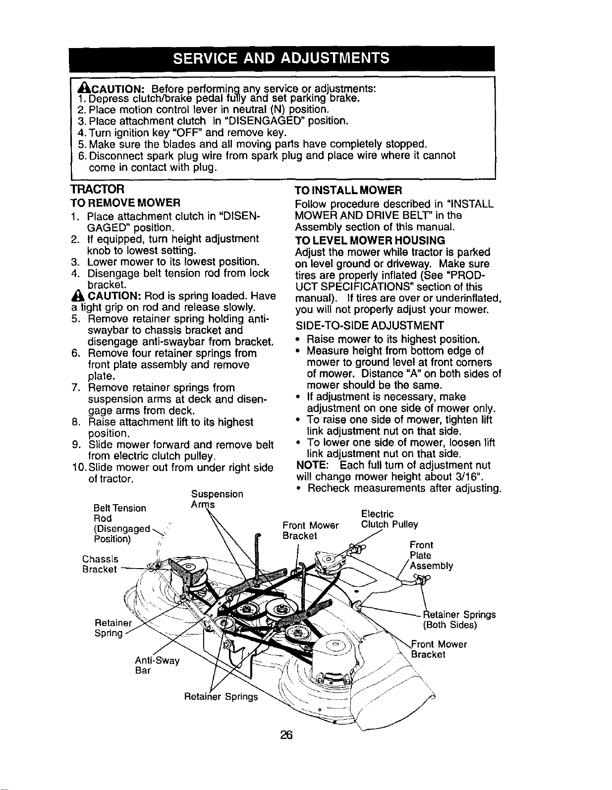
_:_CAUTION: Before performin_ any service or adjustments:
1. Depress clutch/brake peaal fu,y ana set parking DraKe.
2. Place motion control lever in neutral (N) position.
3. Place attachment clutch in "DISENGAGED" position.
4. Turn ignition key =OFF" and remove key.
5. Make sure the blades and all moving parts have completely stopped.
6. Disconnect spark plug wire from spark plug and place wire where it cannot
come in contact with plug.
TRACTOR
TO REMOVE MOWER
1. Place attachment clutch in "DISEN-
GAGED" position.
2. If equipped, turn height adjustment
knob to lowest setting.
3. Lower mower to its lowest position.
4. Disengage belt tension rod from lock
bracket.
CAUTION: Rod is spring loaded. Have
a tight grip on rod and release slowly.
5. Remove retainer spring holding anti-
swaybar to chassis bracket and
disengage anti-swaybar from bracket.
6. Remove four retainer springs from
front plate assembly and remove
plate.
7. Remove retainer springs from
suspension arms at deck and disen-
gage arms from deck.
8. Raise attachment lift to its highest
position.
9. Slide mower forward and remove belt
from electric clutch pulley.
10,Slide mower out from under right side
of tractor.
Suspension
Belt Tension
Rod
/
(Disengaged _,'
Position) /
I'
Chassis
Bracket
TO INSTALL MOWER
Follow procedure described in "INSTALL
MOWER AND DRIVE BELT" in the
Assembly section of this manual.
TO LEVEL MOWER HOUSING
Adjust the mower while tractor is parked
on level ground or driveway. Make sure
tires are properly inflated (See =PROD-
UCT SPECIFICATIONS" section of this
manual). If tires are over or underinflated,
you will not properly adjust your mower.
SIDE-TO-SIDE ADJUSTMENT
• Raise mower to its highest position.
• Measure height from bottom edge of
mower to ground level at front corners
of mower. Distance =A" on both sides of
mower should be the same.
• If adjustment is necessary, make
adjustment on one side of mower only.
• To raise one side of mower, tighten lift
link adjustment nut on that side.
• To lower one side of mower, loosen lift
link adjustment nut on that side.
NOTE: Each full turn of adjustment nut
will change mower height about 3/16".
• Recheck measurements after adjusting.
Front Mower
Bracket
Electric
Clutch Pulley
Front
Plate
Retainer
Spring
Anti-Sway
Bar
r Springs
Springs
(Both Sides)
Mower
Bracket
\,
26
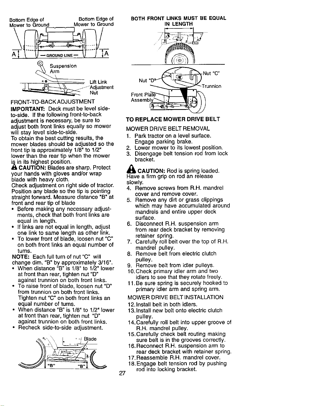
Bottom Edge of Bottom Edge of
Mower to Ground Mower to Ground
\ /
Suspension
Lift Link
__.djustment
' _ Nut
FRONT-TO-BACK ADJUSTMENT
IMPORTANT: Deck must be level side-
to-side. If the following front-to-back
adjustment is necessary, be sure to
adjust both front links equally so mower
will stay level side-to-side.
To obtain the best cutting results, the
mower blades should be adjusted so the
front tip is approximately 1/8" to 1/2"
lower than the rear tip when the mower
is in its highest position.
A CAUTION: Blades are sharp. Protect
your hands with gloves and/or wrap
blade with heavy cloth.
Check adjustment on right side of tractor.
Position any blade so the tip is pointing
straight forward. Measure distance "B" at
front and rear tip of blade
• Before making any necessary adjust-
ments, check that both front links are
equal in length.
• If/inks are not equal in length, adjust
one link to same length as other link.
• To lower front of blade, loosen nut "C"
on both front links an equal number of
turns.
NOTE: Each full turn of nut "C" will
change dim. "B" by approximately 3/16".
• When distance "B" is 1/8" to 1/2" lower
at front than rear, tighten nut "D"
against trunnion on both front links.
• To raise front of blade, loosen nut "D"
from trunnion on both front links.
Tighten nut "C" on both front links an
equal number of turns.
• When distance "B" is 1/8" to 1/2" lower
at front than rear, tighten nut "D"
against trunnion on both front links.
• Recheck side-to-side adjustment.
"B .... B
BOTH FRONT LINKS MUST BE EQUAL
IN LENGTH
Nut Nut "C"
_ _unnion
Front Plate_""'_
Assemb_
TO REPLACE MOWER DRIVE BELT
27
MOWER DRIVE BELT REMOVAL
1. Park tractor on a level surface.
Engage parking brake.
2. Lower mower to its lowest position.
3. Disengage belt tension rod from lock
bracket.
_ CAUTION: Rod is spring loaded.
Have a firm grip on rod an release
slowly.
4. Remove screws from R.H. mandrel
cover and remove cover.
5. Remove any dirt or grass clippings
which may have accumulated around
mandrels and entire upper deck
surface.
6. Disconnect R.H. suspension arm
from rear deck bracket by removing
retainer spring.
7. Carefully roll belt over the top of R.H.
mandrel pulley.
8. Remove belt from electric clutch
pulley.
9. Remove belt from idler pulleys.
10.Check primary idler arm and two
idlers to see that they rotate freely.
11 .Be sure spring is securely hooked to
primary idler arm and spring arm.
MOWER DRIVE BELT INSTALLATION
12.Install belt in both idlers.
13.Install new belt onto electric clutch
pulley.
14.Carefully roll belt into upper groove of
R.H. mandrel pulley.
15.Carefully check belt routing making
sure belt is in the grooves correctly.
16.Reconnect R.H. suspension arm to
rear deck bracket with retainer spring.
17.Reassemble R.H. mandrel cover.
18.Engage belt tension rod by pushing
rod into locking bracket.
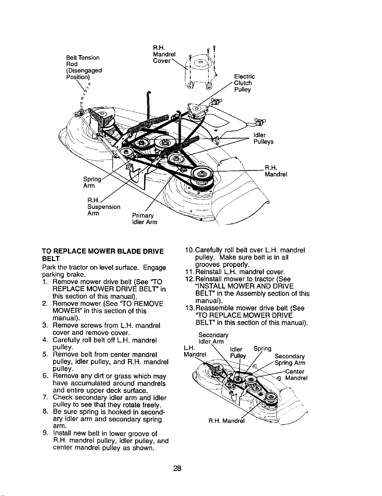
BeltTension
Rod
(Disengaged
Position)
a,H.
Mandrel
Cover_
Electric
Clutch
Pulley
Idler
Pulleys
Arm
R.H.
Suspension
Arm
Primary
Idler Arm
R.H.
Mandrel
TO REPLACE MOWER BLADE DRIVE
BELT
Park the tractor on level surface. Engage
parking brake.
1. Remove mower drive belt (See "TO
REPLACE MOWER DRIVE BELT" in
this section of this manual).
2. Remove mower (See "TO REMOVE
MOWER" in this section of this
manual).
3. Remove screws from L.H. mandrel
cover and remove cover.
4. Carefully roll belt off L.H. mandrel
pulley.
5. Remove belt from center mandrel
pulley, idler pulley, and R.H. mandrel
pulley.
6. Remove any dirt or grass which may
have accumulated around mandrels
and entire upper deck surface.
7. Check secondary idler arm and idler
pulley to see that they rotate freely.
8. Be sure spring is hooked in second-
ary idler arm and secondary spring
arm.
9. Install new belt in lower groove of
R.H. mandrel pulley, idler pulley, and
center mandrel pulley as shown.
10.Carefully roll belt over L.H. mandrel
pulley. Make sure belt is in all
grooves properly.
11 .Reinstall L.H. mandrel cover.
12. Reinstall mower to tractor (See
"INSTALL MOWER AND DRIVE
BELT" in the Assembly section of this
manual).
13. Reassemble mower drive belt (See
"TO REPLACE MOWER DRIVE
BELT" in this section of this manual).
Secondary
Idler Arm
L.H. Idler
Mandrel
Secondary
Arm
Mandrel
R.H.M
28
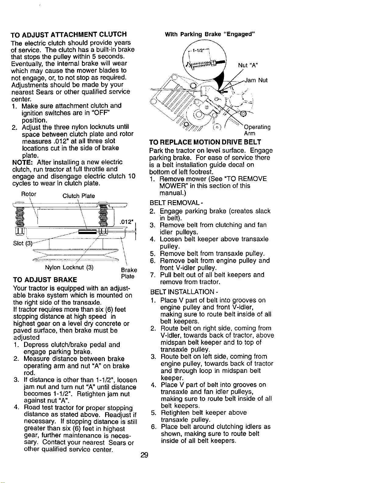
TO ADJUST A'n'ACHMENT CLUTCH
The electric clutch should provide years
of service. The clutch has a built-in brake
that stops the pulley within 5 seconds.
Eventually, the internal brake will wear
which may cause the mower blades to
not engage, or, to not stop as required.
Adjustments should be made by your
nearest Sears or other qualified service
center.
1. Make sure attachment clutch and
ignition switches are in "OFF'
position.
2. Adjust the three nylon Iocknuts until
space between clutch plate and rotor
measures .012" at all three slot
locations cut in the side of brake
plate.
NOTE: After installing a new electric
clutch, run tractor at full throttle and
engage and disengage electric clutch 10
cycles to wear in clutch plate.
Rotor Clutch Plate
Slot
Nylon Locknut (3)
TO ADJUST BRAKE
Brake
Plate
Your tractor is equipped with an adjust-
able brake system which is mounted on
the right side of the transaxle.
If tractor requires more than six (6) feet
stopping distance at high speed in
highest gear on a level dry concrete or
paved surface, then brake must be
adjusted
1. Depress clutch/brake pedal and
engage parking brake.
2. Measure distance between brake
operating arm and nut "A" on brake
rod.
3. If distance is other than 1-1/2", loosen
jam nut and turn nut "A" until distance
becomes 1-1/2". Retighten jam nut
against nut "A".
4. Road test tractor for proper stopping
distance as stated above. Readjust if
necessary. If stopping distance is still
greater than six (6) feet in highest
gear, further maintenance is neces-
sary. Contact your nearest Sears or
other qualified service center.
With Parking Brake "Engaged"
Nut
:)perating
Arm
TO REPLACE MOTION DRIVE BELT
Park the tractor on level surface. Engage
parking brake. For ease of service there
is a belt installation guide decal on
bottom of left footrest.
1. Remove mower (See "TO REMOVE
MOWER" in this section of this
manual.)
BELT REMOVAL -
2. Engage parking brake (creates slack
in belt).
3. Remove belt from clutching and fan
idler pulleys.
4. Loosen belt keeper above transaxle
pulley.
5. Remove belt from transaxle pulley.
6. Remove belt from engine pulley and
front V-idler pulley.
7. Pull belt out of all belt keepers and
remove from tractor.
BELT INSTALLATION -
1. Place V part of belt into grooves on
engine pulley and front V-idler,
making sure to route belt inside of all
belt keepers.
2. Route belt on right side, coming from
V-idler, towards back of tractor, above
midspan belt keeper and to top of
transaxle pulley.
3. Route belt on left side, coming from
engine pulley, towards back of tractor
and through loop in midspan belt
keeper.
4. Place V part of belt into grooves on
transaxle and fan idler pulleys,
making sure to route belt inside of all
belt keepers.
5. Retighten belt keeper above
transaxle pulley.
6. Place belt around clutching idlers as
shown, making sure to route belt
inside of all belt keepers.
29
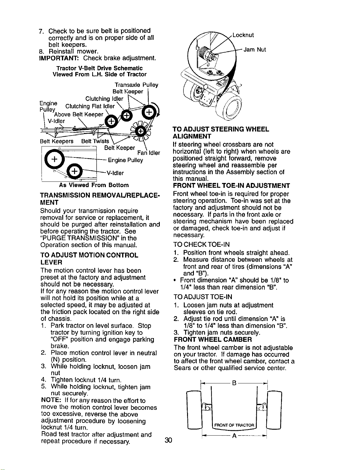
7. Check to be sure belt is positioned
correctly and is on proper side of all
belt keepers.
8. Reinstall mower.
IMPORTANT." Check brake adjustment.
Tractor V-Belt Drive Schematic
Viewed From L.H. Side of Tractor
Transaxle Pulley
Clutching Id
Engine Clutching
Pu"_YAbove Belt Keeper
V-Idler
Belt Keepers Belt Twists
I _° 1 Belt Keeper
_ Engine Pulley
_V-Idler
As Viewed From Bottom
Idler
TRANSMISSION REMOVAL/REPLACE-
MENT
Should your transmission require
removal for service or replacement, it
should be purged after reinstallation and
before operating the tractor. See
"PURGE TRANSMISSION" in the
Operation section of this manual.
TO ADJUST MOTION CONTROL
LEVER
The motion control lever has been
preset at the factory and adjustment
should not be necessary.
If for any reason the motion control lever
will not hold its position while at a
selected speed, it may be adjusted at
the friction pack located on the right side
of chassis.
1. Park tractor on level surface. Stop
tractor by turning ignition key to
"OFF" position and engage parking
brake.
2. Place motion control lever in neutral
(N) position.
3. While holding Iocknut, loosen jam
nut
4. Tighten !ocknut 1/4 turn.
5. While holding Iocknut, tighten jam
nut securely.
NOTE: If for any reason the effort to
move the motion control lever becomes
too excessive, reverse the above
adjustment procedure by loosening
Iocknut 1/4 turn.
Road test tractor after adjustment and
repeat procedure if necessary.
Nut
TO ADJUST STEERING WHEEL
ALIGNMENT
If steering wheel crossbars are not
horizontal (left to right) when wheels are
positioned straight forward, remove
steering wheel and reassemble per
instructions in the Assembly section of
this manual.
FRONT WHEEL TOE-IN ADJUSTMENT
Front wheel toe-in is required for proper
steering operation. Toe-in was set at the
factory and adjustment should not be
necessary. If parts in the front axle or
steering mechanism have been replaced
or damaged, check toe-in and adjust if
necessary.
TO CHECK TOE-IN
1. Position front wheels straight ahead.
2. Measure distance between wheels at
front and rear of tires (dimensions "A"
and "B').
• Front dimension "A" should be 1/8" to
1/4" less than rear dimension "B".
TO ADJUST TOE-IN
1. Loosen jam nuts at adjustment
sleeves on tie rod.
2. Adjust tie rod until dimension "A" is
1/8" to 1/4" less than dimension "B".
3. Tighten jam nuts securely.
FRONT WHEEL CAMBER
The front wheel camber is not adjustable
on your tractor. If damage has occurred
to affect the front wheel camber, contact a
Sears or other qualified service center.
3O
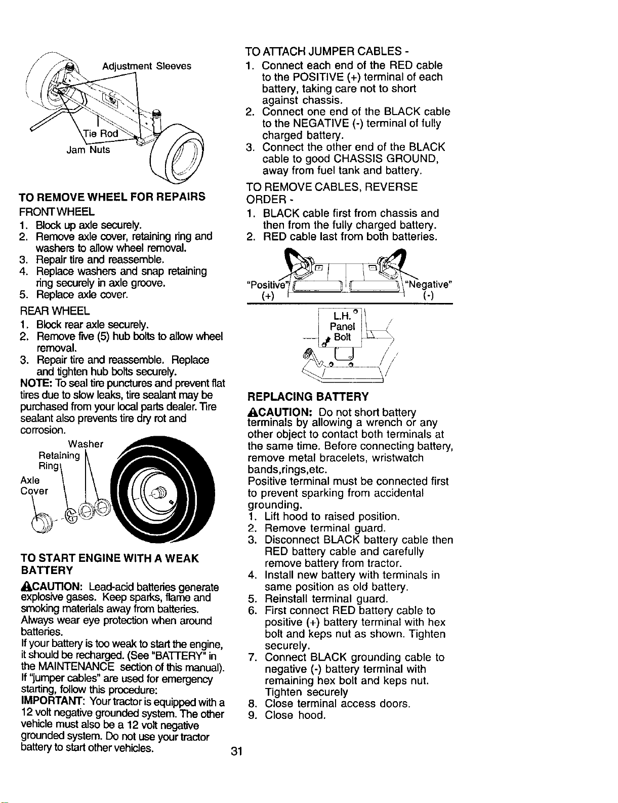
Adjustment Sleeves
Jam Nuts
TO REMOVE WHEEL FOR REPAIRS
FRONTWHEEL
1. Block up axle securely.
2. Remove axle cover, retaining ring and
washers to allow wheel removal.
3. Repair tire and reassemble.
4. Replace washers and snap retaining
ring securely in axle groove.
5. Replace axle cover.
REAR WHEEL
1. Block rear axle securely.
2. Remove five (5) hub bolts to allow wheel
removal.
3. Repair tire and reassemble. Replace
and tighten hub bolts securely.
NOTE: To seal tire punctures and prevent fiat
tires due to slow leaks, tire seatant may be
purchased from your local parts dealer. "13re
sealant also prevents tire dry rot and
corrosion.
Washer
Retaining
Rinc
Axle
Cover
TO START ENGINE WITH A WEAK
BATTERY
_t,CAUTION: Lead-acid batteries generate
explosive gases. Keep sparks, flame and
smoking materials away from batteries.
Always wear eye protection when around
batteries.
If your battery is too weak to start the engine,
it should be recharged. (See "BA]-FERY" in
the MAINTENANCE section of this manual).
If "jumper cables" are used for emergency
starting, follow this procedure:
IMPORTANT: Your tractor is equipped with a
12 volt negative grounded system. The other
vehicle must also be a 12 volt negative
grounded system. Do not use your tractor
battery to start other vehicles.
31
TO ATFACH JUMPER CABLES -
1. Connect each end of the RED cable
to the POSITIVE (+) terminal of each
battery, taking care not to short
against chassis.
2. Connect one end of the BLACK cable
to the NEGATIVE (-) terminal of fully
charged battery.
3. Connect the other end of the BLACK
cable to good CHASSIS GROUND,
away from fuel tank and battery.
TO REMOVE CABLES, REVERSE
ORDER -
1. BLACK cable first from chassis and
then from the fully charged battery.
2. RED cable last from both batteries.
(+)/_, _'_'e_a_ive"
,t
/'
REPLACING BATTERY
_kCAUTION: Do not short battery
terminals by allowing a wrench or any
other object to contact both terminals at
the same time. Before connecting battery,
remove metal bracelets, wristwatch
bands,rings,etc.
Positive terminal must be connected first
to prevent sparking from accidental
grounding.
1. Lift hood to raised position.
2. Remove terminal guard.
3. Disconnect BLACK battery cable then
RED battery cable and carefully
remove battery from tractor.
4. Install new battery with terminals in
same position as old battery.
5. Reinstall terminal guard.
6. First connect RED battery cable to
positive (+) battery terminal with hex
bolt and keps nut as shown. Tighten
securely.
7. Connect BLACK grounding cable to
negative (-) battery terminal with
remaining hex bolt and keps nut.
Tighten securely
Close terminal access doors..
9. Close hood.
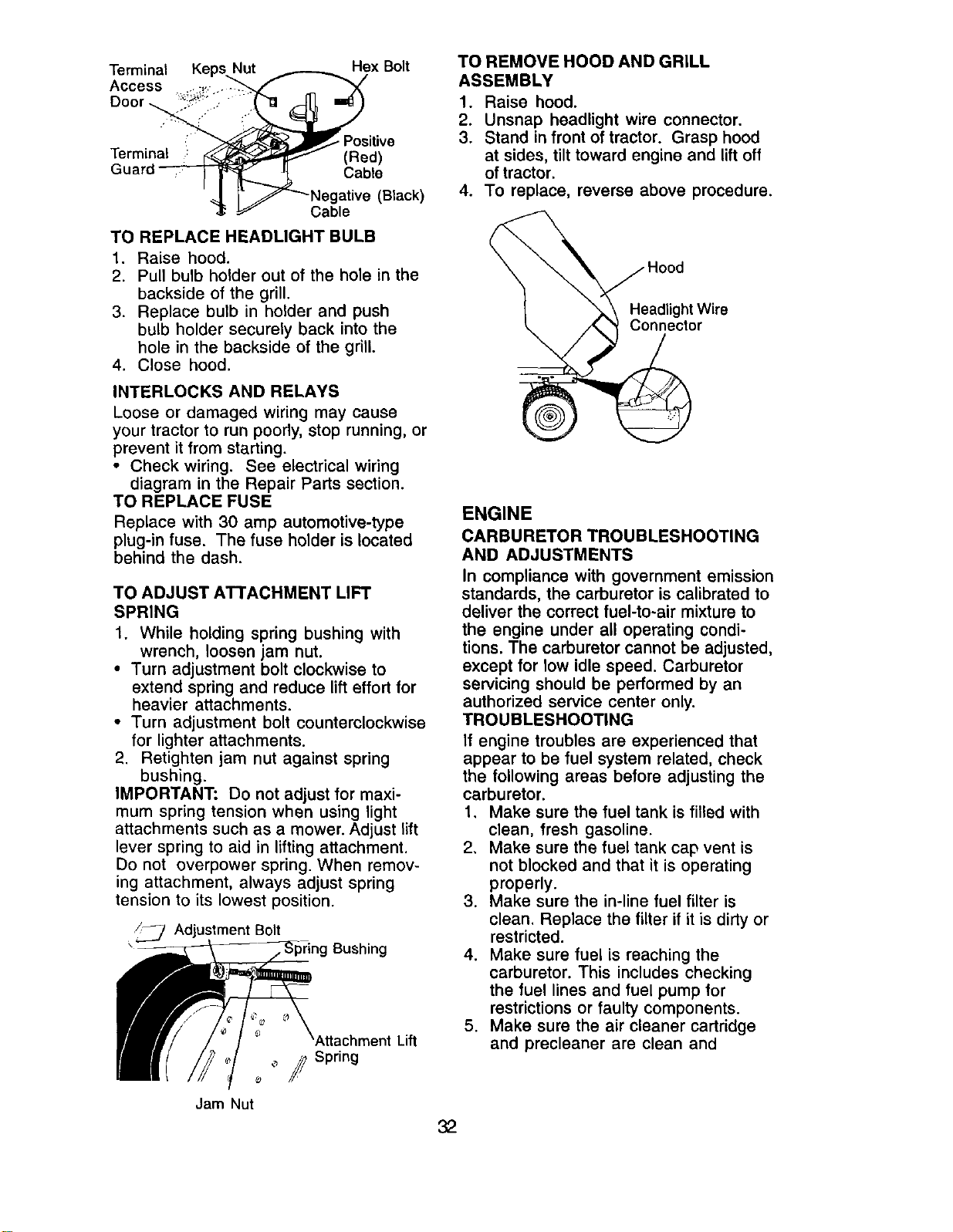
Terminal KepsNut /,....__._ Hex Bolt
Access .:i_.-.. -"'-_ _ _._
Ooor_ _
__'_'_ Positive
Terminal ; _ (Red)
Guard _ Cable
-_ l- JJ_-"-Negarlve (Black)
,!_ _ Cable
TO REPLACE HEADLIGHT BULB
1. Raise hood.
2. Pull bulb holder out of the hole in the
backside of the grill.
3. Replace bulb in holder and push
bulb holder securely back into the
hole in the backside of the grill.
4. Close hood.
INTERLOCKS AND RELAYS
Loose or damaged wiring may cause
your tractor to run poorly, stop running, or
prevent it from starting.
• Check wiring. See electrical wiring
diagram in the Repair Parts section.
TO REPLACE FUSE
Replace with 30 amp automotive-type
plug-in fuse. The fuse holder is located
behind the dash.
TO ADJUST ATTACHMENT LIFT
SPRING
1. While holding spring bushing with
wrench, loosen jam nut.
• Turn adjustment bolt clockwise to
extend spring and reduce lift effort for
heavier attachments.
• Turn adjustment bolt counterclockwise
for lighter attachments.
2. Retighten jam nut against spring
bushing.
IMPORTANT: Do not adjust for maxi-
mum spring tension when using light
attachments such as a mower. Adjust lift
lever spring to aid in lifting attachment.
Do not overpower spring. When remov-
ing attachment, always adjust spring
tension to its lowest position.
/_ Adjustment Bolt
Bushing
Jam Nut
Lift
TO REMOVE HOOD AND GRILL
ASSEMBLY
1. Raise hood.
2. Unsnap headlight wire connector.
3. Stand in front of tractor. Grasp hood
at sides, tilt toward engine and lift off
of tractor.
4. To replace, reverse above procedure.
Headlight Wire
Connector
ENGINE
CARBURETOR TROUBLESHOOTING
AND ADJUSTMENTS
In compliance with government emission
standards, the carburetor is calibrated to
deliver the correct fuel-to-air mixture to
the engine under all operating condi-
tions. The carburetor cannot be adjusted,
except for low idle speed. Carburetor
servicing should be performed by an
authorized service center only.
TROUBLESHOOTING
If engine troubles are experienced that
appear to be fuel system related, check
the following areas before adjusting the
carburetor.
1. Make sure the fuel tank is filled with
clean, fresh gasoline.
2. Make sure the fuel tank cap vent is
not blocked and that it is operating
properly.
3. Make sure the in-line fuel filter is
clean. Replace the filter if it is dirty or
restricted.
4. Make sure fuel is reaching the
carburetor. This includes checking
the fuel lines and fuel pump for
restrictions or faulty components.
5. Make sure the air cleaner cartridge
and precleaner are clean and
32
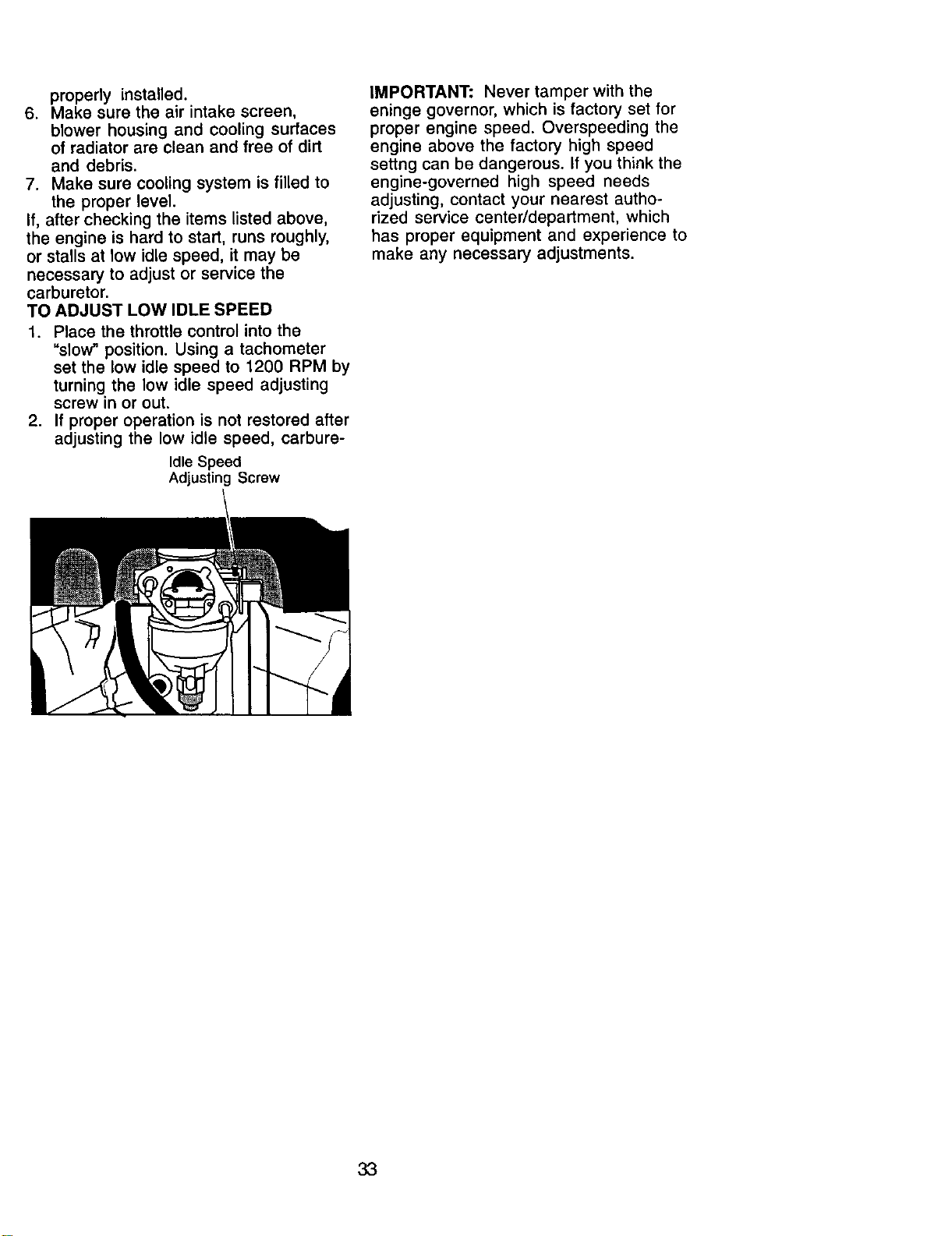
properly installed.
6. Make sure the air intake screen,
blower housing and cooling surfaces
of radiator are clean and free of dirt
and debris.
7. Make sure cooling system is filled to
the proper level.
If, after checking the items listed above,
the engine is hard to start, runs roughly,
or stalls at low idle speed, it may be
necessary to adjust or service the
carburetor.
TO ADJUST LOW IDLE SPEED
1. Place the throttle control into the
"slow" position. Using a tachometer
set the low idle speed to 1200 RPM by
turning the low idle speed adjusting
screw in or out.
2. If proper operation is not restored after
adjusting the low idle speed, carbure-
Idle Speed
Adjusting Screw
IMPORTANT: Never tamper with the
eninge governor, which is factory set for
proper engine speed. Overspeeding the
engine above the factory high speed
settng can be dangerous. If you think the
engine-governed high speed needs
adjusting, contact your nearest autho-
rized service center/department, which
has proper equipment and experience to
make any necessary adjustments.
33
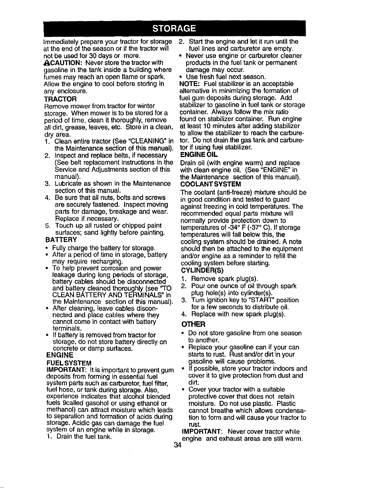
Immediately prepare your tractor for storage
at the end of the season or if the tractor will
not be used for 30 days or more.
_LCAUTION: Never store the tractor with
gasoline in the tank inside a building where
fumes may reach an open flame or spark.
Allow the engine to cool before storing in
any enclosure.
TRACTOR
Remove mower from tractor for winter
storage. When mower is to be stored for a
period of time, clean it thoroughly, remove
all dirt, grease, leaves, etc. Store in a clean,
dry area.
1. Clean entire tractor (See "CLEANING" in
the Maintenance section of this manual).
2. Inspect and replace belts, if necessary
(See belt replacement instructions in the
Service and Adjustments section of this
manual).
3. Lubricate as shown in the Maintenance
section of this manual.
4. Be sure that all nuts, bolts and screws
are securely fastened. Inspect moving
parts for damage, breakage and wear.
Replace if necessary.
5. Touch up all rusted or chipped paint
surfaces; sand lightly before painting.
BATTERY
• Fully charge the battery for storage.
• After a period of time in storage, battery
may require recharging.
• To help prevent corrosion and power
leakage during long periods of storage,
battery cables should be disconnected
and battery cleaned thoroughly (see "TO
CLEAN BAI-rERY AND TERMINALS" in
the Maintenance section of this manual).
• After cleaning, leave cables discon-
nected and place cables where they
cannot come in contact with battery
terminals.
• If battery is removed from tractor for
storage, do not store battery directly on
concrete or damp surfaces.
ENGINE
FUEL SYSTEM
IMPORTANT: It is important to prevent gum
deposits from forming in essential fuel
system parts such as carburetor, fuel filter,
fuel hose, or tank during storage. Also,
experience indicates that alcohol blended
fuels 9called gasohol or using ethanol or
methanol) can attract moisture which leads
to separation and formation of acids during
storage. Acidic gas can damage the fuel
system of an engine while in storage.
1. Drain the fuel tank.
2. Start the engine and let it run until the
fuel lines and carburetor are empty.
• Never use engine or carburetor cleaner
products in the fuel tank or permanent
damage may occur.
• Use fresh fuel next season.
NOTE: Fuel stabilizer is an acceptable
altemative in minimizing the formation of
fuel gum deposits during storage. Add
stabilizer to gasoline in fuel tank or storage
container. Always follow the mix ratio
found on stabilizer container. Run engine
at least 10 minutes after adding stabilizer
to allow the stabilizer to reach the carbure-
tor. Do not drain the gas tank and carbure-
tor if using fuel stabilizer.
ENGINE OIL
Drain oil (with engine warm) and replace
with clean engine oil. (See "ENGINE" in
the Maintenance section of this manual).
COOLANT SYSTEM
The coolant (anti-freeze) mixture should be
in good condition and tested to guard
against freezing in cold temperatures. The
recommended equal parts mixture will
normally provide protection clown to
temperatures of -34 ° F (-37 ° C). If storage
temperatures will fall below this, the
cooling system should be drained. A note
should then be attached to the equipment
and/or engine as a reminder to refill the
cooling system before starting.
CYLINDER(S)
1. Remove spark plug(s).
2. Pour one ounce of oil through spark
plug hole(s) into cylinder(s).
3. Turn ignition key to "START" position
for a few seconds to distribute oil.
4. Replace with new spark plug(s).
OTHER
• Do not store gasoline from one season
to another.
• Replace your gasoline can if your can
starts to rust. Rust and/or dirt in your
gasoline will cause problems.
• If possible, store your tractor indoors and
cover it to give protection from dust and
dirt.
• Cover your tractor with a suitable
protective cover that does not retain
moisture. Do not use plastic. Plastic
cannot breathe which allows condensa-
tion to form and will cause your tractor to
rust.
IMPORTANT: Never cover tractor while
engine and exhaust areas are still warm.
34
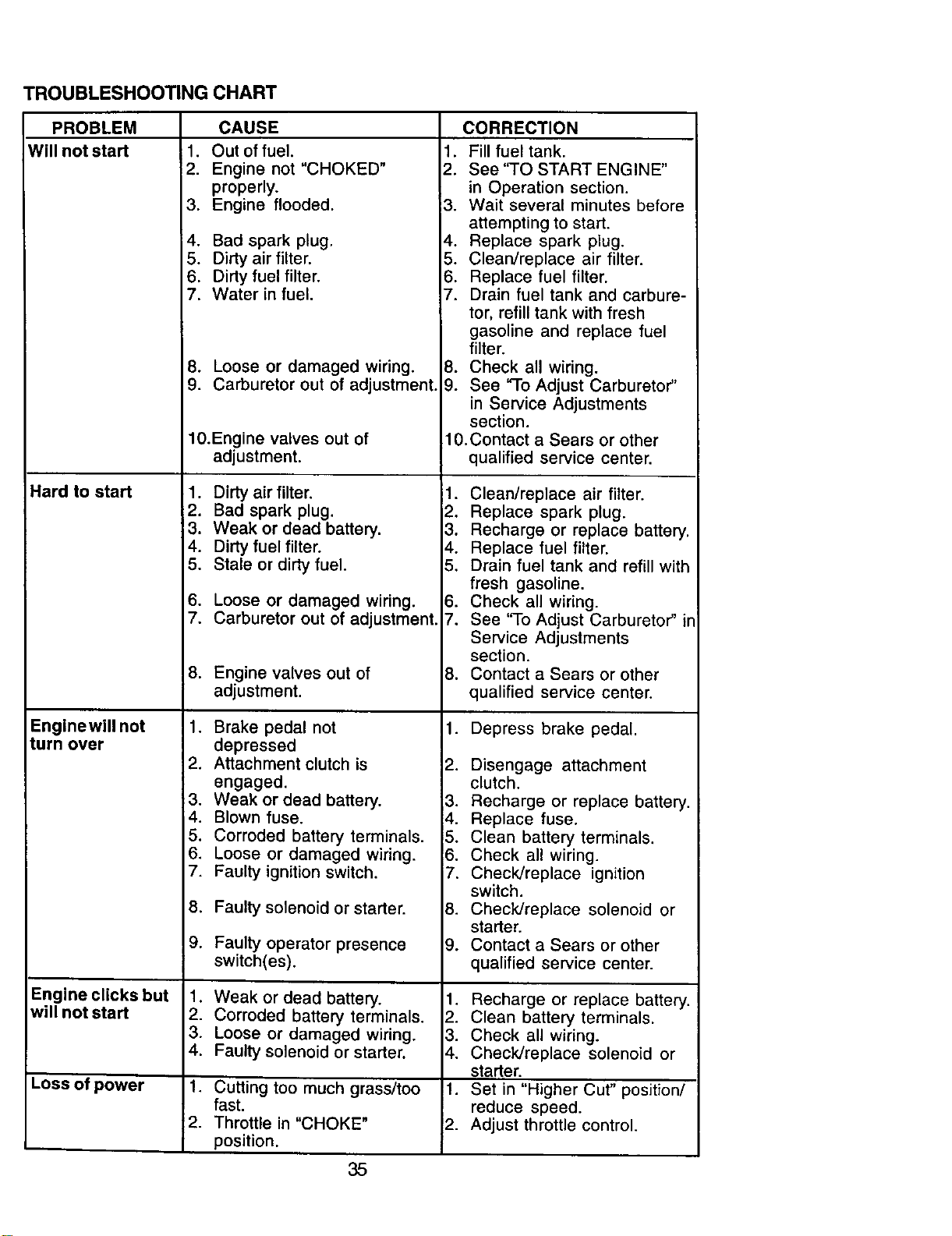
TROUBLESHOOTING CHART
PROBLEM
Will not start
Hard to start
Enginewill not
turn over
Engine clicks but
will not start
CAUSE
• Out of fuel.
2. Engine not "CHOKED"
properly.
3. Engine flooded. 3.
4. Bad spark plug. 4.
5. Dirty air filter. 5.
6. Dirty fuel filter• 6.
7. Water in fuel. 7.
8, Loose or damaged wiring. 8.
9. Carburetor out of adjustment. 9.
10.Engine valves out of
adjustment.
1. Dirty air filter.
2. Bad spark plug.
3. Weak or dead battery.
4. Dirty fuel filter,
5. Stale or dirty fuel.
6. Loose or damaged wiring•
7. Carburetor out of adjustment.
8. Engine valves out of
adjustment.
CORRECTION
1. Fill fuel tank.
2. See "TO START ENGINE"
in Operation section.
Wait several minutes before
attempting to start.
Replace spark plug.
Cleardreplace air filter.
Replace fuel filter.
Drain fuel tank and carbure-
tor, refill tank with fresh
gasoline and replace fuel
filter•
Check all wiring.
See "To Adjust Carburetor"
in Service Adjustments
section.
10.Contact a Sears or other
qualified service center•
1. Clean/replace air filter.
2, Replace spark plug.
3. Recharge or replace battery.
4. Replace fuel filter.
5, Drain fuel tank and refill with
fresh gasoline•
6. Check all wiring.
7, See 'qo Adjust Carburetor" in
1. Brake pedal not
depressed
2. Attachment clutch is
engaged.
3. Weak or dead battery.
.
5.
6.
7.
Service Adjustments
section,
8. Contact a Sears or other
qualified service center.
1. Depress brake pedal.
2. Disengage attachment
clutch•
3. Recharge or replace battery.
.
.
.
2.
3.
4.
i
Loss of power 1•
12.
35
Blown fuse• 4.
Corroded battery terminals. 5,
Loose or damaged wiring. 8.
Faulty ignition switch. 7.
Faulty solenoid or starter. 8.
Faulty operator presence 9.
switch(es).
Weak or dead battery. 1.
Corroded battery terminals. 2.
Loose or damaged wiring• 3.
Faulty solenoid or starter. 4.
Cutting too much grass/too 1.
fast.
Throttle in "CHOKE" 2.
position.
Replace fuse•
Clean battery terminals.
Check all wiring.
Check/replace ignition
switch.
Check/replace solenoid or
starter.
Contact a Sears or other
qualified service center•
Recharge or replace battery.
Clean battery terminals.
Check all wiring.
Check/replace solenoid or
starter.
Set in "Higher Cut" position/
reduce speed.
Adjust throttle control.
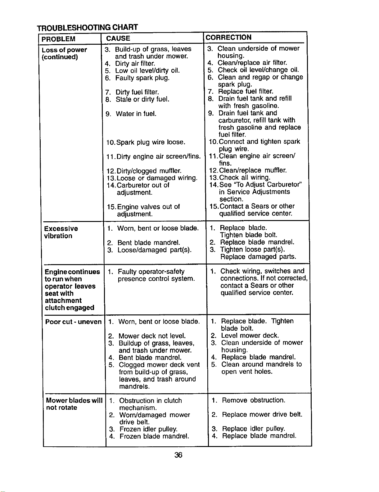
TROUBLESHOOTING CHART
CAUSE
PROBLEM
Loss of power
(continued)
Excessive
vibration
Engine continues
to run when
operator leaves
seat with
attachment
clutch engaged
Poor cut - uneven
Mower blades will
not rotate
3. Build-up of grass, leaves
and trash under mower.
4. Dirty air filter.
5. Low oil level/dirty oil.
6. Faulty spark plug.
7. Dirty fuel filter.
8. Stale or dirty fuel.
9. Water in fuel.
10.Spark plug wire loose.
1 1. Dirty engine air screen/fins.
12. Dirty/clogged muffler.
13.Loose or damaged wiring.
14.Carburetor out of
adjustment.
15. Engine valves out of
adjustment.
1. Worn, bent or loose blade.
2. Bent blade mandrel.
3. Loose/damaged part(s).
1. Faulty operator-safety
presence control system.
.
2.
3.
4.
5.
Worn, bent or loose blade.
Mower deck not level.
Buildup of grass, leaves,
and trash under mower.
Bent blade mandrel.
Clogged mower deck vent
from build-up of grass,
leaves, and trash around
mandrels.
1. Obstruction in clutch
mechanism.
2. Worn/damaged mower
drive belt.
3. Frozen idler pulley.
4. Frozen blade mandrel.
CORRECTION
3. Clean underside of mower
housing.
4. Clean/replace air filter.
5. Check oil leveVchange oil.
6. Clean and regap or change
spark plug.
7. Replace fuel filter.
8. Drain fuel tank and refill
with fresh gasoline.
9. Drain fuel tank and
carburetor, refill tank with
fresh gasoline and replace
fuel filter.
10.Connect and tighten spark
plug wire.
11.Clean engine air screen/
fins.
12.Clean/replace muffler.
13.Check all wiring.
14. See "To Adjust Carburetor"
in Service Adjustments
section.
15. Contact a Sears or other
qualified service center.
1. Replace blade.
Tighten blade bolt.
2. Replace blade mandrel.
3. Tighten loose part(s).
Replace damaged parts.
.
Check wiring, switches and
connections. If not corrected
contact a Sears or other
qualified service center.
1. Replace blade. Tighten
blade bolt.
2. Level mower deck.
3. Clean underside of mower
housing.
4. Replace blade mandrel.
5. Clean around mandrels to
open vent holes.
1. Remove obstruction.
2. Replace mower drive belt.
3. Replace idler pulley.
4. Replace blade mandrel.
36
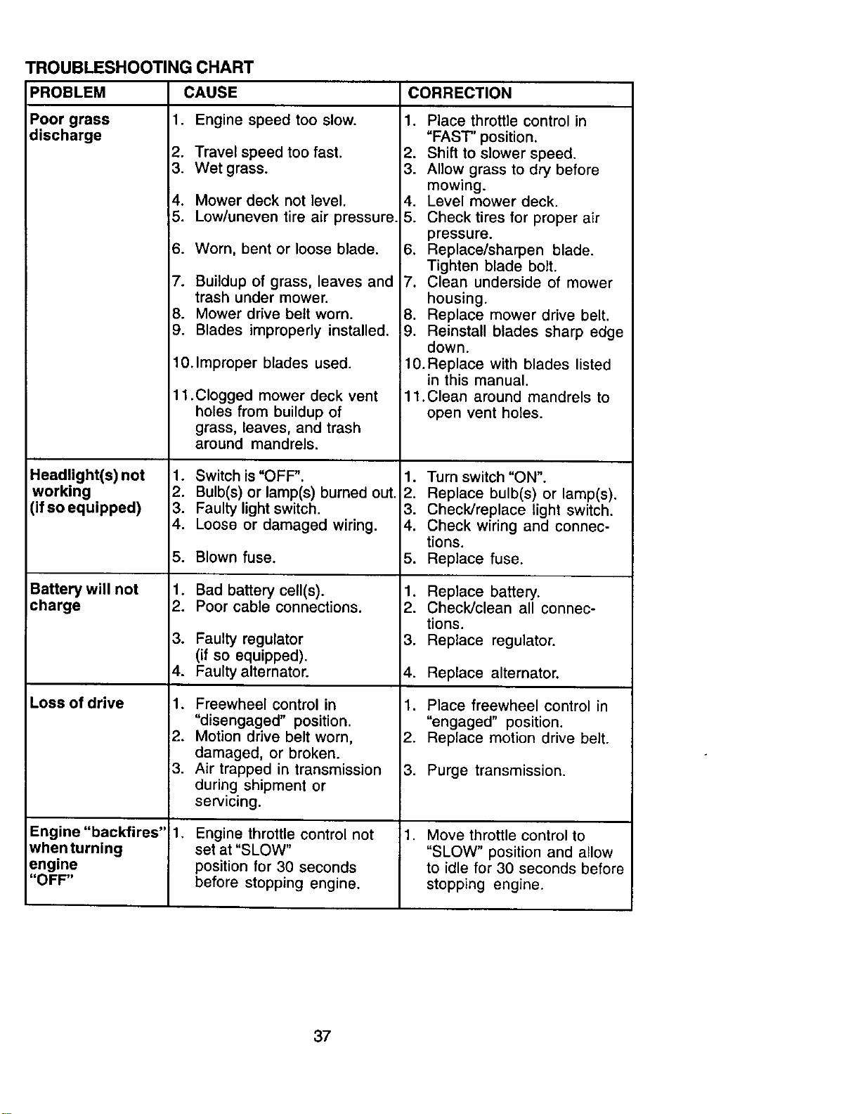
TROUBLESHOOTING CHART
PROBLEM
Poor grass
discharge
2.
3.
4.
5.
6.
7.
8.
9.
Headlight(s) not
working
(if so equipped)
Battery willnot
charge
Loss of drive
Engine "backfires"
whenturning
engine
"OFF"
CAUSE CORRECTION
1. Engine speed too slow.
Travelspeed too fast.
Wet grass.
Mower deck not level.
Low/uneven tire air pressure.
Worn, bent or loose blade.
Buildup of grass, leaves and
trash under mower.
Mower drive belt worn.
Blades improperly installed.
10.Improper blades used.
11 .Clogged mower deck vent
holes from buildup of
grass, leaves, and trash
around mandrels.
1. Switch is "OFF".
2. Bulb(s) or lamp(s) burned out.
3. Faulty light switch.
4. Loose or damaged wiring.
5. Blown fuse.
1. Bad battery cell(s).
2. Poor cable connections.
3. Faulty regulator
(if so equipped).
4. Faulty alternator.
1. Freewheel control in
"disengaged" position.
2. Motion drive belt worn,
damaged, or broken.
3. Air trapped in transmission
during shipment or
servicing.
,
Engine throttle control not
set at "SLOW"
position for 30 seconds
before stopping engine.
1. Place throttle control in
"FAST' position.
2. Shift to slower speed.
3. Allow grass to dry before
mowing.
4. Level mower deck.
5. Check tires for proper air
pressure.
6. Replace/sharpen blade.
Tighten blade bolt.
7. Clean underside of mower
housing.
8. Replace mower drive belt.
9. Reinstall blades sharp edge
down.
10.Replace with blades listed
in this manual.
11.Clean around mandrels to
open vent holes.
1. Turn switch "ON".
2. Replace bulb(s) or lamp(s).
3. Check/replace light switch.
4. Check wiring and connec-
tions.
5. Replace fuse.
1. Replace battery.
2. Check/clean all connec-
tions.
3. Replace regulator.
4. Replace alternator.
1. Place freewheel control in
"engaged" position.
2. Replace motion drive belt.
3. Purge transmission.
, Move throttle control to
"SLOW" position and allow
to idle for 30 seconds before
stopping engine.
37
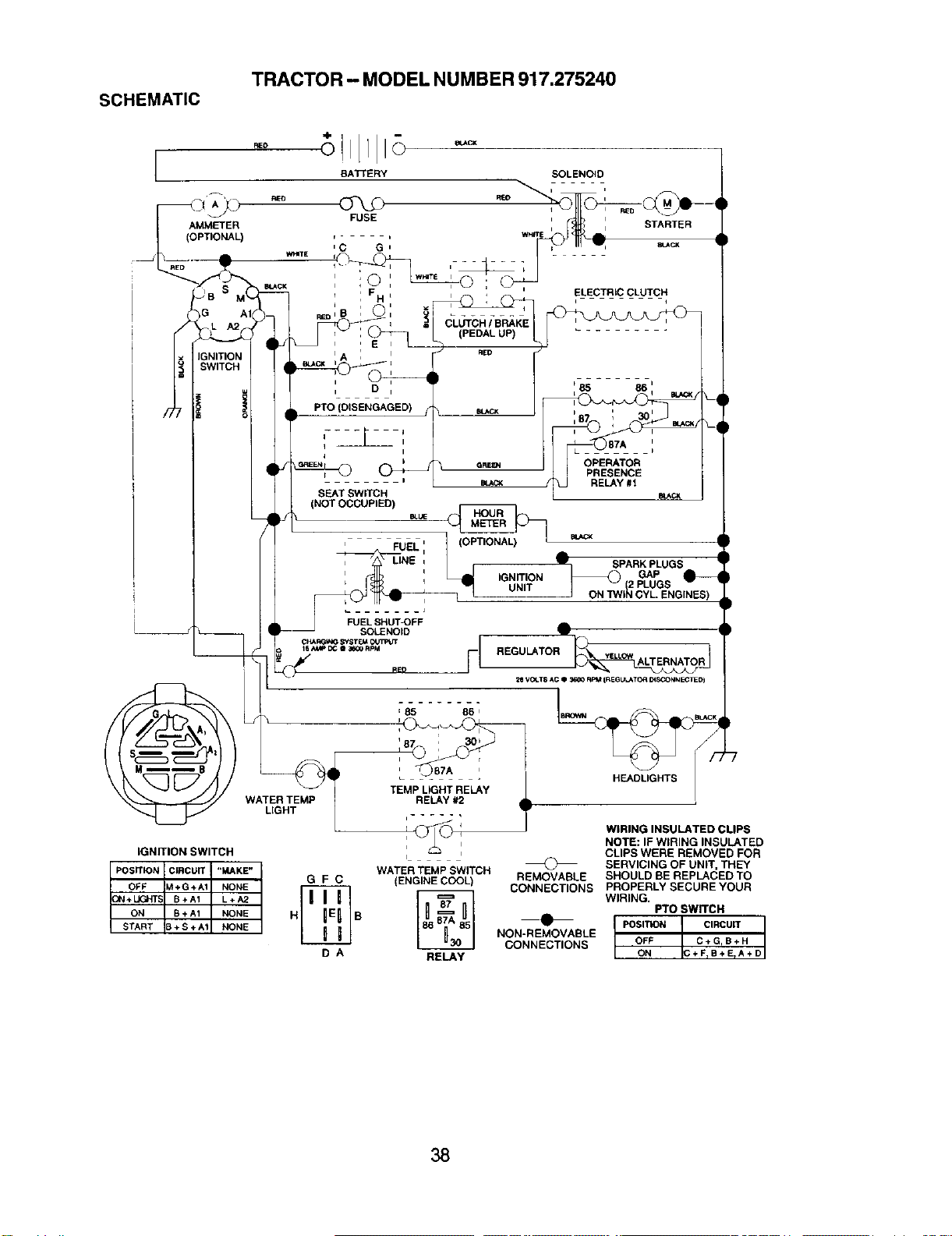
SCHEMATIC
TRACTOR - MODEL NUMBER 917.275240
AMMETER
(OPTIONAL)
IGNITION SWITCH
POSITION CIRCUIT "MAKE"
OFF M+G+A1 NONE
ON + UGHTS B+A1 L÷A2
ON B+A1 NONE
START B ÷ S + A_ NONE
FeED
RED
BATTERY SOLENOID
FUSE , i
, _ , STARTER
r i Wt_JrE dL
' C G ' v b _cx
w.,Ei-
: F H L ELECTRIC CLUTCH
CLUTCH I BRAKE
(PEDAL UP)
: E ,
i RED
WATER TEMP
LIGHT
PTO(
i
SEAT SWITCH
(NOT OCCUPIED)
BLUE
LINE ,
I
r
t
(;n_ OPERATOR
PRESENCE
RELAY #1
BIJ_CK
_1, SPARK PLUGS
GAP
_(2 PLUGS
J ON "iV/IN CYL. ENGINES)
'85 85'
_87 _ 30b
RELAY #2
REGULATOR _ !
28 VOLT8/*C • _ RPM {REGULATOR DISCONNECTI:D)
HEADLIGHTS L
WATER TEMP SWITCH
G F C (ENGINE COOL) REMOVABLE
_ CONNECTIONS
H B
NON-REMOVABLE
CONNECTIONS
D A RELAY
WIRING INSULATED CLIPS
NOTE: IF WIRING INSULATED
CLIPS WERE REMOVED FOR
SERVICING OF UNIT, THEY
SHOULD BE REPLACED TO
PROPERLY SECURE YOUR
WIRING.
PTO SWITCH
POSITION CIRCUIT
OFF C÷GrB+H
ON C+FTB+E_A+D
38
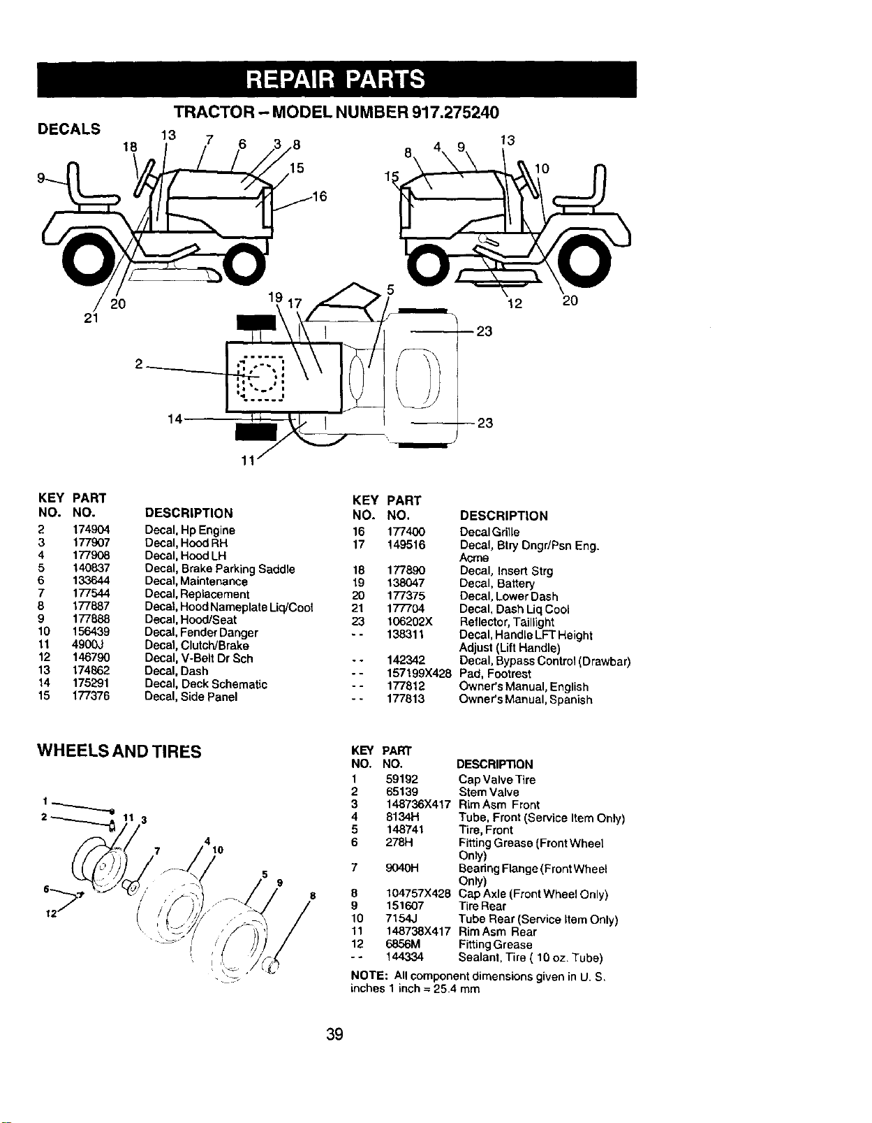
DECALS
9_
TRACTOR - MODEL NUMBER 917.275240
13
18
7 6 ,8
15
13
10
21
20
14
12
20
KEY PART
NO. NO.
2 174904
3 177907
4 177908
5 140837
6 133644
7 177544
8 177887
9 177888
10 156439
11 4900J
12 146790
13 174862
14 175291
15 177376
DESCRIPTION
Decal, HpEngine
Decal,Hood RH
Decal, Hood LH
Decal, Brake Parking Saddle
Decal,Maintenance
Decal, Replacement
Decal, HoodNameplate Liq/Coof
Decal, Hood/Seat
Decal, Fender Danger
Decal, Clutch/Brake
Decat, V-Be_tDr Sch
Decal, Dash
Decal, Deck Schematic
Decal, Side Panel
KEY PART
NO, NO. DESCRIPTION
16 177400 Decal Grille
17 149516 Decal, Btry Dngr/Psn Eng.
Acfne
18 177890 Decal, Insert Strg
19 138047 Decal, Battery
20 177375 Decal, LowerDash
21 17"7704 Decal, Dash LiqCool
23 106202X Reflector, Taillight
- - 138311 Decal, HandleLFT Height
Adjust(Lift Handle)
- - 142342 Decal, Bypass Control IOrawbar)
-- 157199X428 Pad, Footrest
-- 177812 Owner's Manual, English
-- 177813 Owner's Manual, Spanish
WHEELS AND TIRES
3
5
9
8
KEY PART
NO. NO, DESCRIP33ON
1 59192 Cap Valve Tire
2 65139 Stem Valve
3 148736X417 RimAsm Front
4 8134H Tube, Front (Service Item Only)
5 148741 "r_re,Front
6 278H FittingGrease (Front Wheel
Only)
7 9040H Bearing F_ange(Front Wheet
Only)
8 104757X428 Cap Axle (FrontWheel Only)
9 151607 TireRear
10 7154J Tube Rear (Service item Only)
11 148738X417 RirnAsm Rear
12 6856M Fitting Grease
- - 144334 Sealant, Tire ( 10 oz. Tube)
NOTE: All component dimensions given in U. S,
inches 1 inch = 25.4 mm
39
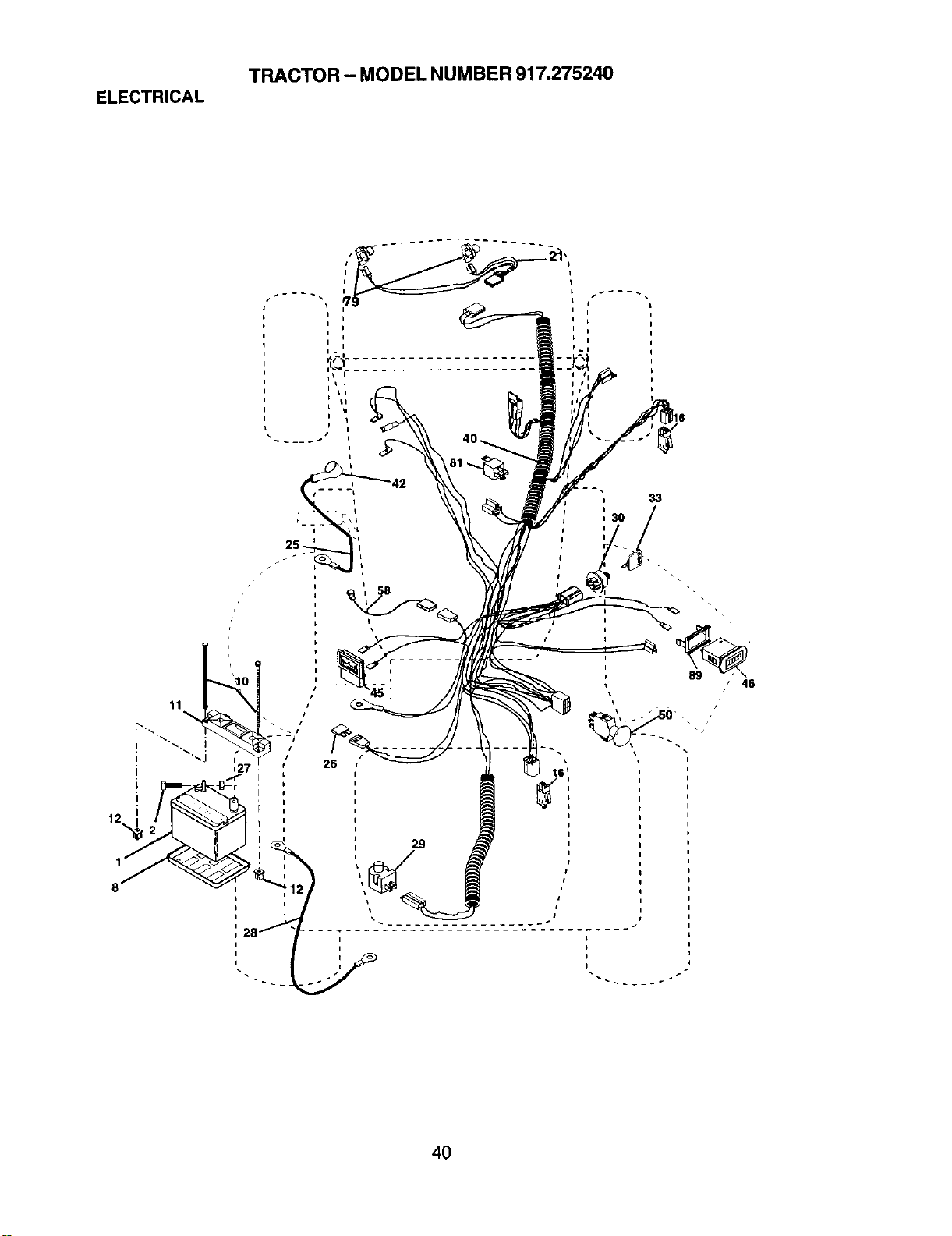
ELECTRICAL
TRACTOR- MODEL NUMBER 917,275240
33
26
4O
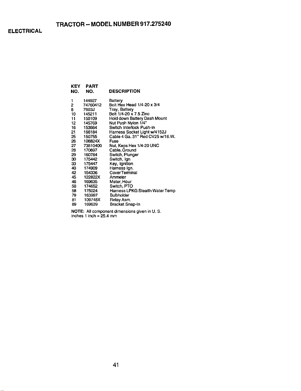
ELECTRICAL
TRACTOR - MODEL NUMBER 917.275240
KEY PART
NO. NO. DESCRIPTION
1 144927 Battery
2 74760412 BoltHex Head 1/4-20 x 3/4
8 7603J Tray, Battery
10 145211 Bolt 1/4-20 x 7.5 Zinc
It 150109 Holddown BatteryDash Mount
12 145769 Nut Push Nylon 1/4"
16 153664 Switch Interlock Push-in
21 166184 Hamese Socket Lightw/4152J
25 150755 Cable 4 Ga. 31" Red CV25 w/16.W.
26 108824X Fuse
27 73510400 Nut, Keps Hex 1/4-20 UNC
28 170697 Cable,Ground
29 160784 Switch,Plunger
30 175442 Switch, Ign
33 175447 Key, Ignition
40 174909 Harness Ign.
42 154336 CoverTerminal
45 122822X Ammeter
46 169635 Meter, Hour
50 174652 Switch, PTO
58 175024 HarnessLPKG StealthWater Temp
79 163997 Bulbholder
81 109748X Relay Asm.
59 169639 Bracket Snap-In
NOTE: All componentdimensionsgiven in U. S.
inches 1inch = 25.4 mm
41
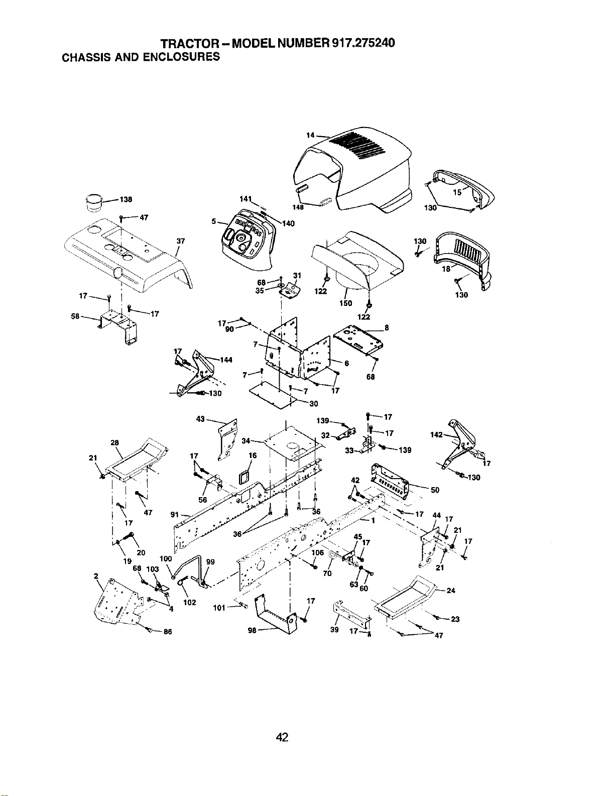
TRACTOR - MODEL NUMBER917.275240
CHASSISAND ENCLOSURES
17
_20
19 100
68
2
86
37
I
179_. •
17 144
17
150
122
17
56
102
70
39
130
42
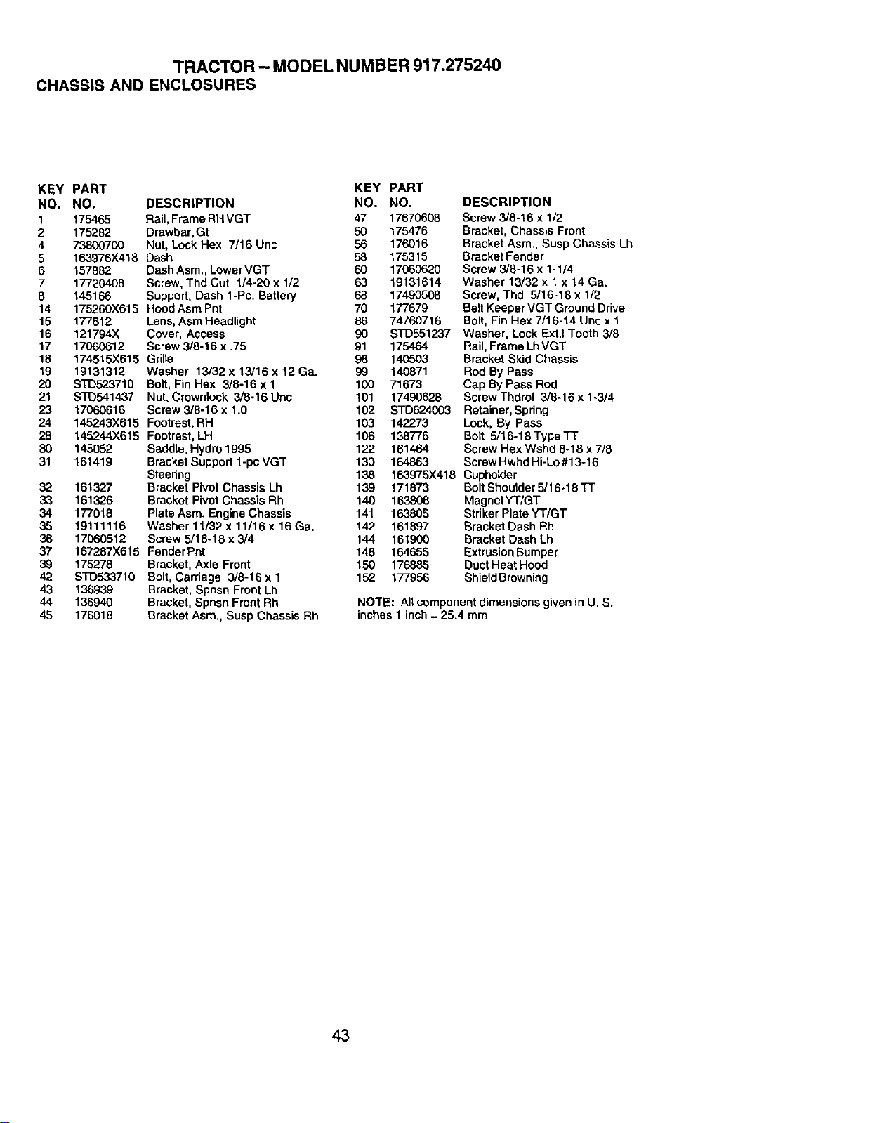
TRACTOR - MODEL NUMBER 917.275240
CHASSIS AND ENCLOSURES
KEY PART KEY PART
NO. NO. DESCRIPTION NO. NO.
1 175465 Rail, Frame RHVGT 47 17670608
2 175282 Drawhar, Gt 50 175476
4 73800700 Nut, Lock Hex 7/16 Unc 56 176016
5 163976X418 Dash 58 175315
6 157882. Dash Asm., Lower VGT 60 17060620
7 17720408 Screw, Thd Cut 1/4-20 x 1/2 63 19131614
8 145166 Support, Dash 1-Pc. Battery 68 17490508
14 175260X615 Hood Asm Pnt 70 177679
15 177612 Lens, Asm Headlight 86 74760716
16 121794X Cover, Access 90
17 17060612 Screw 3/8-16 x .75 91
18 174515X615 Grille 98
19 19131312 Washer 13/32 x 13/16 x 12 Ga. _3
20 STD523710 Bolt, Fin Hex 3/8-16 x 1 100
21 s'rD541437 Nut, Crowntock 3/8-16 Unc 101
23 17060616 Screw 3/8-16 x 1.0 102
24 145243X615 Footrest, RH 103
28 145244X615 Footrest,LH 106
30 145052 Saddle, Hydro 1995 122
31 161419 Bracket Support 1-pc VGT 130
Steering 138
32 161327 Bracket Pivot Chassis Lh 139 171873
33 161326 Bracket Pivot Chassis Rh 140 163806
34 177018 Plate Asm. Engine Chassis 141 163805
35 19111116 Washer 11/32 x 11/16 x 16 Ca. 142 161897
36 17060512 Screw 5/16-18 x3/4 144 161900
37 167287X615 FenderPnt 148 164655
39 175278 Bracket,Axle Front 150 176885
42 S'FD533710 Bolt, Carriage 3/8-16 x 1 152 177956
43 136939 Bracket, Spnsn Front Lh
44 136940 Bracket, Spnsn FrontRh
45 176018 Bracket Asm., Susp Chassis Rh
DESCRIPTION
Screw 3/8-16 x 1/2
Bracket, Chassis Front
Bracket Asm,, Susp Chassis Lh
Bracket Fender
Screw 3/8-16 x 1-1/4
Washer 13/32 x 1x 14 Ga.
Screw, Thd 5/16-18 x 1/2
Belt Keeper VGT Ground Drive
Bolt, Fin Hex 7/16-14 Unc x 1
STD551237 Washer, LockExtJ Tooth 3/8
175464 Rail, Frame LhVGT
140503 Bracket Skid Chassis
140871 Red By Pass
71673 Cap By Pass Rod
17490628 Screw Thdrol 3/8-16 x 1-3/4
STD624003 Retainer, Spring
142273 Lock, By Pass
138776 Bolt 5/16-18 Type TT
161464 Screw Hex Wshd 8-16 x 7/8
164863 Screw Hwhd Hi-Lo #13-18
163975X418 Cupholder
Bolt Shoulder5/16-18 FF
Magnet YT/GT
Striker Plate YT/GT
Bracket Dash Rh
Bracket Dash Lh
Extrusion Bumper
Duct Heat Hood
Shield Browning
NO'rE: All componentdimensions given in U. S.
inches 1 inch =25.4 mm
43
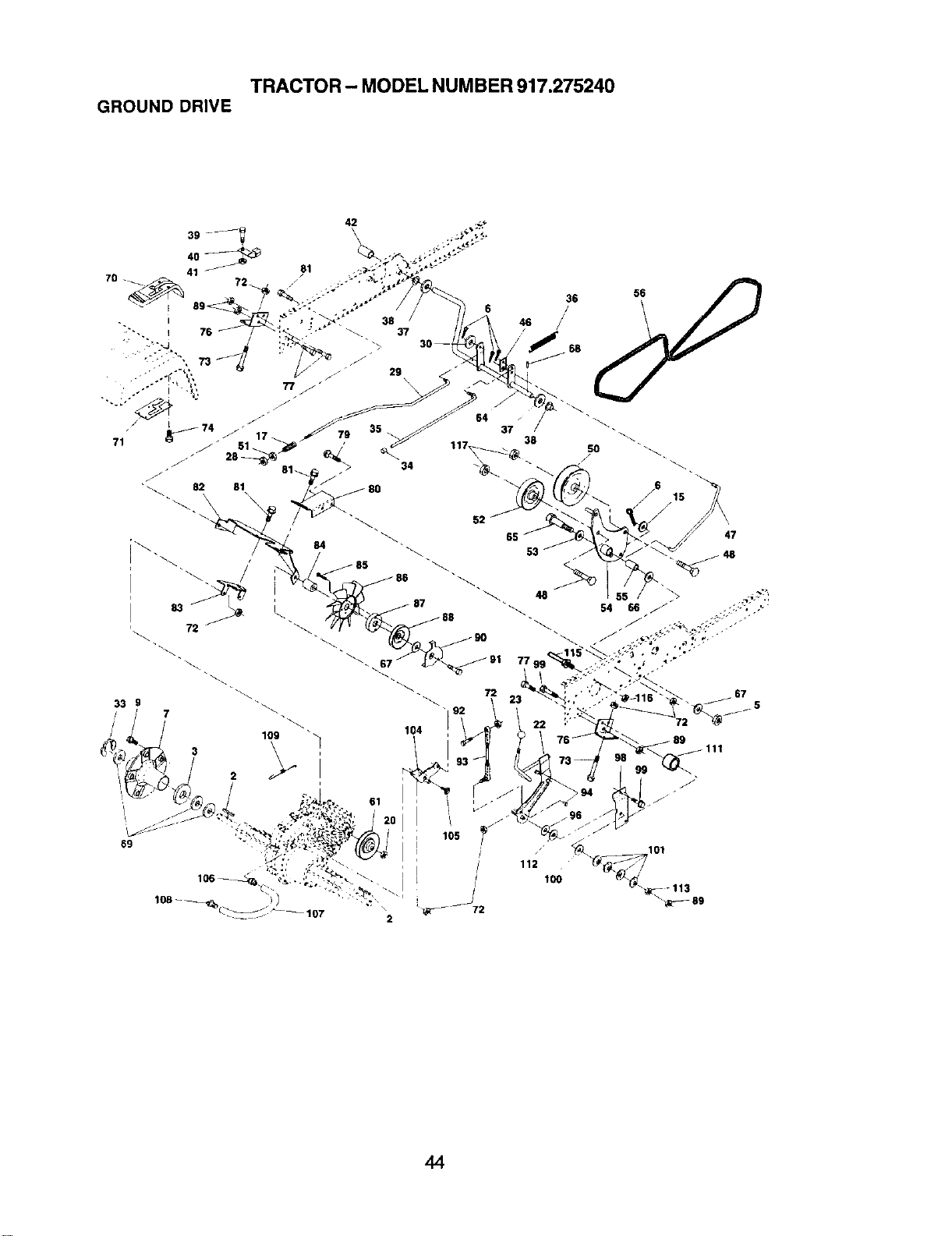
TRACTOR - MODEL NUMBER 917.275240
GROUND DRIVE
42
101
44

TRACTOR - MODEL NUMBER 917.275240
GROUND DRIVE
KEY PART KEY PART
NO. NO. DESCRIPTION NO. NO.
2 7070E Key 1/4 x 2.5 72 STD541431
3 7563R Washer, Thrust, Axle 73 74490548
5 STD541437 Nut, Crownlock 3/8-16 74 142432
6 STD561210 Pin, Cotter 76 140481
7 140507 Wheel, HubAssembly 77 74760716
9 t 40080 Bolt, Hub 79 72110505
15 STD551037 Washer 80 140484
17 140921 Spring 81 17060612
20 73940800 Nut Hex Jam Toplock 1/2-20 82 150586
22 156103 Arm Asm Shift 83 140479
23 130564 Knob 84 140490
28 STD541237 Nut 85 17541020
29 140494 Brake, Rod 86 140462
30 19131616 Washer 13/32 x 1 x 16 Ga. 87 140491
33 12000053 RingE 88 161592
34 71673 Cap, Plunger 89 73680700
35 137648 Rod, Parking Brake 90 140489
36 149412 Spdng, DriveGround 91 17490644
37 121749X Washer 25/32 x 1-1/4 x 16 Ga. 92 74760520
38 150035 Nyliner 93 140502
39 74321016 Screw, Fin. #10-24 x 1 94 133835
40 5304J Actuator, Interlock Switch 96 141103
41 73931000 Nut Centedock 10-24 Unc 98 141004
42 8883R Cover, Pedal 99 17060624
46 145170 Retainer, Spring 100 126881X
47 138228 Clutch ROd 101 156106
48 72110612 Bolt, Carr. 3/8-16 x 1-1/2 Gr. 5 104 140480
50 131494 Pulley, Idler, Flat 105 17580408
51 STD541437 Nut, Crownlock 3/8-16UNC 106 142918
52 139123 Pulley, Idler, Grooved 107 154739
53 207J Washer, Hardened 108 142917
54 161590 Clutch, Arm Assembly 109 140929
55 105706X Bearing, idler 111 156240
56 140218 V-Belt 112 156104
61 140488 Pulley, Transaxle 113 73220700
64 154752 Shaft, Clutch/Brake Pedal 115 123405X
65 67609 Bolt,Shoulder 116 73900500
66 140296 Washer, Hardened 117 73900600
67 19131312 Washer, Flat - - 163198
68 5142H Pin,Roll
69 123800X Washer
70 164892X418 Console Hydro Fender
71 151179 Plate Console Shift
DESCRIPTION
Nut, Crownlock 5/16-18
Bolt Hex Flghd 5/16-18 x 3 Gr5
Screw Hex Wsh. Hi-Lo 1/4-1/2
Bracket Transaxle
Bolt Fin Hex 7/16-14 x 1
Bolt Carriage 5/16-18 x 5/8
Bracket Torque RH
Screw 3/8-16 x 3/4
Bracket Mount Torrque/Fan
StrapTorque Mid
Spacer
Screw #10-24 x 1-1/4
Fan 7" Hydro
Adapter Fan
Pugey Idler
Nut Crownlock 7/16-14 Unc
Keeper Belt
Screw Thdrol 3/8o16x 2-3/4
Bolt Fin Hex 5/16-18 x 1,25
Link Shift Asrn
Fastener Christmas Tree
Washer Nickel Plated
Bracket Shift
Screw 3/8-16 x 1-1/2
Washer Compression
Washer Bellville
Bracket Idler
Screw Tap 1/4-20 x 1/2
O-Ring Asm Hydro Gear 70110
Line Fuel Hydro 15" VGT
Cap Asm Vent Hydro Gear 70109
Spring Return Brake
Spacer Shift Lever VGTH
Washer Nylon High Temp
Nut-HexASF 7/16-14 UNC
Keeper Belt T/A Gnd Dr
Nut Lock Hex Flange 5/16-18
Nut, Lock Fig. 3/8-16
Transaxle (See Breakdown)
Hydro Gear 222-3010
NOTE: All component dimensions given in U. S.
inches 1 inch = 25.4 rnm
45
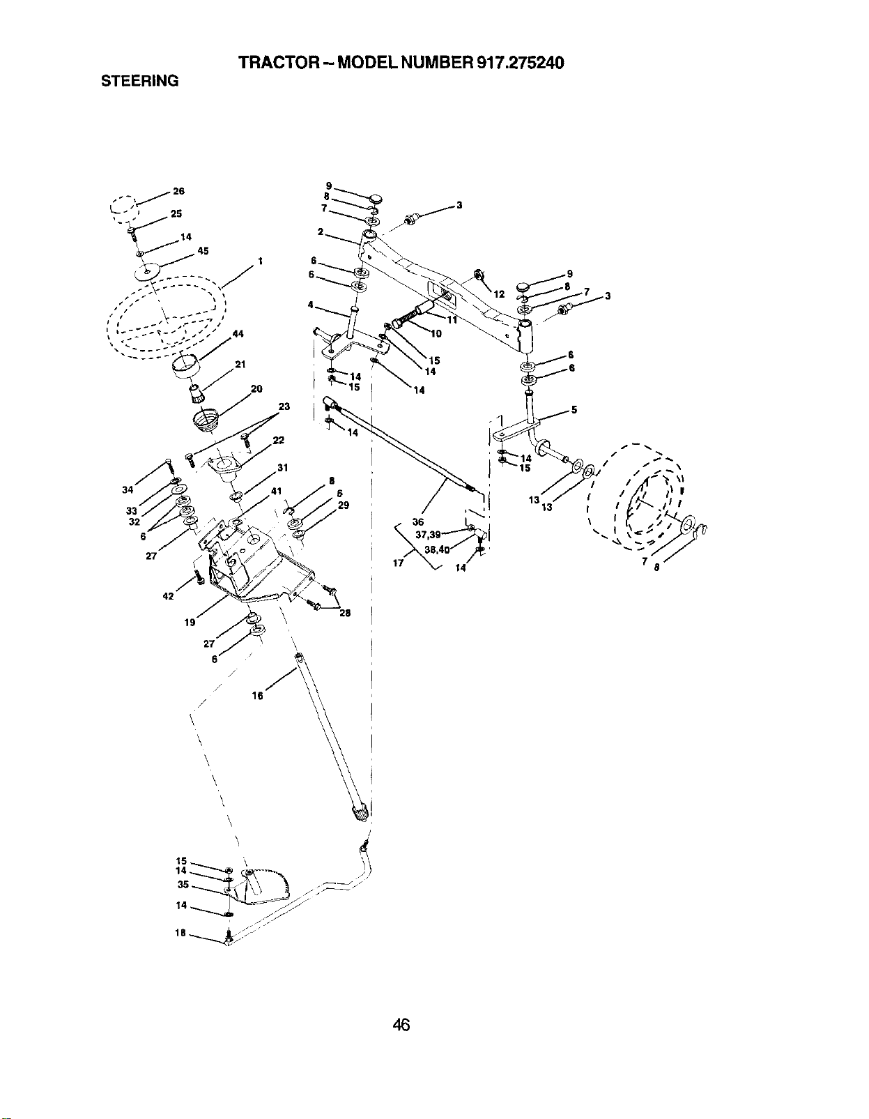
TRACTOR - MODEL NUMBER 917.275240
STEERING
34
32
6
27
42
19
/
X
16
/
\,
\
\
\
\
23
31
15
28
/
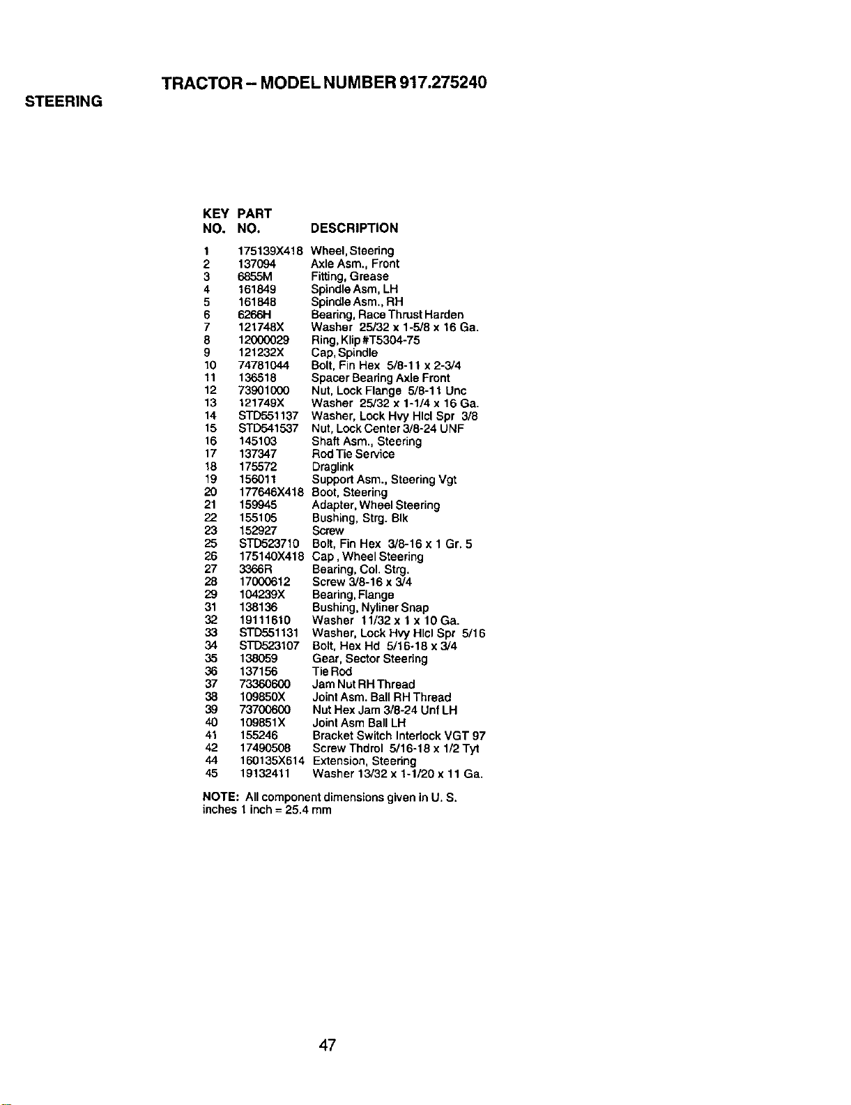
TRACTOR - MODEL NUMBER 917.275240
STEERING
KEY PART
NO. NO. DESCRIPTION
1 175139x418
2 137094
3 6855M
4 161849
5 161848
6 62661-1
7 121748X
8 12000029
9 121232X
10 74781044
11 136518
12 73901000
13 121749)(
14 S'1"D551137
15 STD541537
16 145103
17 137347
18 175572
19 156011
20 177646X418
21 159945
22 155105
23 152927
25 STD523710
26 175140X418
27 3366R
26 17000612
29 104239X
31 138136
32 19111610
33 STD551131
34 STD523107
35 138059
36 137156
37 73360600
38 109850X
39 73700600
40 109851X
41 155246
42 17490508
44 160135X614
45 19132411
Wheel, Steering
Axle Asm., Front
Fitting,Grease
Spindle Asm, LH
Spindle Asm., RH
Bearing, Race Thrust Harden
Washer 25/32 x 1-5/8 x 16 Ga.
Ring, Klip #T5304-75
Cap, Spindle
Bolt, Fin Hex 5/8-11 x 2-3/4
Spacer Bearing Axle Front
Nut, Lock Flange 5/8-11 Unc
Washer 25/32 x 1-1/4 x 16 Ga.
Washer, Lock Hvy Hlcl Spr 3/8
Nut, Lock Center 3/8-24 UNF
Shaft Asm., Steering
Rod Tie Service
Draglink
Support Asm., Steering Vgt
Boot, Steering
Adapter, Wheel Steering
Bushing, Strg. BIk
Screw
Bolt, Fin Hex 3/8-16 x 1 Gr. 5
Cap, Wheel Steering
Bearing, Col. Strg.
Screw 3/8-16 x 3/4
Bearing, Flange
Bushing, Nyliner Snap
Washer 11/32x 1 x 10Ga.
Washer, Lock Hvy Hlcl Spr 5/16
Bolt, Hex Hd 5/16-18 x 3/4
Gear, Sector Steering
Tie ROd
Jam Nut RHThread
JointAsm. BallRH Thread
Nut Hex Jam 3/8-24 Unf LH
JointAsm BallLH
Bracket Switch InterlockVGT 97
Screw Thdrol 5/16-18 x 1/2 Tyt
Extension,Steering
Washer 13/32 x 1-1/20 x 11 Ga.
NOTE: All component dimensionsgiven in U. S.
inches 1 inch = 25.4 mm
47
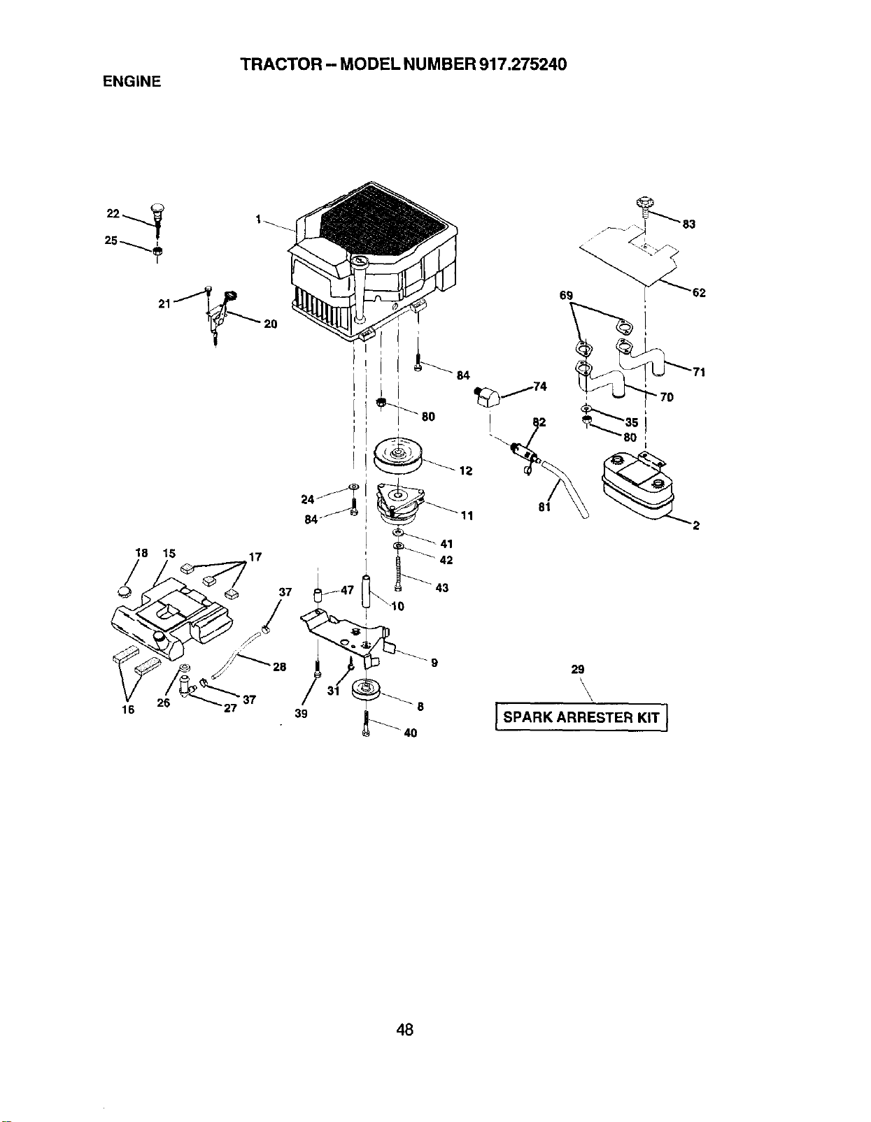
TRACTOR - MODEL NUMBER 917.275240
ENGINE
22_ 1
25
18 15 17
26 "37
16
84 _ L
70i
81 _2
42
43
8
0
29
\
48
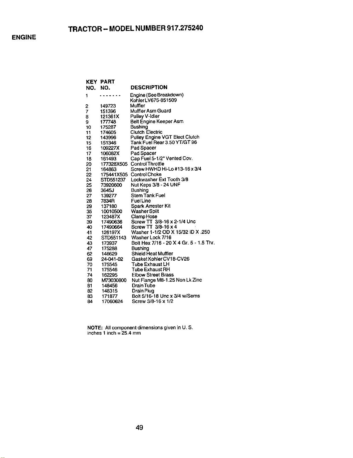
ENGINE
TRACTOR - MODEL NUMBER 917.275240
KEY PART
NO. NO. DESCRIPTION
1
....... Engine(See Breakdown)
KohlerLV675-851509
2 149723 Muffler
7 151396 MufflerAsm Guard
8 121361X PulleyV-Idler
9 177748 Belt Engine KeeperAsm
10 175287 Bushing
11 174605 Clutch Electric
12 143996 PulleyEngineVGT ElectClutch
15 151346 Tank Fuel Rear 3.50 YT/GT 96
16 109227X Pad Spacer
17 106082X Pad Spacer
18 161493 Cap Fuel 5-1/2" Vented Coy.
20 177328X505 ContreIThmttle
21 164863 Screw HWHD Hi-Lo #13-16 x 3/4
22 175441X505 Control Choke
24 STD551237 Lockwasher Ext Tooth 3/6
25 73920600 Nut Keps 3/8 - 24 UNF
26 3645J Bushing
27 139277 Stem Tank Fuel
28 7834R FuelLine
29 137180 Spark Arrester Kit
35 10010500 Washer Split
37 123487X Clamp Hose
39 17490636 Screw 11" 3/8-16 x 2-1/4 Unc
40 17490664 Screw TI" 3/8-16 x 4
41 126197X Washer 1-1/20D X 15/32 ID X .250
42 STD551143 Washer Lock7/16
43 173937 Bolt Hex 7/16 - 20 X 4 Gr. 5 - 1.5 Thr.
47 175288 Bushing
62 146629 Shield Heat Muffler
69 24-041-02 Gasket Kohler CV18-CV26
70 175545 Tube Exhaust LH
71 175546 Tube ExhaustRH
74 162295 ElbowStreet Brass
80 M73030800 Nut Flange M8-1.25 Non Lk Zinc
81 148456 DrainTube
82 148315 Drain Plug
83 171877 Bolt5/16-18 Unc x3/4 w/Sems
84 17060624 Screw 3/8-16 x 1/2
NOTE: All componentdimensions given in U, S.
inches 1 inch = 25.4 mm
49
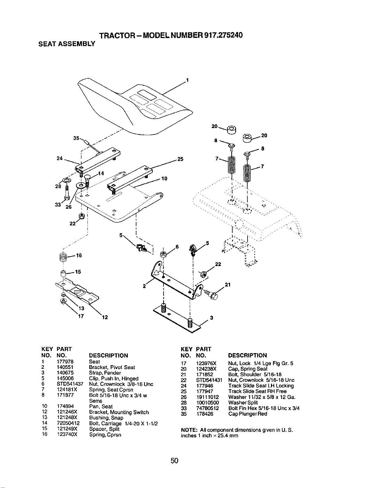
SEATASSEMBLYTRACTOR- MODELNUMBER917.275240
12
7
7
21
KEY PART
NO. NO.
1 177978
2 140551
3 140675
5 145006
6 $1"D541,437
7 124181X
8 171877
10 174894
12 121246X
13 121248X
14 72050412
15 121249X
16 123740X
DESCRIPTION
Seat
Bracket, Pivot Seat
Strap, Fender
Clip, PushIn, Hinged
Nut,Crownlock 3/8-16 Uric
Spring, Seat Cprsn
Bolt 5/16-18 Unc x 3/4 w
Berns
Pan, Seat
Bracket, Mounting Switch
Bushing, Snap
Bolt, Carriage f/4-20 X 1-1/2
Spacer, Split
Spring, Cprsn
KEY PART
NO. NO.
17 123976X
20 124238X
21 171852
22 STD541431
24 177946
25 177947
26 19111012
28 10010500
33 74780512
35 178426
DESCRIPTION
Nut, Lock 1/4 Lge Fig Gr. 5
Cap, SpringSeat
Bolt,Shoulder 5/16-18
Nut,Crownlock 5/16-18 Unc
Track Slide Seat LH Locking
Track Slide Seat RH Free
Washer 11/32 x 5/8 x 12 Ga.
Washer Split
Bolt Fin Hex 5/16-18 Unc x 3/4
Cap Plunger Red
NOTE: All componentdimensions given in U. S.
inches I inch = 25.4 mrn
50
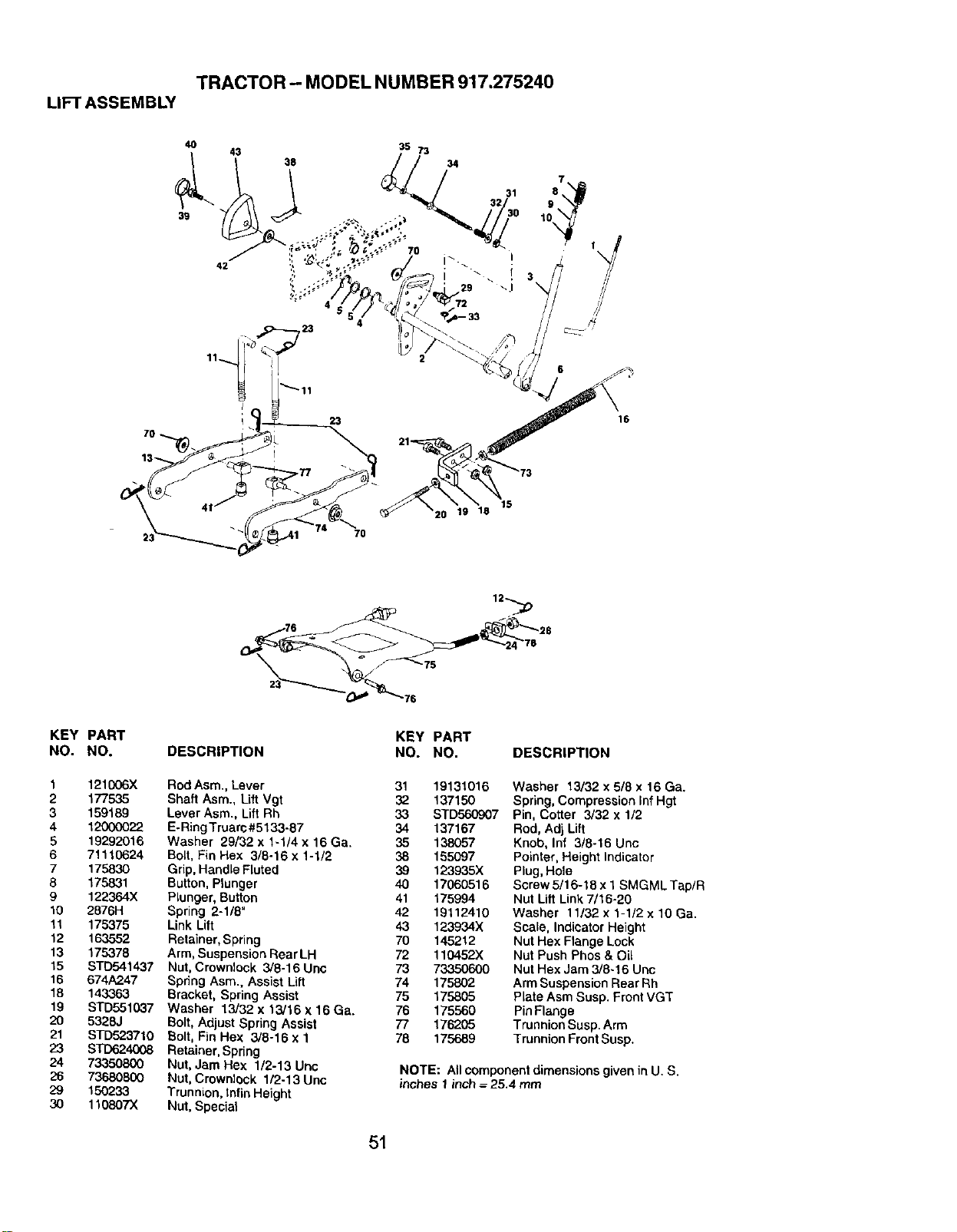
TRACTOR - MODEL NUMBER 917.275240
LIFT ASSEMBLY
23
16
15
20 19 18
7O
__75 78
KEY PART
NO. NO.
1 121006X
2 177535
3 159189
4 12000022
5 19292016
6 71110624
7 175830
8 175831
9 122364X
10 2876H
11 175375
12 163552
13 175378
15 STD541437
16 674A247
18 143363
19 STD551037
20 5328J
21 STD523710
23 STD624008
24 73350800
26 73680800
29 15O233
30 11080TX
DESCRIPTION
Rod Asm., Lever
Shaft Asm., Lift Vgt
Lever Asm., Lift Rh
E-RingTruam#5133-87
Washer 29/32 x 1-1/4 x 16 Ga.
Bolt,Fin Hex 3/8-16 x 1-1/2
Grip,Handle Fluted
Button,Plunger
Plunger, Button
Spring 2-1/8"
Link Lift
Retainer, Spring
Arm, Suspension Rear LH
Nut, Crownlock 3/8-16 Unc
Spring Asm., Assist Lift
Bracket, Spring Assist
Washer 13/32 x 13/16 x 16 Ga.
Bolt,Adjust Spring Assist
Bolt, Fin Hex 3/8-16 x 1
Retainer, Spring
Nut, Jam Hex 1/2-13 Uric
Nut, Crownlock 1/2-13 Unc
Trunnion, tnfin Height
Nut, Special
KEY PART
NO. NO. DESCRIPTION
31 19131016 Washer 13/32 x 5/8 x 16 Ga.
32 137150 Spring,Compression Inf Hgt
33 STD560907 Pin, Cotter 3/32 x 1/2
34 137167 Rod, Adj Lift
35 138057 Knob, Inf 3/8-16 Unc
38 155097 Pointer, Height Indicator
39 123935X Plug,Hole
40 17060516 Straw 5/16-18 x 1 SMGML Tap/R
41 175994 Nut Lift Link 7/16-20
42 19112410 Washer 11/32 x 1-1/2 x 10 Ga.
43 123934X Scale, IndicatorHeight
70 145212 Nut Hex Ftange Lock
72 110452X Nut Push Phos & Oil
73 73350600 Nut Hex Jam 3/8-16 Unc
74 175802 Arm Suspension Rear Rh
75 175805 Plate Asm Susp. Front VGT
76 175560 PinFlange
77 176205 TrunnionSusp. Arm
78 175689 TrunnionFrontSusp.
NOTE: All component dimensions given in U. S.
inches 1inch = 25.4 mm
51
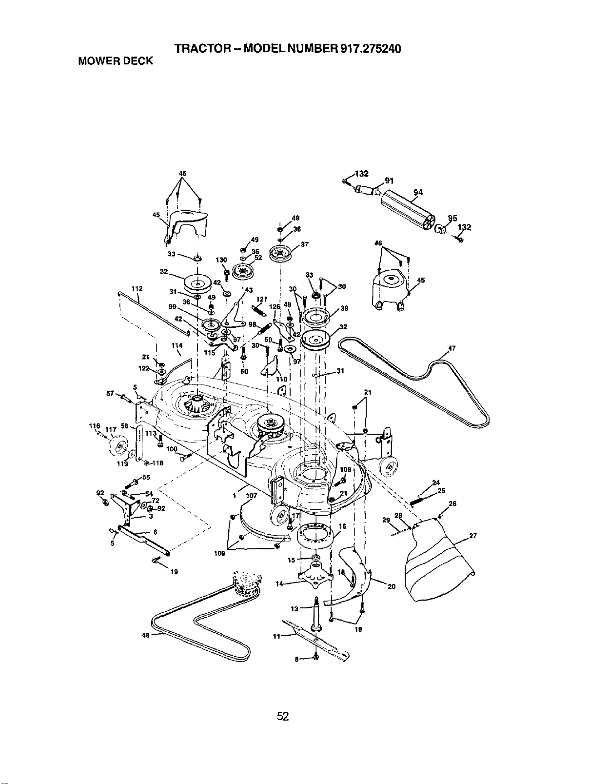
TRACTOR - MODEL NUMBER 917.275240
MOWER DECK
46
112
i 114
21' \
33
94
116
1 107
11_ 18
24
26
52
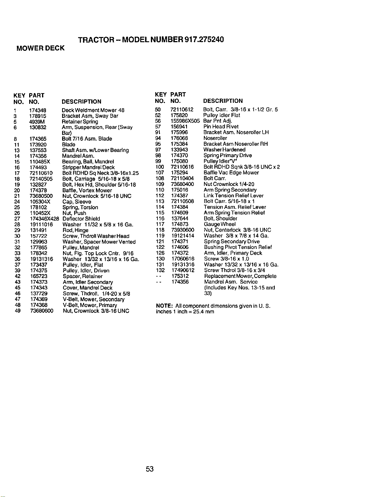
TRACTOR - MODEL NUMBER 917.275240
MOWER DECK
KEY PART KEY
NO. NO. DESCRIPTION NO,
1 174348 DeckWeldment Mower 48 50
3 178915 Bracket Asm, Sway Bar 52
5 4939M Retainer Spring 56
6 130832 Arm, Suspension, Rear (Sway 57 156941
Bar) 91 175996
8 174365 Bolt 7/16 Asm. Blade 94 176066
11 173920 Blade 95 175.384
13 137553 Shaft Asm. w/Lower Bearing 97 133943
14 174356 MandrelAsm. 98 174370
15 110485X Bearing, Ball, Mandrel 99 175080
16 174493 Stdpper Mandrel Deck 100 72110616
17 72110610 Bolt RDHD Sq Neck 3/8-16x1.25 107 175294
18 72140505 Bolt, Carriage 5/16-18x5/8 108 72110404
19 132827 Bolt, Hex Hd, Shoulder 5/16-18 109 73680400
20 174378 Baffle, Vortex Mower 110 175016
21 73680500 Nut, Crownlock 5/16-18UNC 112 174387
24 105304X Cap, Sleeve 113 72110508
25 178102 Spdng, Torsion 114 174384
26 110452X Nut, Push 115 174609
27 174346X428 DeflectorShield 116 137644
28 19111016 Washer 11/32 x 5/8 x 16 Ga. 117 174873
29 131491 Rod, Hinge 118 73930600
30 157722 Screw, Thdroll Washer Head 119 19121414
31 129963 Washer, Spacer Mower Vented 121 174371
32 177865 Pulley,Mandrel 122 174606
33 178342 Nut, Fig. Top Lock Cntr. 9/16 126 174372
36 19131316 Washer 13/32 x 13/16 x 16 Ga. 130 17060616
37 173437 Pulley, Idler, Flat 131 19131316
39 174375 Pulley, Idler, Dnven 132 17490612
42 165723 Spacer, Retainer - - 175312
43 174373 Arm, Idler Secondary - - 174356
45 174343 Cover, MandrelDeck
46 137729 Screw, Thdroll. 1/4-20 x5/8
47 174369 V-Belt, Mower, Secondary
48 174368 V-Belt, Mower, Primary
49 73680600 Nut, Crownlock 3/8-16 UNC
PART
NO. DESCRIPTION
72110612 Bolt, Carr. 3/8-16 x 1-1/2 Gr. 5
175820 Pulley Idler Flat
155986X505 Bar Pnt Adj.
Pin Head Rivet
Bracket Asm. Noseroller LH
Noseroller
BracketAsm NoserollerRH
WasherHardened
Spring PrimaryDrive
PulleyIdler"V"
BoltRDHD Sqnk 3/8-16 UNC x 2
BaffleVac Edge Mower
BoltCam
NutCrownlock1/4-20
Arm SpringSecondary
LinkTension Relief Lever
BoltCarr. 5/16-18 x 1
Tension Asm. ReliefLever
ArmSpringTensionRelief
Bolt,Shoulder
GaugeWheel
Nut, Centerlock 3/8-16 UNC
Washer 3/8 x 7/8 x 14 Ga.
Spring SecondaryDrive
BushingPivotTension Relief
Arm, Idler, Primary Deck
Screw 3/6-16 x 1.0
Washer 13/32 x 13/16 x 16 Ga.
Screw Thdrol 3/6-16 x 3/4
Replacement Mower, Complete
Mandrel Asm. Service
(Includes Key Nos. 13-15 and
33)
NOTE: All component dimensions given in U. S.
inches 1 inch = 25.4 mm
53
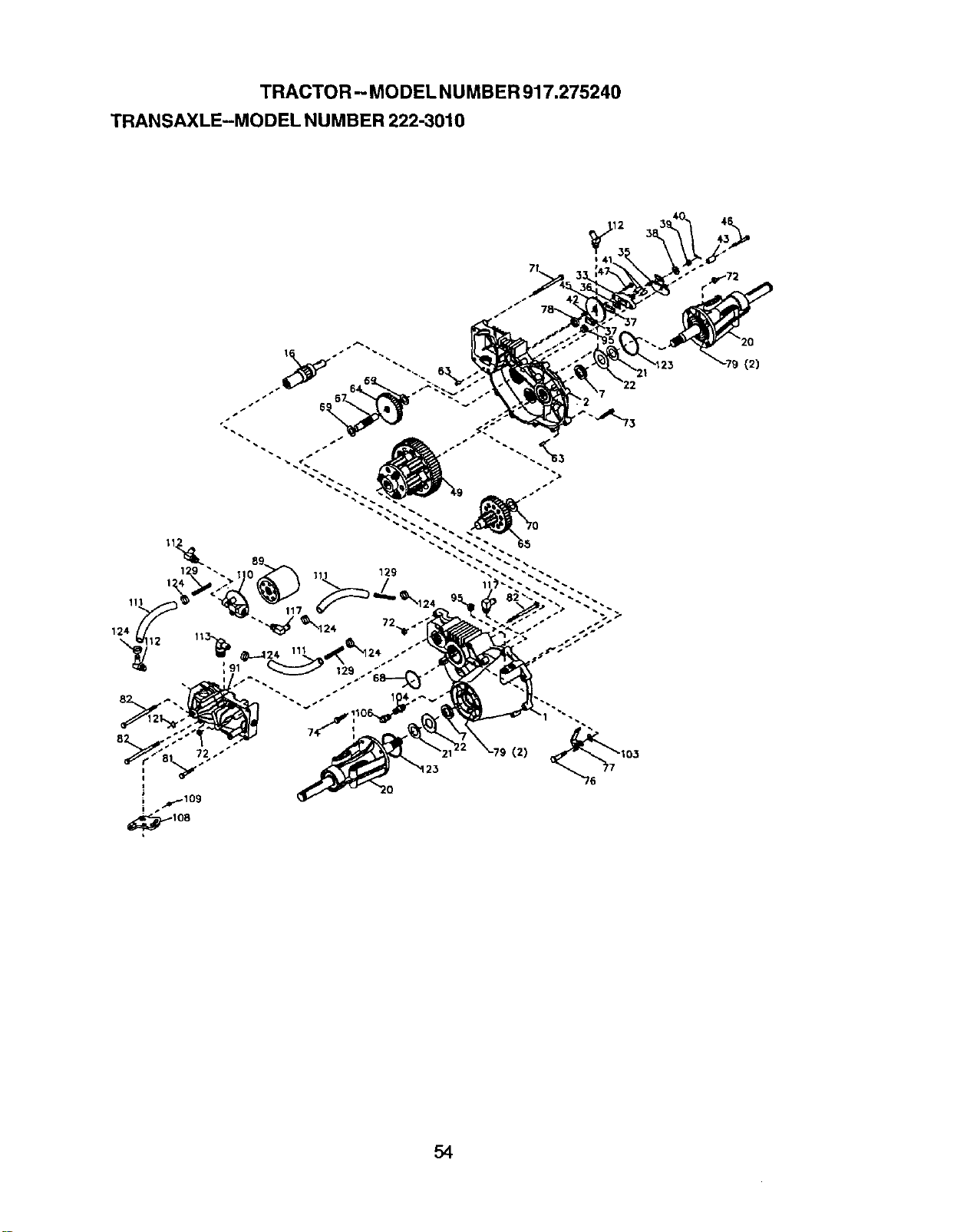
TRACTOR- MODEL NUMBER 917.275240
TRANSAXLE-MODEL NUMBER 222-3010
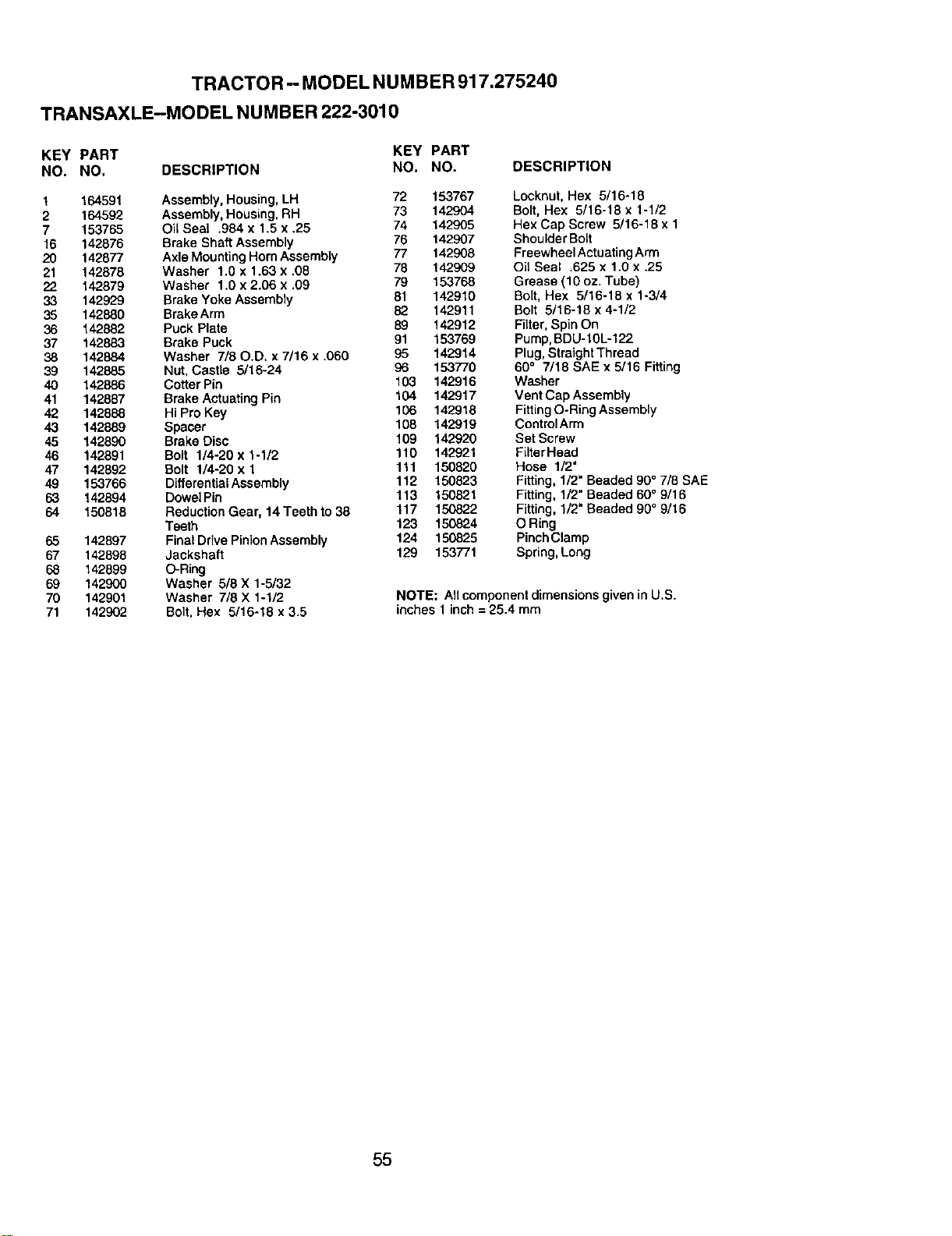
TRACTOR - MODEL NUMBER 917.275240
TRANSAXLE-MODEL NUMBER 222-3010
KEY PART KEY PART
NO. NO. DESCRIPTION NO. NO.
1 164591 Assembly, Housing, LH 72 153767
2 164592 Assembly, Housing,RH 73 142904
7 153765 Oil Seal .984 x 1.5 x .25 74 142905
16 142876 Brake Shaft Assembly 76 142907
20 142877 Axle Mounting Horn Assembly 77 142908
21 142878 Washer 1.6 x 1.63 x .08 78 142909
22 142879 Washer 1.0 x 2.06 x .09 79 153768
33 142929 Brake Yoke Assembly 81 142910
35 142880 BrakeArm 82 142911
36 142882 Puck Plate 89 142912
37 142883 Brake Puck 91 153769
38 142884 Washer 7/80.D. x 7/16 x .060 95 142914
39 142885 Nut, Castle 5/16-24 96 153770
40 142886 Cotter Pin 103 142916
41 142887 Brake Actuating Pin 104 142917
42 142888 Hi Pro Key 106 142918
43 142889 Spacer 108 142919
45 142890 Brake Disc 109 142920
46 142891 Bolt 1/4-20 x 1-1/2 110 142921
47 142892 Bolt 1/4-20 x 1 111 150820
49 153766 Differential Assembly 112 150823
63 142894 Dowel Pin 113 150821
64 150816 Reduction Gear, 14 Teeth to 38 117 150822
Teeth 123 150824
65 142897 Final Drive Pinion Assembly 124 150825
67 142898 Jackshaft 129 153771
68 142899 O-Ring
69 142900 Washer 5/8 X 1-5/32
70 142901 Washer 7/8 X 1-1/2
71 142902 Bolt. Hex 5/16-18 x 3.5
DESCRIPTION
Locknut, Hex 5/16-18
Bolt, Hex 5/16-18 x 1-1/2
Hex Cap Screw 5/16-18 x 1
Shoulder Bolt
Freewheel Actuating Arm
Oil Seal .625 x 1.0 x .25
Grease (10 oz. Tube)
Bolt, Hex 5/16-18 x 1-3/4
Bolt 5/16-18 x 4-1/2
Filter, Spin On
Pump,BDU-10L-122
Plug, Straight Thread
60° 7/18 SAE x 5/16 Fitting
Washer
Vent Cap Assembly
Fitting O-Ring Assembly
ControlArm
Set Screw
Filter Head
Hose 1/2"
Fitting, 1/2" Beaded 90° 7/8 SAE
Fitting, 1/2" Beaded 60° 9/16
Fitting, 1/2" Beaded 90° 9/16
O Ring
Pinch Clamp
Spring, Long
NOTE: All componentdimensions given in U.S.
inches 1inch = 25.4 mm
55
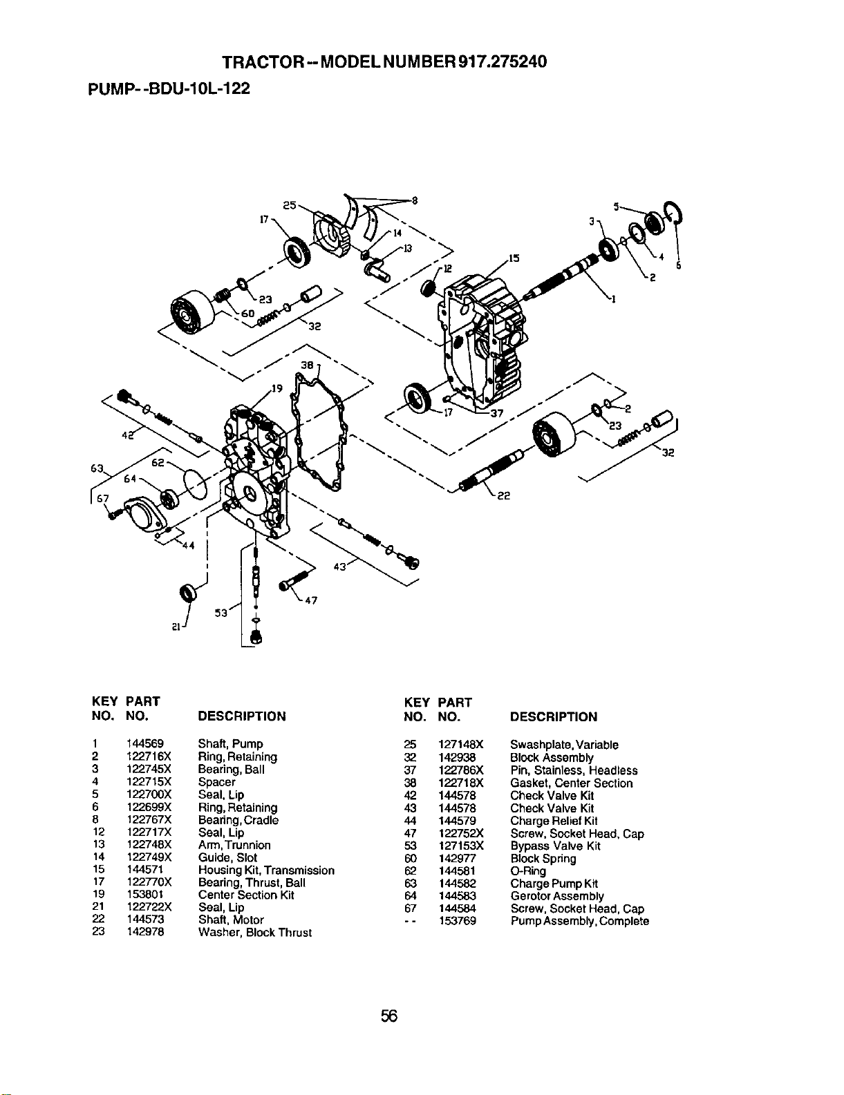
TRACTOR -- MODEL NUMBER 917.275240
PUMP--BDU-10L-122
32
KEY PART
NO, NO.
1 144569
2 122716X
3 122745X
4 122715X
5 122700X
6 122699X
8 122767X
12 122717X
13 122748X
14 122749X
15 144571
17 122T/0X
19 153801
21 122722X
22 144573
23 142978
DESCRIPTION
Shaft, Pump
Ring, Retaining
Bearing, Ball
Spacer
Seal, Lip
Ring,Retaining
Bearing, Cradle
Seal, Lip
Arm, Trunnion
Guide, Slot
Housing Kit,Transmission
Bearing, Thrust, Ball
Center Section Kit
Seal, Lip
Shaft, Motor
Washer, BlockThrust
KEY PART
NO. NO.
25 127148X
32 142938
37 122786X
38 122718X
42 144578
43 144578
44 144579
47 122752X
53 127153X
60 142977
62 144581
63 144582
64 144583
67 144584
- - 15,3769
DESCRIPTION
Swashplate, Variable
Block Assembly
Pin, Stainless, Headless
Gasket, Center Section
Check Valve Kit
Check Valve Kit
Charge Relief Kit
Screw, Socket Head, Cap
Bypass Valve Kit
Block Spdng
O-Ring
Charge Pump Kit
Gerotor Assembly
Screw, Socket Head, Cap
Pump Assembly, Complete
56
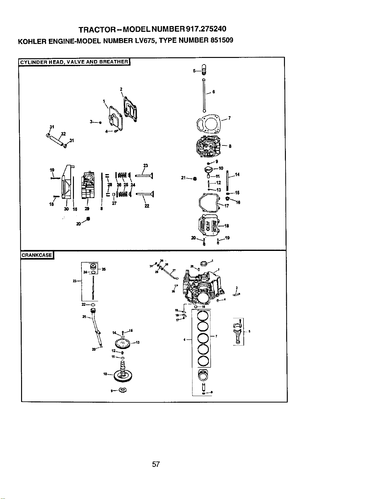
TRACTOR - MODEL NUMBER 917.275240
KOHLER ENGINE-MODEL NUMBER LV675, TYPE NUMBER 851509
CYLINDER HEAD_ VALVE AND BREATHER I
2
1
\
22
30 18 21 8
- 20._
22mo
i Q_13
12..._
10_
w..-9
21_Q 11 14
I-'' U
17 6
20 19
57
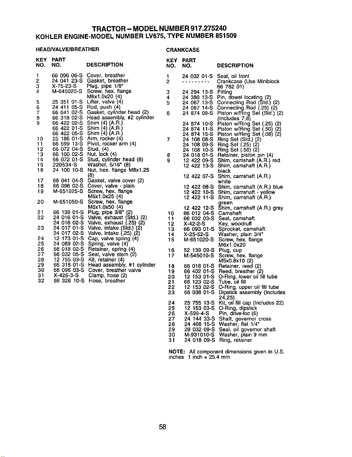
TRACTOR - MODEL NUMBER917.275240
KOHLERENGINE-MODELNUMBERLV675,TYPENUMBER851509
HEAD/VALVE/BREATHER CRANKCASE
KEY PART KEY PART
NO. NO. DESCRIPTION NO. NO. DESCRIPTION
1 66 096 06-S Cover, breather 1 24 032 01-S Seal, oil front
2 24 041 23-S Gasket, breather 2 ......... Crankcase (Use Miniblock
3 X-75-23-S Plug, pipe 1/8" 66 782 01)
4 M-645020-S Screw, hex. flange 3 24 294 13-S Fitting
M6xl.0x20 (4) 4 24 380 13-S Pin, dowel locating (2)
5 25 351 01-S Lifter, valve (4) 5 24 067 t3-S Connecting Rod (Std.) (2)
6 24 411 05-S Rod, push (4) 24 067 14-S Connecting Rod (.25) (2)
7 66 041 02-S Gasket, cylinder head (2) 6 24 874 09-S Piston w/Ring Set (Std.) (2)
8 66 318 02-S Head assembly, #2 cylinder (Includes 7,8)
9 66 422 02-S Shim (4) (A.R.) 24 874 10-S Piston w/Ring Set (.25) (2)
68 422 01-S Shim (4) (A.R.) 24 874 11-S Piston w/Ring Set (.50) (2)
66 422 05-S Shim (4) (A.R.) 24 874 15-S Piston w/Ring Set (.08) (2)
10 25 186 01-S Arm, rocker (4) 7 24 108 08-S Ring Set (Std.) (2)
11 66 599 13-S Pivot, rocker arm (4) 24 108 09-S Ring Set (.25) (2)
12 66 072 04-S Stud, (4) 24 108 t0-S Ring Set (.50) (2)
13 66 100 02-S Nut, lock (4) 8 24 018 01-S Retainer, piston pin (4)
14 66 072 01-S Stud, cylinder head (8) 9 12 422 09-S Shim, camshaft (A.R.) red
15 220534-S Washer, 5116" (8) 12 422 13-S Shim, camshaft (A.R.)
16 24 100 1O-S Nut, hex. flange M8x1.25 black
(8) 12 422 O7-S Shim, camshaft (A.R.)
17 66 041 04-S Gasket, valve cover (2) white
18 66 096 02-S Cover, valve - plain 12 422 08-S Shim, camshaft (A.R.) blue
19 M-651025-S Screw, hex. flange 12 422 10-S Shim, camshaft - yellow
M6x1.0x25 (4) 12 422 11-S Shim, camshaft (A.R.)
20 M-651050-S Screw, hex. flange
M6xl.0x50 (4) 12 422 12-S _reen
him, camshaft (A.R.) gray
21 66 139 01-S Plug, pipe 3/8" (2) 10 66 012 04-S Camshaft
22 24 016 01-S Valve, exhaust (Std.) (2) 11 66 032 03-S Seal, camshaft
24 016 02-S Valve, exhaust (.25) (2) 12 X-42-2-S Key, woodruff
23 24 017 01-S Valve, intake (Std.) (2) 13 66 093 01-S Sprocket, camshaft
24 017 02-S Valve, intake (.25) (2) 14 X-25-52-S Washer, plain 3/4"
24 12 173 01-S Cap, valve spring (4) 15 M-651020-S Screw, hex. flange
25 24 089 02-S Spring, valve (4) M6xl.0x20
26 66 018 02-S Retainer, spring (4) 16 52 139 09-S Plug, cup
27 66 032 05-S Seal, valve stem (2) 17 M-545010-S Screw, hex. flange
28 12 755 03-S Kit, retainer (4) M5x0.8xl0 (2)
29 66 318 01-S Head assembly, #1 cylinder 18 66 018 01-S Retainer, reed (2)
30 66 096 03-S Cover, breather valve 19 66 402 01-S Reed, breather (2)
31 X-426-3-S Clamp, hose (2) 20 12 153 01-S O-Ring, lower oil fill tube
32 66 326 10-S Hose, breather 21 66 123 02-S Tube, oil fill
22 12 153 02-S O-Ring, upper oil fill tube
23 66 038 01-S Dipstick assembly (Includes
24,25)
24 25 755 13-S Kit, oil fill cap (Includes 22)
25 12 153 03-S O-Ring, dipstick
26 X-599-4-S Pin, drive-loc (6)
27 24 144 33-S Shaft, governor cross
28 24 468 15-S Washer, flat 1/4"
29 28 032 09-S Seal, oil governor shaft
30 M-9310t0-S Washer, plain 9 mm
31 24 018 09-S Ring, retainer
NOTE: All componentdimensionsgiven in U.S.
inches 1 inch= 25.4 mm
58
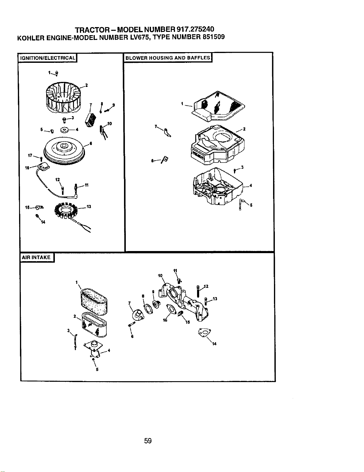
TRACTOR - MODEL NUMBER 917.275240
KOHLER ENGINE-MODEL NUMBER LV675, TYPE NUMBER 851509
IGNITION/ELECTRICAL I BLOWER HOUSING AND BAFFLES I
AIR INTAKE I
8
7
11
lO
4
\
5
16
59
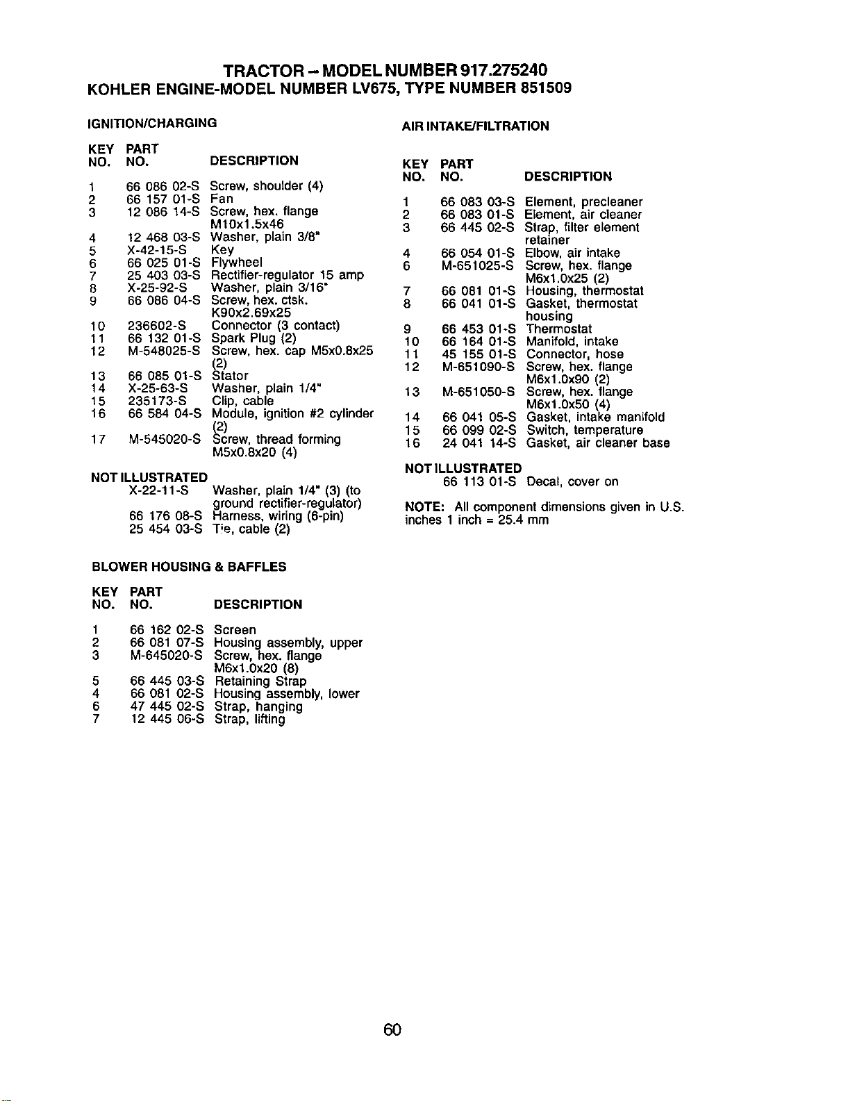
TRACTOR - MODEL NUMBER 917.275240
KOHLER ENGINE-MODEL NUMBER LV675, TYPE NUMBER 851509
IGNITION/CHARGING
KEY PART
NO. NO.
DESCRIPTION
1
2
3
4
5
6
7
8
9
10
11
12
13
14
15
16
17
66 086 02-S
66 157 01-S
12 086 14-S
12 468 03-S
X-42-15-S
66 025 01-S
25 403 03-S
X-25-92-S
66 086 04-S
236602-S
66 132 01-S
M-548025-S
66 085 01-S
X-25-63-S
235173-S
66 584 04-S
M-545020-S
Screw, shoulder (4)
Fan 1
Screw, hex. flange 2
M10x1.5x46 3
Washer, plain 3/8"
Key 4
Flywheel 6
Rectifier-regulator 15 amp
Washer, plain 3/16 = 7
Screw, hex. ctsk. 8
K90x2.69x25
Connector (3 contact) 9
Spark Plug (2) 10
Screw, hex. cap M5x0.8x25 11
(2) 12
Stator
Washer, plain 1/4" 13
Clip, cable
Module, ignition #2 cylinder 14
(2) 15
Screw, thread forming 16
Mhx0.8x20 (4)
NOT ILLUSTRATED
X-22-11-S
66 176 08-S
25 454 03-S
Washer, plain 1/4" (3) (to
ground rectifier-regulator)
Harness, wiring (6-pin)
Tie, cable (2)
AIR INTAKE/FILTRATION
KEY PART
NO. NO. DESCRIPTION
66 083 03-S
66 083 01-S
66 445 02-S
66 054 01-S
M-651025-S
66 081 01-S
66 041 01-S
66 453 01-S
66 164 01-S
45 155 01-S
M-65t090-S
M-651050-S
66 041 05-S
66 099 02-S
24 04! 14-S
Element, precleaner
Element, air cleaner
Strap, filter element
retainer
Elbow, air intake
Screw, hex. flange
M6xl.0x25 (2)
Housing, thermostat
Gasket, thermostat
housing
Thermostat
Manifold, intake
Connector, hose
Screw, hex. flange
M6x1.0x90 (2)
Screw, hex. flange
M6xl.0xhO (4)
Gasket, intake manifold
Switch, temperature
Gasket, air cleaner base
NOTILLUSTRATED
66 113 01-S Decal, cover on
NOTE: Allcomponentdimensions given in U.S.
inches 1 inch= 25.4 mm
BLOWER HOUSING & BAFFLES
KEY PART
NO. NO. DESCRIPTION
1
2
3
5
4
6
7
66 162 02-S Screen
66 081 07-S Housing assembly, upper
M-645020-S Screw, hex. flange
M6xl.0x20 (8)
66 445 03-S Retaining Strap
66 081 02-S Housing assembly, lower
47 445 02-S Strap, hanging
12 445 06-S Strap, lifting
60
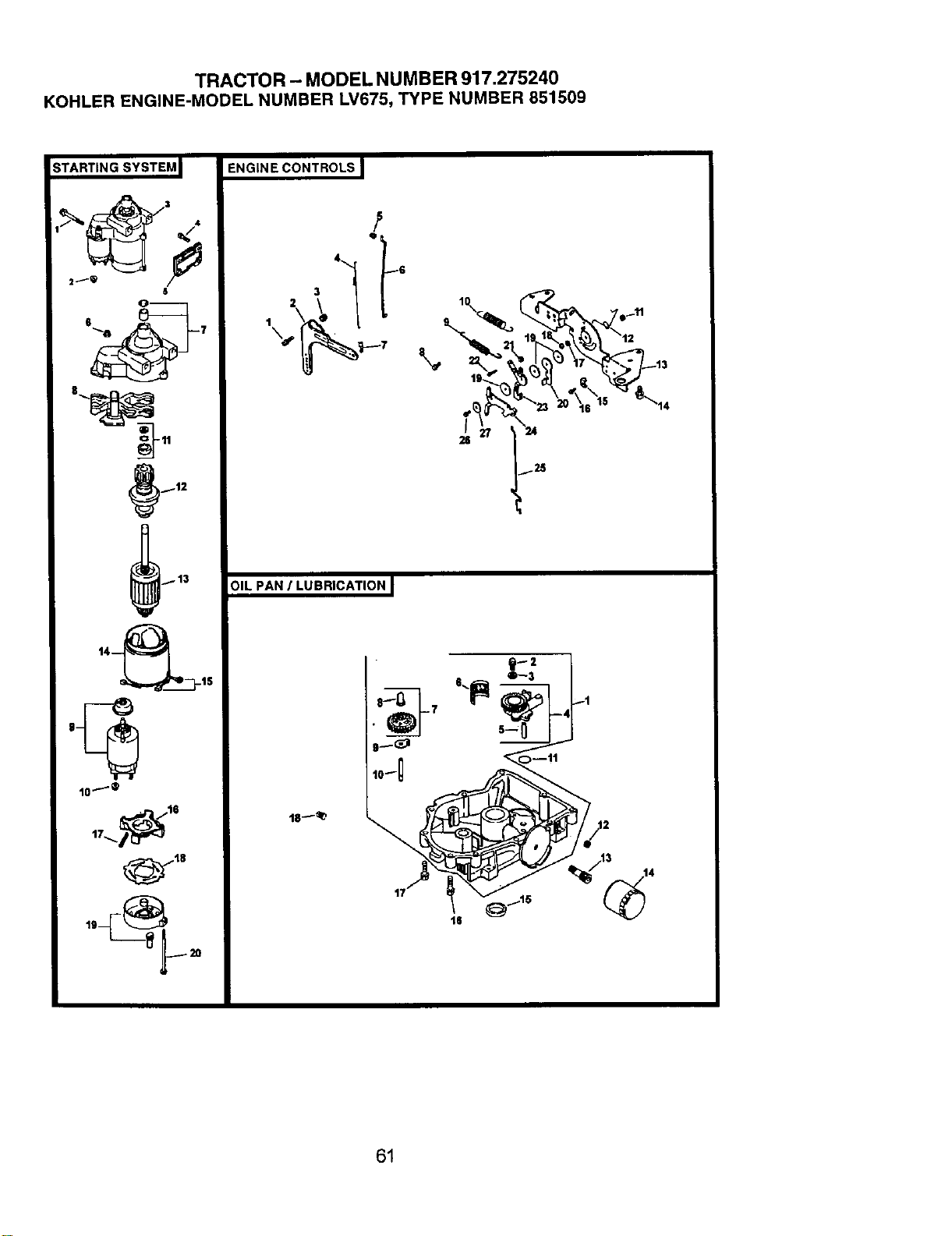
TRACTOR - MODEL NUMBER 917.275240
KOHLER ENGINE-MODEL NUMBER LV675, TYPE NUMBER 851509
;TARTIN G SYSTEM J ENGIN E CONTROLS
/3
2_
6
O--
s _
_--7
._12
ID t
_6
2\ i_ I ,
_2S
,I
10_@
OIL PAN / LUBRICATION I
61
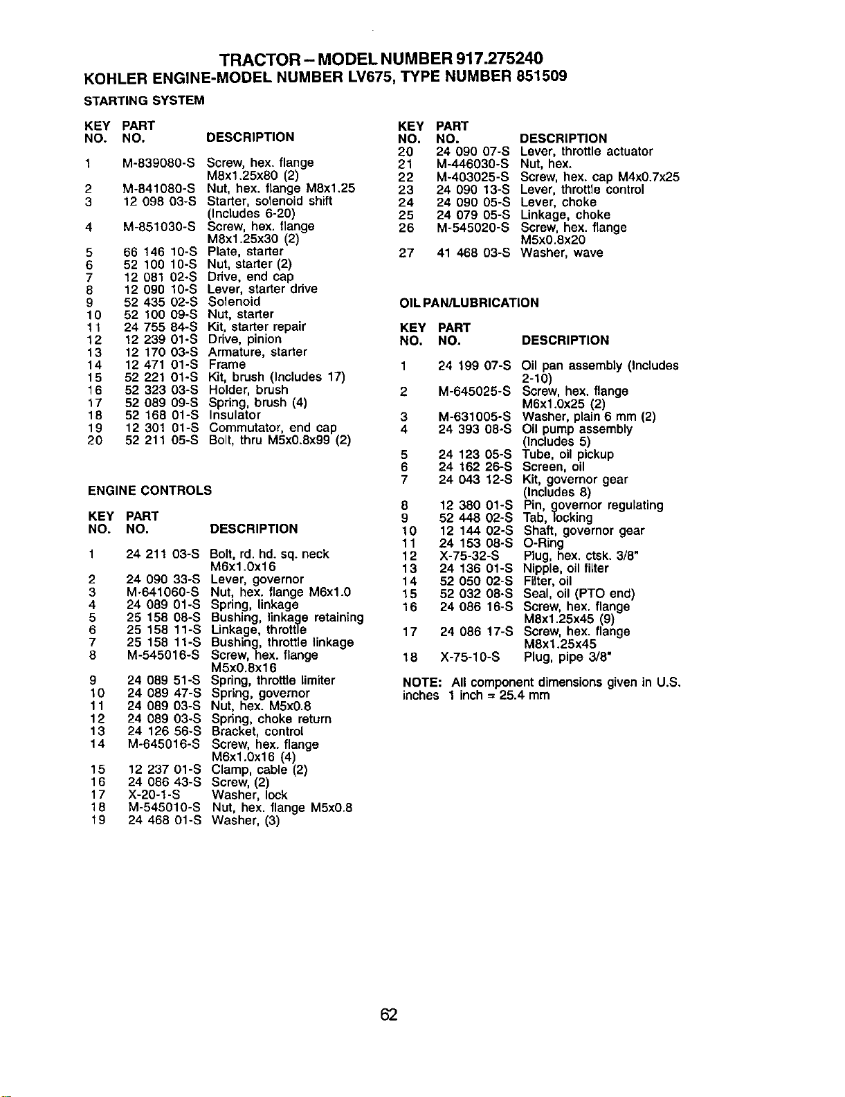
TRACTOR - MODEL NUMBER 917.275240
KOHLER ENGINE-MODEL NUMBER LV675, TYPE NUMBER 851509
STARTING SYSTEM
KEY PART KEY PART
NO. NO. DESCRIPTION
1 M-839080-S Screw, hex. flange
M8x1.25x80 (2)
2 M-841080-S Nut, hex. flange M8x1.25
3 12 098 03-S Starter, solenoid shift
(Inctudes 6-20)
4 M-851030-S Screw, hex. flange
M8x1.25x30 (2)
5 66 146 10-S Plate, starter
6 52 100 10-S Nut, starter (2)
7 12 081 02-S Drive, end cap
8 12 090 10-S Lever, starter drive
9 52 435 02-S Solenoid
10 52 100 09-S Nut, starter
11 24 755 84-S Kit, starter repair
12 12 239 01-S Drive, pinion
13 12 170 03-S Armature, starter
14 12 471 01-S Frame
15 52 221 01-S Kit, brush (Includes 17)
16 52 323 03-S Holder, brush
17 52 089 09-S Spring, brush (4)
18 52 168 Ol-S Insulator
19 12 301 01-S Commutator, end cap
20 52 211 05-S Bolt, thru MSx0.8x99 (2)
ENGINE CONTROLS
KEY PART
NO. NO. DESCRIPTION
2
3
4
5
6
7
8
9
10
11
12
13
14
15
16
17
18
19
24 211 O3-S
24 090 33-S
M-641060-S
24 089 01-S
25 158 08-S
25 158 11-S
25 158 11-S
M-545016-S
24 089 51-S
24 089 47-S
24 089 O3-S
24 089 03-S
24 126 56-S
M-645016-S
12 237 01-S
24 086 43-S
X-20-1-S
M-545010-S
24 468 01-S
Bolt, rd. hd. sq. neck
M6x1.0x16
Lever, governor
Nut, hex. flange M6xl.0
Spring, linkage
Bushing, linkage retaining
Linkage, throttle
Bushing, throttle linkage
Screw, hex. flange
M5x0.Sx16
Spring, throttle limiter
Spring, governor
Nut, hex. M5x0.8
Spring, choke return
Bracket, control
Screw, hex. flange
M6x1.0x16 (4)
Clamp, cable (2)
Screw, (2)
Washer, lock
Nut, hex. flange M5x0.8
Washer, (3)
NO. NO. DESCRIPTION
20 24 090 O7-S Lever, throttle actuator
21 M-44603O-S Nut, hex.
22 M-403025-S Screw, hex. cap M4x0.7x25
23 24 090 13-S Lever, throttle control
24 24 090 O5-S Lever, choke
25 24 079 05-S Linkage, choke
26 M-545020-S Screw, hex. flange
M5x0.8x20
27 41 468 03-S Washer, wave
OIL PAN/LUBRICATION
KEY PART
NO. NO. DESCRIPTION
3
4
5
6
7
8
9
10
11
12
13
14
15
16
17
18
24 199 07-S
M-645025-S
M-631605-S
24 393 08-S
24 123 05-S
24 162 26-S
24 043 12-S
12 386 61-S
52 448 O2-S
12 144 02-S
24 153 08-S
X-75-32-S
24 136 01-S
52 060 02-S
52 032 O8-S
24 086 16-S
24 086 17-S
X-75-10-S
Oil pan assembly (Includes
2-10)
Screw, hex. flange
M6x1.0x25 (2)
Washer, plain 6 mm (2)
Oil pump assembly
(Includes 5)
Tube, oil pickup
Screen, oil
Kit, governor gear
(Includes 8)
Pin, governor regulating
Tab, locking
Shaft, governor gear
O-Ring
Plug, hex. ctsk. 3/8"
Nipple, oil filter
Filter, oil
Seal, oil (PTO end)
Screw, hex. flange
M8x1.25x45 (9)
Screw, hex. flange
M8xl.25x45
Plug, pipe 3/8"
NOTE: All componentdimensionsgiven in U.S,
inches 1 inch= 25.4 mm
62
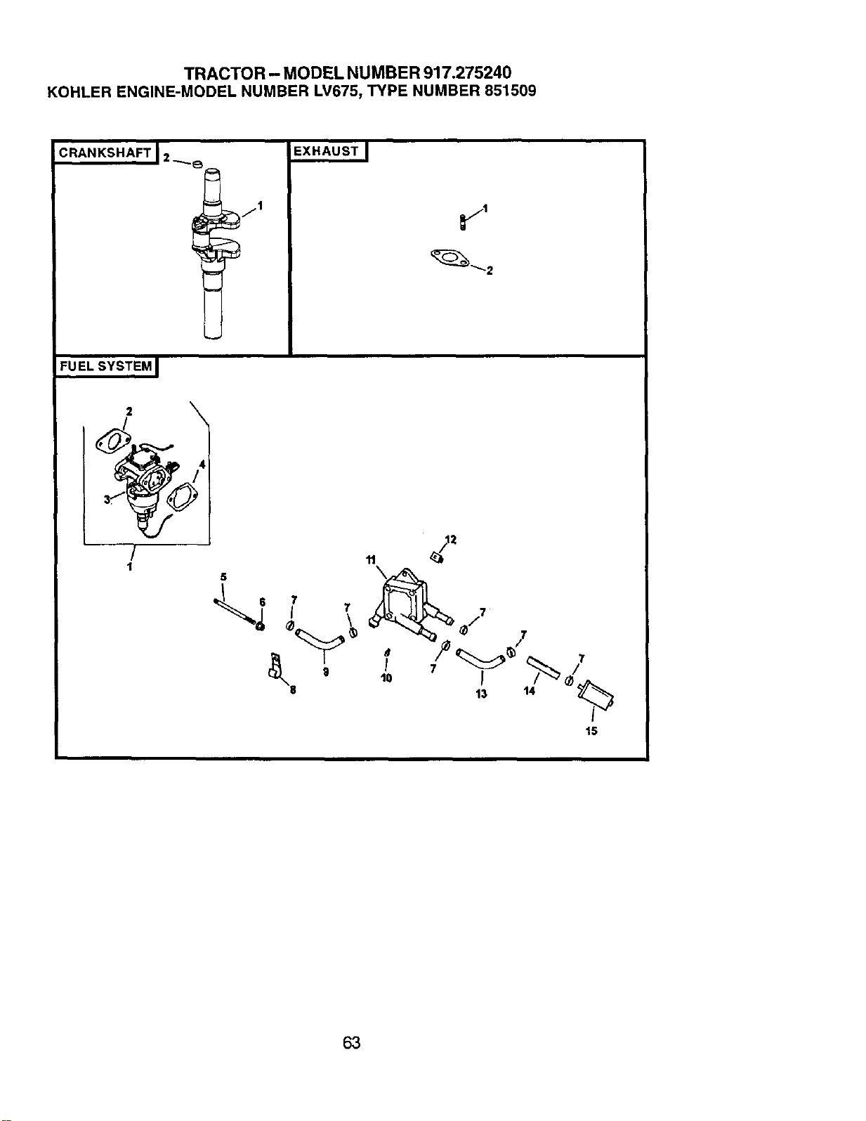
TRACTOR - MODEL NUMBER 917.275240
KOHLER ENGINE-MODEL NUMBER LV675, TYPE NUMBER 851509
¢,,.KS"'FTI._!
F,UELs_sTE_I
!
1
EXHAUST I
7
15
63
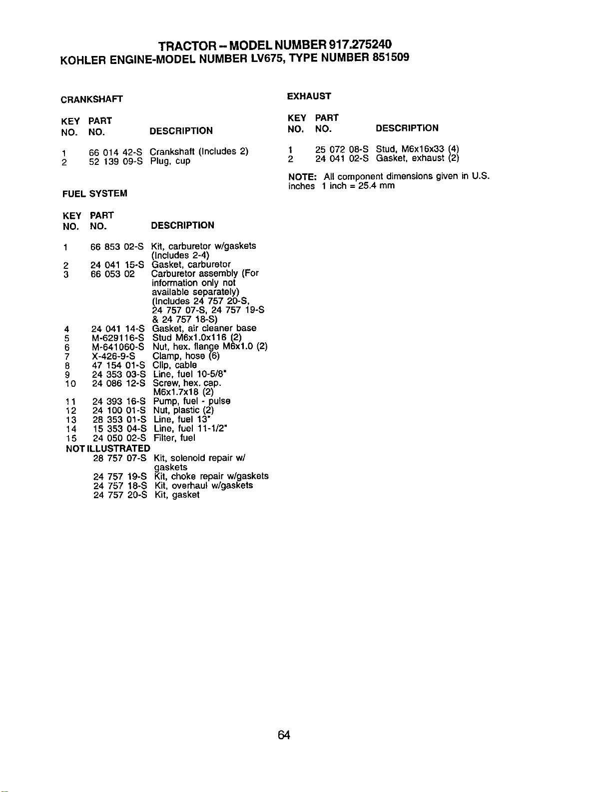
TRACTOR - MODEL NUMBER917.275240
KOHLERENGINE-MODELNUMBERLV675,TYPENUMBER851509
CRANKSHAFT
EXHAUST
KEY PART KEY PART
NO. NO. DESCRIPTION NO. NO. DESCRIPTION
66 014 42°S Crankshaft (Includes 2)
52 139 09-S Plug, cup
FUEL SYSTEM
DESCRIPTION
KEY PART
NO. NO.
1
2
3
4
5
6
7
8
9
10
66 853 02-S
24 041 15-S
66 053 02
24 041 14-S
M-629116-S
M-641060-S
X-426-9-S
47 154 01-S
24 353 03-S
24 086 12-S
24 393 16-S
24 100 01-S
28 353 01-S
15 353 O4-S
Kit, carburetor w/gaskets
(Includes 2-4)
Gasket, carburetor
Carburetor assembly (For
information only not
available separately)
(Includes 24 757 20-S,
24 757 07-S, 24 757 19-S
& 24 757 18-S)
Gasket, air cleaner base
Stud M6x1.0xt16 (2)
Nut, hex. flange M6xl.0 (2)
Clamp, hose (6)
Clip, cable
Line, fuel 10-5/8"
Screw, hex. cap.
M6x1.Tx18 (2)
Pump, fuel - pulse
Nut, plastic (2)
Line, fuel 13"
Line, fuel 11-1/2"
11
12
13
14
15 24 050 02-S Filter, fuel
NOT ILLUSTRATED
28 757 07-S Kit, solenoid repair w/
gaskets
24 757 19-S Kit, choke repair w/gaskets
24 757 18-S Kit, overhaul w/gaskets
24 757 20-S Kit, gasket
25 072 08-S Stud, M6x16x33 (4)
24 041 02-S Gasket, exhaust (2)
NOTE: All component dimensions given in U.S.
inches 1 inch = 25.4 mm
64
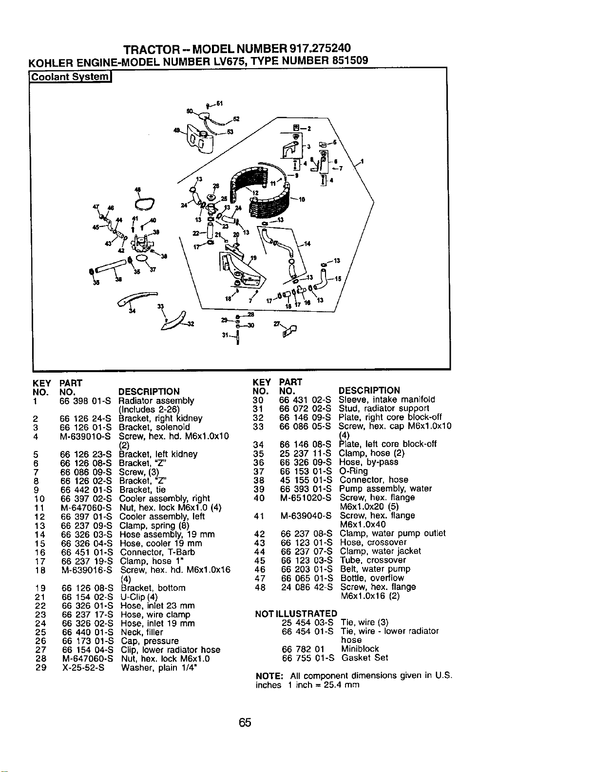
TRACTOR - MODEL NUMBER 917.275240
KOHLER ENGINE-MODEL NUMBER LV675, TYPE NUMBER 851509
Coolant Systeml
KEY PART
NO. NO.
1 66 398 01-S
2 66 126 24-S
3 66 126 Ol-S
4 M-639010-S
5 66 126 23-S
6 66 126 O8-S
7 66 086 09-S
8 66 126 O2-S
9 66 442 01-S
1O 66 397 02-S
11 M-647060-S
12 66 397 01-S
13 66 237 O9-S
14 66 326 03-S
15 66 326 04-S
16 66 451 01-S
17 66 237 19-S
18 M-639016-S
19 66 126 08-S
21 66 154 O2-S
22 66 326 01-S
23 66 237 17-S
24 66 326 02-S
25 66 440 01-S
26 66 173 01-S
27 66 154 O4-S
28 M-647060-S
29 X-25-52-S
KEY PART
DESCRIPTION NO. NO.
Radiator assembly 30 66 431 02-S
(Includes 2-26) 31 66 072 O2-S
Bracket, right kidney 32 66 146 09-S
Bracket, solenoid 33 66 086 05-S
Screw, hex. hd. M6xl.0xlO
(2) 34 66 146 08-S
Bracket, left kidney 35 25 237 11-S
Bracket, =Z" 36 66 326 09-S
Screw, (3) 37 66 153 01-S
Bracket, "Z" 38 45 155 01-S
Bracket, tie 39 66 393 Ol-S
Cooler assembly, right 40 M-651020-S
Nut, hex. lock M6xl.0 (4)
Cooler assembly, left 41 M-639040-S
Clamp, spring (8)
Hose assembly, 19 mm 42 66 237 06-S
Hose, cooler 19 mm 43 66 123 01-S
Connector, T-Barb 44 66 237 07-S
Clamp, hose 1" 45 66 123 03-S
Screw, hex. hd. M6x1.0x16 46 66 203 01-S
(4) 47 66 065 01-S
Bracket, bottom 48 24 086 42-S
U-Clip (4)
Hose, inlet 23 mm
Hose, wire clamp
Hose, inlet 19 mm
Neck, filler
Cap, pressure
Clip, lower radiator hose
Nut, hex. lock M6xl.0
Washer, plain 1/4"
DESCRIPTION
Sleeve, intake manifold
Stud, radiator support
Plate, right core block-off
Screw, hex. cap M6xl.0xl0
(4)
Plate, left core block-off
Clamp, hose (2)
Hose, by-pass
O-Ring
Connector, hose
Pump assembly, water
Screw, hex. flange
M6xl.0x20 (5)
Screw, hex. flange
M6x1.0x40
Clamp, water pump outlet
Hose, crossover
Clamp, water jacket
Tube, crossover
Belt, water pump
Bottle, overflow
Screw, hex. flange
M6xl.0x16 (2)
NOT ILLUSTRATED
25 454 03-S Tie, wire (3)
66 454 01-S Tie, wire - lower radiator
hose
66 782 01 Miniblock
66 755 01-S Gasket Set
NOTE: All component dimensions given in U.S.
inches 1 inch = 25.4 mm
65


SUGGESTED GUIDE FOR SIGHTING SLOPES FOR SAFE OPERATION
SIGHTING -_ .CUT-
GUIDE TH_
ONLY RIDE UP AND DOWN HILL,
NOT ACROSS HILL
O3
_4
A
I
Operate your Tractor up and down the face of slopes (not I
greater than 15 ), never across the face. Make turns gradu-
I
ally to prevent tipping or loss of control. Exercise extreme
caution when changing direction on slopes.

For repair of carry-in products like vacuums, lawn equipment, and
electronics, call for the nearest Sears Parts and Repair Center.
1-800-488-1222 Any'm_, dayor night(U.S.A.only)
www.searsJ_11
For the replacement parts, accessories and owner's manuals
that you need to do-it-yourself,call Sears PartsDirectSM!
1-800-366-PART 6a.m.-11 p.m., 7days aweek
(1-800-366-7278) (U.S_.only)
www.sears.co_rect
To purchase or inquire about a Sears Service Agreement
or Sears Maintenance Agreement:
1-800-827-6655 (u.s_) 1-800-361-6665 (Canada)
7 a.m.- 5 p.m.,CST,Mor_- Sat. 9 a.m.- 8 p.m.EST, M- F,4 p.m.Sat.
Para pedirsewk:_ de reparaci6na
domicilio,y pare.ordenarpiezas:
1-888-SU4-IOGAR_
(1-888-784-6427)
Au _ pourserviceen _:
1.8(XH.E-FOYERMc
(1-800-533-6_37)
www.sears.ca
©Sea_ aoebu_andCo.
® Registered Trademark / TMTrademark / SMService Mark of Sears, Roebuck and Co.
® Marca Registrada / TMMama de Fdbrica / SMMarca de Servicio de Sears, Roebuck and Co.
MCMarque de commerce / aD Marque d_pos_e de Sears, Roebuck and Co.
177812 Rev.6 8.23.01 RD Printed in U.S.A.


