
F760 v1.2
1
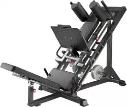
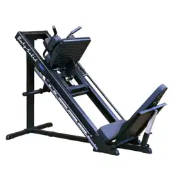
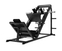
Linear Leg Press / Hack Squat
F760
Owner’s Manual
Base Serial Number: _ _ _ _ _ _ _ _ _ _ _ _ _
Purchased Date: ___ / ___ / ______
Dealer’s Name:__________________________
Please register your products at:
https://www.bodycraft.com/product-registration/
Open your Camera
App and point it at
the QR Code
To see in
FULL COLOR
& additional information,
scan this QR code.

Congratulations and Welcome to the BODYCRAFT Family
Thank you for selecting BODYCRAFT. Your choice reflects a wise investment in you and your
facility. We hope you use it for many healthy years!
BODYCRAFT offers a complete array of high-quality fitness equipment. Please refer to our website at
www.bodycraft.com to view more ways to enhance your lifestyle.
Your BODYCRAFT machine has all the quality and design elements to make your workout extremely efficient
and comfortable. Your new unit is a serious strength training machine that will keep you motivated,
challenged and within reach of your fitness goals. Strength & cardiovascular training is vital for all ages which
will provide an effective workout, producing results that will encourage you to reach your fitness goals and
maintain the body you have always wanted.
Spending 15 to 30 minutes a day, three times a week, is all you need to start seeing the benefits of
a regular exercise program.
As a premium exercise equipment manufacturer, we are committed to your complete satisfaction. If you
have questions, suggestions or find missing or damaged parts, we guarantee your complete satisfaction
through our authorized dealer network or by contacting us directly. Please call your local dealer or
BODYCRAFT.
BODYCRAFT (a division of Recreation Supply, Inc.)
7699 Green Meadows Dr.
Lewis Center, OH 43035
Phone: 800-990-5556 9 am - 5 pm EST Email: service@bodycraft.com
Proof of purchase must be supplied to validate warranty and the product must have been
registered with BODYCRAFT via online at www.bodycraft.com or by calling 800-990-5556
or 740-965-2442 M-F 9 a.m. - 5 p.m. EST.
For parts orders, owner’s manuals, software
update files, exercise guides and contact
information scan this QR code.
Or go to:
https://www.bodycraft.com/customer-support

Product Safety Information
Product Safety ……………………………………………………………...
Important Notes, Recommended Tools & Cleaners ……………………..
Warning Labels, Maintenance Schedule - Details……………….………..
Warning Labels, Maintenance Schedule - Placements ……………………,.
Product Overview
Machine & Shipping Dimensions w/ Weight Capacities ……………………
Assembly Parts List …………………………………………………………
Assembly Parts Hardware …………………………………………………..
Product Assembly - How to Assemble to F760 Leg Press / Hack Squat
PreAssembly Tips ………………………………………………………....
STEP 1a thru STEP 5d - Main Assembly Procedures …………………...
STEP 6 - Final Assembly Clean Up, Polish & Double Checks ……….
Maintenance & Repairs
Detailed Parts List .………….……………………………………….……..
Parts Exploded View .………………………………….……………………
Strength Maintenance & Routine Schedule ………………………….…
Strength Maintenance - Lubrication………………….……………………
Required Info BEFORE Initiating a Service Case ………………………
Warranty
Product Warranty ..........................................................….……...……...
Product Warranty Registration ............................................….….……...
Contact Us Information ……………………………………………………..
3
Table of Contents
NOTE: When you have downloaded the Owner’s Manual into a PDF reader, go directly
to the desired page by touching any words in this Table of Contents.
Page
4
5
6
7
8
9
10
11
12 - 19
20
21 - 22
23 - 24
25
26
27
28
29
30
There is a risk assumed by individuals who use this type of equipment.
A moment’s lack of attention can result in an accident, as can failure to
observe certain simple safety precautions.
Read, study and understand the Assembly Instructions and all the warning labels on
this product. Furthermore, it is recommended to familiarize yourself and others with
the proper operation and workout recommendations for this BODYCRAFT product
prior to use.
● Before beginning this or any other exercise program, consult your physician. This is
especially important for individuals over the age of 35 or persons with preexisting health
problems. Recreation Supply, Inc. assumes no responsibility for personal injury or
property damage sustained by or through use of this product.
● Exercise with care to avoid injury. Do not attempt to lift more weight than you can control
safely.
● This product must be assembled on a flat, level surface to assure its proper function.
● Clean pads and frame on a regular basis. We recommend warm, soapy water. Do not
use harsh or abrasive chemicals.
● Inspect and tighten all parts before every use. Replace any worn parts immediately.
Failure to do so may result in serious injury.
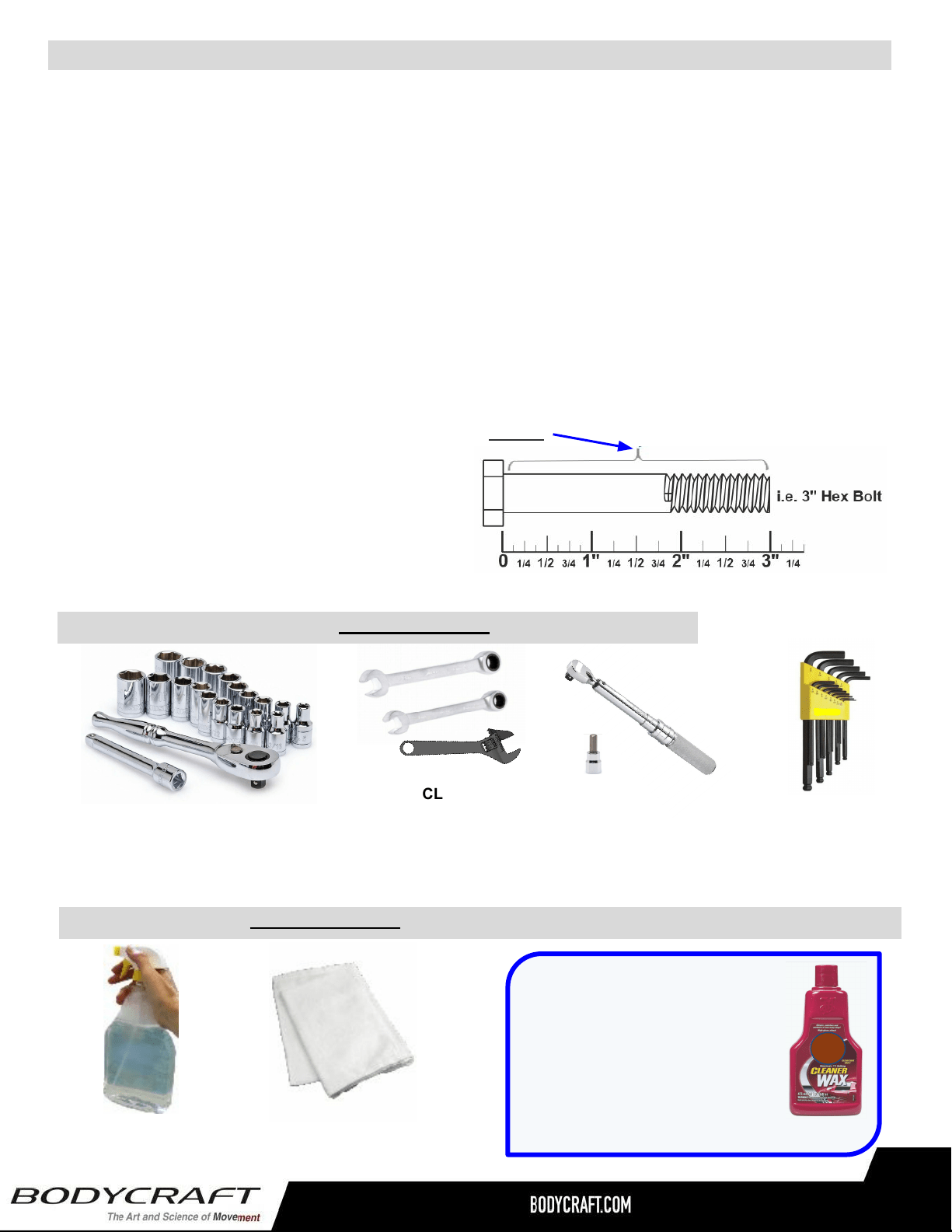
● Keep children away from any BODYCRAFT strength
machines at all times.
● Keep your hands away from cables and pulleys during
operation, other than the designated handles.
● Keep hands, limbs, loose clothing and long hair well out of the way of moving parts.
● Inspect the unit for any sign of wear on parts, hardware becoming loose or cracks on
welds. If a problem is found, do not use or allow the machine to be used until the defective
part is repaired or replaced.
● It is imperative that you retain these Assembly Instructions and be sure all warning labels
are legible and intact. Replacement Assembly Instructions and labels are available from
BODYCRAFT. If you are unsure about the proper use of the BODYCRAFT strength
machine call your local BODYCRAFT dealer or our Customer Service Department.
Contact BODYCRAFT at 800-990-5556 or support@bodycraft.com
Product Safety - Benches & Racks
4
Important Notes and Tips:
1. Before assembly, read all instructions thoroughly and preview diagrams to help make the
installation easier.
2. Make sure all parts are accounted for and in proper condition before beginning assembly.
See the parts list.
3. Be cautious not to damage the flooring when assembling. Place a protectant down such as a
rubber mat or shipping blanket.
4. Let plastics and weight stacks acclimate to room temperature before you begin assembly.
5. Two people are recommended for the safe assembly of this equipment.
6. Insert all bolts in the same direction when possible. Do not tighten until instructed.
7. Carefully install plastic caps using a rubber mallet.
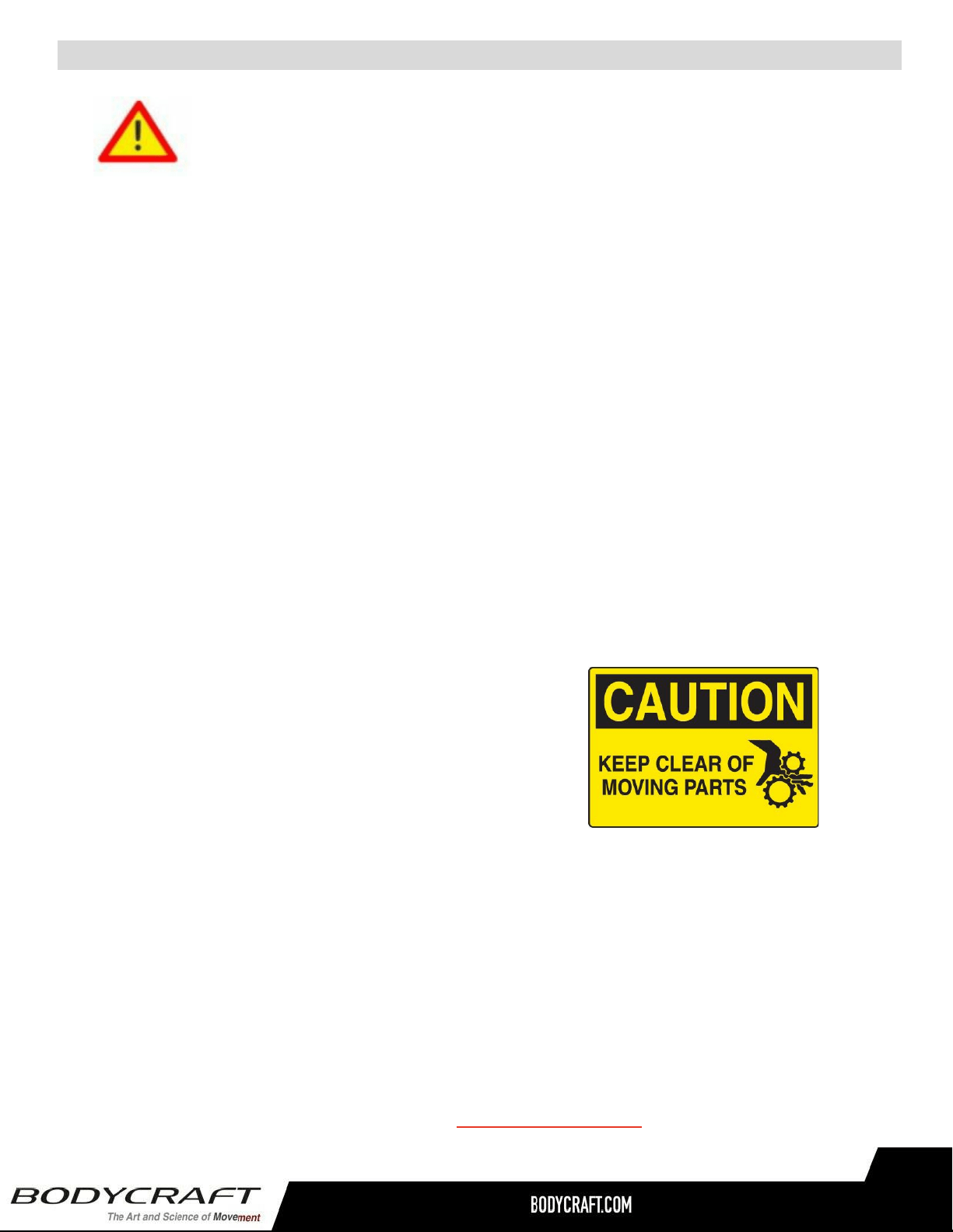
8. When measuring bolt lengths, only measure the shank.
9. When the installation is complete, be sure to
regularly check for rust or damage, and
perform preventative maintenance.
Important Notes, Recommended Tools & Cleaners
TIP ON FRAME ONLY: For extra
protection from fingerprints,
sweat stains or just plain dirt,
apply an automotive grade
cleaner wax if desired. Also
makes future cleaning easier.
THE FOLLOWING IS RECOMMENDED FOR CLEANING:
100% COTTON
CLEANING CLOTHS
(Do Not Use on the Upholstery)
MILD CLEANING
SOLUTION
5
SOCKET SET 3/8 DRIVE & 6” EXT
(Only 1/2, 9/16 & 3/4 Sockets
are needed)
OPEN, CLOSED &
ADJUSTABLE WRENCHES
(Only 1/2, 9/16 & 3/4
are needed)
TORQUE WRENCH
3/8 DRIVE
(w/ 7/32 Allen
Hex Bit Socket)
THE FOLLOWING TOOLS ARE RECOMMENDED FOR ASSEMBLY:
ALLEN WRENCH SET
(Only 7/32 is needed)
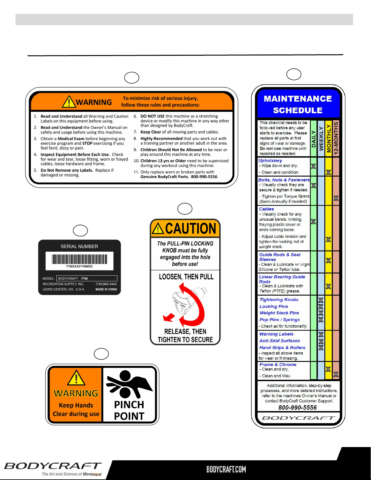
Warning Labels, Maintenance Schedule & Serial Number - F760
6
Carefully read ALL warning, caution & maintenance schedule labels
81
79
80
83
82
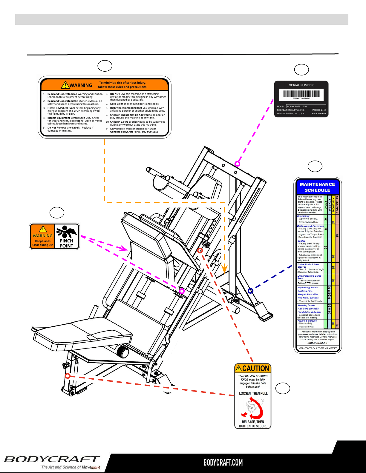
Warning Labels, Maintenance Schedule & Serial Number Placement - F760
7
Carefully read ALL Warning, Caution & Maintenance Schedule labels
Both Rt
& Lt Sides
82
79
83
81
80
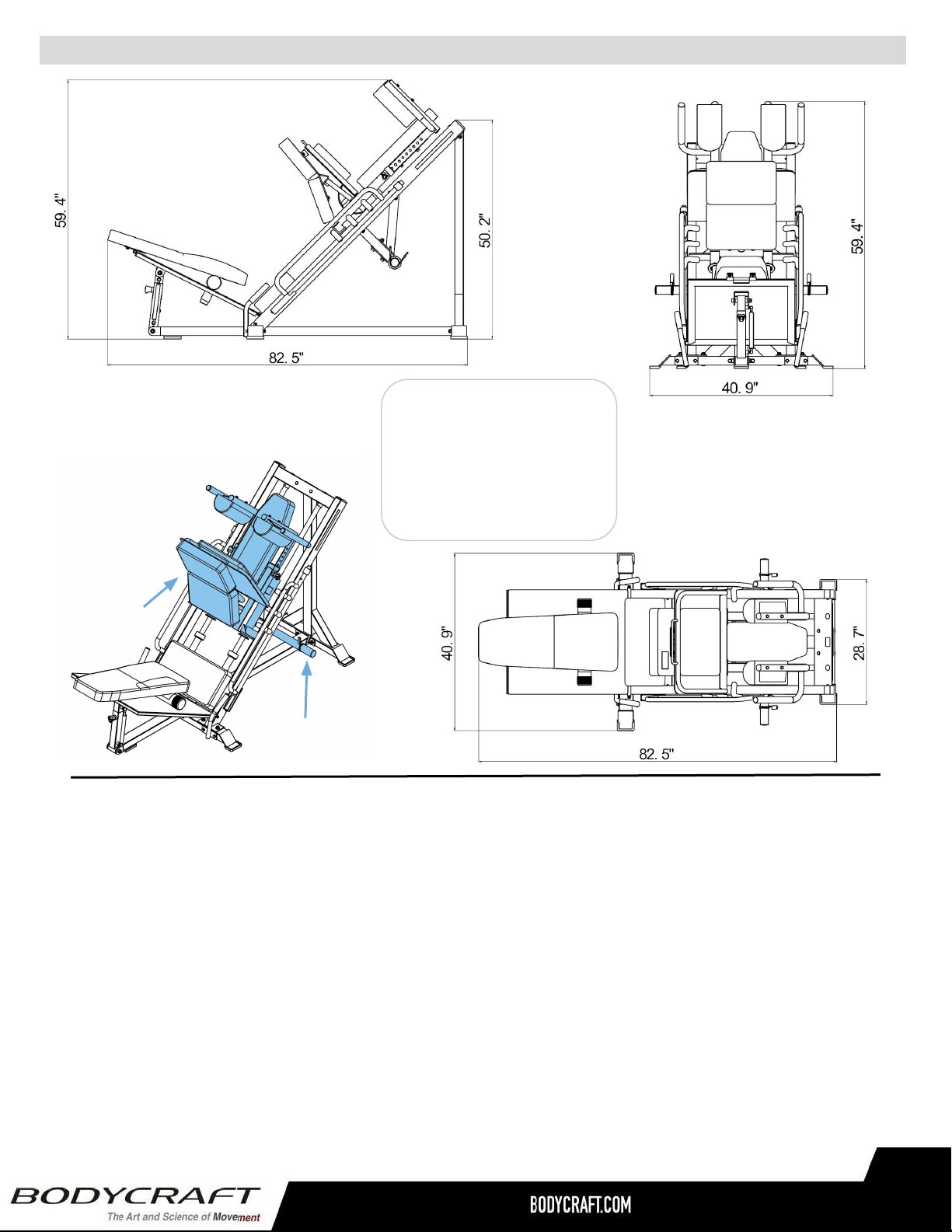
Machine & Shipping Dimensions - F760
8
F760
Overall Dimensions
40.9” W x 82.5” D x 50.2” H
Weight Capacity: 1,000 lbs.
Starting Weight: 80 lbs.
Box # 1: 68-3/4" W x 30-1/2“ D x 9” H (1,750mm W x 775mm D x 227mm H)
Shipping Weight Gross Weight: 180.4 lbs (82 kg)
Net Weight: 171.6 lbs (78 kg)
Box # 2: 49-1/2" W x 30-1/2" D x 5-1/2" H (1,260mm W x 775mm D x 142mm H)
Shipping Weight Gross Weight: 110.0 lbs (50 kg)
Net Weight: 101.2 lbs (46 kg)
Box # 3: 42-1/2" W x 28-3/4" D x 10-1/2" H (1,080mm W x 730mm D x 267mm H)
Shipping Weight Gross Weight: 145.2 lbs (66 kg)
Net Weight: 136.4 lbs (62 kg)
Front View
Side View
Top View
Starting Weight:
80 lbs (36 kg)
Weight Capacity:
1,000 lbs (454 kg)
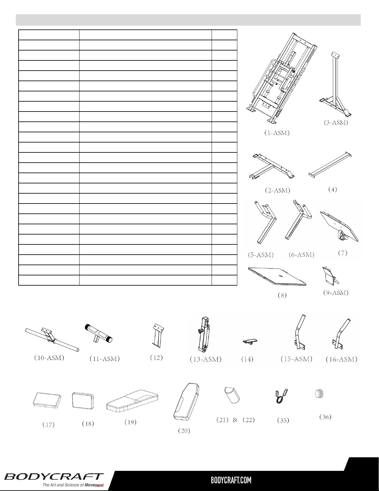
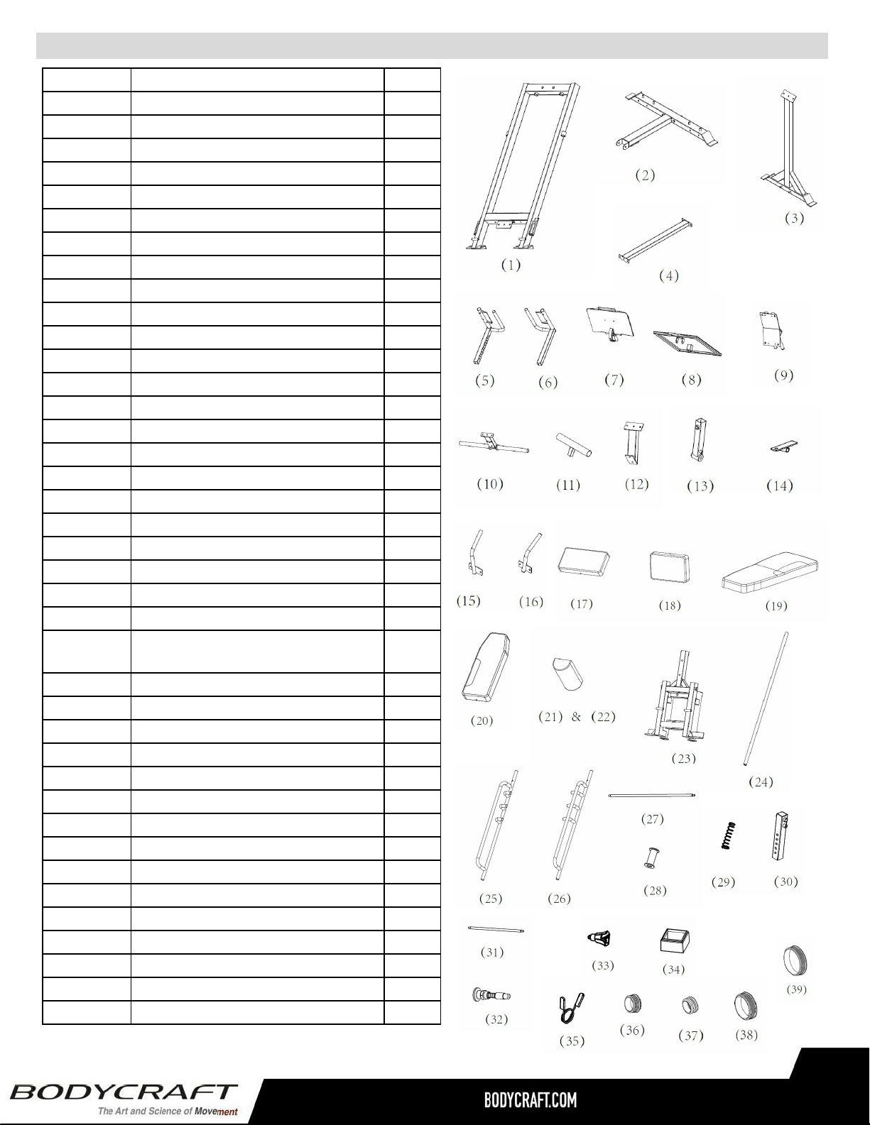
Assembly Parts - F760 1 of 2
9
NOTE: Parts are not to scale
Part # Assembly Parts List QTY
F760-001-ASM Frame, Main - Assembly 1
F760-002-ASM Frame, Front, Stabilizer - Assembly 1
F760-003-ASM Frame, Rear, Upright - Assembly 1
F760-004 Frame, Bottom, Connector 1
F760-005-ASM Frame, Right Shoulder, Adjusting - Assembly 1
F760-006-ASM Frame, Left Shoulder, Adjusting - Assembly 1
F760-007 Plate, Leg Press 1
F760-008 Foot Platform 1
F760-009-ASM Plate, Back Pad - Assembly 1
F760-010-ASM Weight Plate Holder - Assembly 1
F760-011-ASM Foot Tube - Assembly 1
F760-012 Weight Holder Support 1
F760-013-ASM Foot Platform Adjuster Sleeve - Assembly 1
F760-014 Hinge, for Foot Platform 2
F760-015-ASM Handle, Right - Assembly 1
F760-016-ASM Handle, Left - Assembly 1
F760-017 Pad, Seat 1
F760-018 Pad, Back and Hip 3
F760-019 Pad, Back, Lower 1
F760-020 Pad, Back, Upper 1
F760-021 Pad, Shoulder, Right 1
F760-022 Pad, Shoulder, Left 1
F760-035 Spring Clip 2
F760-036 Plug, Round φ25 2
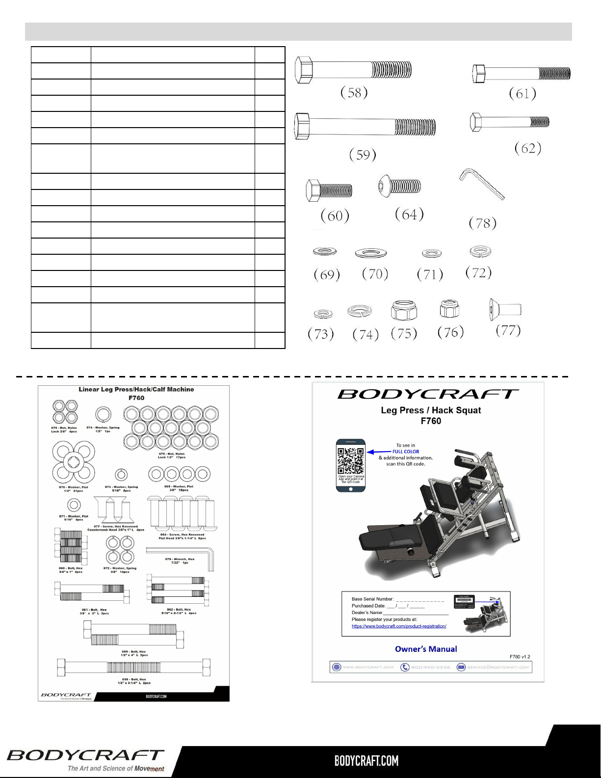
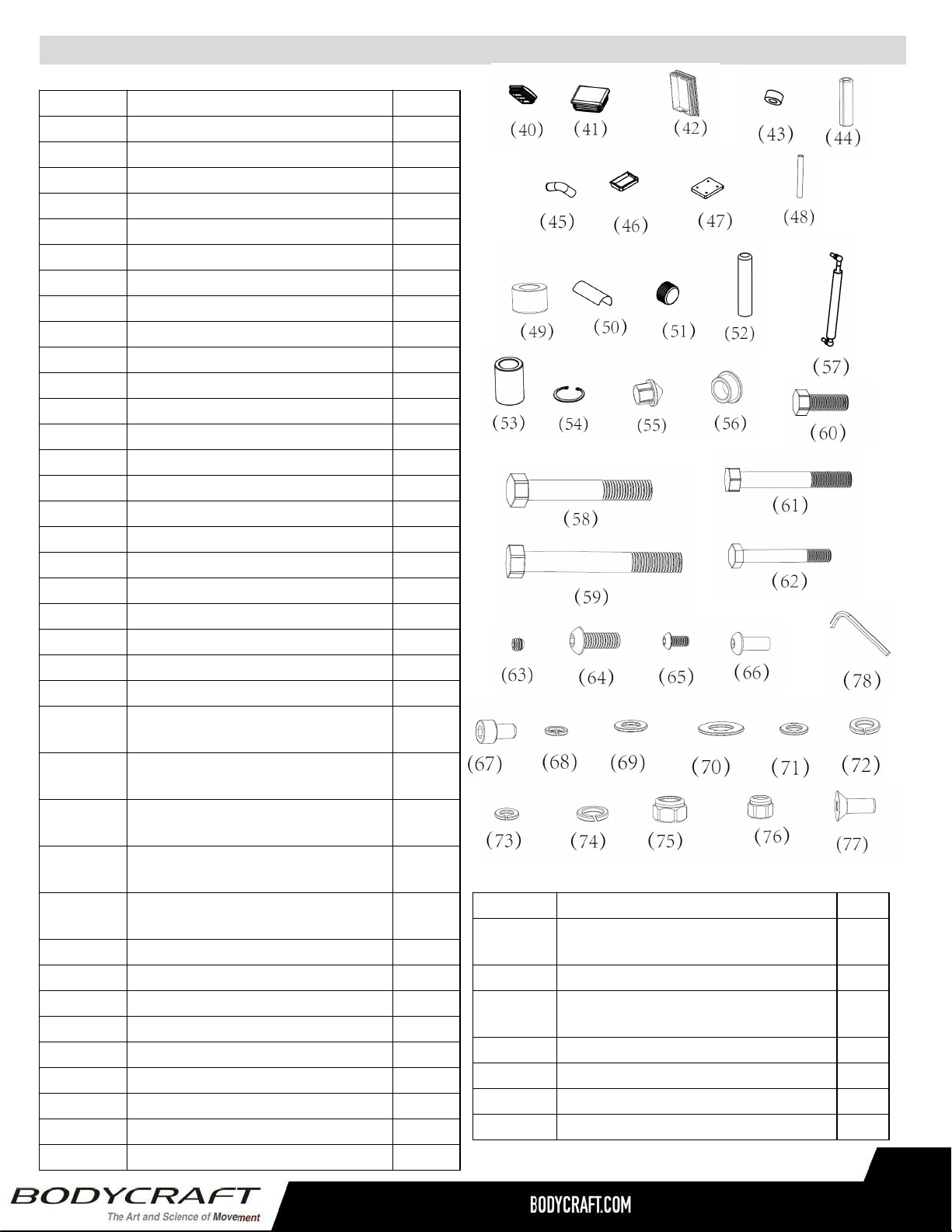
Assembly Parts - Hardware - F760 2 of 2
10
Hardware Kit
Inside Box #2
Owner’s Manual
Inside Box #2
NOTE: Parts are not to scale
Part # Assembly Hardware QTY
F760-058 Bolt, Hex 1/2″ x 3-1/4″ L - BLACK 2
F760-059 Bolt, Hex 1/2″ x 4″ L - BLACK 2
F760-060 Bolt, Hex 3/8″ x 1″ L - BLACK 4
F760-061 Bolt, Hex 3/8″ x 3″ L - BLACK 2
F760-062 Bolt, Hex 5/16″ x 2-1/2″ L - BLACK 4
F760-064
Bolt, Hex Button Head 3/8″ x 1- 1/4″
L- BLK 8
F760-069 Washer, Flat 3/8″ - BLACK 18
F760-070 Washer, Flat 1/2″ - BLACK 21
F760-071 Washer, Flat 5/16″ - BLACK 7
F760-072 Washer, Spring 3/8" - BLACK 14
F760-073 Washer, Spring 5/16" - BLACK 4
F760-074 Washer, Spring 1/2" - BLACK 1
F760-075 Nut, Nylon Lock 1/2″ - BLACK 17
F760-076 Nut, Nylon Lock 3/8″ - BLACK 4
F760-077
Bolt, Hex Recessed Countersunk
Head 3/8″ x 1" L- BLK 4
F760-078 Wrench, Hex 7/32" 1
Product Assembly - Preassembly Tips - F760
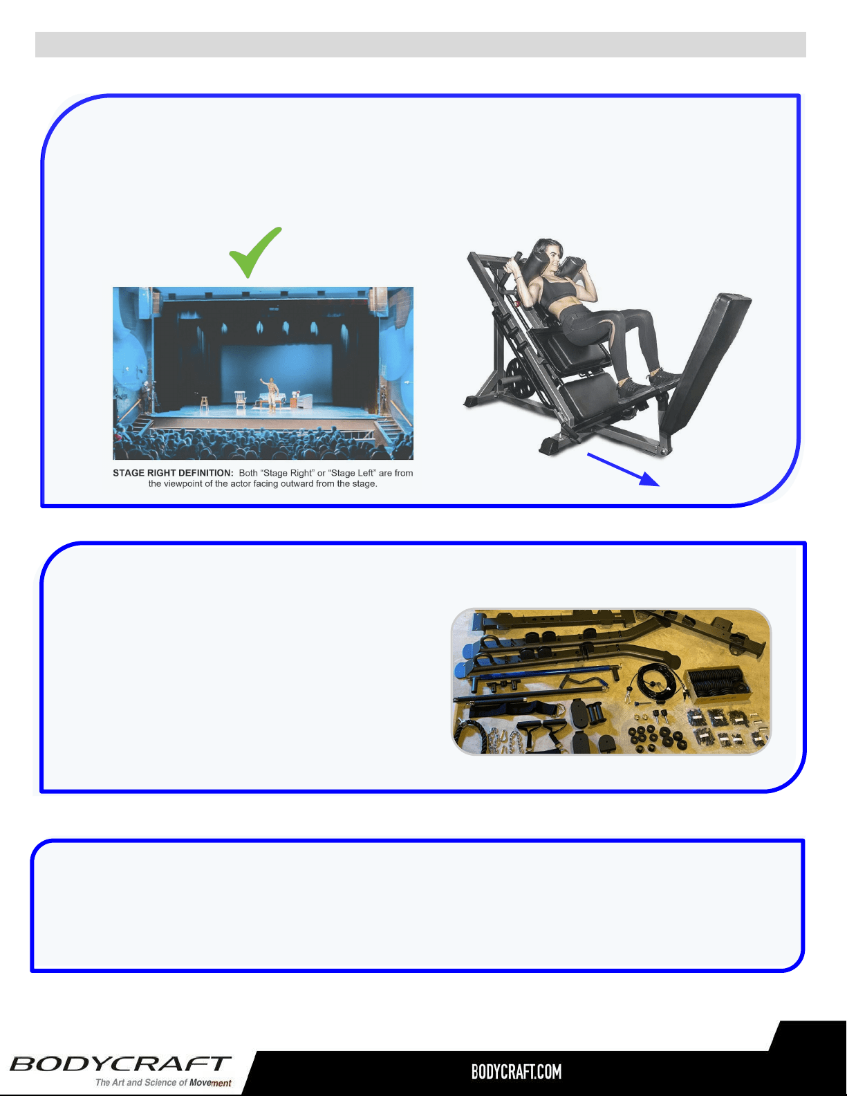
PREASSEMBLY TIP #1 – “Stage Right”.
During the assembly process we will be stating Right, Left, Front, Back, Top, or Bottom. These
all are in the perspective of the user in the machine facing outward with feet facing the ground.
See below images as examples.
PREASSEMBLY TIP #2 – Unpackaging & organizing.
PREASSEMBLY TIP #3 – Keep hardware loose until asked to tighten.
During the assembly, hardware needs to be finger tight until the STEPS of “Torque Time”. This will
ensure sub-frame and other parts will easily fit together and not strip out bolt threads during assembly.
11
The best practice in assembly is to take all the
parts out of the boxes & bags and line up in order
of assembly. This enables a mindset of what you
will be assembling, their physical sizes and what
challenges you might face BEFORE you begin.
Right Side
Back
Front
Left Side
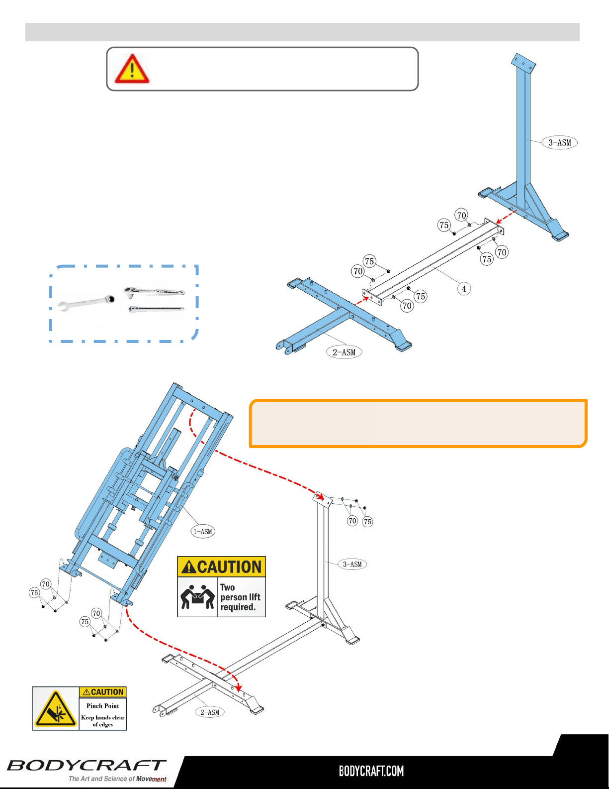
Product Assembly - F760 - STEP 1a, 1b
12
3/4 SOCKET &
6” EXTENSION
Recommended Tools
3/4 WRENCH
STEP 1a: Installation of the Base Frames
Attach the Frame, Bottom, Connector (4) to the Frame, Front
Stabilizer -Assembly (2-ASM) and the Frame, Rear, Upright -
Assembly (3-ASM) using:
● Four WASHERS, Flat 1/2" (70)
● Four NUTS, Nylon Lock 1/2" (75)
Please Hand Tighten All Bolts Until STEP 1d
STEP 1b: Installation of the
Main Frame Assembly (172 lbs)
Attach the Frame, Main-
Assembly (1-ASM) to the Frame,
Front Stabilizer -Assembly
(2-ASM) and the Frame, Rear,
Upright - Assembly (3-ASM) using:
● Six WASHERS, Flat
1/2" (70)
● Six NUTS, Nylon
Lock 1/2" (75)
CAUTION: Main Frame Assembly (1-ASM) weighs 172 lbs.
Minimum two person lift during STEP 1b.
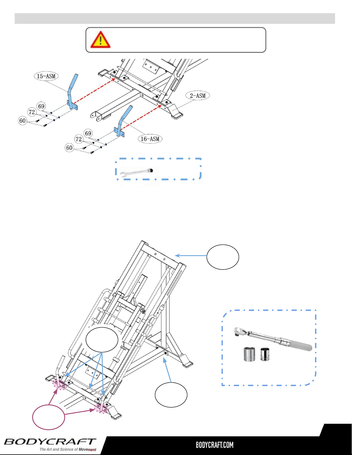
Product Assembly - F760 - STEP 1c, 1d
13
Please Hand Tighten All Bolts Until STEP 1d
STEP 1d: “Torque Time”
● Tighten all 1/2” locking nuts to the frame welded-on bolts, starting at the bottom and working
your way up, to the recommended torque specs of 20 ft-lbs (+/- 2 lbs)
● All 4 bolts (#60) go directly into a tapped frame, to the torque specs of 17 ft-lbs (+/- 2 lbs).
TORQUE WRENCH
w/ 9/16 & 3/4 SOCKETS
Recommended Tools:
20 ft-lbs
(+/- 2 lbs)
20 ft-lbs
(+/- 2 lbs)
20 ft-lbs
(+/- 2 lbs)
17 ft-lbs
(+/- 2 lbs)
STEP 1c: Installation of the
Handle Assemblies
Attach the Handle, Right -
Assembly (15-ASM) & the Handle,
Left Assembly (16-ASM) to the
Frame, Front, Stabilizer - Assembly
(2-ASM) using:
● Four BOLTS, Hex 3/8" x 1” (60)
● Four WASHERS, Spring 3/8" (72)
● Four WASHERS, Flat 3/8" (69)
Recommended Tool
9/16 WRENCH
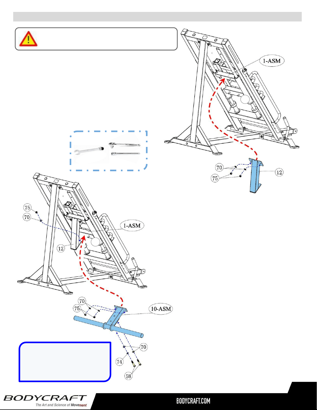
Product Assembly - F760 - STEP 2a, 2b
14
Please Hand Tighten All Bolts Until STEP 3c
STEP 2b: Installation of the Weight Holder
Attach the Weight Plate Holder - Assembly
(10-ASM) to the Frame, Main Assembly (1-ASM)
on the bottom side, lower cross frame, Moving
Carriage (23) & the Weight Holder Support (12)
using:
● Two WASHERS, Flat 1/2" (70)
● Two NUTS, Nylon Lock 1/2" (75)
3/4 SOCKET &
6” EXTENSION
Recommended Tools
3/4 WRENCH
STEP 2a: Installation of the Weight Horn Support
Attach the Weight Holder Support (12) to the Frame,
Main Assembly (1-ASM) on the bottom side, upper cross
frame, Moving Carriage (23) using:
To the Main Frame Assembly (1-ASM)
● Two WASHERS, Flat 1/2" (70)
● Two NUTS, Nylon Lock 1/2" (75)
To the Weight Holder Support (12)
● Two BOLTS, Hex 1/2“ x 3-1/4“ (58)
● Three WASHERS, Flat 1/2" (70)
● One WASHER, Spring 1/2" (74)
● One NUT, Nylon Lock 1/2" (75)
NOTE: Bottom Bolt #58 uses
the Spring Washer and the
Flat Washer when NOT using
the Nylon Locking Nut.
23
23
Product Assembly - F760 - STEP 3a, 3c
15
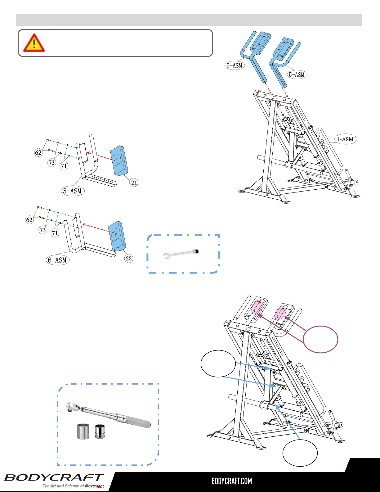
STEP 3a: Installation of the Shoulder Assemblies
Attach the Pad, Shoulder, Right & Left (21, 22) to the
Frame, Right Shoulder, Adjusting - Assembly (5-ASM) and
the Frame, Left Shoulder, Adjusting - Assembly (6-ASM)
using:
STEP 3c: “Torque Time”
● Tighten the Weight Horn Support & Holder 1/2”
Bolts & Locking Nuts, starting at the bottom and
working your way up, to the recommended
torque specs of 20 ft-lbs (+/- 2 lbs)
● All 4 bolts (#62) go directly into the pads, to
the torque specs of 8 ft-lbs (+/- 1 lbs).
Please Hand Tighten All Bolts Until STEP 3c
● Four BOLTS, Hex
5/16" x 2-1/2” (62)
● Four WASHERS,
Spring 5/16" (73)
● Four WASHERS,
Flat 5/16"" (71)
STEP 3b: Install both Shoulder
Assemblies on the the Main Frame
Assembly
Loosen the Pull-Pin locking knobs to
slip down, then tighten Pull-Pins.
Recommended Tool
1/2 WRENCH
8 ft-lbs
(+/- 1 lbs)
20 ft-lbs
(+/- 2 lbs)
20 ft-lbs
(+/- 2 lbs)
TORQUE WRENCH
w/ 1/2 & 3/4 SOCKETS
Recommended Tools:
Product Assembly - F760 - STEP 4a, 4b
16
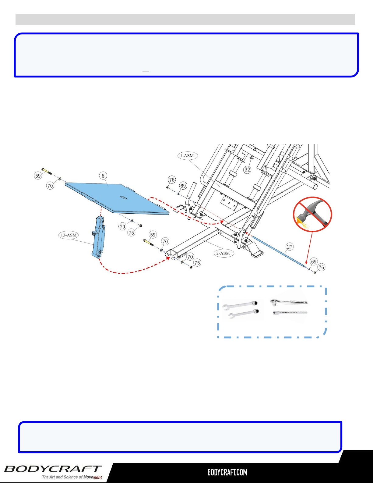
STEP 4a: Installation of the Foot Platform
Attach the Foot Platform (8) to the Frame, Main - Assembly (1-ASM) with the Axle, Long (27), then
push forward. Continue with the installation of the Foot Platform Adjuster Sleeve - Assembly
(13-ASM) to the Frame, Front, Stabilizer - Assembly (2-ASM). Finish by connection the Foot Platform
Adjuster Sleeve - Assembly upper part to the base of the Foot Platform. Use the following hardware:
NOTE: The Long Axle (27) & Short Axle (31) are pre-assembled in the Main Frame Assembly (1-ASM).
Take both out to start STEP 4a and STEP 4c by using a 9/16 wrench or socket on the Nuts (76).
** Gently tap out the Axle with the Nut or with block of wood on the end, so not to damage the treads. **
First: Foot Platform to the Main Frame Assembly
● Two WASHERS, Flat 3/8" (69)
● Two NUTS, Nylon Lock 3/8"(76)
Second: Adapter Sleeve to Front Frame &
Foot Platform
● Two BOLTS, Hex 1/2“ x 4” (59)
● Four WASHERS, Flat 1/2" (70)
● Two NUTS, Nylon Lock 1/2" (75)
9/16 & 3/4 SOCKETS w/
6” EXTENSION
Recommended Tools
9/16 & 3/4
WRENCHES
STEP 4b: “Torque Time”
● Nuts, Nylon Lock 3/8” (76) to
15 ft-lbs +/- 2 lb.
● BOLTS, Hex Head 1/2“ (59) to
20 ft-lbs +/- 2 lbs.
NOTE: Once tightened, test the Foot Platform (8) travel. It should move easily. If you find that it is
not, slightly loosen the 1/2" x 4" BOLTS (59), and recheck.
Product Assembly - F760 - STEP 4c, 4d
17
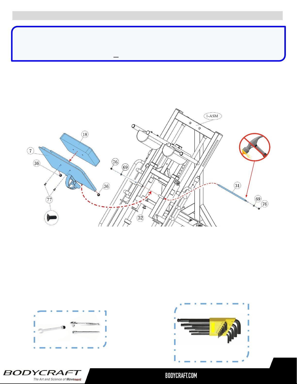
STEP 4c: Installation of the Leg Press Assembly
Attach the Plate, Leg Press (7) to the Frame, Main - Assembly (1-ASM) with the Axle, Short (31), then
lock in with the Pull-Pin #1 (32). Continue with installation of the Pad, Back (18) to the Plate, Leg Press
Assembly (7-ASM). Finish with the Plug, Round 25mm (36) on the right & left bottom sides on the Plate,
Leg Press Assembly. Use the following hardware:
ALLEN WRENCH
7/32
Recommended Tool
Second: Back Pad to the Leg Press Assembly
● Two BOLTS, Hex Recessed Countersunk
Head 3/8″ x 1" (77)
STEP 4d: “Torque Time”
● Nuts, Nylon Lock 3/8” (76) to
15 ft-lbs +/- 2 lb.
● BOLTS, Hex Countersunk Head
3/8” (64) to 8 ft-lbs +/- 1 lbs.
First: Leg Press to the Main Frame Assembly
● Two WASHERS, Flat 3/8" (69)
● Two NUTS, Nylon Lock 3/8" (76)
9/16 SOCKET &
6” EXTENSION
Recommended Tools
9/16 WRENCH
NOTE: The Long Axle (27) & Short Axle (31) are pre-assembled in the Main Frame Assembly (1-ASM).
Take both out to start STEP 4a and STEP 4c by using a 9/16 wrench or socket on the Nuts (76).
** Gently tap out the Axle with the Nut or with block of wood on the end, so not to damage the treads. **
Product Assembly - F760 - STEP 5a, 5b
18
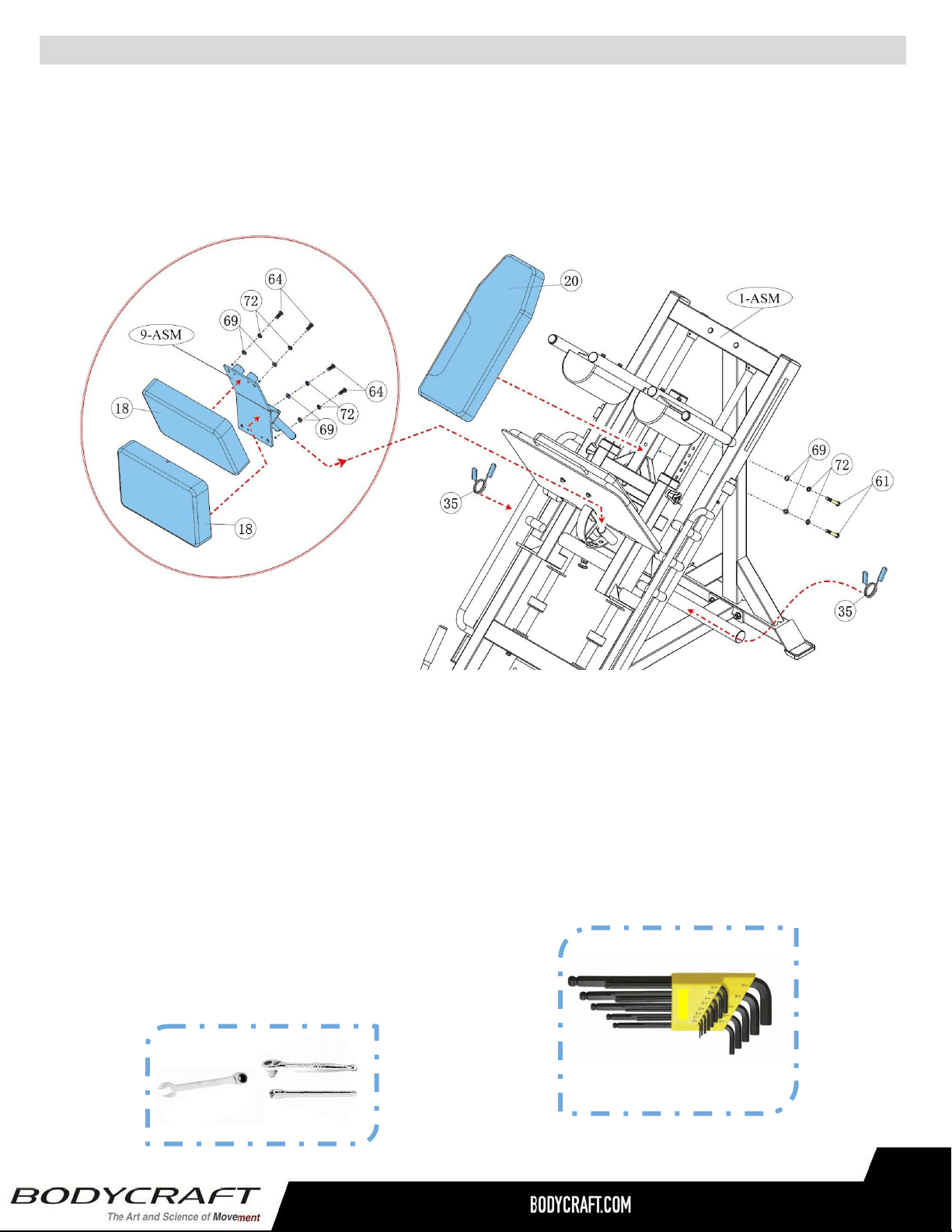
Second: Back Pads to the Back Plate
● Four BOLTS, Hex 3/8" x 1-1/4” (64)
● Four WASHERS, Spring 3/8" (72)
● Four WASHERS, Flat 3/8" (69)
STEP 5b: “Torque Time”
● BOLTS, Hex & Button Head 3/8”
(61, 64) to 8 ft-lbs +/- 1 lbs.
First: Upper Back Pad to the Main Frame
Assembly
● Two BOLTS, Hex 3/8" x 3” (61)
● Two WASHERS, Spring 3/8" (72)
● Two WASHERS, Flat 3/8" (69)
9/16 SOCKET &
6” EXTENSION
Recommended Tools
9/16 WRENCH
STEP 5a: Installation of the Back Pads
Attach the Pad, Back, Upper (20) to the Frame, Main - Assembly (1-ASM). Continue with installation
of the Pads, Back (18) to the Plate, Back Pad - Assembly (9-ASM), then insert into the Plate, Leg
Press - Assembly (7-ASM), see image below.. Finish with the Spring Clips (35) on the right & left
bottom sides on the Weight Plate Holder - Assembly (10-ASM) . Use the following hardware:
ALLEN WRENCH
7/32
Recommended Tool
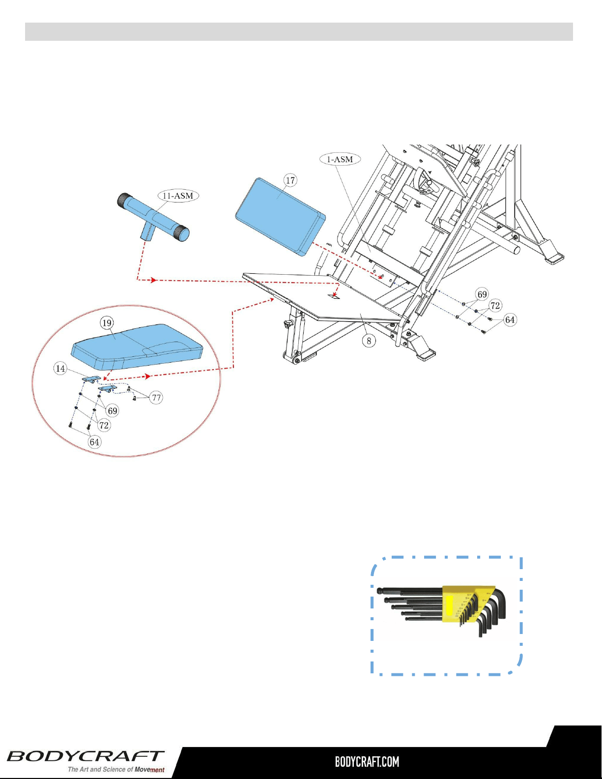
Product Assembly - F760 - STEP 5c, 5d
19
STEP 5c: Installation of the Seat & Lower Back Pads
Attach the Pad, Seat (17) to the Frame, Main - Assembly (1-ASM). Continue with installation with the
Pad, Back, Lower (19) to the Foot Platform (8). Finish with the Foot Tube - Assembly (11-ASM) on the
Foot Platform. Use the following hardware:
Second: Back Pad to the Foot Plate
● Two BOLTS, Hex 3/8" x 1-1/4” (64)
● Two WASHERS, Spring 3/8" (72)
● Two WASHERS, Flat 3/8" (69)
● Two BOLTS, Hex Recessed
countersunk Head 3/8" x 1” (77)
STEP 5d: “Torque Time”
● BOLTS, Hex & Button Head 3/8”
(61, 64, 77) to 8 ft-lbs +/- 1 lbs.
First: Seat Pad to the Main Frame Assembly
● Two BOLTS, Hex 3/8" x 1-1/4” (64)
● Two WASHERS, Spring 3/8" (72)
● Two WASHERS, Flat 3/8" (69)
ALLEN WRENCH
7/32
Recommended Tool
Product Assembly - F760 - STEP 6
STEP 6c:
Double check at this time:
● All Bolts, Nuts and Pop-Pins are
tightened
● All Safety Arms and Bar Catches
move smoothly
● All Pop-Pins fully engage into the
Upright holes
● Machine is fully operational.
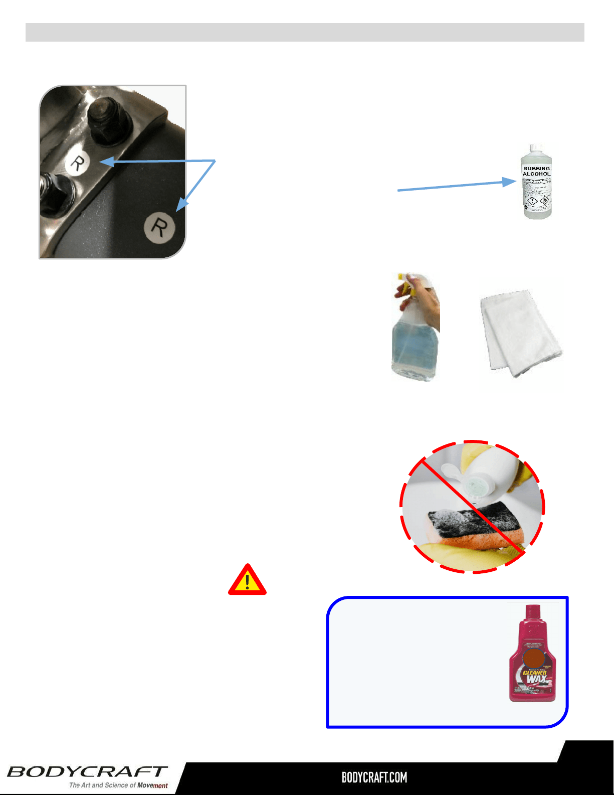
STEP 6a - 6c: Final Assembly Clean Up, Polish and Double Checks
STEP 6a: Remove all assembly stickers, i.e. part numbers &
right left circles.
● Easy to remove with fingernail or plastic scraper
● If adhesive residue is on frame:
○ Use rubbing alcohol
○ Then mild cleaning solution
○ Finishing with a dry 100% cotton cleaning cloth
100% COTTON
CLEANING CLOTHS
MILD CLEANING
SOLUTION
TIP ON FRAME ONLY: For extra
protection from fingerprints,
sweat stains or just plain dirt,
apply an automotive grade
cleaner wax if desired. Also
makes future cleaning easier.
(Do Not Use on the Upholstery)
STEP 6b: Frame clean up.
● Wipe down frame with mild cleaning solution
● Dry frame with 100% cotton cleaning cloth
● Good practice to do before first use and yearly:
○ Lightly apply an automotive grade cleaner wax
○ Then follow up by wiping excesses off with 100%
cotton cleaning cloth
● DO NOT USE ABRASIVE CLEANING SCRUBBING PADS
● DO NOT USE AMMONIA OR CITRIC CLEANERS
● DO NOT USE ANY FORM OF PAINT THINNERS
20
NOTE: Parts are not to scale
21
Detailed Parts List - F760 1 of 2
Part # Detailed Parts list QTY
F760-001 Frame, Main 1
F760-002 Frame, Front, Stabilizer 1
F760-003 Frame, Rear, Upright 1
F760-004 Frame, Bottom, Connector 1
F760-005 Frame, Right Shoulder, Adjusting 1
F760-006 Frame, Left Shoulder, Adjusting 1
F760-007 Plate, Leg Press 1
F760-008 Foot Platform 1
F760-009 Plate, Back Pad 1
F760-010 Weight Plate Holder 1
F760-011 Foot Tube 1
F760-012 Weight Holder Support 1
F760-013 Foot Platform Adjuster Sleeve 1
F760-014 Hinge, for Foot Platform 2
F760-015 Handle, Right 1
F760-016 Handle, Left 1
F760-017 Pad, Seat 1
F760-018 Pad, Back and Hip 3
F760-019 Pad, Back, Lower 1
F760-020 Pad, Back, Upper 1
F760-021 Pad, Shoulder, Right 1
F760-022 Pad, Shoulder, Left 1
F760-023 Frame, Moving Carriage 1
F760-024
Solid Linear Bearing Rod, 30mm OD x
1,400mm L 2
F760-025 Stopper, Safety, Right 1
F760-026 Stopper, Safety, Left 1
F760-027 Axle, Long 1
F760-028 Support Tube 2
F760-029 Spring 2
F760-030 Foot Platform Adjuster Inside Tube 1
F760-031 Axle, Short 1
F760-032 Pull Pin 1 1
F760-033 Pull Pin 2 3
F760-034 Plastic Sleeve 2
F760-035 Spring Clip 2
F760-036 Plug, Round φ25 4
F760-037 Plug, Round Φ32 2
F760-038 Plug, Round φ38 4
F760-039 Plug, Round φ48 2
NOTE: Parts are not to scale
22
Detailed Parts List - F760 2 of 2
F760-040 Plug, Rectangular 75mm x 50mm 2
F760-041 Plug, Square 50mm x 50mm 1
F760-042 Plug, Square 45mm x 45mm 1
F760-043 Rubber Cushion 2
F760-044 Locking Pin 2
F760-045 Plastic Cap 6
F760-046 Foot Pad 1 4
F760-047 Foot Pad 2 1
F760-048 Foam 2
F760-049 Crash Cap 3
F760-050 Non-slip Mat 2
F760-051 Cap, Round End 2
F760-052 Hand Grip 2
F760-053 Linear Bearing 4
F760-054 Circlip 4
F760-055 Cap, End, Pointed 2
F760-056 Bushing 4
F760-057 Compressed Spring 1
F760-058 Bolt, Hex 1/2″ x 3-1/4″ L - BLACK 2
F760-059 Bolt, Hex 1/2″ x 4″ L - BLACK 2
F760-060 Bolt, Hex 3/8″ x 1″ L - BLACK 6
F760-061 Bolt, Hex 3/8″ x 3″ L - BLACK 2
F760-062 Bolt, Hex 5/16″ x 2-1/2″ L - BLACK 4
F760-063
Screw, Inner Hex Set 5/16″ x 1/4″ L-
BLK 2
F760-064
Bolt, Hex Button Head 3/8″ x 1- 1/4″
L- BLK 8
F760-065
Bolt, Hex Button Head M6 x 12mm L-
BLK 4
F760-066
Bolt, Hex Button Head 5/16″ x 3/4″ L-
BLK 3
F760-067
Bolt, Hex Socket Cap 5/16″ x 1/2″ L-
BLK 1
F760-068 Washer, Spring φ8 - BLACK 2
F760-069 Washer, Flat 3/8″ - BLACK 20
F760-070 Washer, Flat 1/2″ - BLACK 21
F760-071 Washer, Flat 5/16″ - BLACK 7
F760-072 Washer, Spring 3/8" - BLACK 16
F760-073 Washer, Spring 5/16" - BLACK 4
F760-074 Washer, Spring 1/2" - BLACK 1
F760-075 Nut, Nylon Lock 1/2″ - BLACK 17
F760-076 Nut, Nylon Lock 3/8″ - BLACK 4
Part # Detailed Parts list QTY
Part # Detailed Parts list QTY
F760-077
Bolt, Hex Recessed Countersunk Head
3/8″ x 1" L- BLK 4
F760-078 Wrench, Hex 7/32" 1
F760-079
Warning Label - Master Rules and
Precautions 1
F760-080 Warning Label - Pinch Point, Horizontal 2
F760-081 Warning Label - Pull-Pin Locking Knob 3
F760-082 Label - Maintenance Schedule 1
F760-083 Label - Serial Number 1
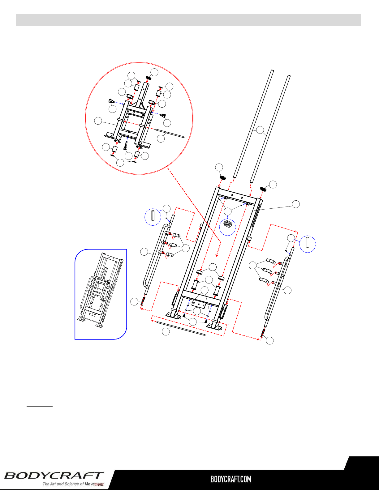
Detailed Parts - Exploded View - Main Frame Assembly (001-ASM) - F760 1 of 2
23
View Keys
Red dotted (large): Structural parts assembled direction.
Red dotted (med): Sub-parts assembled direction.
Blue dotted lines (small): Hardware assembled direction.
NOTE: Parts are not to scale
44
25
26
45
28
43
60
72
27
29
29
69
Locking Pin
24
54
54
53
53
53
34
34
33
33
41
31
53
54
32
23
44
63
45
Inner Hex Screw
5/16” x 1/4”
Locking Pin
1
40
40
Assembled View
Main Frame Assembly (001-ASM)
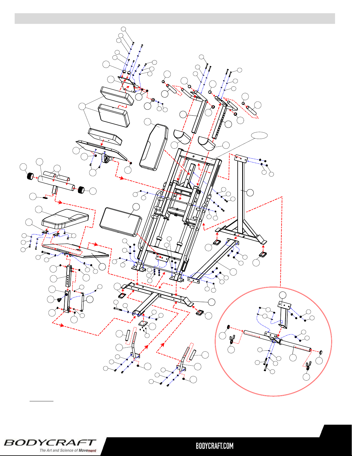
Detailed Parts - Exploded View - F760 2 of 2
24
37
48
49
56
56
2
6
5
9
8
13
18
17
22
30
56
20
3
37
55
38
38
57
46
48
4
14
21
33
19
38
56
49
38
69
46
72
64
69
76
70
75
70
75
69
76
70
75
70
75
70
75
46
62
73
71
62
73
71
69
76
72
69
61
69
76
71
66
69
72
64
69
72
64
11
50
51
51
42
71
66
52
16
36
72
69
60
52
15
36
72
69
60
47
65
75
70
59
70
46
68
68
67
70
75
59
70
7
36
36
77
64
72
69
77
10
35
39
58
12
75
70
70
75
70
70
74
58
35
39
75
70
1-ASM
View Keys
Red dotted (large): Structural parts assembled direction.
Red dotted (med): Sub-parts assembled direction.
Blue dotted lines (small): Hardware assembled direction.
NOTE: Parts are not to scale
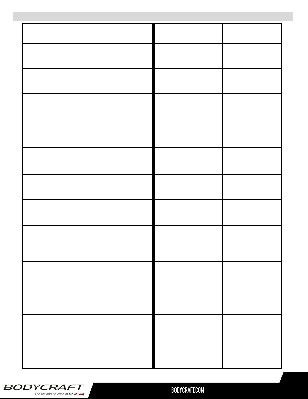
Strength Maintenance & Routine Schedule
25
ROUTINE SCHEDULE
LIGHT
COMMERCIAL
HOME
Clean:
Upholstery.
DAILY
1 - 2 WEEKS
Inspect:
Cables or Belts and their tension.
DAILY 1 - 2 WEEKS
Inspect:
Links, Pull Pins, Snap Locks,
Swivels, and Weight Stack Pins.
DAILY
1 - 2 WEEKS
Inspect:
Accessory Bars and Handles.
WEEKLY
3 - 6 MONTHS
Inspect:
All Label and Weight Stack
Stickers.
WEEKLY
3 - 6 MONTHS
Inspect:
All Nuts and Bolts, tighten if needed.
WEEKLY 3 - 6 MONTHS
Inspect:
Anti-Skid Surface.
WEEKLY
3 - 6 MONTHS
Clean & Lubricate:
Guide Rods with 100% Silicone or
a Teflon based lubricant with
Super Lube (a PTFE grease).
MONTHLY
3 - 6 MONTHS
Lubricate:
Seat Sleeves, Bushings,
Linear Bearing.
MONTHLY
3 - 6 MONTHS
Clean and Wax:
All Glossy Finishes.
6 MONTHS
YEARLY
Repack with Grease:
Linear Bearings.
6 MONTHS
YEARLY
Replace:
Cables, Belts and Connecting Parts
when showing signs of wear.
YEARLY
2 - 4 YEARS

Strength Maintenance - Lubrication
26
LUBRICATION MAINTENANCE
Lubrication
Bearing and linear bearing systems have advanced over the years, but they must be
maintained on a regular basis if you expect them to last and perform efficiently. BODYCRAFT
uses only the highest quality bearings and linear motion components that are virtually
trouble-free but they require the regular preventive maintenance to ensure long- lasting
performance.
1. Bronze bushings: Recommend on a yearly basis to spray a Teflon-base lubricant
(silicone-free) directly onto the shaft as it passes through these bushings. Spray a
small amount onto the shaft and rotate it through its complete movement and wipe
off any excess.
2. Weight stack guide rods: Use Silicone Spray lubricant and this time spray onto a
rag and wipe the guide rods down with this rag on a weekly basis. DO NOT use
WD-40 or other lubricants as they attract dirt and will create a mess between the
weight plates and bushings.
3. Sealed bearings pivot points: As the name implies, they are protected from the
outside environment and require no lubrication. During the machine wipe down, wipe
the external bearing surfaces with the damp rag and dry to prevent the build up of
dust and sweat.
4. Linear bearing systems (if equipped): These are precision, high load components
that require regular maintenance. Dirt and corrosion are the major culprits in linear
bearing failure. The hardened shafts must be wiped down monthly and lubricated
with a light layer of Teflon grease. We recommend a Teflon-based (silicone-free)
gel/grease for this purpose. Lack of care and maintenance will result in corrosion of
the linear shaft causing the bearings to become clogged and jammed.
If you perform the maintenance procedures, you will increase the life of the machine and
ultimately lower your maintenance costs with fewer replaced components and downtime.

Service Request
27
Required Information BEFORE Initiating
a Service Case
The following information is needed to help expedite troubleshooting and to
ensure the correct part(s) are sent if needed for a repair:
1) What product / model # do you have?
2) Unit serial number?
3) Installed by a dealer or direct sale?
4) Date of installation?
5) Date of service issue?
6) Complaint or problem, including any Error Codes?
7) Has the software been updated?
8) What part(s) are being requested?
9) Any picture or video will help with troubleshooting or exact part(s) needed.
Residential Warranty for Strength Equipment:
Frame: Lifetime, Parts: Lifetime
Commercial Warranty for Strength Equipment:
Frame: 10 years, Parts: 2 years
This warranty excludes the following:
1. The warranty does not cover normal maintenance or labor charges unless labor terms are listed
above.
2. Normal cosmetic wear on parts such as paint, seat coverings, foot rails, labels and logos.
3. Any accessories not included in the original packaging.
4. Warranty does not cover normal wear and tear.
* This warranty is in lieu of all warranties, expressed or implied, and/or all other obligations or liabilities on our
part, and we neither assume nor authorize any person to assume for us any other obligation or liability in
connection with the sale of your BODYCRAFT product. Under no circumstances shall we be liable by virtue of
this warranty or otherwise for damage to any person or property whatsoever for any special, indirect,
incidental, secondary or consequential damage of any nature whatsoever arising out of the use or inability to
use the BODYCRAFT product.
Register your product’s warranty at www.bodycraft.com/product-registration.html
VALID FOR USA AND CANADA ONLY
(Please consult with your local distributor for warranty info specific to your region).
BODYCRAFT warrants its products to be free of defects in materials and workmanship for the time stated
below to the original purchaser.
Register your product within 30 days of purchase at www.bodycraft.com or call 800-990-5556
This warranty is valid only in accordance with the following conditions:
The warranty begins on the original purchase date at retail and ends when the original owner disposes of
it, either through sale, gift, or otherwise. This warranty is not transferable and is only valid to the original
purchaser.
This warranty is available only for purchases made within and the original purchaser currently residing in
the USA and Canada. Please consult with your local distributor for warranty information specific to your
region. The product must have been registered within 30 days of the original purchase date or supply proof
of purchase to validate warranty (original sales invoice).
This warranty does not extend to any losses or damages due to accident, misuse, abuse, neglect,
negligence, unauthorized modification or alteration, use beyond rated capacity, unsuitable power sources or
environmental conditions, water, tampering, cosmetic damages, or improper installation, handling, repair,
maintenance, or application, or lack of proper maintenance.
If the item exhibits such a defect, BODYCRAFT will, at its option, repair or replace it without cost for parts.
Shipping and handling charges may apply. (BODYCRAFT may require return of the part(s) or photographic
evidence of the damaged part(s) prior to replacement.) Serial number is required.
Parts repaired or replaced will be warranted for the remainder of the original warranty period only.
Product Warranty - Strength
28
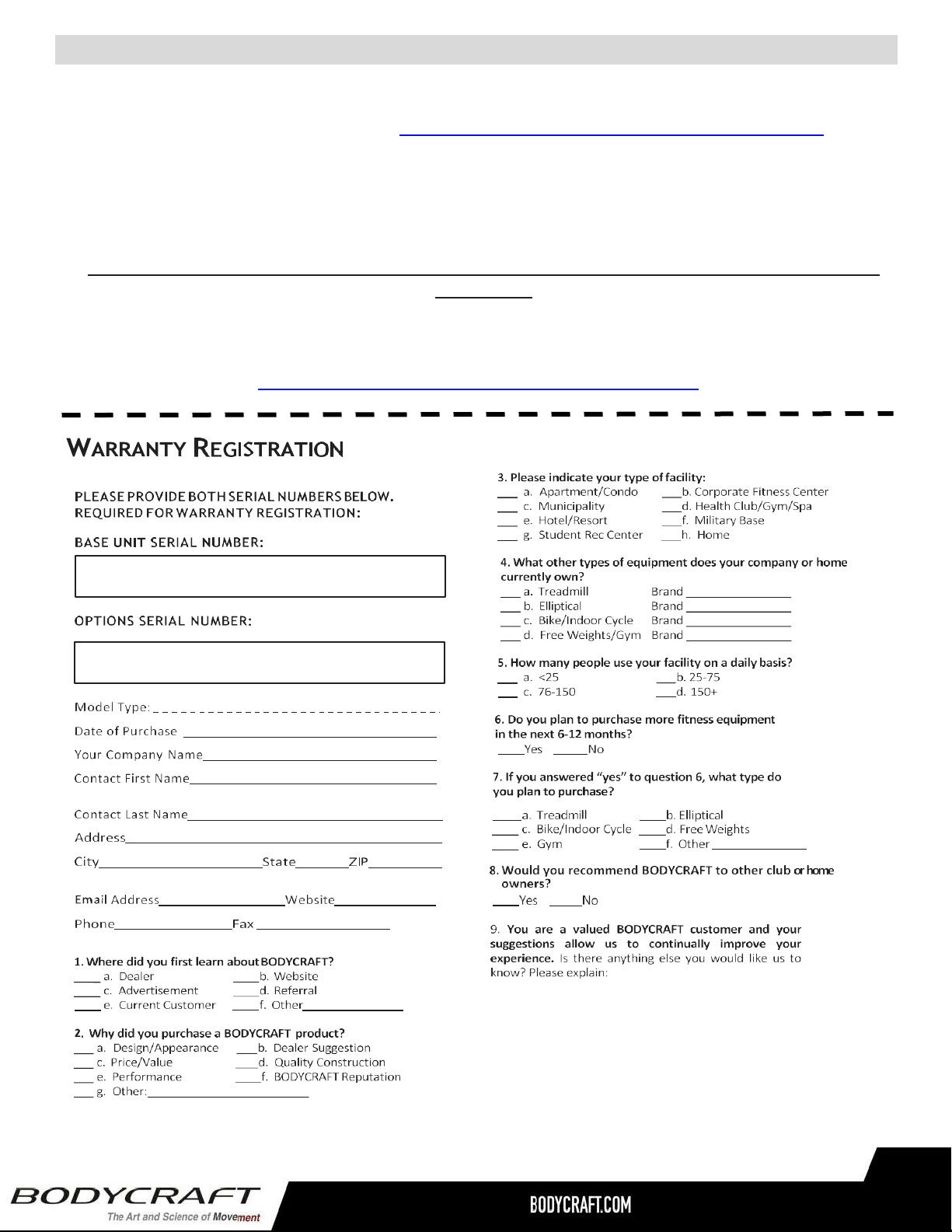
Thank you for purchasing a BODYCRAFT product. To validate the product warranty the fast and
easy way, please go on-line now to https://www.bodycraft.com/product-registration.html and
register your product. The information you provide will never be distributed to any other
individuals or agencies for any purpose. If you prefer to mail your warranty card, have the owner
of the product complete the information below and return it to BODYCRAFT within 30 days from
the date of equipment installation.
Please Note: Failure to register this product will result in no servicing or authorization of parts to
be shipped.
To mail your warranty information, please fill in the information below and mail to: Service
Dept., BODYCRAFT , 7699 Green Meadows Dr. Lewis Center, Ohio 43035 (or save postage
and register online at https://www.bodycraft.com/product-registration.html )
Warranty Registration - Strength
29