Loading ...
Loading ...
Loading ...
7
APPENDIX A:
Input Sensitivity Level Setting
Follow the steps below to adjust the input sensitivity of each amplifier
channel pair to achieve overall system balance.
Necessary Equipment
• Digital AC Voltmeter
• Sine-wave test tone recorded at 0 dBfs reference level in the frequency range to be amplied.
Do not use attenuated test tones (-10 dB, -20 dB, etc.).
Full range channel/amplier applications: 1 kHz
Subwoofer channel/amplier applications: 50 Hz
• Depending on your type of source unit, the sine-wave may be played via a CD, USB thumb drive, portable media player or
Bluetooth® audio source. Make sure to disable any EQ/DSP modes on your portable media player during level setting.
The Nine-Step Procedure
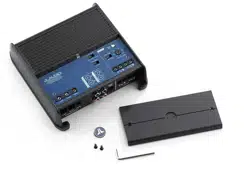
1. Disconnect the speaker(s) from the amplier’s speaker output connectors.
2. Turn o all processing (bass/treble, loudness, EQ, etc.) on the source unit, processors (if used) and amplier.
Set the fader control to center position and the subwoofer level control to 3/4 of maximum, if used.
3. Turn all “Input Sens.” controls all the way down.
4. Set the source unit volume to 3/4 of full volume. This will allow for reasonable gain overlap with moderate clipping at full volume.
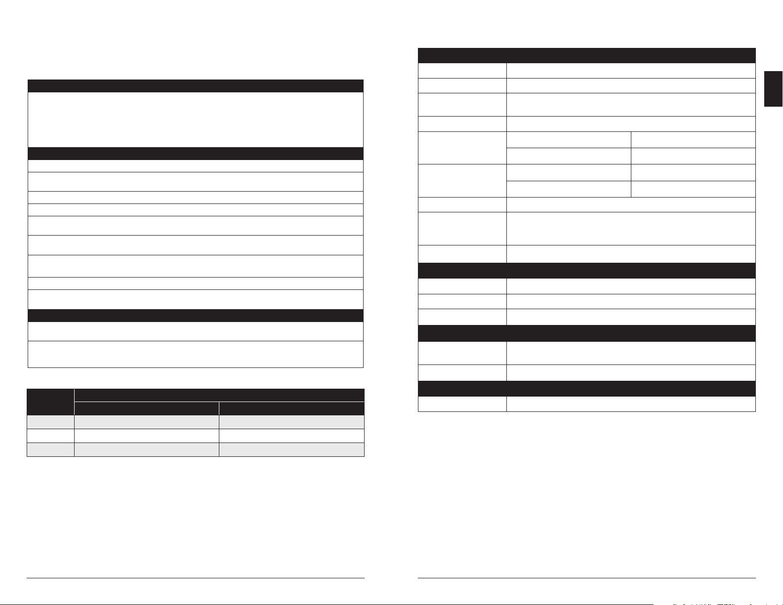
5. Using the chart below, determine the target voltage for input sensitivity adjustment according to the nominal impedance of the
speaker system connected to the amplier outputs.
6. Verify that you have disconnected the speakers before proceeding. Play a track with an appropriate sine wave (within the
frequency range to be amplied) at 3/4 source unit volume.
7. Connect the AC voltmeter to the speaker output terminals of the amplier. If the channel pair is operating in stereo, it is only
necessary to measure one channel. If bridged, make sure you test the voltage at the correct terminals (L+ and R–).
8. Increase the “Input Sens.” control until the target voltage is observed with the voltmeter.
9. Once you have adjusted each channel section to its maximum low-distortion output level, reconnect the speaker(s). The “Input
Sens.” controls can now be adjusted downward if the amplier requires attenuation to achieve the desired system balance.
IMPORTANT!
• Do not increase any “Input Sens.” setting for any amplier channel or channel pair in the system beyond the maximum level estab-
lished during this procedure. Doing so will result in audible distortion and possible speaker damage.
• It will be necessary to re-adjust the “Input Sens.” if any equalizer boost is activated after setting the “Input Sens.”
with this procedure. This applies to any EQ boost circuit, including source unit tone controls or EQ circuits. EQ cuts will not
require re-adjustment.
Nominal
Impedance
Target AC Voltage
Stereo Bridged
8Ω 17.3 V 34.6 V
4Ω 17.3 V 28.2 V
2Ω 14.1 V not recommended
SPECIFICATIONS
Amplier Section
Amplier Topology NexD™ Ultra-High Speed Class D
Power Supply Type Unregulated MOSFET Switching
Minimum Copper
Power/GND Wire
8 AWG
(Note: CCA/Copper Clad Aluminum wire is not recommended.)
Recommended Fuse 20 A
Rated RMS Power @ 14.4V,
<1% THD+N
75W x 2 @ 4 Ω 100W x 2 @ 2 Ω
150W x 1 @ 8 Ω Bridged 200W x 1 @ 4 Ω Bridged
Rated RMS Power @ 12.5V,
<1% THD+N
60W x 2 @ 4 Ω 90W x 2 @ 2 Ω
120W x 1 @ 8 Ω Bridged 180W x 1 @ 4 Ω Bridged
Frequency Response 12 Hz – 22 kHz (+0, -1dB)
S/N Ratio
(A-weighted, 20 Hz–20 kHz
noise bandwidth)
>104 dB (Referred to rated power),
>84 dB (Referred to 1W)
Damping Factor >150 / 50 Hz @ 4 Ω, >75 / 50 Hz @ 2 Ω
Input Section
Number of Inputs 2 (One Stereo Pair)
Input Type Differential-Balanced with RCA jack inputs
Input Voltage Range 200mV – 4V RMS
Signal Processing
Filter Type
Active, 12dB/octave, High-Pass or Low-Pass
(50 – 500 Hz), defeatable
Remote Level Control HD-RLC or MHD-RLC (optional). Full mute to 0 dB range.
Dimensions
L x W x H 6.85 in. x 7.09 in. x 2.05 in. (174 mm x 180 mm x 52 mm)
Due to ongoing product development, all specifications are subject to change without notice.
6 | JL Audio® - XDM200/2
EN
Loading ...
Loading ...
Loading ...