Loading ...
Loading ...
4 | JL Audio® - XDM200/2
5
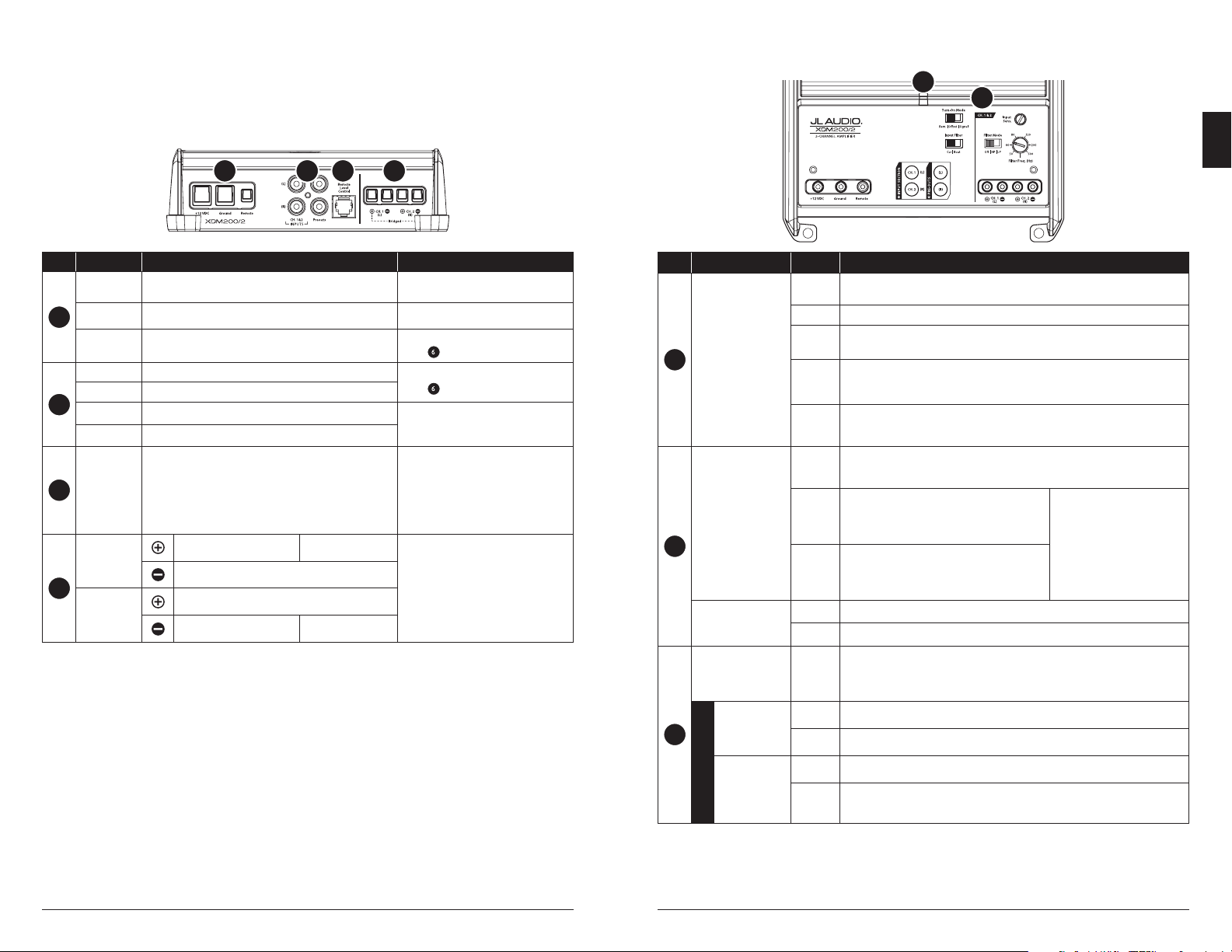
Connection Description Notes
1
+12 VDC Positive (+12V) Power Connection
• 4 AWG wire (8 AWG minimum)
• Install 20A fuse at (+) battery post
Ground Negative (GND) Ground Connection • 4 AWG wire (required)
Remote Positive (+12V) Activation Connection
• 18 – 12 AWG wire capacity
• See Turn On Mode for more info
2
CH. 1 Input Left Input Signal, Black RCA
• Accepts 200mV – 4V input voltage
• See Input Mode for more info
CH. 2 Input Right Input Signal, Red RCA
Preout 1 Left Pass-Through Preamp Signal, Black RCA
• Same signal that is connected to
CH. 1&2 inputs
• Unaected by the amplier’s lters
Preout 2 Right Pass-Through Preamp Signal, Red RCA
3
Remote Level
Control
Remote Level Controller Connection (optional)
(HD-RLC or MHD-RLC)
• Operates as an attenuator only:
Fully counter-clockwise = Level Muted
Fully clockwise = Level Unaected
• Multiple ampliers can be controlled
from a single HD-RLC using a non-
duplex phone line splitter and multiple
phone cables.
4
CH. 1 (L)
Speaker
Output
(+) Positive Speaker Output CH. 1&2 Bridged (+)
• Minimum impedance load:
Stereo mode ≥2 ohms
Bridged mode ≥4 ohms
• 16 – 8 AWG wire capacity
(–) Negative Speaker Output
CH. 2 (R)
Speaker
Output
(+) Positive Speaker Output
(–) Negative Speaker Output CH. 1&2 Bridged (–)
CONNECTIONS
Control (Function) Setting Description
5
Status LED
( indicates operating
status)
Flashing
Green
Amplier Powering Up, Audio Output Muted
Green On-Normal Operation, Active Audio Output
Red
On-Safe Mode, Over-Temperature Condition, Audio Output Reduced
• Reverts to normal operation when temperature returns to a safe level
Amber
(yellow)
On-Safe Mode, Over-Current Condition, Audio Output Muted
• May exhibit repetitive, audible ticking or thumping noise in the output
• Inspect for speaker/wire short circuit or low impedance
LEDs O
Amplier Turns O (unexpectedly), Low-Voltage Condition
• Occurs when battery or remote turn-on voltage drops below 10V
• Reverts to normal operation when voltage rises above 11V
6
Turn On Mode
( congures
activation method)
Remote
+12V Remote Turn-On (Preferred)
• Controlled by a switched +12V circuit or turn-on out-
put of your source unit/OEM interface
Oset
DC Oset-Sensing (Automatic)
• Turns On by detecting the presence of small DC
signal in OEM audio outputs and turns O after
the signal is removed
• Designed for high-level
(speaker) signals only
• Detects input signal from
CH. 1 (L) only
• Using DC Oset or Signal
Sensing methods will turn the
“Remote” terminal into a +12V
turn-on output.
Signal
Signal-Sensing (Automatic)
• Turns On by detecting full-range OEM audio
signals and turns OFF after the signal is removed
(within 30 seconds)
Input Filter
( congures input
lter application)
Car Select for most installations (automotive or marine)
Boat Select if experiencing interference from high-current mechanical switches/devices
7
Input Sens.
( adjusts each
channel pair’s input
stage)
Variable
Use to match the source unit’s output voltage with the inputs of each pair of amplier
channels. See Appendix A for detailed information.
CH. 1&2
Filter Mode
( congures
the lter of CH.
1&2)
O Filter defeated; passes full range of frequencies present at the inputs
HP Attentuates frequencies below the CH. 1&2 “Filter Freq. (Hz)” dial, at a rate of 12dB/octave
Filter Freq. (Hz)
( adjusts lter
cuto frequency)
LP Attentuates frequencies above the CH. 1&2 “Filter Freq. (Hz)” dial, at a rate of 12dB/octave
Variable
Use to adjust the cuto frequency of channel 1&2’s active lter,
from 50 Hz – 500 Hz / 12dB per octave
CONTROLS
1 2 3 4
6
5
EN
Loading ...
Loading ...
Loading ...