Loading ...
Loading ...
Loading ...
The awe ower s shpped fiy asee'f_bed except fo the ban,,
die Ibrattece_tei @vecenbo mdand_uIchces oied Ai
terns ale packed ane shipped in one costa nor:
t. Ope the carton.
2_ Reme,_ tie grass ca/char, hande assembl% d_ve cor_t ol
md and uppe_ caleb cetltre[ rod
$ Remove the ca dbee d p_ekir g mate'lal item the carlon
4 Cut the back pane ef the ear o_, and fold devm fat
5 Ro! he,rowe o tofthees ton
6 Daeonnect the spa_ pig wrafiom the park:pbg, i:emove
the hardwa e b!, _hee reco_*qect the spark ph,g wire to the
NOTE Reference to iet@ Hght sde of the mower is made fr(m
the _.se¢s posit or1at the hande _acng _orward
1_ b'iete the hande assembly:
NOTEs Six be[s a_d _us _a usedte secun the hande
assembly two bole 8d 'sits e_{, facto y neta!ad the
t resin r',g ate a_d WtS are irnluded n the hardware kit
A Remove the bet andrwteee_F',g _e ('4tsdeia Ida
breech, the e,warhande md[/ erbraso(seeFgure 1)
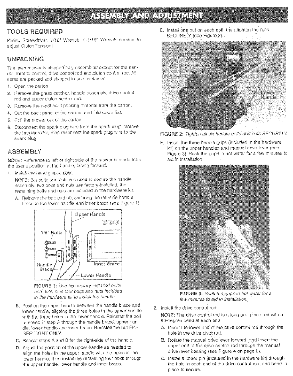
_I@URE 2: T_gh_enaft six Sundae bo£s an_de_Jte;SfCURFLX
R Instal the three handle grps (included n the hardware
ki_) on the upper ban_les a_d manes drive _eve (see
Fgure 3) Soak the grips il hot water foa few minutes to
aid ri }nstalat on.
_@URE ! : Use two tac£)o'fns£_t_ed _Jo#e
and ys£s, p£,s teur }o _aand nt,l,s fuc ud_vd
m t,_,ehardware kit to inaks# _hehanda_
B. Posit on the _.pp_ r a_da between tee h_nde b,aee a_d
owe_ handle agnlg the three he/us n, the uppe__! andre
with the three holes n the Iowa handle Re asta the bet
_emrwed _nstep A through the handle brace, up[let ham
de, Ower hande and nner bruce. RenstaJthe nt,t FN-
GER TGHT ONLY}
O: Repeat s_eps A ard
D,, Adlu,st _he posit en o_the upp®_"hande as needed to
a!gn the hoes in tke upp , handle wth the heies lethe
lower handle, then nstai the rema nir_g*uu_ bets threugh
the upper handle, Iowa[ handle and nner brace.
@w £t_)sutes to a/d i_ instal/at@¢t
2 nsta _he ddve control rod:
NOT_r he dive ear trol ied is a long one@ere rod win a
90..degree bend at ech end
A. tnse_t the kw_eJ"end o the drve centfoi rod through the
B, Rotate 'the manua_ ddve lev÷r farwa_d_ and snort the
upper end of the drive control rod through the menus
drive keve_ bear ng (see Fgure 4 on page 6)
6. Install a cotter pn ([nciuded n the hardware kit) through
the hoe in each end of the ddve control rod and bend in
p_ace tn se_;t_e,
Loading ...
Loading ...
Loading ...