Loading ...
Loading ...
Loading ...
21
General Installation Guidelines
Due to our policy of continuous product innovation, some specifications may change without notification.
©LG Electronics U.S.A., Inc., Englewood Cliffs, NJ. All rights reserved. “LG” is a registered trademark of LG Corp.
GENERAL INSTALLATION GUIDELINES
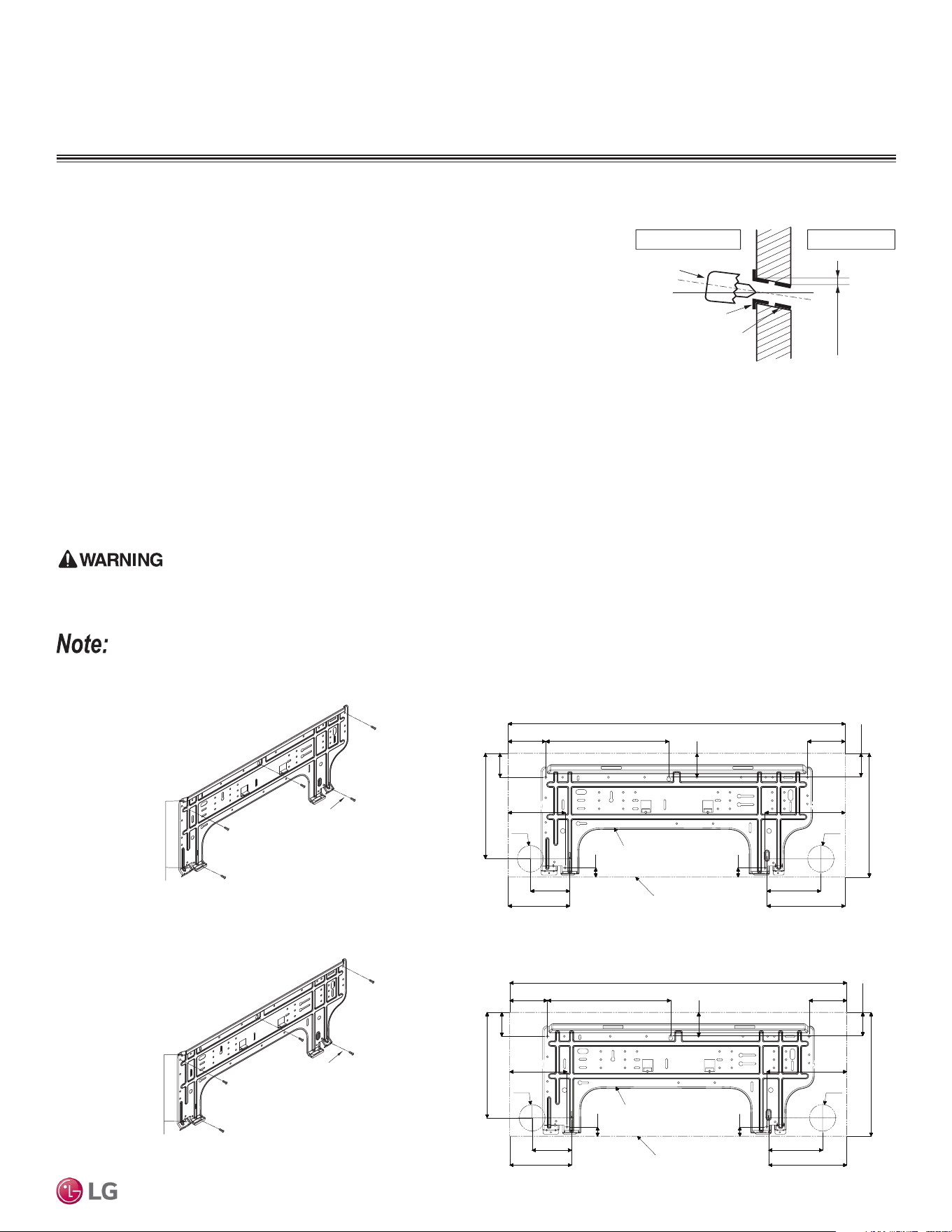
Drilling the Piping Hole in the Wall
Follow all piping clearance recommendations.
1. Using a 2-9/16 inch hole core drill bit, drill a hole at either the right or left side of the
wall mounting, pre-chosen following installation guidelines and application needs.
• The slant of the hole must be 3/16” to 5/16 inches from level with the slant being
upward on the indoor unit side and downward on the outdoor unit side.
2. Finish off the newly drilled hole as shown with bushing and sleeve covering to pre-
vent damage to the insulation and piping.
(3/16"~5/16")
Indoor
WALL
Outdoor
Bushing
Core Drill
Sleeve
Figure 14: Mega 115V Wall Mount Indoor Unit Installation Plate Dimensions.
Indoor Unit Mounting
Mounting the Installation Plate to the Wall
Follow the procedure below and general best practices when mounting the indoor unit’s installation plate to a wall.
1. Depending on the model, the wall mounted indoor unit is shipped with the installation plate attached to its back. To remove, unscrew the
one (1) screw that holds the installation plate to the back of the indoor unit.
2. Align the centerline using a leveling tool. Measure the wall and mark the centerline.
3. Attach the installation plate to the wall following the measurements and marks. Use the type “A” screws that are factory-supplied with the
plate. If mounting the unit on a concrete wall, use field-supplied anchor bolts.
4. Observe all rear piping clearances when drilling into the wall.
• When choosing a location for the wall mount plate, be sure to take into consideration routing of wiring for power outlets within the wall.
Contacting wiring can cause serious bodily injury or death.
• Use caution when drilling holes through the walls for the purposes of piping connections. Power wiring can cause serious bodily injury or death.
Select the location carefully. Unit must be anchored to a strong and solid wall to prevent unnecessary vibration.
Figure 12: Drilling Piping Hole.
Figure 13: Mega 115V Wall Mount Indoor Unit Installation Plate.
Installation Plate
32-15/16 (837)
2-15/32
(63)
12-1/16 (306)
3-21/32 (93)
10-11/32 (263)
5-31/32 (152)
3-27/32 (98)
5-9/32 (134)
12-1/8 (308)
3-11/16 (94)
7-5/8 (194)
Unit Outline
29/32 (23)
Ø2-9/16 (65)
5-19/32 (142)
Ø2-9/16 (65)
7-27/32 (199)
29/32 (23)
2-15/32 (63)
2-17/32 (64)
Figure 15: Mega, Standard Efciency 9K and 12K Wall Mount
Indoor Unit Installation Plate.
Figure 16: Mega, Standard Efciency 9K and 12K Wall Mount Indoor Unit
Installation Plate Dimensions.
Installation Plate
Chassis
Hook
Type "A" Screws
Installation Plate
Chassis
Hook
Type "A" Screws
Installation Plate
32-15/16 (837)
2-15/32
(63)
12-1/16 (306)
3-21/32 (93)
10-11/32 (263)
5-31/32 (152)
3-27/32 (98)
5-9/32 (134)
12-1/8 (308)
3-11/16 (94)
7-5/8 (194)
Unit Outline
29/32 (23)
Ø2-9/16 (65)
5-19/32 (142)
Ø2-9/16 (65)
7-27/32 (199)
29/32 (23)
2-15/32 (63)
2-17/32 (64)
Loading ...
Loading ...
Loading ...