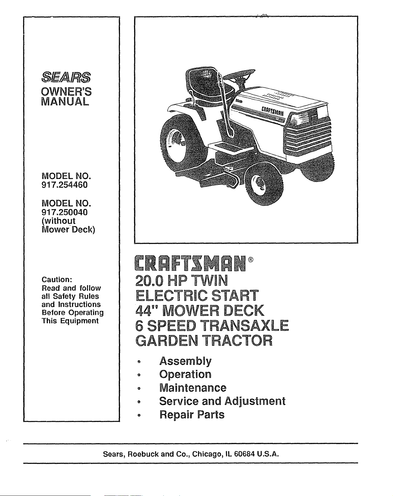
OWNER'S
MANUAL
MODEL NO.
917.254460
MODEL NO.
917.250040
(without
_ower Deck)
Caution:
Read and follow
all Safety Rules
and Instructions
Before Operating
This Equipment
®
O
g
Q
O
AssembBy
Operation
Maintenance
Service and Adjustment
Repair Parts
.ooK sv.BoLTo ....I
out,MPORTA.T P.ECAU-!
T,O.S.,TMEA.S-A rE. O.;BE- m
co.EALE. ,you.SA E.,S,.- !
VOLVED, ......
M
CAUTION: LOOK FOR THIS WORD TO POINT OUT
IMPORTANT EQUIPM ENT PRECAUTIONS
NOTE: LOOK FOR THIS WORD TO POINT OUT IM-
PORTANT INFORMATION ABOUT THE OPERATION
AND PERFORMANCE OF YOUR TRACTOR
RULES FOR SAFE OPERATION
WARNING: This unit is equipped with an internal combustion engine and should not be used on or near any unimproved forest covered,
brush covered or grass covered land unless the engine s exhaust system is equipped with a spark arrestor meetingappticable local or area
laws (ff any). If a spark arrestor is used, it should be maintained in effective working order by the operator, (See REPAIR PARTS for part
number identificatlon)o
in the State of California the above is required by law (Section 4442 of the California Public Resources Code). Other States may have similar
laws_ Federal laws apply on federal lands
t,. Know the controls and how to stop quickly. READ THIS
OWNER S MANUAL and instructions furnished with attach-
ments_
2 Do not allow children to operate the machine_ Do not allow
adults to operate it without proper instruction,
3, Do not carry passengers,, Do not mow when children and
others are around,
4,, Always wear substantial footwear. Do not wear loose fitting
clothing that could get caught in moving parts,.
5, Keep your eyes and mind on your tractor, mower, and the
area being cuL Do not let other interests distract you.
6_ Do not attempt to operate your tractor or mower when not in
the driver's seat,,
7, Always get on or off your tractor from the operatoi"s left hand
side_
8 Clear the work area of objects (wire, rocks, etc ) which might
be picked up and thrown,.
9,. Disengage all attachment clutches before attempting to start
the engtne,
t 0, Disengage power to attachments and stop the engine before
leaving the operator's position,
1i, Disengage power to mower, stopthe engine, and disconnect
spark plug wire(s) from spark plug(s) before cleaning, making
an adjustment, or repair. Be careful to avoid touching hot
muffler or engine components.
12 Disengage powerto attachments when transporting or not in
USer
13, Take al! possible precautions when leaving the vehicle
unattended, Disengage the power take-off, lower the attach-
ments, shift into neutral, set the parking brake, stop the
engine, and remove the key,
14 Do not stop or start suddenly when going uphitl or downhill,.
Mow up and down the face of slopes (not greater than 15°),
never across the face. Referto page55..
15. Reduce speed on slopes and make turns gradua!lyto prevent
tipping or loss of control, Exercise extreme caution when
changing direction on slopes.
16 While going up or down slopes, place gear shift control lever
in 1st gear position to negotiate the slope without stopping..
17. Never mow in wet or slippery grass, when traction is unsure,
or at a speed which could cause a skid.
18_ Stay alert for holes in the terrain and other hidden hazards.
Keep away from drop-offs_
19 Do not drive too close to creeks, ditches, and public high-
waysr.
20. Exercise special care when mowing around fixed objects in
order to prevent the blades from striking them. Never delib-
erately run tractor or mower into or over any foreign objects..
21. Never shift gears until tractor comes to a stop.
22. Never place hands or feet under the mower, in discharge
chute, or near any moving parts while tractor or mower =s
running..Always keep clear of discharge chute.
23 Use care when pulling loads or using heavy equipmenL
a.. Use only approved drawbar hitch points..
b. Limit loads to those you can safely control
2
c,, Do not turn sharply, Use care when backing,
d,_ Use counterweight or wheel weights when suggested in
owner's manual
24 Watch out for traffic when crossing or near roadways
25, When using any attachments, never direct discharge of
material toward bystanders nor allow anyone near the ve-
hicle while in operation,
26,, Handle gasoline with care - it is highly flammable,
a, Use approved gasoline containers,
b,, Never remove the fueF cap of the fuel tank or add
gasoline to a running or hot engine or an engine that has
not been allowed to cool for several minutes after run-
ning,, Never fill tank indoors Always clean up spilled
gasoline.
c_ Open doors if the engine is run in the garage - exhaust
fumes are dangerous. Do not run the engine indoors.
27. Keep the vehicle and attachments in good operating condi-
tion, and keep safety devices in place and working,.
28,, Keep all nuts, bolts, and screws tight to be sure the equip-
ment is in safe working condition,
29, Never store the equipment with gasoline in the tank inside a
building where fumes may reach an open flame or spark,
Allow the engine to cool before storing tn any enclosure,.
30_ To reduce fire hazard, keep the engine free of grass, leaves,
or excessive grease,, Do not clean product while engine is
running.
3t._ Except for adjustments, DO NOToperate engine if air cleaner
or cover directly over carburetor air intake is removed
Removal of such part could create a fire hazard.
32° Do not operate without a muffler, or tamper with exhaust
system,, Damaged mufflers or spark arrestors could create a
fire hazard_ Inspect periodically and replace if necessary.
33 The vehicl,e and attachments should be stopped and in-
spected for damage after striking a loreign object, and the
damage should be repaired before restarting and operating
the equipmenL
34° Do not change the engine governor settings or overspeed the
engine; severe damage or injury may result,
35 When using the vehicle with mower, proceed as follows:
a, Mow only in daylight or in good artificial light,
b,, Shut the engine off when unclogging chute,
c Check the blade mounting botts for proper tightness at
frequent intervals_
36. Do not operate the mowerwithout the entire grass catcher,
on mowers so equipped, or the deflector shield in place,,
37. Disengage power to mower before backing up, Do not mow
in reverse unless absolutely necessary and then only after
careful observation of the entire area behind the mower.
38. Under normal usage the grass catcher bag material is subject
to deterioration and wear,, It should be checked frequently for
bag replacement Rep!acement bags should be checked to
ensure compliance with the original manufacturer's recom-
mendations or specifications.
CONGRATULATIONS on
Garden Tractor.. It has beer_ ur
yo purchase
of a Sears
designed, engineered and
manufactured to give you the best possible dependability
and performance° Should you experience any problem
you cannot easily remedy, please contact your nearest
Sears Service DepartmenL We have competent, well-
trained technicians and the proper tools to service or
repair this uniL
MAINTENANCE AGREEMENT
A Sears Maintenance Agreement is available on this
product., See the nearest Sears store or service center
for details.,
SERIAL
NUMBER
DATE OF PURCHASE
THE SERIAL NUMBER WILL BE FOUND ON THE
MODEL PLATE UNDER THE SEAT.
YOU SHOULD RECORD THESE NUMBERS AND
KEEP FOR FUTURE REFERENCE.
CUSTOMER RESPONSIBILITIES
Read and retain this manual,. Study and observe the safety rules,. Always use care when using your tractor_ Always
keep your tractor and mower clean., Follow a regular schedule in maintaining, caring for, and using your tractor.. A well
cared for tractor will run better and last longer.
A TTACHMENTS
This unit can use many attachments now available at your Sears store_ See pages 53_54 for a list of available
attachments..
LIMITED TWO YEAR WARRANTY
ON ELECTRIC START RiDiNG EQUIPMENT
For two years from date of purchase, when this riding equipment is maintained, lubricated, and tuned up according
to the operating and maintenance instruction in the owner's manual, Sears will repair free of charge any defect in
material or workmanship in this electdc start riding equipment,.
This warranty excludes blade(s), blade adapter(s), spark plug(s), air cleaner and belt(s), which are expendable and
become wom during normal use.
This warranty does not cover:
o Tire replacement or repair caused by punctures from outside objects (such as nails, thorns, stumps, or
glass); and
- repairs necessary because of operator abuse or negligence, including the failure to maintain the equip-
ment according to instructions contained in the owner's manual; and
- riding equipment used for commercial or rental purposes°
FULL 90 DAY WARRANTY ON BATTERY
For 90 days from the date of purchase, if any battery included with this riding equipment proves defective in material
or workmanship and our testing determines the battery will not hold a charge, Sears wilt replace the battery at no
charge.
WARRANTY SERVICE 1S AVAILABLE BY CONTACTING THE NEAREST SEARS SERVICE CENTER DEPART-
MENT IN THE UNITED STATES. This warranty applies only while this product is in use in the United States.
This warranty gives you specific legal rights, and you may also have other dghts which may vary from state to state
SEARS, ROEBUCK and CO., D/731CR-W, Sears Tower, Chicago, IL 60684
3
iNDEX
A
Adjustments:
Brake ...................................................16
Carburetor ...........................................20
Mower"
Front- To-Rear ...........................22
Side- To-Side ...............................22
Height ...............................................21
Throttle Control Cable ...................20
Shifter Shaft ..........................................25
Air Cleaner° ...................................................17
Air Screen, Engine ...................................18
Assembly .........................................................5-10
Attachments .............................................53-54
B
Battery:
Charging ..........................................7, 20
Cleaning ..................................................17
Installation ....................................................8
Levels ...............................................................7
Preparation ................................................7
Staffing with Weak Battery ......20
Storage ........................................................25
Terminals ...............................................17
Belt,:
Motion Drive
Removal/Replacement ........24
Mower Drive
Installation .........................................10
Removal ..........................................22
Mower Blade Drive
Removal/Replacement ......23
Blade:
Sharpening ............................................16
Replacement ...............................................24
Brake Adjustment ........................................16
C
Carburetor Adjustment ............................20
Controls, Tractor', ....................................! I
Cutting Leve!, Mower ............................10
E
Engine,:
Air Cleaner .......................................17
Air Screen ..............................................18
Cooling fins .............................................18
Oil Change ..............................................15
Oil Level ...................................................15
Oil Type ...........................................................I5
Repa# Parts ...............................42-50
Starting ......................................................12
Storage .................................................25
F
Filter:
A# Cleaner. ................................................17
Fuel ..............................................................18
Fuel:
Type ...............................................................12
Storage ..................................................25
Fuse ....................................................................2I
H
Hood Removal/Installation ...................21
L
Leveling Mower Deck .......................21-22
Lubrication.:
Chaff ..............................................................19
Tractor Pivot Points .........................!8
M
Maintenance ..............................................15-19
Air Cleaner. .................................................17
Foam Pre-cleaner. .................17
Air Screen, Engine ..............................18
Battery .........................................................17
Blade Sharpening ...........................16
Brake Adjustment ............................t6
Engine Oil ................................................15
Fuel Filter ....................................................18
Lubrication Chart ..........................19
Spark Plugs ................................................18
Tire Care ..............................................16, 24
Mower:
Adjustment, Front-to-Rear ........22
Adjustment, Side-to-Side ............22
Height ......................................................21
Blade Sharpening ..............................16
Blade Replacement ........................24
Cutting Level ..........................................10
Installation ................................................10
Operation ................................................t3
Removal .....................................................22
Mowing Tips .......................................................14
Muffler'. ...............................................................18
Spark Arrester .............................2,32
0
Oil:
Cold Weather Conditions ............15
Engine .......................................................15
Storage ....................................................25
Operation .......................................................1 i- 14
Operating Your Mower .................13
Operating Your Tractor ...............13
Starting the Engine .........................12
Stopping Your Tractor ...................12
Tractor Operation on Hills ........14
Options,:
Spark Arrester ..............................2, 32
Attachments ................ 53-54
P
Parking Brake ..............................................11
Parts Bag .................................................5-6
Parts, Replacement/Repair ......29-50
R
Repa# and Adjustments ...................19-25
Blade ..........................................................24
Carburetor,. ............................................20
Fuse ....................................................................21
Hood Removal/Installation .......2 I
Motion Drive Belt
RemovaYReplacement ......24
Mower Drive Belt
installation ..........................................10
Removal ..............................................22
Mower Blade Drive Belt
Removal/Replacement ......23
Mower Adjustment
Front- to-Rear ............................22
Side-to-Side .....................................22
Height ..............................................21
Mower Removal ...............................23
Tire Care ............................................16, 24
Repair Parts ..............................................29-50
S
Safety Rules ............................................................2
Seat .................................................................................7
Service Record .............................................27
Slope Guide Sheet ........................................55
Spark Plugs ..................................................18
Speed Control Chart .................................13
Staffing the Engine ......................................12
Steering Wheel .................................................8
Stopping the Tractor ...............................12
Storage ...................................................................25
T
Throttle Control Cable
Adjustment .............................................20
Tires ................................................16, 24
Trouble Shooting Chart ....................26-27
Transaxle :
Repair Parts ..............................40- 41
Shifter Adjustment ..........................25
W
Warranty ..............................................................3
Wiring Schematic .................................28
4
ASSEM LY
To assemble and adjust your tractor you will need:
(2) 7/!6" Wrenches
(1) 3/4"" Wrench
(1) 9/16" Wrench
(1) 1/2" Wrench
(I) 3/4" Socket
(2)
Ratchet wrench
Tire Pressure Gauge
Screwdriver
Utility Knife
11/16 wrench
NOTE: RIGHT HAND (R.H) AND LEFT HAND (L.H..)
ARE DETERMINED FROM OPERATOR'S POSITION
WHILE SEATED ON THE TRACTOR.
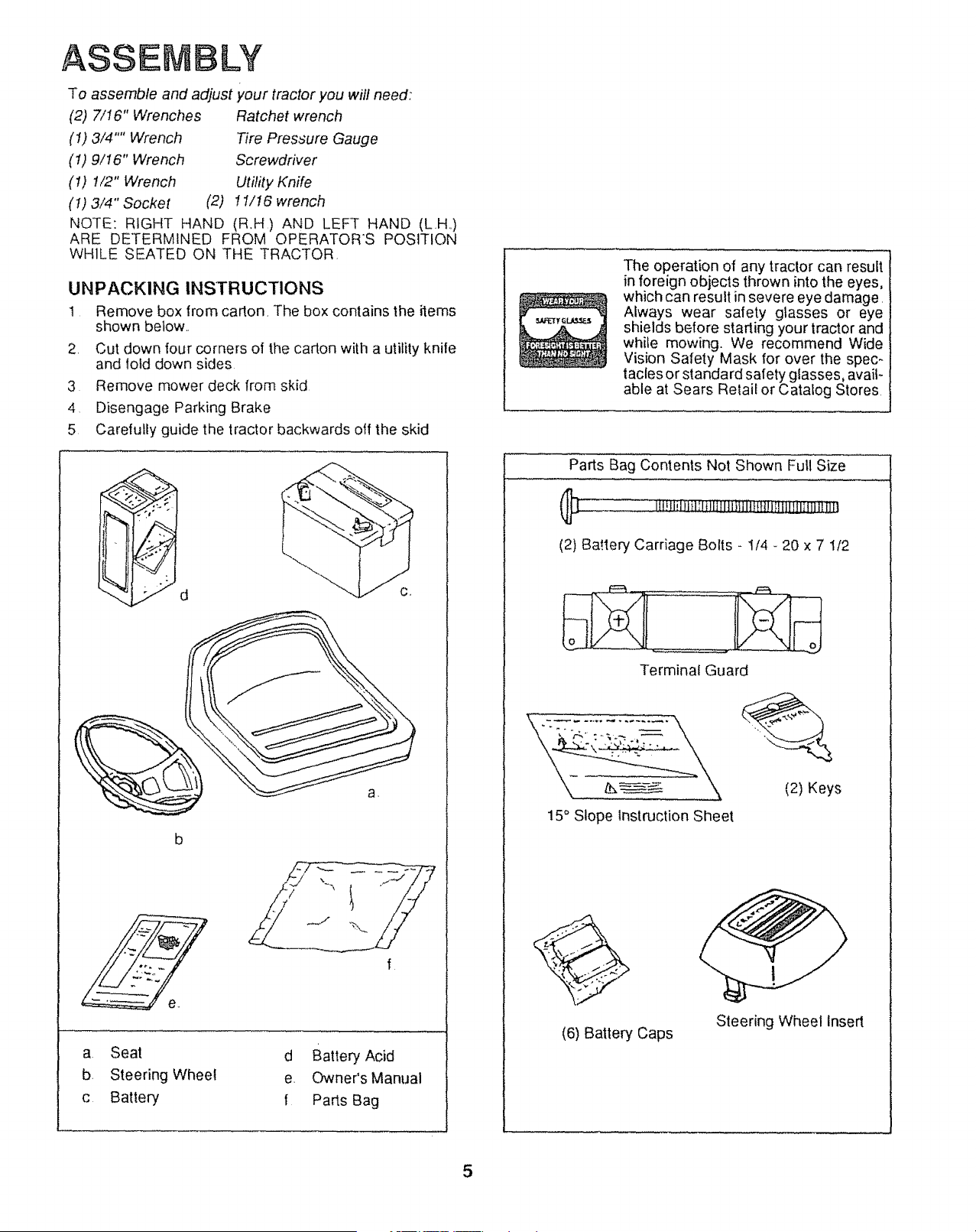
UNPACKING INSTRUCTIONS
1 Remove box from carton. The box contains the items
shown below..
2. Cut down four corners of the carton with a utility knife
and lold down sides
3 Remove mower deck from skid
4 Disengage Parking Brake
5 Carefully guide the tractor backwards off the skid
d
J C,
a.
b
/ ""' I
'_,, ,,
a Seat
b Steering Wheel
c Battery
d Battery Acid
e. Owner's Manual
t Parts Bag
The operation of any tractor can result
in foreign objects thrown into the eyes,
which can result in severe eye damage.
Always wear safety gtasses or eye
shields before starling your tractor and
while mowing. We recommend Wide
Vision Safety Mask for over the spec-
tacles or standard safety glasses, avail_
able at Sears Retail or Catalog Stores
Parts Bag Contents Not Shown Full Size
(2) BaMery Carriage Bolts - 1/4 - 20 x 7 112
Terminal Guard
15° Slope Instruction Sheet
(2) Keys
(6) Battery Caps
Steering Wheel Insert
ASS
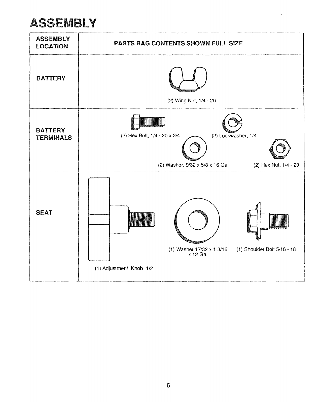
ASSEMBLY
LOCATfON
BATTERY
BATTERY
TERMINALS
SEAT
LY
PARTS BAG CONTENTS SHOWN FULl, SiZE
(2) Wing Nut, 1/4- 20
(2) Hex Bolt, 1/4 - 20 x 3/4
(2) Lockwasher, 1/4
@
(2) Washer, 9/32 x 5/8 x 16 Ga
(2) Hex Nut, 1/4 - 20
(1) Washer 17/32 x ! 3/16
x12Ga
(1} Shoulder Bolt 5/16 - t8
(1) Adjustment Knob 1/2
6
ASSEMBLY
WEAR EYE AND FACE SHIELD.
WASH HANDS OR CLOTHING IMME-
DIATELY IF ACCIDENTALLY IN CON-
TACT WITH BATTERY ACiDo
DO NOT SMOKE, FUMES FROM
CHARGED BATTERY ACID ARE EX-
PLOSIVE°
NOTE: THIS TRACTOR IS EQUIPPED WITH AN OP-
ERATOR PRESENCE SENSING SWITCH. ANY AT-
TEMPT BY THE OPERATOR TO LEAVE THE SEAT
WITH THE ENGINE RUNt,lING AND ATTACHMENT
CLUTCH ENGAGED WILL SHUT OFF THE ENGINE
1. Prepare Battery
READ INSTRUCT!ONS INCLUDED WITH THE BATTERY
VENT CAPS FOUND IN BAG OF PARTS. ALWAYS WEAR
GLOVES, CLOTHING AND GOGGLES TO PROTECT
YOUR HANDS, SKIN AND EYES
a.. Fill and charge battery (before installing).. NOTE:
SEE DETAILED INSTRUCTIONS PACKAGED
WITH BATTERY VENT CAPS IN BAG OF PARTS.
NOTE: OVERCHARGING WILL SHORTEN BATTERY
LIFE
b
C
Fill battery with battery acid to bottoms of tubes in
cells (Fig 1). DO NOT OVERFILL. OVERFILLING
WILL RESULT IN DAMAGE TO TRACTOR.
Check level of battery acid after 30 minutes, Add
additional battery acid if necessary. NOTE: PRESS
VENT CAPS INTO BATTERY UNTIL FASTENED
SECURELY
NOTE: OBSERVE SAFETY PRECAUTIONS, LISTED
1N BOX ABOVE, REQUIRED FOR BATTERY CHARG-
ING..
d Charge battery at a rate of six amperes for one
hour,
e_ Neutralize excess battery acid (from filling battery)
for disposal by. adding it to Z4 litres (2 gallons) of
water in a 19litres (5 gal!on) plastic container. Stir
with a wooden or plastic paddle while adding
baking soda until the addition of more soda causes
no more foaming..
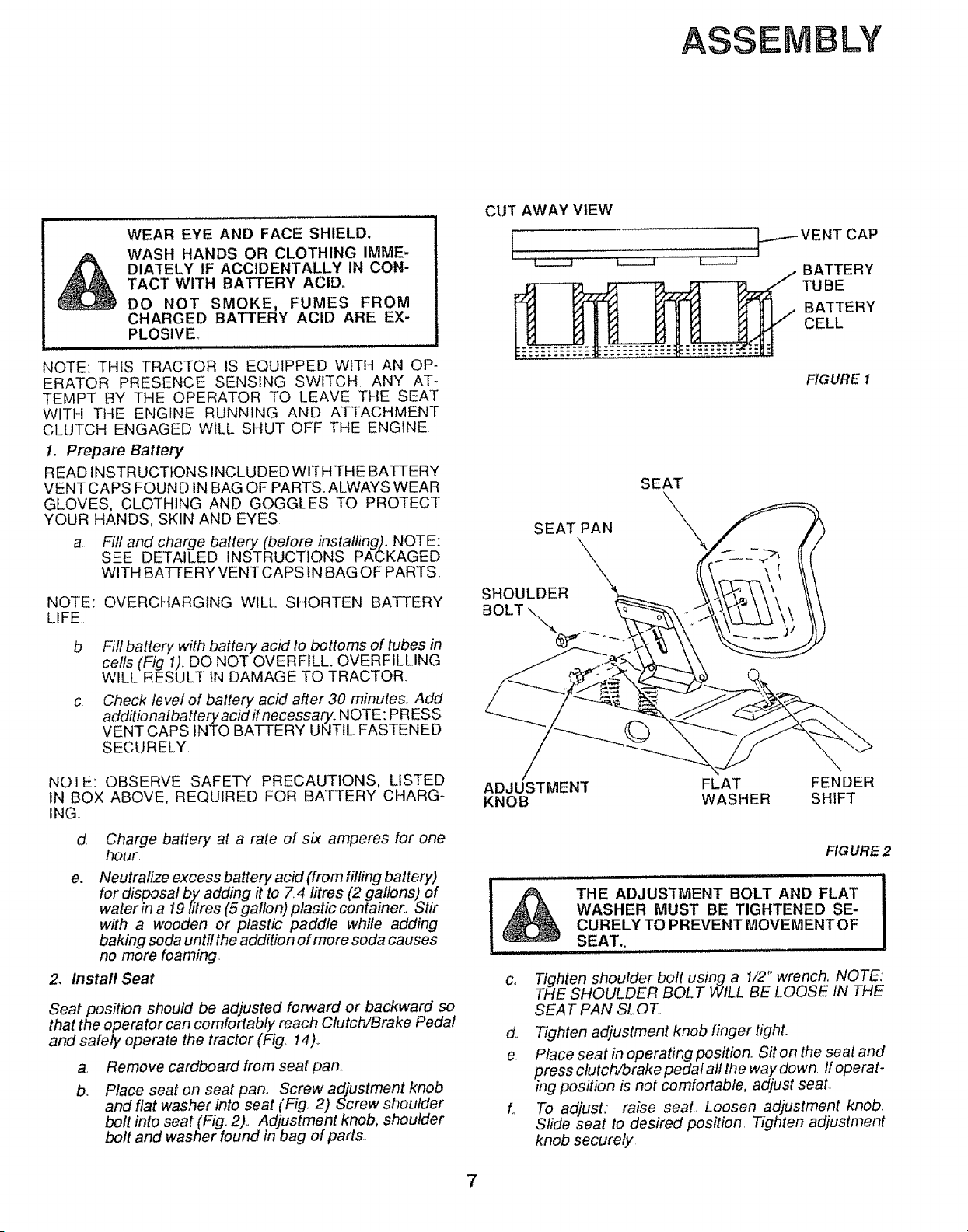
2. Install Seat
Seat position should be adjusted forward or backward so
that the operator can comfortably reach Clutch/Brake Pedal
and safely operate the tractor (Fig.. 14)_
a,,
b.
Remove cardboard from seat pan..
Place seat on seat pan, Screw adjustment knob
and flat washer into seat (Fig. 2) Screw shoulder
bolt into seat (Fig, 2),. Adjustment knob, shoulder
bolt and washer found in bag of parts..
CUT AWAY VIEW
--- VENT CAP
BATTERY
TUBE
BATTERY
CELL
FIGURE 1
SEAT
SEAT PAN
/
ADJUSTMENT
KNOB
FLAT FENDER
WASHER SHIFT
FIGURE 2
THE ADJUSTMENT BOLT AND FLAT
WASHER MUST BE TIGHTENED SE-
CURELY TO P REVENT MOVEMENT OF
SEAT.,
c., Tighten shoulder bolt using a I/2" wrench. NOTE:'
THE SHOULDER BOLT WILL BE LOOSE IN THE
SEAT PAN SLOT.
d.. Tighten adjustment knob finger tight..
e Place seat in operating position.. Sit on the seat and
press clutch/brake pedal all the way down If operat-
ing position is not comfortable, adjust seat
L To adjust: raise seal.. Loosen adjustment knob.
Slide seat to desired position. Tighten adjustment
knob securely..
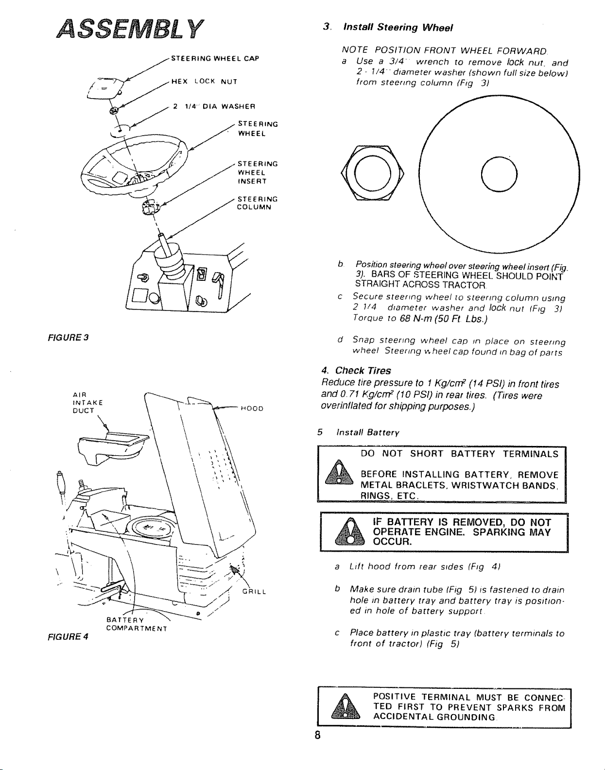
A SSEMBL Y
STEERING
WHEEL
iNSERT
FIGURE 3
AIR
INTAKE HOO0
DuCT
,\
FIG URE 4
3. Install Steering Wheel
NOTE POSITION FRONT WHEEL FORWARD
a Use a 3/4 wrench to remove tock nut and
2 - t/4-" diameter washer (shown full size below)
from steertng column (Fig 3t
G
b. Position steering wheel over.steering wheel insert (Fig,,
3), BARS OF STEERING WHEEL SHOULD POINT
STRAIGHT ACROSS TRACTOR
c Secure steering wheel to steermg column usmg
2 I/4 dtameter washer and fock nut (F_g 3)
Torque to 68 N-m (50 Ft Lbs,.)
d Snap steenng wheel cap in place on steering
wheel Steermg v_heei cap found tn bag of parts
4. Check Tires
Reduce tire pressure to I Kg/crrF (14 PSI) in front t#es
and O,71 Kg/cn'F (10 PSI) in rear tires.. (Tires were
overinftated for shipping purposes,.)
5 Install Battery
!_ DO NOT SHORT BATTERY TERMINALS
BEFORE INSTALLING BATTERY, REMOVE
METAL BRACLETS. WRISTWATCH BANDS,
.... RINGS.:,ooETC ' : ................................
I&..... I
tF BATTERY IS REMOVED, DO NOT
OPERATE ENGINE. SPARKING MAY
OCCUR.
a Lift hood from rear srdes (F_g 41
b Make sure drain tube (Fig 5) is fastened to drain
hole in battery tray and battery tray is position.
ed in hole of battery support
c Place battery in plastic tray (battery terminals to
front of tractor) (Fig 5)
1
POSITIVE TERMINAL MUST BE CONNEC,- I
TED FIRST TO PREVENT SPARKS FROM
1
ACCIDENTAL GROUNDING
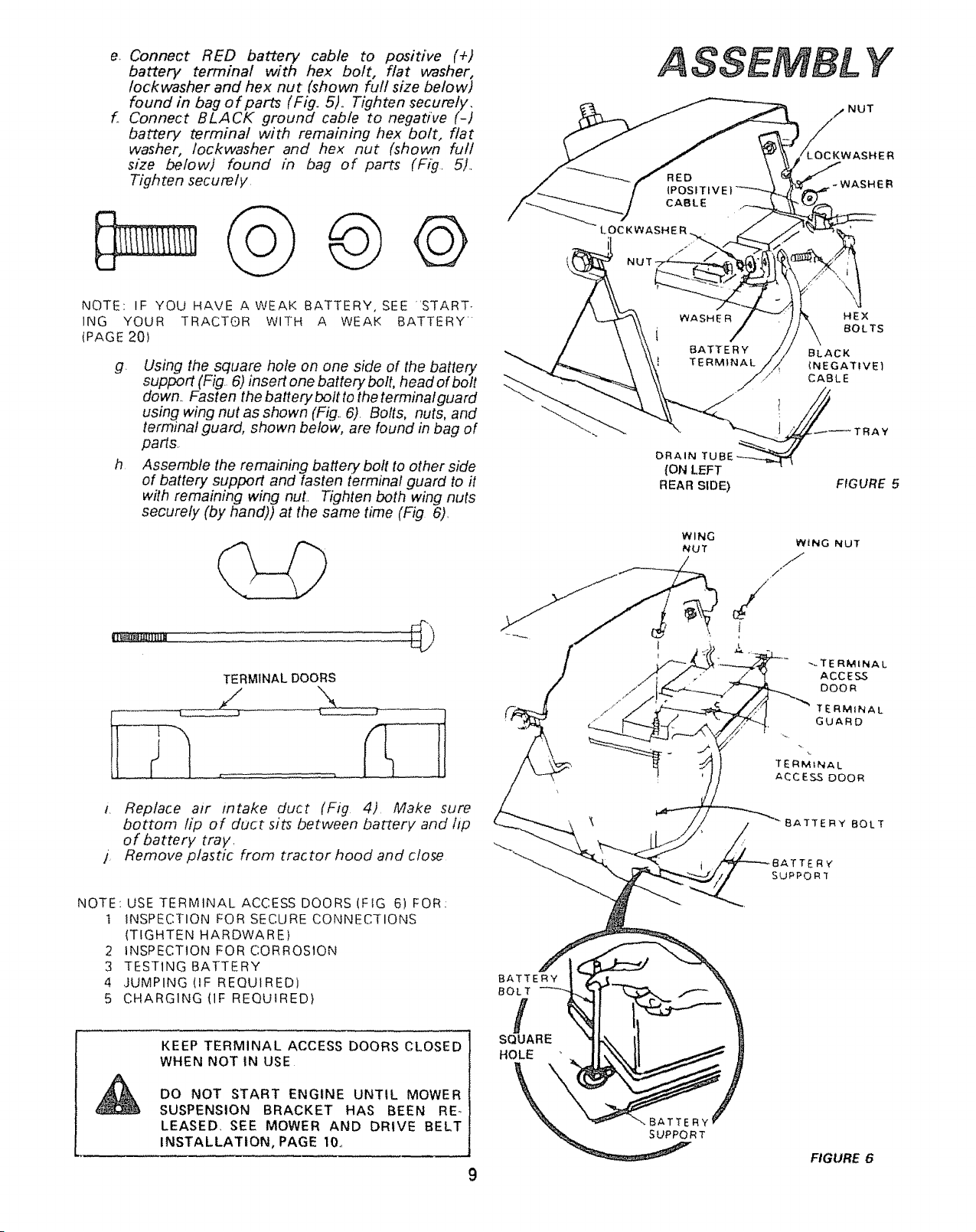
e. Connect RED battery cable to positive (+)
battery terminal with hex bolt, flat washer,
lockwasher and hex nut (shown full size below)
found in bag of parts (Fig. 5).. Tighten securely.
f. Connect BLACK ground cable to negadve (-)
battery terminal with remaining hex bolt, flat
washer, /ockwasher and hex nut (shown furl
size belowj found in bag of parts (Fig. 5)..
Tighten securely.
©©
NOTE IF YOU HAVE A WEAK BATTERY, SEE 'START-
ING YOUR TRACTOR WITH A WEAK BATTERY'
(PAGE 20)
g. Using the square hole on one side of the battery
support (Fig. 6) insert one battery bolt, head of bolt
down.. Fasten the battery bolt to the terminal guard
using wing nut as shown (Fig.. 6). Bolts, nuts, and
terminal guard, shown below, are found in bag of
parts.
h Assemble the remaining battery bolt to other side
of battery support and fasten terminal guard to it
with remaining wing nut.. Tighten both wing nuts
securely (by hand)) at the same time (Fig 6).
TERMINAL DOORS
t. Replace air intake duct (Fig 4). Make sure
bottom lip of duct sits between battery and lip
of battery tray.
j. Remove plastic from tractor hood and close
NOTE: USE TERMINAL ACCESS DOORS(FIG 6) FOR:
1 INSPECTION FOR SECURE CONNECTIONS
(TIGHTEN HARDWARE)
2 INSPECTION FOR CORROSION
3 TESTING BATTERY
4 ,JUMPING (IF REQUIRED)
5 CHARGING(IF REQUIRED)
KEEP TERMINAL ACCESS DOORS CLOSED
WHEN NOT IN USE
DO NOT START ENGINE UNTIL MOWER
SUSPENSION BRACKET HAS BEEN RE-,
LEASED SEE MOWER AND DRIVE BELT
INSTALLATION, PAGE 10,,
BATTERY
BOLT
f
SQUARE
HOLE
WASHE R HEX
i BOLTS
BATTERY BLACK
TERMINAL (NEGATIVE)
_///./ ' CABLE
DRAIN TU
{ON LEFT
REAR SIDE)
FIGURE 5
WING
NUT
WiNG NUT
J
/"
/
TERMfNAL
GUARD
TERMINAL
ACCESS DOOR
FIGURE 6
ASSEMBLY
RETAINER
_ SPRING
/
MOWER
PARALLEL LINK
FIGURE 7
SUS.PE NSION
ARMS
HINGE
LiFT jLtFT
TRUNNION t BRACKET
FIGURE8
ATTACHMENT CLUTCH
SWITCH (C
PosmoN)
REAR HINGE
I_tN' LEVER
PLUNGER
HEIGHT A DJUSTMENT
KNOB
%
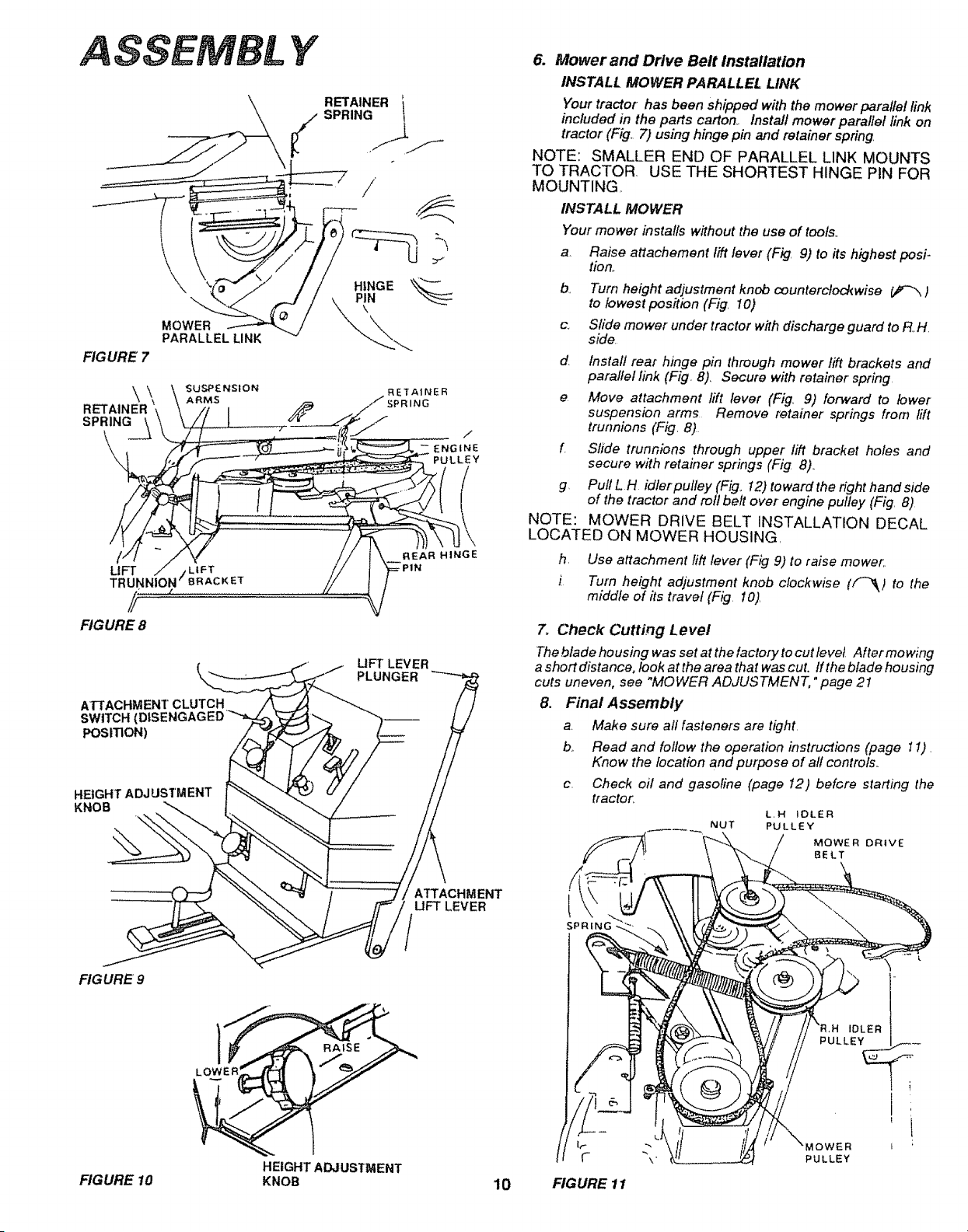
6. Mower and Drive Belt Installation
INSTALL MOWER PARALLEL LINK
Your tractor has been shipped with the mower parallel link
included in the parts carton, Install mower parallel link on
tractor (Fig. 7) using hinge pin and retainer spring,
NOTE: SMALLER END OF PARALLEL LINK MOUNTS
TO TRACTOR USE THE SHORTEST HINGE PIN FOR
MOUNTING,
INSTALL MOWER
Your mower installs without the use of tools..
a, Raise attachement lift lever (Fig, 9) to its highest posi-
tion,.
b,, Turn height adjustment knob counterclockwise _ )
to lowest position (Fig, 10)
c, Slide mower under tractor with discharge guard to R,.H,
side
d Install rear hinge pin through mower flit brackets and
parallel link (Fig. 8), Secure with retainer spring,
e Move attachment lift lever (Fig, 9) forward to lower
suspension arms, Remove retainer springs from fift
trunnions (Fig, 8)
f Slide trunnions through upper lift bracket holes and
secure with retainer springs (Fig 8),
g, Pull L H idter putley (Fig_ 12) toward the right hand side
of the tractor and roll belt over engine pulley (Fig, 8)
NOTE: MOWER DRIVE BELT INSTALLATION DECAL
LOCATED ON MOWER HOUSING,
h. Use attachment lift lever (Fig 9) to raise mower,,
i Turn height adjustment knob clockwise ([_) to the
middle of its travel (Fig 10),
7o Check Cutting Level
The blade housing was set at the factory to cut tevet After mowing
a shortdistance, look atthe area that was cut, Iftheblade housing
cuts uneven, see "MOWER ADJUSTMENT," page 2I
8. Final Assembly
a Make sure all fasteners are tight.
b., Read and follow the operation instructions (page 1I),
Know the location and purpose of all controls,,
c, Check oil and gasoline (page I2) befGre staffing the
tractor,
L.H $OLER
NUT PULLEY
MOWER DRIVE
BELT
ATTACHMENT
UFT LEVER
SPR_NG
FIG URE 9
FIGURE 10
LOWER
HEIGHT ADJUSTMENT
KNOB
10
FIGURE 11
IDLER
PULLEY
i
'i
OWER L ;
PULLEY
OPERATION
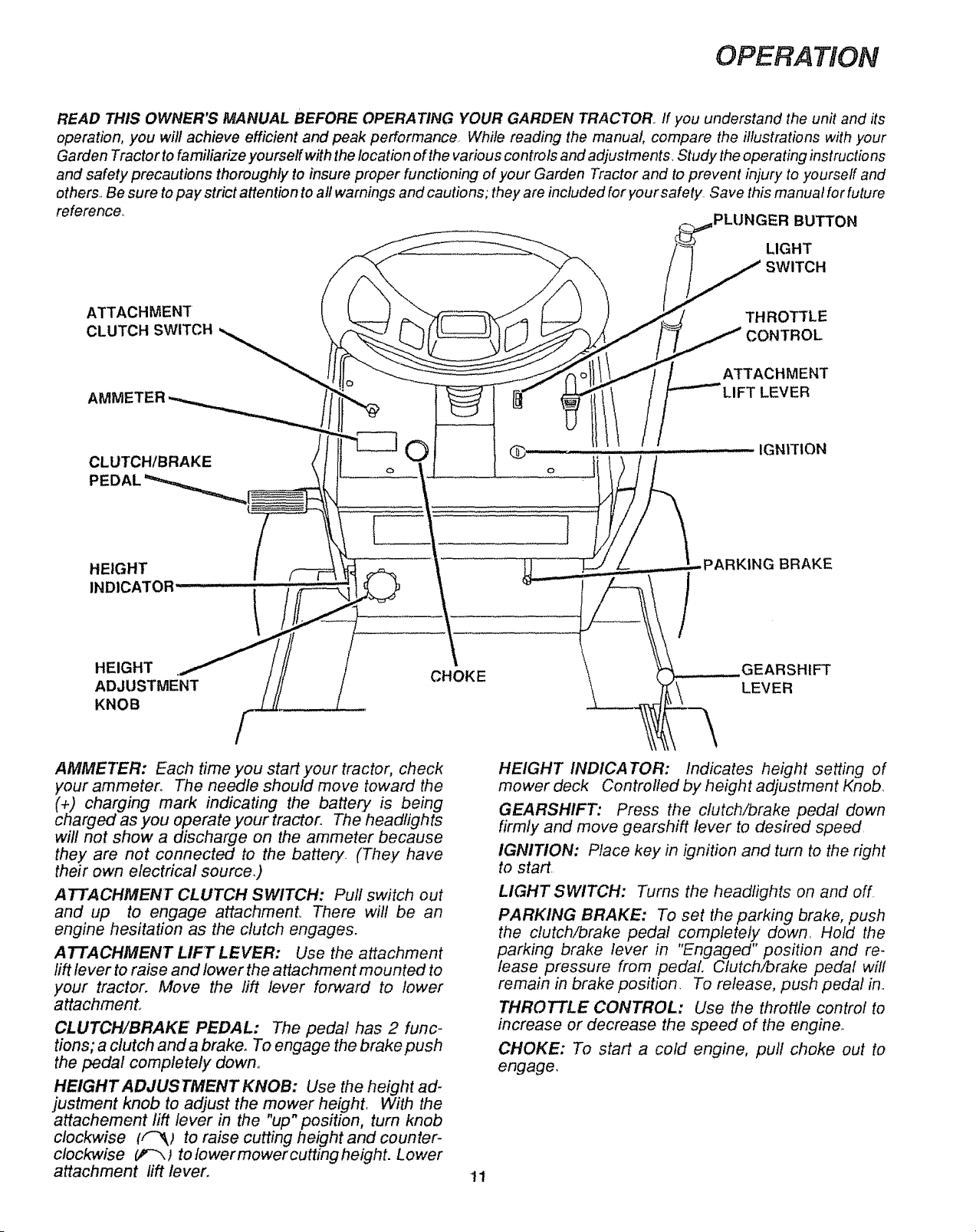
READ THIS OWNER'S MANUAL BEFORE OPERATING YOUR GARDEN TRACTOR.. If you understand the unit and its
operation, you will achieve efficient and peak performance. While reading the manual, compare the illustrations with your
Garden Tractor to familiarize yourself with the location of the various controls and adjustments. Study the operating instructions
and safety precautions thoroughly to insure proper functioning of your Garden Tractor and to prevent injury to yourself and
others.. Be sure to pay strict attention to all warnings and cautions; they are included for your safety Save this manual for future
reference° PLUNGER BUTTON
LIGHT
SWITCH
ATTACHMENT _HRNOTTToLLE
CLUTCH SWITCH
TACHMENT
AMMETER --T LEVER
CLUTCH/BRAKE
PE
HEIGHT
INDICATOR
HEIGHT
ADJUSTMENT
KNOB
CHOKE
IGNITION
AMMETER: Each time you start your tractor, check
your ammeter° The needle should move toward the
(+) charging mark indicating the batte_ is being
charged as you operate your tractor. The headlights
will not show a discharge on the ammeter because
they are not connected to the battery. (They have
their own electrical source,)
ATTACHMENT CLUTCH SWITCH: Pull switch out
and up to engage attachment_. There will be an
engine hesitation as the clutch engages.
ATTACHMENT LIFT LEVER: Use the attachment
lift lever to raise and lower the attachment mounted to
your tractor. Move the lift lever forward to lower
attachment°
CLUTCH!BRAKE PEDAL: The pedal has 2 func-
tions; a clutch and a brake, To engage the brake push
the pedal completely down.
HEIGHT ADJUSTMENT KNOB: Use the height ad-
justment knob to adjust the mower height, With the
attachement lift lever in the "up" position, turn knob
clockwise (f-_; to raise cutting height and counter-
clockwise _-_ ) to lower mower cutting height. Lower
attachment lift lever.
HEIGHT INDICATOR: Indicates height setting of
mower deck Controlled by height adjustment Knob_
GEARSHIFT: Press the ctutch/brake pedal down
firm!y and move gearshift lever to desired speed
IGNITION: Place key in ignition and turn to the right
to start
LIGHT SWITCH: Turns the headlights on and off
PARKING BRAKE: To set the parking brake, push
the clutch/brake pedal completely down, Hold the
parking brake lever in "Engaged" position and re-
lease pressure from pedal Clutch/brake pedal will
remain in brake position, To release, push pedal in..
THROTTLE CONTROL: Use the throttle control to
increase or decrease the speed of the engine.
CHOKE: To start a cold engine, pull choke out to
engage,
11
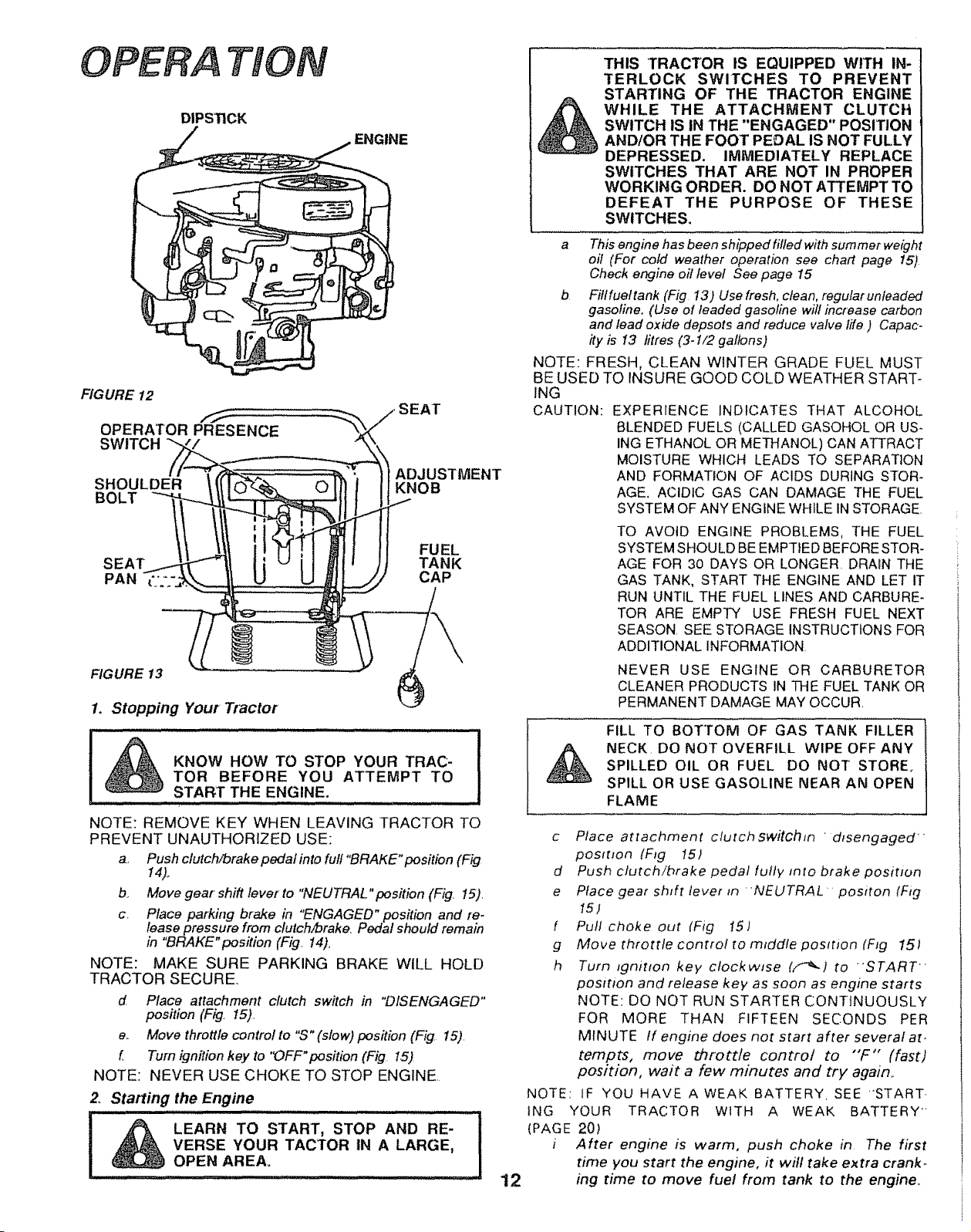
OPERA TION
DIPSTICK
,ENGINE
FIGURE 12
OPERATOR PRESENCE
SWITCH
SHOULDER
BOLT _
_T
ADJUSTMENT
KNOB
I"*
FUEL
TANK
CAP
FIGURE 13
1. Stopping Your Tractor
&
KNOW HOW TO STOP YOUR TRAC-
TOR BEFORE YOU ATTEMPT TO
START THE ENGINE.
NOTE: REMOVE KEY WHEN LEAVING TRACTOR TO
PREVENT UNAUTHORIZED USE:
a. Push clutch/brake pedal into ful!"BRAKE"position (Fig
14).
b,. Move gear shift lever to "NEUTRAL"pos#ion (Fig, 15).
c. Place park#Tg brake in "ENGAGED" position and re-
lease pressure from clutch/brake. Pedal should remain
in "BRAKE "position (Fig. 14).
NOTE: MAKE SURE PARKING BRAKE WILL HOLD
TRACTOR SECURE.
d Place attachment clutch switch in "DISENGAGED"
pos#ion (Fig 15).
e., Move throttle control to "S" (slow) position (Fig. 15).
f Turn ignition key to 'OFF" position (Fig 1.5)
NOTE: NEVER USE CHOKE TO STOP ENGINE.
2. StaRing the Engine
,,UIHIIILUlHUII .........J'"n . Ul JII ','.L!
LEARN TO START, STOP AND RE-
VERSE YOUR TACTOR IN A LARGE,
OPEN AREA_
; Hin H,ll i
12
&
THIS TRACTOR IS EQUIPPED WITH IN-
TERLOCK SWITCHES TO PREVENT
STARTING OF THE TRACTOR ENGINE
WHILE THE ATTACHMENT CLUTCI4
SWITCH IS IN THE "ENGAGED" POSITION
AND/OR THE FOOT PEDAL IS NOT FULLY
DEPRESSED. IMMEDIATELY REPLACE
SWITCHES THAT ARE NOT IN PROPER
WORKING ORDER. DO NOT ATTEMPT TO
DEFEAT THE PURPOSE OF THESE
SWITCHES,
a This engine has been shipped filled with summer weight
oil (For cold weather operation see chart page 15)
Check engine oil level See page 15
b Fittfuettank (Fig 13) Use fresh, clean, regutarunfeaded
gasoline. (Use of leaded gasoline will increase carbon
and lead oxide depsots and reduce valve life ) Capac-
ity is 13 litres (3- I/2 gallons)
NOTE: FRESH, CLEAN WINTER GRADE FUEL MUST
BE USED TO INSURE GOOD COLD WEATHER START-
ING
CAUTION: EXPERIENCE INDICATES THAT ALCOHOL
BLENDED FUELS (CALLED GASOHOL OR US-
ING ETHANOL OR METHANOL) CAN ATTRACT
MOISTURE WHICH LEADS TO SEPARATION
AND FORMATION OF ACIDS DURING STOR-
AGE. ACIDIC GAS CAN DAMAGE THE FUEL
SYSTEM OF ANY ENGINE WHILE iN STORAGE.
TO AVOID ENGINE PROBLEMS, THE FUEL
SYSTEM SHOULD BE EMPTIED BEFORE STOR-
AGE FOR 30 DAYS OR LONGER. DRAIN THE
GAS TANK, START THE ENGINE AND LET IT
RUN UNTIL THE FUEL LINES AND CARBURE_
TOR ARE EMPTY USE FRESH FUEL NEXT
SEASON. SEE STORAGE INSTRUCTIONS FOR
ADDITIONAL INFORMATION.
NEVER USE ENGINE OR CARBURETOR
CLEANER PRODUCTSINTHE FUEL TANK OR
PERMANENT DAMAGE MAY OCCUR.
FILL TO BOTTOM OF GAS TANK FILLER
NECK, DO NOT OVERFILL WIPE OFF ANY
SPILLED OIL OR FUEL DO NOT STORE,
SPILL OR USE GASOLINE NEAR AN OPEN
FLAME
c Place attachment clutchswitchm r dtsengaged
posttlon {Fig 151
d Push c/utch/brake pedal fully _nto brake position
e Place gear shift lever in "NEUTRAL positon (Fig
15)
f Pull choke out (Fig I5)
g Move throttle control to mtddte position (Fig 151
h Turn ignition key ctockwsse (,.'_.} to 'START
position and release key as soon as engine starts
NOTE: DO NOT RUN STARTER CONTINUOUSLY
FOR MORE THAN FIFTEEN SECONDS PER
MINUTE If engine does not start after several at.
tempts, move dTrott/e control to "'F'" (fast)
position, wait a few minutes and try again..
NOTE: IF YOU HAVE A WEAK BATTERY SEE "START.
ING YOUR TRACTOR WITH A WEAK BATTERY ''
(PAGE 20)
i After engine is warm, push choke in The f#st
time you start the engine, it will take extra crank-
mg time to move fuel from tank to the engine,
NOTE: ALLOW ENGINE TO WARM UP FOR A
FEW MINUTES BEFORE ENGAGING CLUTCH OF
TRACTOR OR ATTACHMENT
When restarting a warm engine, move throttle
control midway between "S'" (,slow) and
"F'" (fast) positions Choke may not have
to be used
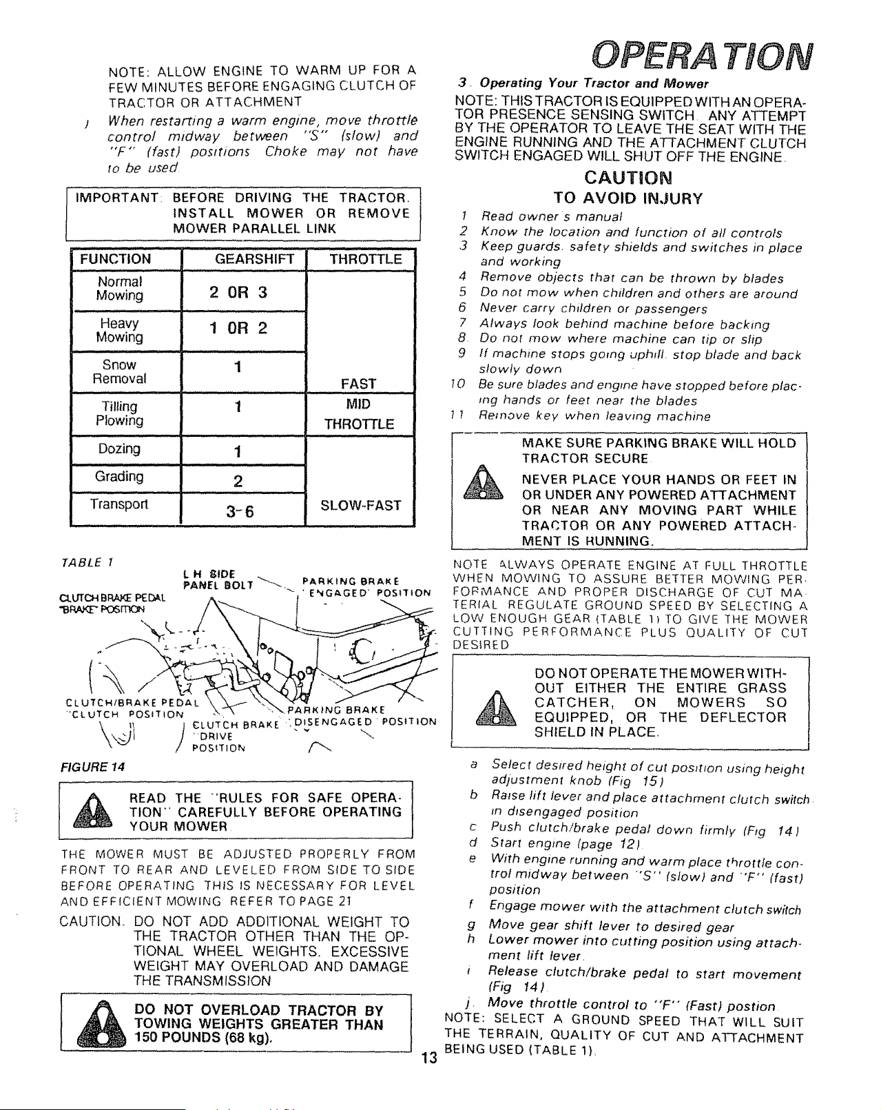
IMPORTANT: BEFORE DRIVING THE TRACTOR,
INSTALL MOWER OR REMOVE
MOWER PARALLEL LINK
GEARSHIFT
FUNCTION
Normal
Mowing 2 OR 3
Heavy 1 OR 2
Mowing
Snow
Removal
Tilling 1
Plowing
Dozing
Grading
Transport
1
i i.i , i. ,i, ,I,IH
1
,...,.,.iJ
2
3-6
FAST
MID
THROTTLE
SLOW-FAST
FIGURE 14
READ THE "°RULES FOR SAFE OPERA-
TION" CAREFULLY BEFORE OPERATING
YOUR MOWER
THE MOWER MUST BE ADJUSTED PROPERLY FROM
FRONT TO REAR AND LEVELED FROM SIDE TO SIDE
BEFORE OPERATING THIS IS NECESSARY FOR LEVEL
AND EFFICIENT MOWING REFER TOPAGE 2]
CAUTION. DO NOT ADD ADDITIONAL WEIGHT TO
THE TRACTOR OTHER THAN THE OP-
TIONAL WHEEL WEIGHTS. EXCESSIVE
WEIGHT MAY OVERLOAD AND DAMAGE
THE TRANSMISSION
DO NOT OVERLOAD TRACTOR BY
TOWING WEIGHTS GREATER THAN
150 POUNDS (68 kg),
13
TION
3. Operating Your Tractor and Mower
NOTE: THIS TRACTOR tS EQUIPPED WITH AN OPERA-
TOR PRESENCE SENSING SWtTCH ANY ATTEMPT
BY THE OPERATOR TO LEAVE THE SEAT WITH THE
ENGINE RUNNING AND THE ATTACHMENT CLUTCH
SWITCH ENGAGED WILL SHUT OFF THE ENGINE,
CAUTION
TO AVOID INJURY
1 Read owner's manual
2 Know the location and function of all controls
,3 Keep guards, safety shields and switches in place
and working
4 Remove objects that can be thrown by blades
5 Do not mow when children and others are around
6 Never carry children or passengers
7 Always look behind machine before backing
8 Do not mow where machine can tip or slip
9 If machine stops going uphill, stop blade and back
slowly down
10 Be sure blades and engine have stopped before plac-
ing hands or feet near the blades
1 I Remove key when leaving machine
MAKE SURE PARKING BRAKE WILL HOLD
TRACTOR SECURE
NEVER PLACE YOUR HANDS OR FEET IN
OR UNDER ANY POWERED ATTACHMENT
OR NEAR ANY MOVING PART WHILE
TRACTOR OR ANY POWERED ATTACH*
MENT IS RUNNING.
NOTE ALWAYS OPERATE ENGINE AT FULL THROTTLE
WHEN MOWING TO ASSURE BETTER MOWING PER.
FORMANCE AND PROPER DISCHARGE OF CUT MA
TERIAL REGULATE GROUND SPEED BY SELECTING A
LOW ENOUGH GEAR (TABLE 1) TO GIVE THE MOWER
CUTTING PERFORMANCE PLUS QUALITY OF CUT
DESIRED
DO NOT OPERATE THE MOWER WITH-
OUT EITHER THE ENTIRE GRASS
CATCHER, ON MOWERS SO
EQUIPPED, OR THE DEFLECTOR
SHIELD IN PLACE..
a Select desired height of cut posmon using height
adjustment knob (Fig 15)
b Raise lift lever and place attachment clutch switch
fn disengaged position
c Push clutch/brake pedal down firmly (Fig !4)
d Start engme (page 12)
e With engine running and warm place throttle con-
trol midway between 'S" (stow) and "'F" (fast)
position
f Engage mower with the attachment clutch switch
g Move gear shift lever to desired gear
h Lower mower into cutting position using attach-
ment lift lever.
i Release c/utch/brake pedal to start movement
(Fig 14)
j. Move throttle control to "F" (Fast) postion
NOTE: SELECT A GROUND SPEED THAT WILL SUIT
THE TERRAIN, QUALITY OF CUT AND ATTACHMENT
BEING USED (TABLE 1).
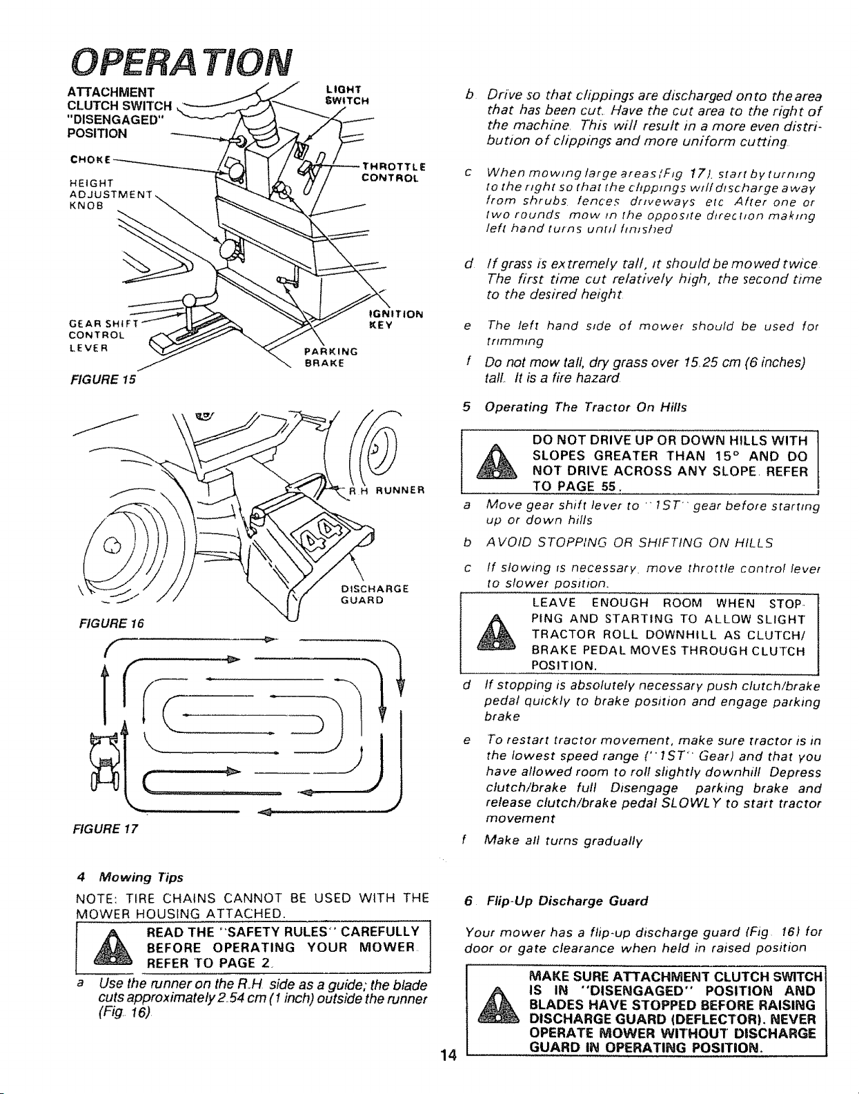
OPERA
ATTACHMENT
CLUTCH SWITCH
"DISENGAGED"
POSITION
HEIGHT
KNOB
TION
LIGHT
SWITCH
3TTLE
CONTROL
b
Drive so that clippings are discharged onto the area
that has been cut. Have the cut area to the right of
the machine. This will result in a more even distri-
bution of chppings and more uniform cutting
When mowing large areas/FIg 17). start by turn_ng
to the right ,so that the chppmgs wHf discharge a way
from shrubs fences driveways etc After one or
two rounds mow _n the opposite direction making
left hand turns until finished
G£AR SHIFT
CONTROL
LEVER
FIGURE t5
PARKING
BRAKE
- R H RUNNER
DISCHARGE
GUARD
FIG URE 16
f
r
FIGURE 17
d Ifgrass is ex tremety tall, it should be mowed twice
The first time cut relatively high, the second time
to the desired height
e The left hand ssde of mower should be used for
trimming
f Do not mow tall, dry grass over 15.25 cm (6 inches)
tall.. It is a fife hazard
5 Operating 'The Tractor On Hills
a
b
C
d
e
DO NOT DRIVE UP OR DOWN HILLS WITH
SLOPES GREATER THAN 15 ° AND DO
NOT DRIVE ACROSS ANY SLOPE. REFER
TO PAGE 55.
Move gear shift lever to _ 1ST'" gear before starting
up or down hills
AVOID STOPPING OR SHIFTING ON HILLS
If slowing _s necessary, move throttle control lever
to slower position.
LEAVE ENOUGH ROOM WHEN STOP..
PING AND STARTING TO ALLOW SLIGHT
TRACTOR ROLL DOWNHILL AS CLUTCH/
BRAKE PEDAL MOVES THROUGH CLUTCH
POSITION,
If stopping is absolutely necessary push clutch/brake
pedal quickly to brake position and engage parking
brake
To restart tractor movement, make sure tractor is in
the lowest speed range ('" 1ST' Gear) and that you
have allowed room to roll slightly downhill Depress
clutch!brake full Disengage parking brake and
release clutch/brake pedal SLOWLY to start tractor
movement
f Make all turns gradually
4 Mowing Tips
NOTE: TIRE CHAINS CANNOT BE USED WITH THE
MOWER HOUSING ATTACHED.
I _ READ THE "SAFETY RULES" CAREFULLY
BEFORE OPERATING YOUR MOWER.
REFER 'TO PAGE 2,
a Use the runner on the R.H side as a guide; the blade
cuts approximately254 cm (1 inch) outside the runner
(Fig. 16)
6 Flip-Up Discharge Guard
Your mower has a flip*up discharge guard (Fig 161 for
door or gate clearance when held in raised position
14
MAKE SURE ATTACHMENT CLUTCH SWITCH
IS IN "DISENGAGED" POSITION AND
BLADES HAVE STOPPED BEFORE RAISING
DISCHARGE GUARD (DEFLECTOR), NEVER
OPERATE P/lOWER WITHOUT DISCHARGE
GUARD IN OPERATING POSITION.
To keep your tractor running better,
longer, perform necessary service using
the following maintenance schedule:
MAINTENANCE
BEFORE MAKING ANY INSPECT!ON AD-
JUSTMENT OR REPAIR:
PUSH TRACTOR CLUTCH BRAKE PEDAL
COMPLETELY INTO BRAKE POSITION
2 MOVE GEAR SHIFT LEVER TO NEU-
TRAL" POSITION
3 PLACE PARKING BRAKE IN ENGAGED
POSITION REMOVE FOOT FROM
PEDAL
4 PLACE ATTACHMENT CLUTCH SWITCH
IN DISENGAGED POS1TION
5 TURN IGNITION KEY TO OFF POSI-
TION
6 MAKE ABSOLUTELY SURE THE BLADES
AND ALL MOVING PARTS HAVE COM-
PLETELY STOPPED
7 REMOVE THE IGNITION KEY
DISCONNECT THE SPARK PLUG WIRES
FROM THE SPARK PLUGS AND KEEP
AWAY FROM THE SPARK PLUGS TO
PREVENT INJURY FROM ACCIDENTAL
STARTING, BE CAREFUL TOO AVOID
TOUCHING HOT ENGINE OR MUFFLER
COMPONENTS
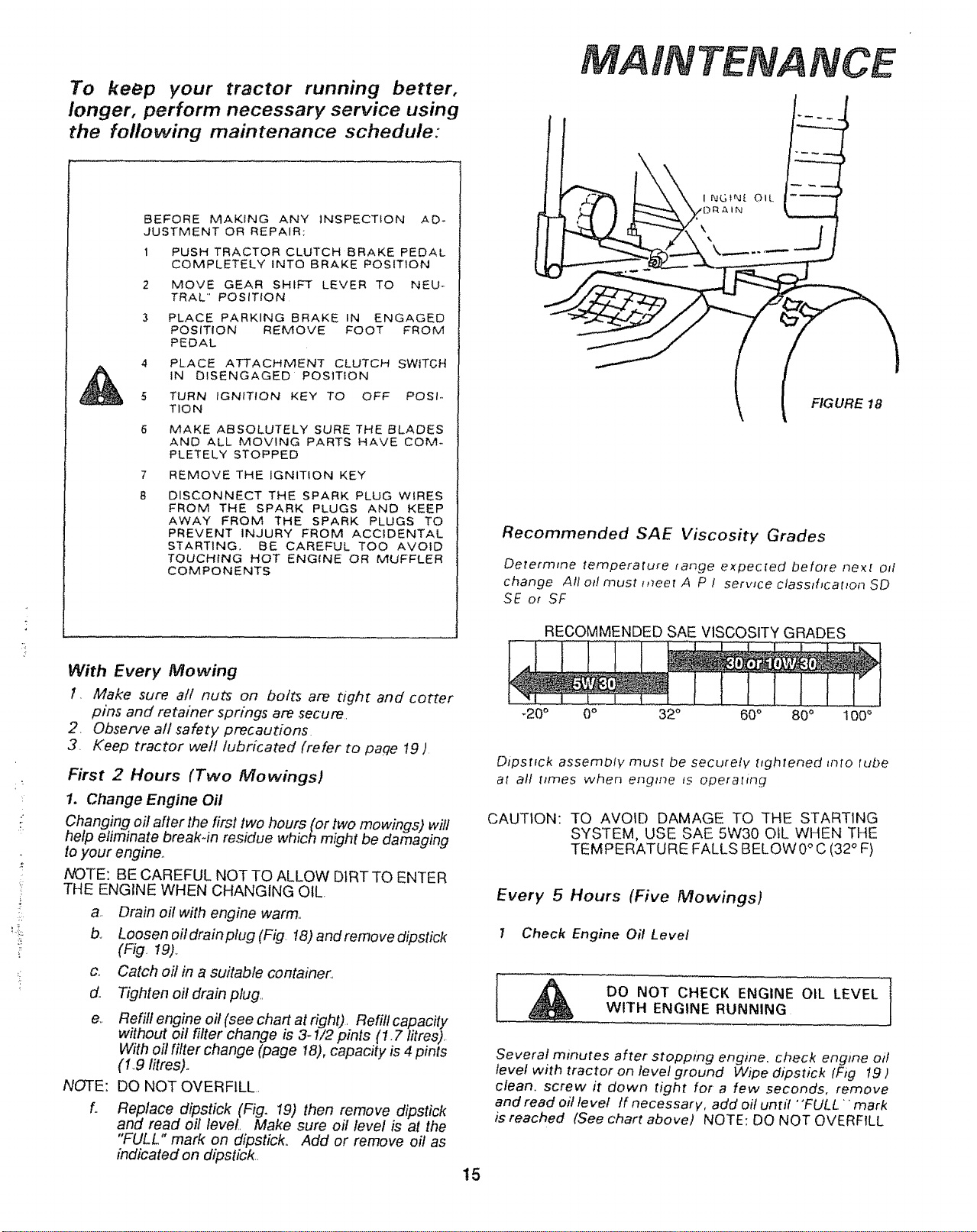
FIGURE 18
Recommended SAE Viscosity Grades
Determme tempera[ure tange expecfed before ne×f od
change All otl must mee! A P ! service ctasmhcat_on SD
SE or SF
RECOMMENDED SAE VISCOSITY GRADES
,t
i'
With Every Mowing
I, Make sure all nuts on bolts are tight and cotter
pins and retafner springs are secure.
2, Observe all safety precautions
3. Keep tractor well lubricated (refer to paqe 19 )
First 2 Hours (Two Mowings)
1. Change Engine Oil
Changing oil after the first two hours (or two mowings) will
help eliminate breakqn residue which might be damaging
to your engine.,
NOTE: BE CAREFUL NOT TO ALLOW DLRTTO ENTER
THE ENGINE WHEN CHANGING OIL.
a, Drain oil with engine warm,,
b., Loosen ofldrainplug (Fig !8) andremovedipstick
(F_g, 19).,
c,, Catch oil in a suitable container.,
d.
e,.
NOTE:
L
Tighten oi! drain plug,,
Refill engine oil (see chart at right), Refill capacity
without oil filter change is 3-1/2 pints (1.7 litres),
With oil filter change (page 18), capacity is 4 pints
(19 titres)_
DO NOT OVERFILL,
Replace dipstick (Fig. 19) then remove dipstick
and read oil level,, Make sure oil level is at the
"FULL" mark on dipstick,, Add or remove oil as
indicated on dipstick,,
-20 ° 0° 32 ° 60 ° 80 ° 100 °
Dipsttck assembly mus[ be securely nghtened mid lube
at all t_mes when engine is operalrng
CAUTION: TO AVOID DAMAGE TO THE STARTING
SYSTEM, USE SAE 5W30 OIL WHEN THE
W °
TEMPERATURE FALLS BELO 0 C(32"F)
Every 5 Hours (Five Mowings}
I Check Engine Oil Level
!
DO NOT CHECK ENGINE OIL LEVEL |
WITH ENGINE RUNNING
Several minutes after stopping engine, check engine oil
level with tractor on level ground Wipe dipstick tFJ# 19)
clean, screw it down tight for a few seconds, remove
and read oil level If necessary, add oil until "FULL" mark
is reached (See chart above) NOTE: DO NOT OVERFILL
15
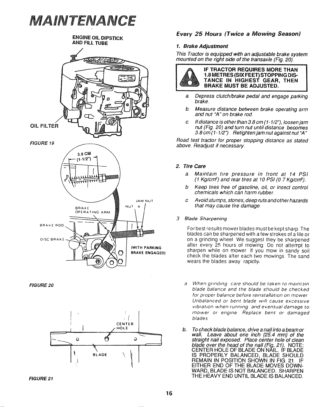
MA
OIL FILTER
FIG URE 19
BRAKE
OISC BR_,K e
TENANCE
ENGINE OIL DIPSTICK
AND FILL TUBE
(WITH PARKING
BRAKE ENGAGED)
Every 25 Hours (Twice a Mowing Season)
1. Brake Adjustment
This Tractor is equipped with an adjustable brake system
mounted on the right side of the transax/e (Fig.. 20)_
!A
IF TRACTOR REQUIRES MORE THAN
1.8 METRES (SIX FEET) STOPPING DIS-
TANCE IN HIGHEST GEAR, THEN
BRAKE MUST BE ADJUSTED.
a. Depress clutch/brake pedal and engage parking
brake._
b. Measure distance between brake operating arm
and nut "A" on brake rod..
c If distance is other than 3.8 cm (1-1/2"), loosen jam
nut (Fig.. 20) and turn nut until distance becomes
3..8cm (1- I/2"). Retighten jam nut against nut ",4"
Road test tractor for proper stopping distance as stated
above._ Readjust ff necessary..
2. Tire Care
a. Maintain tire pressure in front at 14 PSI
(1 Kg/cnf) and rear tires at 10 PSI (0.7 Kg/cnf)..
b Keep tires free of gasoline, oil, or insect control
chemicals which can harm rubber.
c Avoidstumps, stones, deep rutsandother hazards
that may cause tire damage.
3 Blade Sharpening
For best results mower blades must be kepl sharp. The
blades can be sharpened with a few strokes of a tile or
on a grinding wheel We suggest they be sharpened
after every 25 hours oi mowing Do not attempt to
sharpen while on mower fl you mow in sandy soil
check the bfades after each two mowings The sand
wears lhe blades away rapidly,
FIGURE 20
FIGURE 21
,t
\
BLADE
a
When gr_ndmg care should be taken to matntain
blade balance and the blade should be checked
for proper balance before retnstattanon on mower
Unbalanced or bent blade wilt cause excessive
vtbrat_on when running and eventual damage to
mower or engine Replace bent or damaged
blades
b,.
To check blade balance, drive a nail into a beam or
waiL Leave about one inch (25_4 mm) of the
straight nail exposed. Place center hole of clean
blade over the head of the nail (Fig. 21). NOTE:
CENTER HOLE OF BLADE ON NATL. IF BLADE
1S PROPERLY BALANCED, BLADE SHOULD
REMAIN IN POSITION SHOWN IN FIG. 21_ IF
EITHER END OF THE BLADE MOVES DOWN-
WARD, BLADE IS NOT BALANCED. SHARPEN
THE HEAVY END UNTIL BLADE IS BALANCED
16
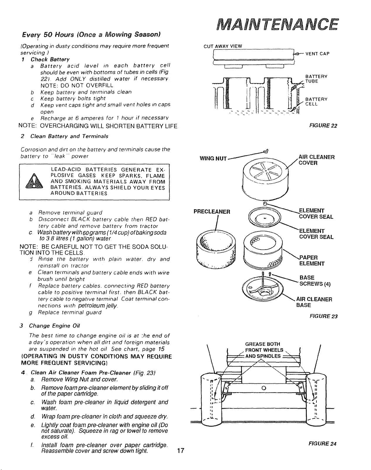
Every 50 Hours (Once a Mowing Season)
e
NOTE:
[Operating in dusty conditions may require more frequent
servicing,)
t Check Battery
a Battery acid level _n each battery cell
should be even with bottoms of tubes in cells (Fig
22) Add ONLY distilled water if necessary
NOTE: DO NOT OVERFILL
b Keep battery and terminals clean
c Keep battery bolts tight
d Keep vent caps tight and small vent holes _n caps
open
Recharge at 6 amperes for t hour if necessary
OVERCHARGING WILL SHORTEN BATTERY LIFE
2 Clean Battery and Terminals
Corrosion and dirt on _he battery and terminals cause the
battery to 'leak power
LEAD-ACID BATTERIES GENERATE EX-
PLOSIVE GASES KEEP SPARKS. FLAME
AND SMOKING MATERIALS AWAY FROM
BATTERIES ALWAYS SHIELD YOUR EYES
AROUND BATTERIES
MAINTENANCE
CUT AWAY VIEW
VENT CAP
_ BA_-FE RY
FIGURE 22
AIR CLEANER
WING NUT ,_-_
a Remove terminal guard
b Disconnect BLACK battery cable then RED bat-
tery cable and remove batterv from tractor
c Wash battery with 60grams (1/4 cup) ofbakingsoda
to 3.8 litres (1 gallon) water
NOTE: BE CAREFUL NOT TO GET THE SODA SOLU-
TION INTO THE CELLS,
:J Rinse the battery w_th plain water, dry and
reinstall on tractor
e Clean terminals and battery cable ends with wire
brush until bright
f Replace battery cables, connectin 9 RED battery
cable to positive terminal first, then BLACK bat-
tery cable to negative terminal Coat terminal con-
nec[ions with petroleumjelfy.
g Replace terminal guard
3 Change Engine Oil
The best time to change engine oi! is at :he end of
a day's operation when all dirt and foreign materials
are suspended in the hot oil See chart, page 15
(OPERATING IN DUSTY CONDITIONS MAY REQUIRE
MORE FREQUENT SERVlClNG)
4, Clean Air Cleaner Foam Pre-Cleaner (Fig, 23 j,
a. Remove Wing Nut and cover°
b, Remove foam pre-cleaner element by sliding # off
of the paper cartridge.
Wash foam pre-cleaner in liquid detergent and
water.,
C,,
d
e.
Wrap foam pre-cleaner in cloth and squeeze dry.,
Lightly coat foam pre.cleaner with engine oil (Do
not saturate). Squeeze in rag or towel to remove
excess oil
Install foam pre-cleaner over paper cartridge
Reassemble cover and screw down tight,,
PRECLEANER ELEMENT
COVER SEAL
17
GREASE BOTH
• FRONT WHEELS
SPINDLES
O
VIENT
COVER SEAL
ELEMENT
BASE
FIG URE 23
FIGURE 24
TENANCE
AIR SCREEN
TOP AIR
COVE R
FIGURE 25
.03O"(.762 MM)
FEELER GUAGE
FIGURE 26
SPARK
PLUG
HOSE CL
HOSE
AMP
FUEL
FIGURE 27
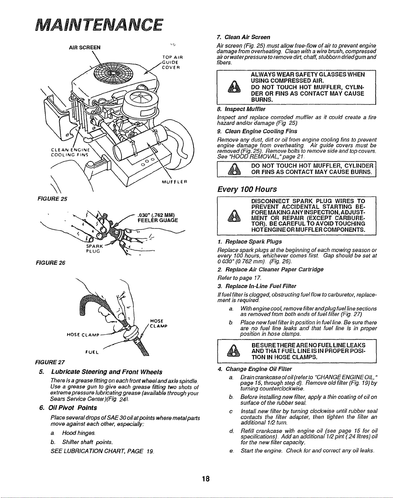
5. Lubricate Steering and Front Wheels
There is a grease fitting on each front wheel and axle spindle.
Use a grease gun to give each grease fitting two shots of
extreme pressure lubricating grease (available through your
Sears Service Center)(Fig 24 [
6. Oil Pivot Points
Place several drops of SAE 30 off at points where metal parts
move against each other, especially:
a Hood hinges..
b_ Shifter shaft points.
SEE LUBRICATION CHART, PAGE 19.
7. Clean Air Screen
Air screen (Fig. 25) must allow free-flow of air to prevent engine
damage from overheating, Clean with a wire brush, compressed
ai/ orwaterpressure to remove dirt, chaff, stubborn dried gum and
fibers._
ALWAYS WEAR SAFETY GLASSES WHEN
USING COMPRESSED AIR.
DO NOT TOUCH HOT MUFFLER, CYLIN-
DER OR FINS AS CONTACT MAY CAUSE
BURNS.
8. Inspect Muffler
Inspect and replace corroded muffler as it could create a fire
hazard and/or damage (Fig 25)
9o Clean Engine Cooling Fins
Remove any dust, dirt or oil from engine cooling fins to prevent
engine damage from overheating. Air guide covers must be
removed(Fig, 25). Remove bolts to remove side and top covers_
See HOOD REMOVAL, page 21.
[ _ DO NOT TOUCH HOT MUFFLER, CYLINDER [OR FINS AS CONTACT MAY CAUSE BURNS_
Every 100 Hours
DISCONNECT SPARK PLUG WIRES TO
PREVENT ACCIDENTAL STARTING BE-
FORE MAKING ANY INSPECTION, ADJUST-
MENT OR REPAIR (EXCEPT CARBURE-
TOR). BE CAREFUL TO AVOID TOUCHING
HOT ENGINE OR MUFFLER COMPONENTS.
1o Replace Spark Plugs
Replace spark plugs at the beginning of each mowing season or
every 100 hours, whichever comes first. Gap should be set at
0 030" (0. 762 mm). (Fig, 26)..
Z Replace Air Cleaner Paper Cartridge
Refer to page 17o
3o Replace In-Line Fuel Filter
if fuel filter is clogged, obstructing fuel flow to carburetor; replace-
ment is required,.
a.. With engine cool, remove filter andplug fuelfine sections
as removed from both ends of fuel filter (Fig_ 27).
b. Place new fuel filter in position in fuel fine.. Be sure there
are no fuel line leaks and that fuel line is in proper
position in hose clamps..
BESURETHERE ARENO FUELLINE LEAKS
AND THAT FUEL LINE iS IN PROPER POSI-
TION IN HOSE CLAMPS.
4. Change Engine Oil Filter
a_ Drain crankcase of oil (refer to "CHANGE ENGINE OIL,"
page 15, through step d)_ Remove old filter (Fig. 19) by
turning counterclockwise°
b_ Before installing new filter, apply a thin coating of oil on
surface of the rubber seal
c Install new filter by turning clockwise until rubber seal
contacts the filter adapter, then tighten the filter an
additional 1/2 tum_
do Refill crankcase with engine o# (see page 15 for oil
specifications). Add an additional 1/2 pint (24 litres) oil
for the new filter capacity°
e. Start the engine.. Check for and correct any oil leaks..
18
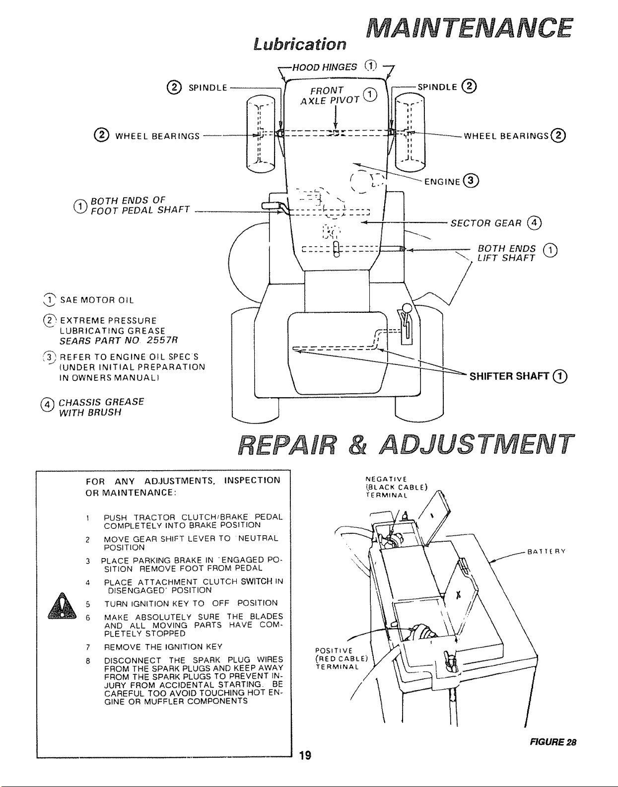
Lubrication
MA
TENANCE
G SPINDLE
O WHEEL BEARINGS
(_ BOTH ENDS OF
FOOT PEDAL SHAFT
_SAEMOTOR OIL
) ×TREME PRESSURE
LUBRICATING GREASE
SEARS PART NO 2557R
_,_j REFER ENGINE OIL SPECS
TO
(UNDER INITIAL PREPARATION
IN OWNERS MANUAL)
(_ CHASSIS GREASE
WITH BRUSH
REPAIR & ADJUSTMENT
FOR ANY ADJUSTMENTS, INSPECTION
OR MAINTENANCE:
I PUSH TRACTOR CLUTCHIBRAKE PEDAL
COMPLETELY INTO BRAKE POSITION
2 MOVE GEAR SHIFT LEVER TO NEUTRAL
POSITION
3 PLACE PARKING BRAKE IN ENGAGED PO-
SITION REMOVE FOOT FROM PEDAL
4 PLACE ATTACHMENT CLUTCH SWITCH IN
DISENGAGED" POSITION
5 TURN IGNITION KEY TO OFF POSITION
6 MAKE ABSOLUTELY SURE THE BLADES
AND ALL MOVING PARTS HAVE COM-
PLETELY STOPPED
7 REMOVE THE IGNITION KEY
8 DISCONNECT THE SPARK PLUG WIRES
FROM THE SPARK PLUGS AND KEEP AWAY
FROM THE SPARK PLUGS TO PREVENT IN-
JURY FROM ACCIDENTAL STARTING, BE
CAREFUL TOO AVOID TOUCHtNG HOT EN-
GINE OR MUFFLER COMPONENTS
_OSITtvE
(RED CABLE)
TERMINAL
19
NEGATIVE
_BLACK CABLE}
TERMINAL
FIGURE 28
REPAIR ADJUS
T$
LEAD-ACID BATTERIES GENERATE
EXPLOSIVE GASES. KEEP SPARKS,
FLAME AND SMOKING MATERIALS
AWAY FROM BATTERIES. ALWAYS
WEAR EYE PROTECTION WHEN
AROUND BATTERIES.
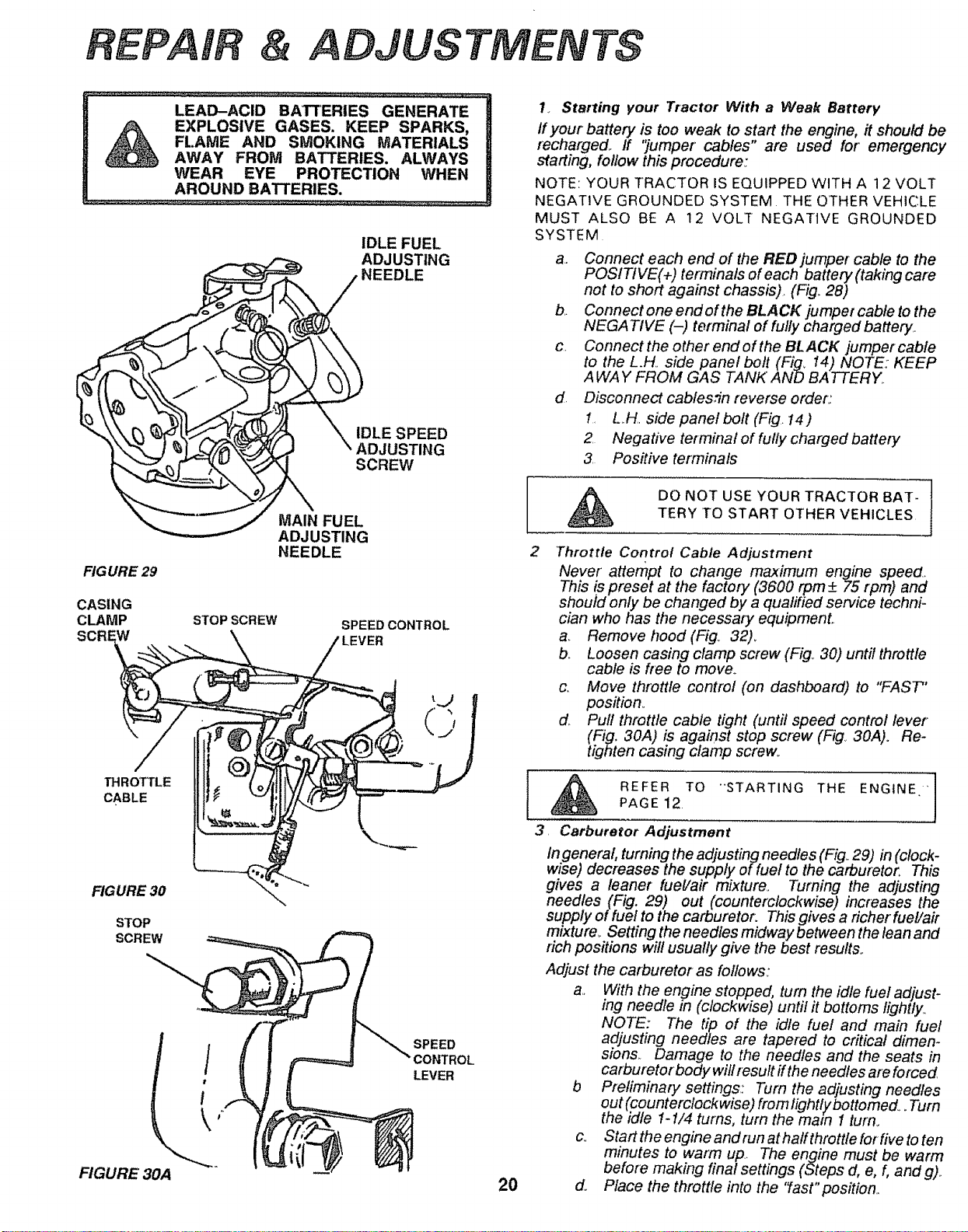
IDLE FUEL
ADJUSTING
NEEDLE
IDLE SPEED
ADJUSTING
SCREW
FIGURE 29
CASING
CLAMP
SCREW
MAIN FUEL
ADJUSTING
NEEDLE
STOP SCREW
SPEED CONTROL
THROllLE
CABLE
FIGURE 30
STOP
SCREW
FIGURE 30A
SPEED
LEVER
2
2O
1_ Starling your Tractor With a Weak Battery
If your battery is too weak to start the engine, it should be
recharged.. If '_umper cables" are used for" emergency
starting, follow this procedure.:
NOTE: YOUR TRACTOR IS EQUIPPED WITH A 12 VOLT
NEGATIVE GROUNDED SYSTEM THE OTHER VEHICLE
MUST ALSO BE A t2 VOLT NEGATIVE GROUNDED
SYSTEM
a. Connect each end of the RED jumper cable to the
POSITIVE(+) terminals of each battery (taking care
not to short against chassis). (Fig.. 28)
b Connect one endof the BLACK jumper cable to the
NEGATIVE (-) terminal of fully charged battery..
c Connectthe other endofthe BLACK jumpercable
to the L.H. side panel bolt(Fig, 14) NOTE: KEEP
AWAY FROM GAS TANK' AND BATTERY..
d. Disconnect cablesfin reverse order:
1. L../-/. side panel bolt (Fig I4)
2 Negative terminal of fully charged battery
3. Positive terminals
DO NOT USE YOUR TRACTOR BAT-
TERY TO START OTHER VEHICLES
Throttle Control Cable Adjustment
Never" attempt to change maximum engine speed._
This !s preset at the factory (3600 rpm +_75 [pm) and
should only be changed by a qualified service techni-
cian who has the necessary equipmenL
a.. Remove hood (Fig, 32)_
b._ Loosen casing clamp screw (Fig,. 30) until throttle
cable is free to move.
c, Move throttle control (on dashboard) to "FAST"
position_
d._ Pull throttle cable tight (until speed control lever
(Fig. 30A) is against stop screw (Fig., 30A). Re-
tighten casing clamp screw,.
REFER TO "'STARTING THE ENGtNE 'II]
PAGE 12
3, Carburetor Adjustment
In generat, turning the adjusting needles (Fig_29) in (clock-
wise) decreases the supply of fuel to the carburetor_ This
gives a leaner fuel/air mixture, Turning the adjusting
needles (Fig. 29) out (counterclockwise) increases the
supply of fuel to the carburetor. This gives a richer fuel/air
mixture_ Setting the needles midway between the lean and
rich positions will usually give the best results,,
Adjust the carburetor as follows;
a.. With the en_Tinestopped, turn the idle fuel adjust-
ing needle m (clockwise) until it bottoms lightly.,
NOTE: The tip of the idle fuel and main fuel
adjusting needles are tapered to critical dimen-
sions_ Damage to the needles and the seats in
carburetorbody will result ff the needles are forced
b Preliminary settings.: Turn the adjusting needles
out (counterclockwise) from lightlybottomed_ .Turn
the idle 1-1/4 turns, turn the matn i turn.
c,. StartttTeengineandrunathalfthrottleforfivetoten
minutes to warm up.. The engine must be warm
before making final settings (Steps d, e, f, and g),.
d, Place the throttle into the 'last"position.,
eJ
1.,Turn the main fuel adjusting needle out (counter-
clockwise) from the prefiminary setting until the
engine speed decreases (rich).
2,.Now turn the adjusting needle in (clockwise),,
The engine speed may increase, then it will
decrease as the needle is turned in (lean),
3.,Now set the adjusting needle midway between
the rich and lean settings,,
Idle Speed Settin_g": Place the throttle control into
the "idle"or "slow 'position° Set the iclle speed to
1200 rpm adjusting screw in or out.,
Idle Fuel Needle Setting: Place the throttle into the
"idle" or "slow" position.
1_.Tum the idle fuel adjusting needle out (counter-
clockwise) from the prefiminary setting until the
engine speed decreases (rich),
2,,Now tum the adjusting needle in (clockwise).
The engine speed may increase, then it will
decrease as the needle is turned in (lean).,
3,,Set the adjusting needle midway between the
rich and lean settings,,
4, Recheck the idle speed. Readjust the speed as
necessary,,
4, Fuse Replacement
Repface with 3O amp automotive4ype plug in fuse Fuses can be
purchased at all Sears Service Centers and most retail stores.
Fuse is located directly behind dash.
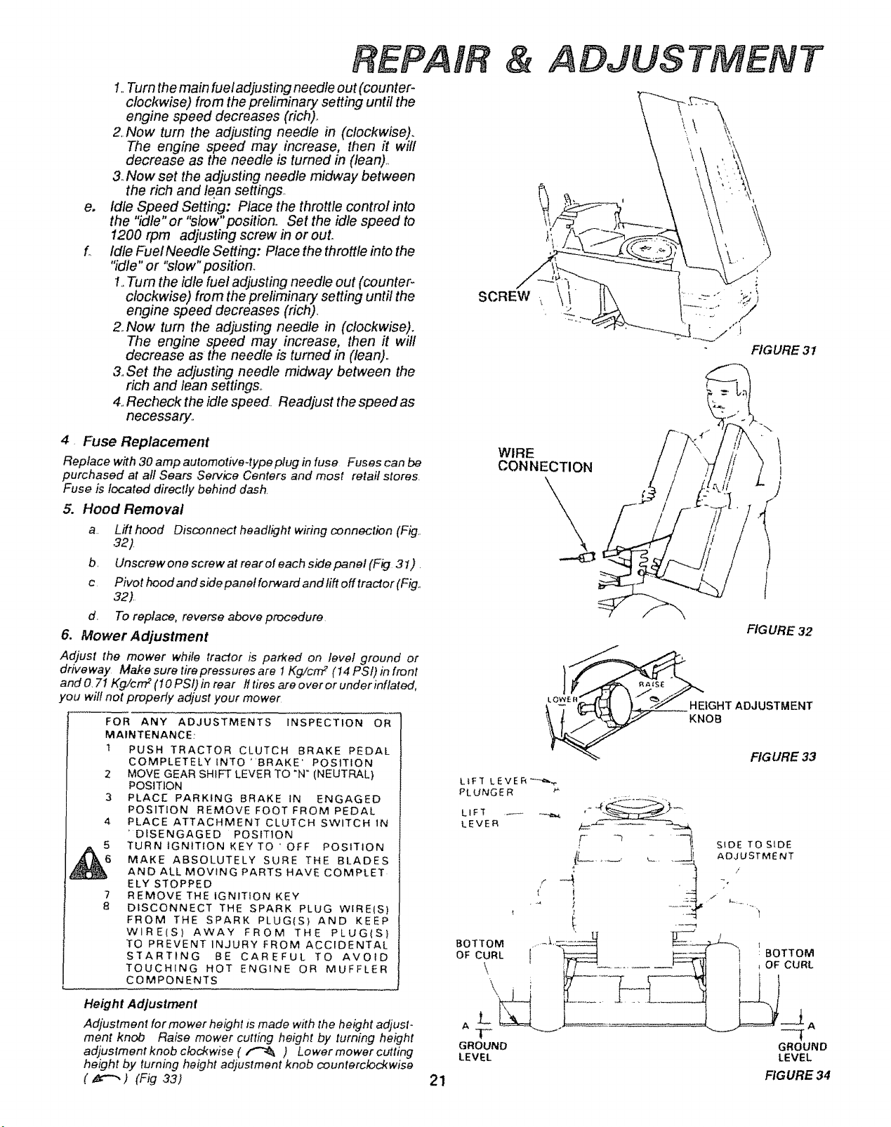
5. Hood Removal
a. Lift hood Disconnect headlight wiring connection (Fig,.
32).
b, Unscrew one screw at rear of each side panel (Fig 31) ,
c Pivothoodandsidepanefforwardandliftofftractor(Fig,,
32)
d, To replace, reverse above procedure
6. Mower Adjustment
Adjust the mower while tractor is parked on level ground or
driveway Make sure tire pressures are I Kg!cm 2 (I4 PSI) in front
and O.7I Kg/cn'P (I0 PSI) in rear ff tires are o vet or under inflated,
you wilt not properly adjust your mower
FOR ANY ADJUSTMENTS INSPECTION OR
MAINTENANCE:
t PUSH TRACTOR CLUTCH BRAKE PEDAL
COMPLETELY INTO "BRAKE' POSITION
2 MOVE GEAR SHIFT LEVER TO "N" (NEUTRAL)
POSITION
3 PLACE PARKING BRAKE 1N ENGAGED
POSITION REMOVE FOOT FROM PEDAL
4, PLACE ATTACHMENT CLUTCH SWITCH 1N
'DISENGAGED POSIT1ON
5 TURN IGNITION KEY TO ' OFF POSITION
6 MAKE ABSOLUTELY SURE THE BLADES
AND ALL MOVING PARTSHAVE COMPLET
ELY STOPPED
7 REMOVE THE IGNITION KEY
8 DISCONNECT THE SPARK PLUG WIRE(S)
FROM THE SPARK PLUG(S) AND KEEP
WIRE(S) AWAY FROM THE PLUG(S}
TO PREVENT INJURY FROM ACCIDENTAL
STARTING BE CAREFUL TO AVOID
TOUCHING HOT ENGINE OR MUFFLER
COMPONENTS
Height Adjustment
Adjustment for mower height ts made with the height adjust-
ment knob Raise mower cutting height by turning height
adjustment knob clockwise ( _ ) Lower mower cutting
height by turning height adjustment knob counterclockwise
(_) (Fig 33)
& ADJUSTMENT
\
SCREW
/
:. ,k
/
.=.
FIGURE 31
WIRE
CONNECTION
L
FIG URE 32
HEIGHT ADJUSTMENT
KNOB
21
FIGURE 33
LIFT L E V E R "-"-_
PLUNGER
LIF]' _
LEVER
SIDE TO SIDE
ADJUSTMENT
i
GROUND GROUND
LEVEL LEVEL
FIGURE 34
REPAIR
ADJUSTMENT
FIGURE" 35
SiDE TO.SiDE
AOJUSTMENT
TRUNNION
II II IIII
C
iiii _
' BOTTOM
OF CURL _._
D
GROUND J-i--
LEVEL
FIGURE 36
D
G ROUND-_"T"
LEVEL
FIGURE 37
ATTACHMENT CLUTCH
SWITCH (
POSITION)
LIFT LEVER
PLUNGER
HEIGHT ADJ USTMENT
KNOB
BOTTOM
OF CURL
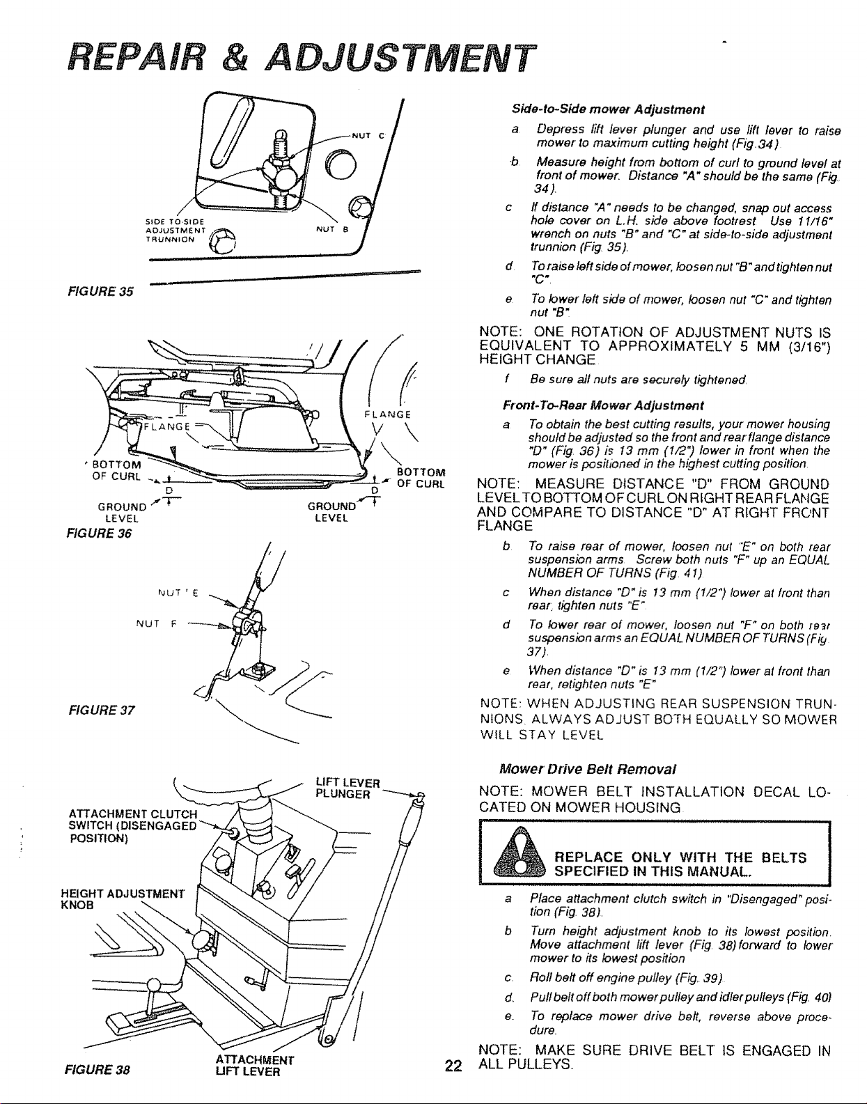
Side.to-Side mower Adjustment
a Depress lift lever plunger and use lift lever to raise
mower to maximum cutting height (Fig34)
b Measure height from bottom of curl to ground level at
front of mower_ Distance "A" should be the same (Fig.
34).
c ff distance ",4" needs to be changed, snap out access
hole cover on LH. side above footrest Use 11/16"
wrench on nuts "B" and "C" at side-to-side adjustment
trunnion (Fig. 35).
To raise left side of mower, loosen nut "B" and tighten nut
"C',
d
e
To lower left side of mower, loosen nut "C" and tighten
nut "B"
NOTE: ONE ROTATION OF ADJUSTMENT NUTS IS
EQUIVALENT TO APPROXIMATELY 5 MM (3/16")
HEIGHT CHANGE
f Be sure all nuts are securefy tightened
Front.To-Rear Mower Adjustment
a To obtain the best cutting results, your mower housing
should be adjusted so the front and rear flange distance
"[9" (Fig 36) is 13 mm (1/2") lower in front when the
mower is posihbned in the highest cutting position.
NOTE: MEASURE DISTANCE "D" FROM GROUND
LEVELTO BOTTOM OFCURL ON RIGHT REAR FLANGE
AND COMPARE TO DISTANCE "D" AT RIGHT FRONT
FLANGE
b To raise rear of mower, loosen nut "E" on both rear
suspension arms Screw both nuts "F" up an EQUAL
NUMBER OF TURNS (Fig 41)
c When distance "[3" is I3 mm (t/2") lower at front than
rear. tighten nuts "E"
d To lower rear of mower; loosen nut "F _ on both [e_t
suspension arms an EQUAL NUMBER OF TURNS (F i#
37).
e When distance "D" is I3 mm (1/2 "_)lower at front than
rear, retighten nuts "E"
NOTE: WHEN ADJUSTING REAR SUSPENSION TRUN-
NIONS ALWAYS ADJUST BOTH EQUALLY SO MOWER
WtLL STAY LEVEL
Mower Drive Belt Removal
NOTE: MOWER BELT INSTALLATION DECAL LO-
CATED ON MOWER HOUSING
REPLACE ONLY WITH THE BELTS
SPECIFIED IN THIS MANUAL.
............... i,,, i i ii i u
a Place attachment clutch switch in "Disengaged" posi.
tion (Fig. 38)
b Turn height adjustment knob to its lowest position.
Move attachment lift lever (Fig 38)forward to lower
mower to its lowest position
c. Rofl belt off engine pulley (Fig.. 39)
d. Pulfbeftoffboth mowerputley andidlerpulleys (Fig. 40)
e. To replace mower drive belt, reverse above proce-
dure
NOTE: MAKE SURE DRIVE BELT tS ENGAGED IN
ATTACHMENT 22 ALL PULLEYS,,
FIGURE 38 UFT LEVER
REPAIR & ADJUSTMENT
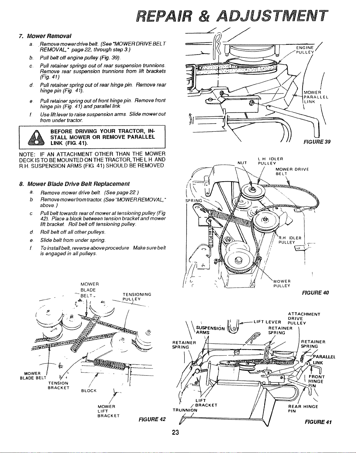
7. Mower Removal
a_ .Remove mower drive belt., (See "MOWER DRIVE BEL T
REMOVAL" page 22, through step 3.)
b.. Pull belt off engine pulley (Fig.. 39).
c, Pull retainer springs out of rear suspension trunnions.
Remove rear suspension trunnions from lift brackets
(Fig 41)
d. Pull retainer spring out of rear hinge pine Remove rear
hinge pin (Fig. 4 !).
e Puff retainer spring out of front hinge pin, Remove front
hinge pin (Fig. 41) and parallel link.
f Use lift lever to raise suspension arms. Sfide mower out
from under tractor.
A BEFORE DRIVING YOUR TRACTOR, IN-
STALL MOWER OR REMOVE PARALLEL
LINK (FIG, 41).
NOTE: IF AN ATTACHMENT OTHER THAN THE MOWER
DECK IS TO BE MOUNTED ON THE TRACTOR, THE L H. AND
R.H. SUSPENSION ARMS (FIG. 41) SHOULD BE REMOVED
&
Mower Blade Drive Belt Replacement
a. Remove mower drive belt (See page 22)
b Removemowerfromtractor. (See'MOWERREMOVAL,"
above. )
c Pullbeft towards rearofmowerat tensioningpulfey (Fig
42_. Place a block between tension bracket and mower
lift bracket. Roll belt off tensioning pulley,
d. Roll belt off all other pulleys.,
e. Sfide belt from under spring.,
f Toinstallbelt, reverseaboveprocedure Makesurebeft
is engaged in all pulleys,
MOWER
BLADE
BELT
TENSIONING
/
/f!
t
SPRING
NUT
L H IDLER
PULLEY
MOWER DRIVE
BELT
ENGINE/
'_PULLEY
_'R.H IDLER
PULLEY
I
i
MOWER
PARALLEL
LINK
FIG URE 39
FIGURE 40
ATTACHMENT
DRIVE
'_ __O__ LIFT LEVER PULLEY
GU-_;PENSI(_N RETAINER
SPRING
RETAINER
SPRING
RETAINER
SPRING
/
TENSION /
BRACKET
BLOCK
/
MOWER
LIFT
BRACKET
FIGURE 42
TRUNNION
23
I RONT
HINGE
iN
\
\
REAR HINGE
PIN
RGURE 41
REPAIR
IDLER
TRANSAXLE
PULLEY
FIGURE 43
FIGURE 44
FIG URE 45
ELECTRIC
CLUTCH
& ADJUSTMENTS
FRAME
CLUTCH WIRE
CONNECTOR
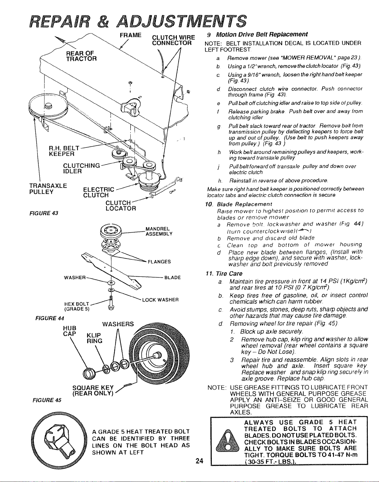
9 Motion Drive Belt Replacement
NOTE: BELT INSTALLATION DECAL IS LOCATED UNDER
LEFT FOOTREST
a Remove mower (see "MOWER REMOVAL" page23).
b Using a 1/2" wrench, remove the clutch Iocator (Fig...43)
c Usingag/16"wrench, Ioosentherighthandbeltkeeper
(Fig. 4,3)
d Disconnect clutch wire connector. Push connector
through frame (Fig. 431,.
e Pull belt off clutching idler' and raise to top side otpultey,
f Release parking brake Push belt over and away from
clutching idler
g Pull belt slack toward rear of tractor Remove belt from
transmission pulley by deflecting keepers to force belt
up and out of pulley. (Use belt to push keepers away
from pulley.) (Fig, 43 )
h Work belt around remainingpulleys and keepers, work-
ing toward transaxle pulley
j Pullbeltforwardoff transaxle pulley and down over
electric clutch
h, Reinstall in reverse of above procedure,
Make sure right hand belt keeper' is positioned correctly between
locator tabs and electric clutch connection is secure
LOCATOR
HEX BOLT _ """ LOCK WASHER
(GRADE 5)
WASHERS
HUB
CAP KLIP
_ RING
SQUARE KEY
(REAR ONLY)
10 Blade Replacement
Rinse mower _o highest positron fo permi_ access to
blades or remove mower
a Remove bolt Iockwasher and washer (F_g 44)
(turn counterclockw_se)(''_)
b Remove and discard old blade
c Clean top and bo[rom of mower housing
d Place new blade between flanges, (Install with
sharp edge down), and secure with washer, lock-
washer and bolt previously removed
11, Tire Care
a Maintain tire pressure in front at 14 PSt (tKg/crrF)
and rear tires at 10 PSI (0 7 Kg/cn'F),
b. Keep tPes free of gasofine, oil, or insect control
chemicals which can harm rubber:
c Avoid stumps, stones, deep ruts, sharp objects and
other hazards that may cause tire damage,
d Removing wheel for tire repair (Fig 45)
1. Block up axle securely_,
2 Remove hub cap, klip ring and washer to allow
wheel removal (rear wheel contains a square
key - Do Not Lose),.
3 Repair tire and reassemble.. Align slots in rear
wheel hub and ax/e. Insert square key
Replace washer and snap kfip ring securely in
axle groove. Replace hub cap.
NOTE: USE GREASE FtTI'INGS TO LUBRICATE FRONT
WHEELS WITH GENERAL PURPOSE GREASE
APPLY AN ANTI-SEIZE OR GOOD GENERAL
PURPOSE GREASE TO LUBRICATE REAR
AXLES,
A GRADE 5 HEAT TREATED BOLT
CAN BE IDENTIFIED BY THREE
LINES ON THE BOLT HEAD AS
SHOWN AT LEFT
24
ALWAYS USE GRADE 5 HEAT
TREATED BOLTS TO ATTACH
BLADES. DONOTUSE PLATED BOLTS°
CHECK BOLTS IN BLADES OCCASION-
ALLY TO MAKE SURE BOLTS ARE
TIGHT,, TORQUE BOLTS TO 41-47 N-m
( 30-35 FT.- LBS,),
it ,l_,l
REPAIR & ADJUSTMENT
WHEN MOUNTING TIRES, UNLESS BEADS
ARE SEATED, OVER iNFLATION CAN
CAUSE AN EXPLOSION
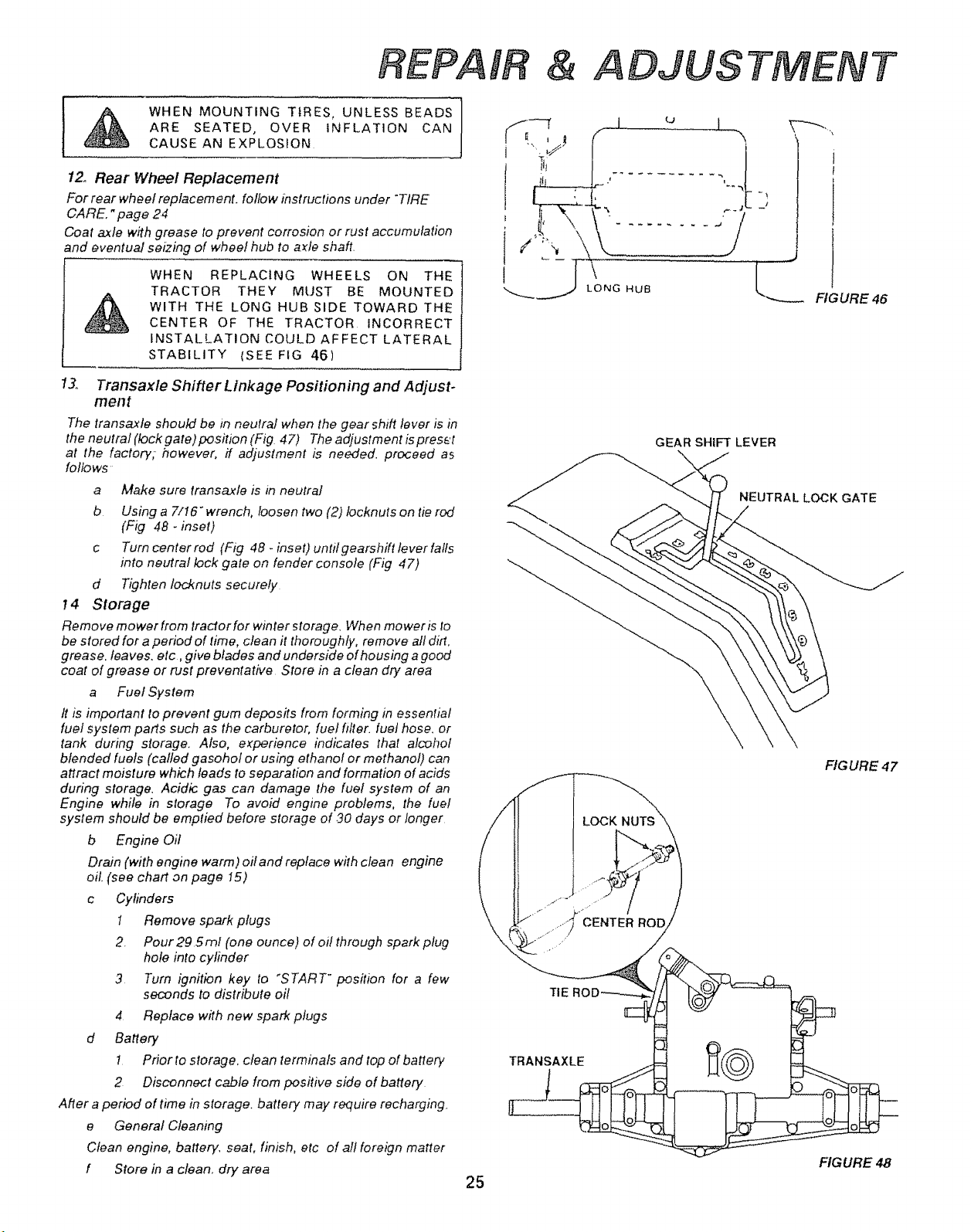
12, Rear Wheel Replacement
For rear wheel replacement, follow instructions under "TIRE
CARE. "page 2.4
Coat axle with grease to prevent corrosion or rust accumulation
and eventual seizing of wheel hub to azle shaft.
WHEN REPLACING WHEELS ON THE
TRACTOR THEY MUST BE MOUNTED
WITH THE LONG HUB SIDE TOWARD THE
CENTER OF THE TRACTOR INCORRECT
INSTALLATION COULD AFFECT LATERAL
STABILITY (SEE FIG 46)
13., Transaxle Shifter Linkage Positioning and Adjust-
merit
The transaxte should be in neutral when the gear shift lever is in
the neutral (!ock gate) position (Fig 47) The adjustment is press't
at the factory; however, ff adjustment is needed, proceed as
follows
a
b
Make sure transaxle is in neutral
Using a 7/16" wrench, loosen two (2) locknuts on tie rod
(Fig 48 - inset)
c Turn center rod (Fig 48- inset) untilgearshfft lever falls
into neutral lock gate on fender console (Fig 47)
d Tighten locknuts securely
14 Storage
Remove mower from tractor for winter storage. When mower is to
be stored for a period of time, clean it thoroughly, remove all dirt.
grease, leaves, etc ,give blades and underside of housing a good
coat of grease or rust preventative Store in a clean dry area
a Fuel System
It is important to prevent gum deposits from forming in essential
fuel system parts such as the carburetor, fuel filter, fuel hose. or
tank during storage. Also, e_perience indicates that alcohol
blended fuels (called gasohol or using ethanol or methanol) can
attract moisture which leads to separation and formation of acids
during storage. Acidic gas can damage the fuel system of an
Engine while in storage To avoid engine problems, the fuel
system should be emptied before storage of 30 days or longer
b Engine Oil
DraJn (with engine warm) oit and replace with clean engine
oil. (see chart on page I5)
c Cylinders
1 Remove spark plugs
2. Pour 295rnl (one ounce) of oil through spark plug
hole into cy#nder
3 Turn ignition key to "START" pos#ion for a few
seconds to distribute oil
4 Replace with new spark plugs
d Battery
! Prior to storage, clean terminals and top of battery
2 Disconnect cable from positive side of battery
After a period of time in storage, battery may require recharging.
e General Cleaning
Clean engine, battery, seat, finish, etc of all foreign matter
f Store in a clean, dry area
25
\
GEAR SHIFT LEVER
FIGURE 46
LOCK
TIE
TRANSAXLE
NEUTRAL LOCK GATE
FIGURE 47
FIG URE 48
TROUBLESHOOTING
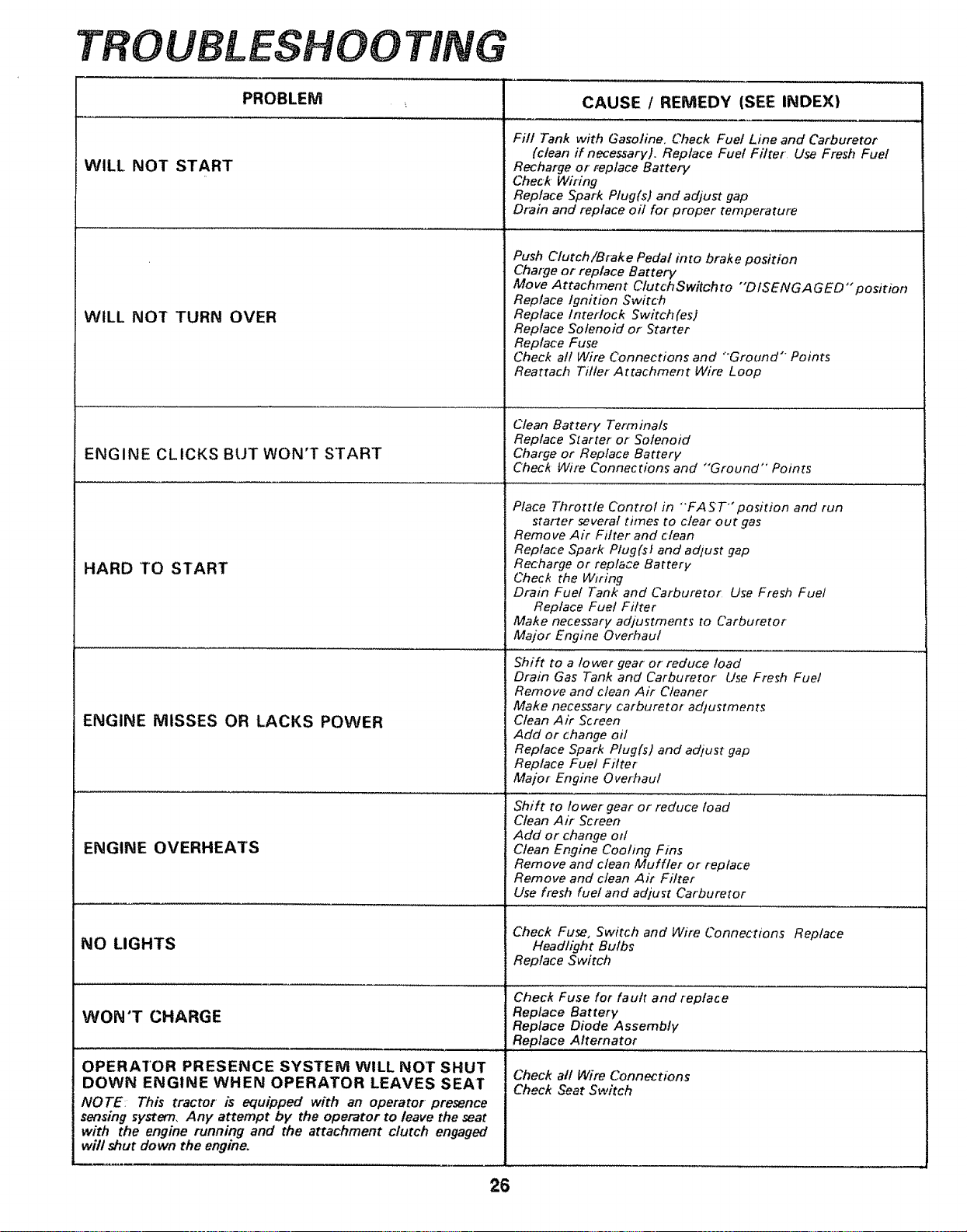
WILL NOT START
WILL NOT TURN OVER
ENGINE CLICKS BUT WON'T START
HARD TO START
ENGINE MISSES OR LACKS POWER
PROBLEM _ CAUSE / REMEDY (SEE INDEX)
ENGINE OVERHEATS
NO LIGHTS
WON'T CHARGE
OPERATOR PRESENCE SYSTENI WILL NOT SHUT
DOWN ENGINE WHEN OPERATOR LEAVES SEAT
NOTE: This tractor' is equipped with an operator presence
sensing system, Any attempt by the operator to leave the seat
with the engine running and the attachment clutch engaged
will shut down the engine.
Fil! Tank with Gasoline, Check Fuel Line and Carburetor
(clean if necessary). Replace Fuel Filter Use Fresh Fuel
Recharge or replace Battery
Check' Wiring
Replace Spark Plug(s) and adjust gap
Drain and replace oit for proper temperature
Push Clutch/Brake Pedal into brake position
Charge or replace Battery
Move Attachment ClutchSwitch to "'D ISENGA G ED '" position
Replace Ignition Switch
Replace Interlock Switch (es)
Replace Solenoid or Starter
Replace Fuse
Check all Wire Connections and "Ground" Points
Reattach Tiller Attachment Wire Loop
Clean Battery TerminaLs
Replace Starter or Solenoid
Charge or Replace Battery
Check Wire Connections and "Ground" Points
Place Throttle Control in -FA ST'" position and run
staFter several times to clear out gas
Remove Air Filter and clean
Replace Spark' Plug(sf and adjust gap
Recharge or replace Battery
Check the Wiring
Drain Fuel Tank and Carburetor Use Fresh Fuel
Replace Fuel Filter
Make necessary adjustments to Carburetor
Major Engine Overhaul
Shift to a lower gear or reduce toad
Drain Gas Tank and Carburetor Use Fresh Fuel
Remove and clean Air Cleaner
Make necessary carburetor adtustments
Clean Air Screen
Add or change oil
Replace Spark Plug(s) and adjust gap
Replace Fuel Filter
Major Engine Overhaul
Shift to lower gear or reduce load
Clean Air Screen
Add or change od
Clean Engine Cooling Fins
Remove and clean Muffler or replace
Remove and clean Air Filter
Use fresh fuet and adjust Carburetor
Check Fuse, Switch and Wire Connections Replace
Headlight Bulbs
Replace Switch
Check Fuse for fault and replace
Replace Battery
Replace Diode Assembly
Replace Alternator
Check all Wire Connections
Check Seat Switch
26
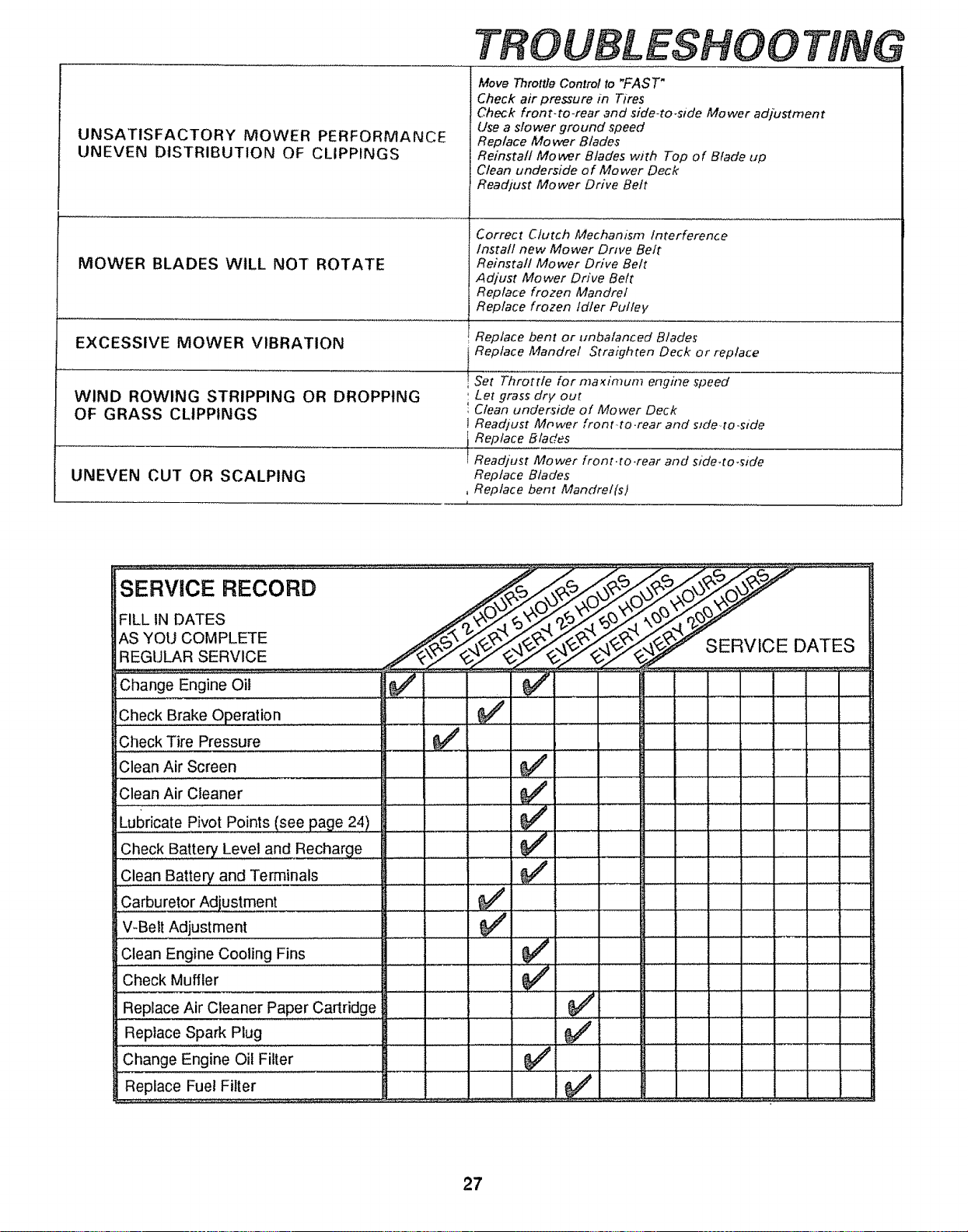
TROUBLESHOOTING
UNSATISFACTORY MOWER PERFORMANCE
UNEVEN DISTRIBUTION OF CLIPPINGS
MOWER BLADES WILL NOT ROTATE
EXCESSIVE MOWER VIBRATION
WIND ROWING STRIPPING OR DROPPING
OF GRASS CLIPPINGS
UNEVEN CUT OR SCALPING
Move Throttle Control to "FAST"
Check air pressure in Tires
Check front-to-rear and side-to.side Mower adjustment
Use a slower ground ,speed
Replace Mower Blades
Reinstall Mower Blades with Top of Blade up
Clean underside of Mower Deck
Readjust Mower Drive Bett
Correct Clutch Mechanism Interference
/nstal/ new Mower Drive Belt
Reinstall Mower Drive Belt
Adjust Mower Drive Belt
Replace frozen Mandrel
Replace frozen td/er Pulley
Replace bent Or unbalanced Blades
Replace Mandrel Straighten Deck or replace
Set Throttle for maximum engine speed
Let grass dry out
Clean underside of Mower Deck
Readiust Mower front.,to.rear and slde,,to,side
Replace Blades
Readjust Mower front.to.rear and side.to.side
Replace Blades
, Replace bent Mandrel(s)
i
ERVICE RECORD
FILL IN DATES
AS YOU COMPLETE
REGULAR SERVICE
Check Brake Operation ................ _'
Check Tire Pressure ...........................
Clean Air Screen
Clean Air Cleaner
Lubricate Pivot Points (see page 24 )
Check Battery Level and Recharge
Clean Battery and Terminals
Carburetor Adjustment
V-Bell Adjustment
Clean Engine Cooling Fins .......................
Check Muffler
J
J
J
Replace Air Cleane r paper,,,,c,artrid,ge.......
Replace Spark Plug
Change Engine Oil Filter
Replace Fuel Filter
J
SERVICE DATES
I
27
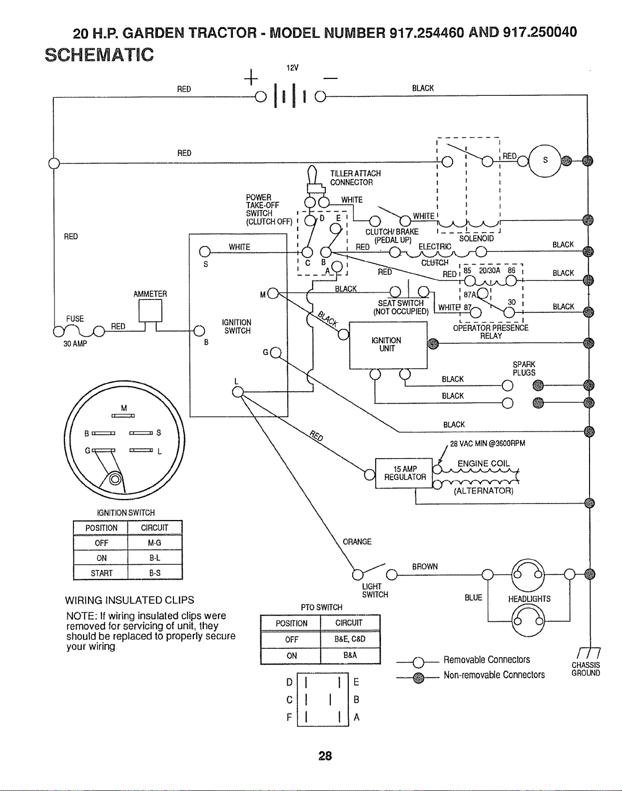
20 H.P. GARDEN TRACTOR - MODEL NUMBER 917.254460 AND 917.250040
12V
SCHEMATaC
RED
RED
FUSE
30 AMP
AMMETER
[--q
RED .... LT_ ................
s
POWER
TAKE-OFF
SWITCH i
(CLUTCHOFF)
I
r C
t
IGNITION
SWITCH
B
Gq
iGNiTiONSWITCH
POSITION CIRCUIT
OFF M-G
ON B-L
START B_S
WIRING INSULATED CLIPS
NOTE: if wiring insulated clips were
removed for servicing of unit, they
should be replaced to properly secure
your wiring,
SEAT SWITCH
(NOT OCCUPIED) --
IGNITION
UNIT
I 87A
i. i
OPERATORPRESENCE
RElAY
BLACK
8lACK
BLACK
BlACK
SPARK
PLUGS
© ®
© @
BlACK
15 AMP
REGULATOR
t
28 VAC MIN@3600RPM
ORANGE
o
LIGHT
SWITCH
PTOSWITCH
POSITION CIRCUIT
OFF B&E, C&D
ON £&A
D I I E
c ! I B
F I 1 A
BROWN
©
@
RemovableConnectors
Non-removableConnectors
CHASSIS
GROUND
28
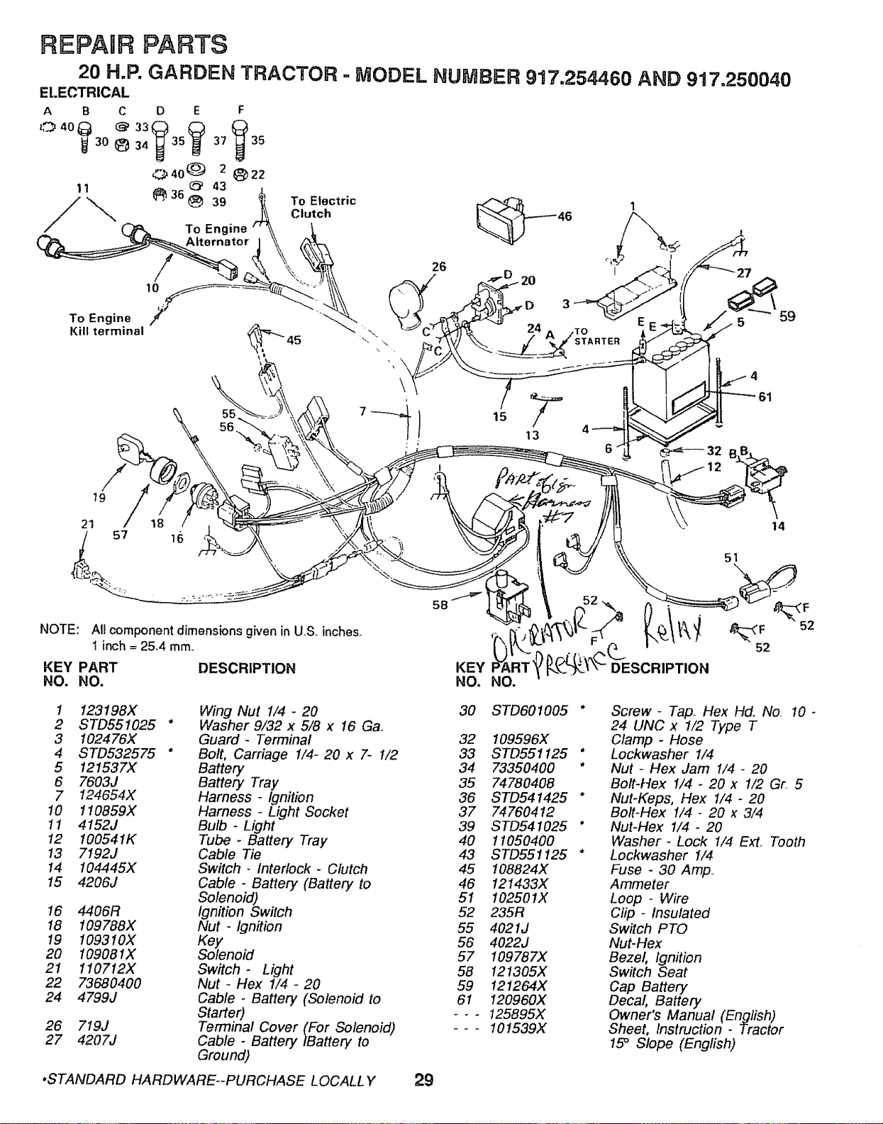
REPAmF{PARTS
20 H.P, GARDEN TRACTOR - MODEL NUMBER 917.254460 AND 917,250040
ELECTRICAL
A B C D E F
30 {_ 34 35 37 35
_._40(_ 2 _22
11 _. 36 (_ 43
39
/\
To Engine
To Electric
Clutch 46
10
To Engine
Kill terminal
26
13
6
59
79
21
NOTE: All component dimensions given in U,S. inches_
1 inch = 25,4 mm,
KEY PART DESCRIPTION
NO. NO.
t 123198X
2 STD551025 *
3 102476X
4 STD532575 *
5 121537X
6 7603J
7 124654X
10 110859X
11 4152j
t2 10054IK
13 7192J
14 I04445X
15 4206J
16 4406R
18 109788X
19 !093 !OX
20 !09081X
21 110712X
22 73680400
24 4799J
26 719J
27 4207J
Wing Nut 1/4 - 20
Washer 9/32 x 5/8 x 16 Ga.,
Guard- Terminal
Bolt, Carriage I/4- 20 x 7- 1/2
Battery
Battery Tray
Harness - Ignition
Harness - Light Socket
Bulb - Light
Tube - Battery Tray
Cable Tie
Switch - Interlock- Clutch
Cable - Battery (Battery to
Solenoid)
Ignition Switch
Nut - Ignition
Key
Solenoid
Switch- Light
Nut _ Hex 1/4 - 20
Cable. Battery (Solenoid to
Starter)
Terminal Cover (For Solenoid)
Cable - Battery tBattery to
Ground)
14
51
30 STD601005
52
32 109596X
33 STD551125 *
34 73350400 *
35 74780408
36 STD541425 *
37 74760412
39 STD541025 *
40 11050400
43 STD551125 *
45 108824X
46 121433X
51 102501X
52 235R
55 4021J
56 4022J
57 109787X
58 121305X
59 121264X
61 120960X
_.- 125895X
--- 101539X
Screw _ Tap,, Hex Hd. No. 10 -
24 UNC x 1/2 Type T
Clamp - Hose
Lockwasher I/4
Nut - Hex Jam I/4 - 20
Bolt-Hex 1/4 - 20 x I/2 Gr,, 5
Nut-Keps, Hex 1/4- 20
Bolt-Hex i/4 - 20 x 3/4
Nut-Hex 1/4 - 20
Washer- Lock 1/4 ExL Tooth
Lockwasher I/4
Fuse - 30 Amp.,
Ammeter
Loop * Wire
Clip - Insulated
Switch PTO
Nut-Hex
Bezel ignition
Switch Seat
Cap Battery
Decal Battery
Owner's Manual (English)
Sheet, Instruction- Tractor
15° Slope (English)
.STANDARD HARDWARE--PURCHASE LOCALL Y 29
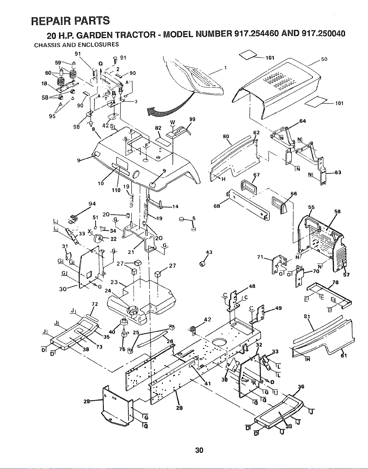
REPAIR PARTS
20 H,R GARDEN TRACTOR = MODEL NUMBER 917.254460 AND 917=250040
CHASSIS AND ENCLOSURES
91 @_--101
59"_ Q _.91 \, \
60:
10
110
72
J
82
W
99
27
43
68
8O
101
'" 63
7 7
42
73
32
3O
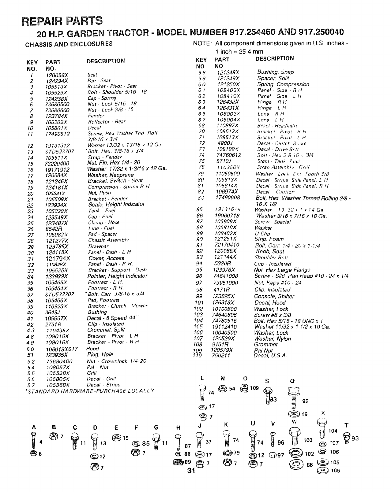
REPAUR PARTS
20 H.P. GARDEN TRACTOR = MODEL NUMBER 917.254460 AND 917.250040
CHASSIS AND ENCLOSURES
KEY
NO
1
2
3
4
5
5
7
8
9
!0
tl
12
!.3
14
t5
15
t7
18
19
2O
2!
22
2.3
24
25
26
27
28
29
30
,21
32
33
34
35
36
37
38
39
40
41
42
43
48
49
5o
51
52
54
55
56
57
NOTE:
All component dimensions given in US inches-
! inch = 25 4 mm
"STANDARD HARDWARE.-PURCHASE L OCALL Y
PART DESCRIPTION KEY PART DESCRIPTION
NO. NO NO
120066X Seat 5 8 121248X Bushing, Snap
t24294X Pan ...Seat 5 9 t2t249X Spacer. Spld
t055t3X Bracket- Pivot • Seat 60 t21250X Spring, Compression
t05529X Bott . Shoulder 5/t6. 18 6 ; 108403X Panel . Side R H
124238X Cap. Spring 6 2 ] 08410X Panel S_de L H
73680500 Nut. Lock 5/15. 18 6 3 126432X Hinge R H
73680600 Nut. Lock .3/8. I6 5 4 126431X Hinge L H
123784)< Fender 6 6 I 06003X Lens R H
I06.202X Reflector Rear 6 7 I06004X Lens L H
10580t _( Decal 58 1lOB97X Bezel . Headh!ih_
t74.90612 .Screw, Hex Washer Thd Roll 70 10851.2X Bracket Pivot R H
3/8-16 _ 3/4 71 !08513X Bracket Pt_.'(')t Z t_
19t31.3t2 Washer t3/32 _ t3/!5 _ 12 Ga 72 4900J Decal . Clutch Bl,lke,
S TD523707 "Bolt. Hex. 3/8. 16 x 3/4 73 109t99X Decal Dmv_ _,-/_
t055ttx Strap - Fender 24 74760612 Bolt Hex ._ 8 15 , 3/,_
73220400 Nut, Fin_ Hex 1/4-20 75 8710J Stem - Tank F,lei
19171912 Washer 17/32 x 1-3/16 x 12 G& 76 110350>( Straf) Assemhlv _r,il
120684X Washer, Neoprene 79 t 1050500 Washer Lo_ k E_r T_oth .?/8
121246)( Bracket, Switch. 5eat 80 1068t3X Decal Strq_e %1_,Panel. L H
124181X Compression - .Spring R H 81 tD6814X Decal 5rrq_e Side Panel R H
10553tX Nut, Push 8.2 106974X Deca! Cbutloz_
105509X Bracket. Fender 83 I7490608 Bolt, Hex Washer Thread Rolling 3/8 -
123934X Scale, Height Indicator 16 X 1/2
106020X Tank . Fuel 85 19131614 Washer 13 32, 1 _ 14 Ga
123549X Cap. Fuel 86 19060718 Washer3!16 x 7/16 x 18 Ga.
123487X Clamp- Hose 87 t06909X Screw. Special
8542R Line. Fuel 88 106910X Washer
I06082X Pad. Spacer 89 108402X U.C/ip
1212772< Chassi_ Assembfp* 90 t21251X Strip. Foam
123785X Drawbar 91 72170410 Bolt, Cart, I/4.20 x 1ol/4
124118X Panel. Dash. L H 92 120068X Knob, Seat
121794X Cover, Access 9.3 I21 t44X Shoulder Bolt
110828X Panel ..Dash - R H 94 5320R C'hp .. Insulated
105525X Bracket- Support- Dash 95 123976>( Nut, Hex Large Flange
123933X Pointer, Height Indicator 96 74641008 Screw - Sltd Pan Head #10 - 24 x 1/4
105465>( Footrest. L H. 97 73951000 Nut, Keps //10- 24
105454X Footrest. R H 98 4!7IR Crib. Insulated
STD533707 "Bolt. Carr 3/8..16 x 3/4
99 t23825X Console, Shifter
105466X Pad, Footrest
110923X Bracket. Cturch Mower 101 126313X Decal, Hood
3645J Bushing 102 10100800 Washer, Lock
!05567X Decal - 6 Speed 44 " I03 74640806 Screw #8 x 3/8
2751R Clip - Insulated 104 74780516 Bolt, Hex 5/16 - 18 UNC x 1
105 19112410 Washer 11/32x 1 1/2x lOGa
! 10436X Grommet, Split 106 10040500 Washer, Lock
709015X Bracket . Pivot . L H
7090 t 6X Bracket . Pivot . R H 107 120529X Washer, Nylon
108 9 I51R Grommet
I06013X017 Hood t09 120579>( Pal Nut
123935X Plug, Hole 110 750211 Decal, U_S A
73680400 Nut Crowntock 1/4,20
108067X Pal. Nut
105528X Grill
105806X Decal _ Gnff L N 0 S Q
105568x Decal Stripe
G
_7
H J K
74
1 N 87
8 ,89 ®7
31
A B C D E F
11 13 @_85
_92
(_16 X
U V w _ T
74 96 t03 @ 107 93
@12 _)97 _102 @ _06
7 @ 86 _'°5
105
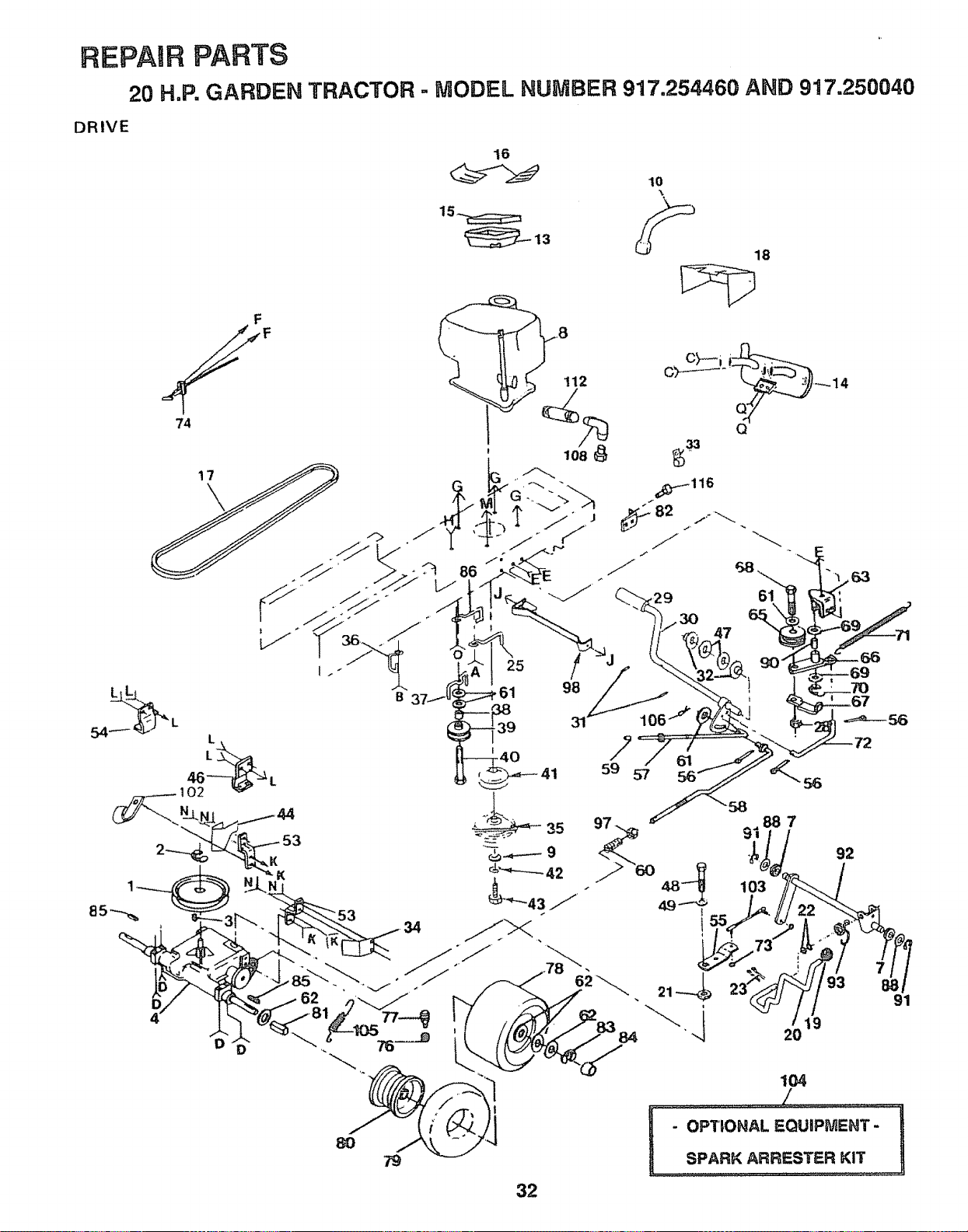
REPAIR PARTS
20 H,P. GARDEN TRACTOR - NODEL NUNBER 917.254460 AND 917.250040
DRIVE
16
7
59 57
92
91
8O
32
104
' PTIONAL EQUIPMENT-
L
SPARK ARRESTER _
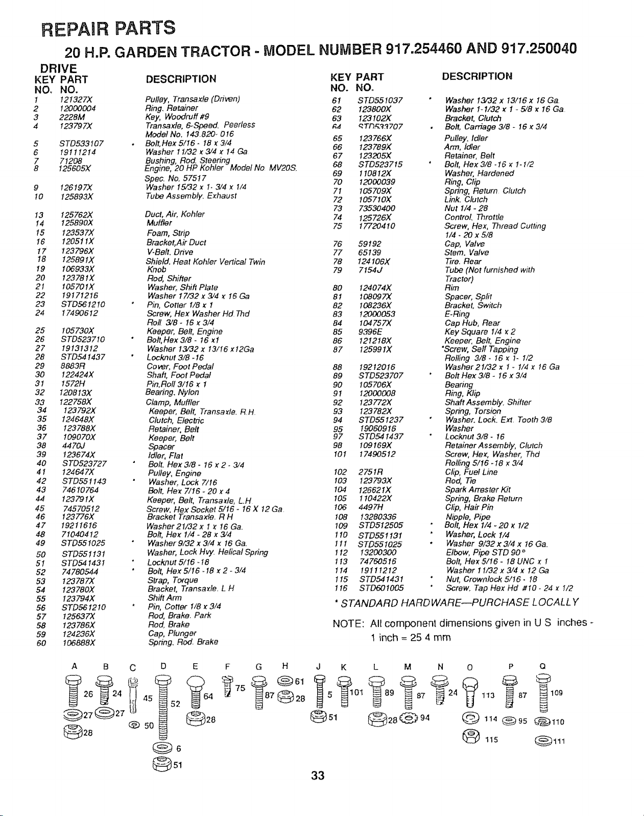
REPAIR PARTS
20 H.P. GARDEN TRACTOR - MODEL NUMBER 917.254460 AND 917.250040
DRIVE
KEY PART
NOo NO.
I t21327X
2 12000004
3 2228M
4 123797X
5 STD533107
6 I9t 1 t214
7 71208
8 I25605X
9 I26t97X
t 0 125893X
13 125762X
! 4 t 25890X
t5 t23537X
I6 12051 IX
17 t23796X
t8 12589 tX
19 106933X
20 12378 tX
21 I0570IX
22 19171216
23 STD56t2!0
24 17490612
25 t05730X
26 STD5237t0
27 19131312
28 STD54 t437
29 8883R
30 t22424X
3 t 1572H
32 I20813X
33 I22758X
34 t 23 79 2X
35 t24648X
36 !23788X
37 109070X
38 4470J
39 !23674X
40 STD523727
4t 124647X
42 STD551143
43 74610764
44 t2379tX
45 74570512
46 t23776X
47 19211616
48 71040412
49 STD55t025
50 STD55tt3t
5! STD54143t
52 74780544
53 t23787X
54 123780X
55 I23794X
56 STD561210
57 t25637X
58 !23786X
59 I24236X
60 ! 06888X
DESCRIPTION
Pulley, Transaxte (Driven)
Ring. Retainer
Key, Woodruff #9
Transaxfe, 6-Speed. Peerless
Model No. 143820-0t6
Bolt, Hex 5/t6 - t8 _ 3/4
Washer t t732 _ 3/4 x 14 Ga
BEnUshing,Rod. Steering
gine, 20 HP Kohler Model No MV20S,
Spec. No. 57517
Washer t5/32 x t_ 374 x t/4
Tube Assembly. Exhaust
Duct, Air, Kohfer
Muffler
Foam, Strip
Bracket, Air Duct
V-Belt. Ddve
Shield. Heat Kohler Vertical Twin
Knob
Rod, Shifter
Washer, Shift Plate
Washer I7/32 x 3/4 _: I6 Ga
* Pin, Cotter 1/8 _ I
Screw, Flex Washer Hd Thd
Roll 3/8.16 _ 3/4
Keeper, Belt, Engine
Belt, Hex 3/8- 16 _t
Washer t37"32 x t3/t6 xt2Ga
Lock.nut 3/8 - 16
Cover, Foot Pedal
Shaft, Foot Pedal
Pin.Roll 3/16 _: 1
Bearing. Nylon
Clamp, Muffler
Keeper, Belt, Transa):le. RH
Clutch, Electric
Retainer, Belt
Keeper° Belt
Spacer
Idler, Flat
" Bolt. Flex 3/8 - 16 _:2.3/4
Pulley, Engine
Washer. Lock 7/t6
Bolt. Hex 7116 - 20 x 4
Keeper, Belt, Transa_fe, L.H
Screw, Hex Socket 5/I6 - I6 X 12 Ga
Bracket Transaxfe. R H
Washer 21/32 x t _ t6 Ga
Bolt, Flex 1/4 - 28 x 3/4
* Washer 9/32 x 3/4 _: 16 Ga.
Washer, Lock Hv_ Helical Spring
* Locknut 5/I6 -!8
* Bolt, Hex 5/t6_ t8 y,2- 3/4
Strap, Torque
Bracket, Transa)fle. L H
Shift Arm
* Pin, Cotter t/8 _ 3/4
Rod, Brake. Park
Rod. Brake
Cap, Plunger
Spring. Rod. Brake
KEY PART DESCRIPTION
NO. NO.
61 STD55t037 * Washer 13/32 x t3/I6 x t6 Ga
62 123800X Washer 1-1132 _ 1 - 5/8 _ !6 Ga
63 123102X Bracket, Clutch
qTf3.£_'3707 • Bolt, Carriage 3/8 - I6 _ 3/4
65 t23766X Pulley, Idler
66 123789X Arm, Idler
67 123205X Retainer, Belt
68 STD5237t5 " Bolt, Flex 3/8. I6 _ t- 1/2
69 t t0812X Washer, Hardened
70 12000039 Ring, Clip
71 105709X Spdng, Return Clutch
72 t057t0X Link. Clutch
73 73530400 Nut 1/4 - 28
74 125726X Control Throttle
75 17720410 Screw, Hex, Thread Cutting
I/4 - 20 x 5/8
76 59192 Cap, Valve
77 65139 Stem, Valve
78 124106)( ?7re. Rear
79 715-4J Tube (Not furnished with
Tractor)
80 124074X Rim
81 108097X Spacer, Split
82 108236)( Bracket, Switch
83 12000053 E.Ring
84 t04757X Cap Hub, Rear
85 9396E Key Square I/4 _ 2
86 I2t2t8X Keeper, Be#, Engine
87 125991X "Screw, Serf Tapping
Rolling 3/B- I6 _: t- I/2
88 19212016 Washer21/32 x I _ 1/4 _: t6 Ga
89 STD523707 Belt Hex 3/8- I6 x 3/4
90 t 05 706X Bearing
91 I2000008 Ring, Klip
92 t23772X Shaft Assembly. Shifter
93 t23782X Spring, Torsion
94 STD551237 Washer. Lock. Ext Tooth 3/8
95 19060916 Washer
97 STD54 t437 Locknut 3/8. t6
98 t09169X Retainer Assembly, Clutch
10t 17490512 Screw, Hex, Washer, Thd
Rolling 5/t6-18 x 3/4
t02 2751R Clip, Fuel Line
103 !23793X Rod, 77e
104 126621X Spark Arrester Kit
t05 1 !0422X Spring, Brake Return
106 4497H Clip, Hair Pin
t08 13280336 Nipple, Pipe
t09 STD512505 Bolt, Flex 1/4 - 20 x t/2
ti0 STD551131 ' Washer, Lock I/4
! t I STD551025 * Washer 9/32 x 3/4 x 16 Ga
t 12 13200300 Elbow, Pipe STD 90 °
1t3 74760516 Bolt, Hex S/16- 18 UNC _ !
It4 19111212 Washer 11/32 x 3/4 x 12 Ga
1 I5 STD54143t Nut, Crowntock 5116. I8
1t6 STD60tO05 Screw. Tap Hex Hd #10- 24 _ 1/2
* STANDARD HARDWARE--PURCHASE LOCALL Y
NOTE: All component dimensions given in U S inches -
1 inch = 25 4 mm
A B C D
t 45 2
@ 5o
@sl
E F G H
@28
J K L M
33
N O P Q
tt5
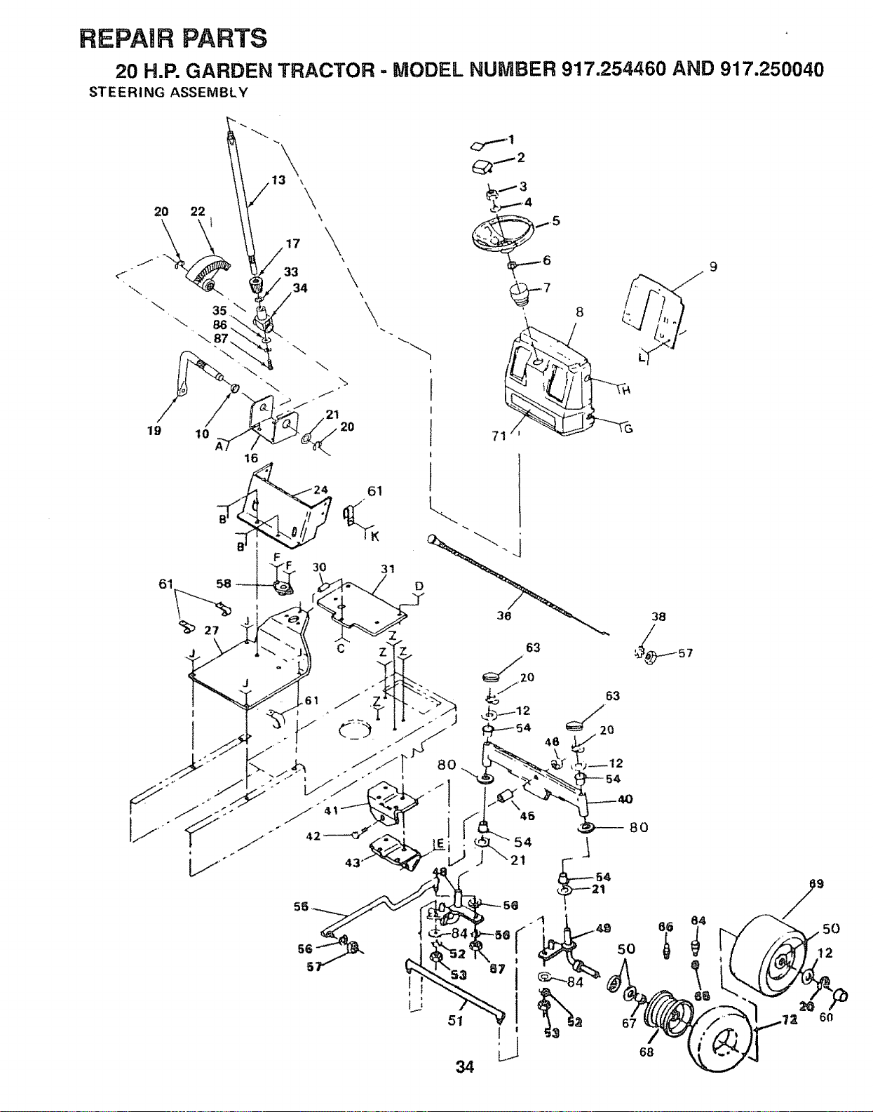
REPAIR PARTS
20 H.P. GARDEN TRACTOR - MODEL NUMBER 917.254460 AND 917.250040
STEERING ASSEMBLY
19
61
31
D
9
6n
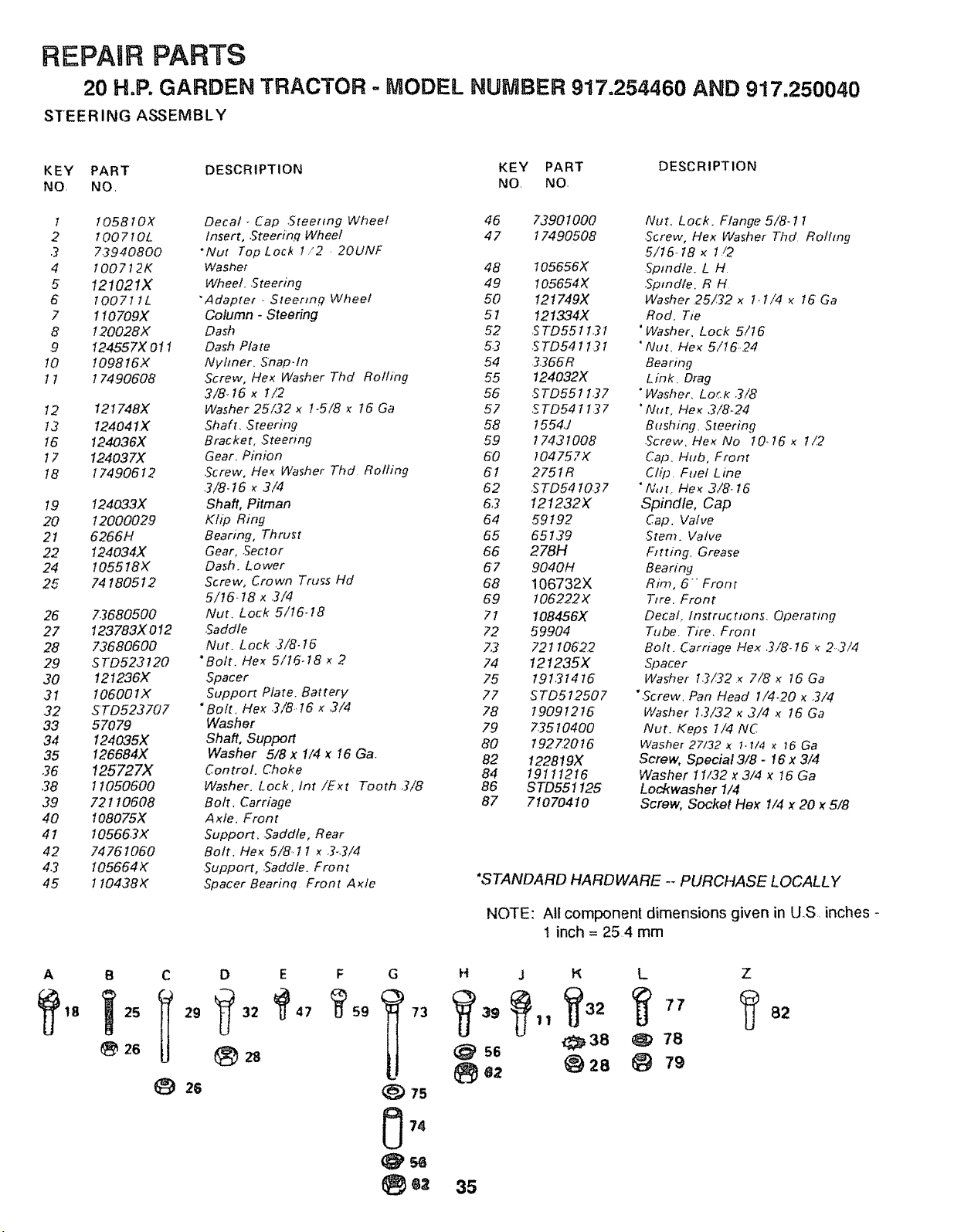
REPAIR PARTS
20 H.P. GARDEN TRACTOR - MODEL NUMBER 917,254460 AND 917.250040
STEERING ASSEMBLY
KEY PART DESCRIPTION KEY PART DESCRIPTION
NQ NO, NO, NO,
1 1058t0X Decal _ Cap Steering Wheel 46 73901000 Nut, Lock. Flange 5/8-1 t
2 100710L Insert, Steering Wheel 47 17490508 .Screw, Hex Washer Thd Rolling
.2 73940800 "Nut Top L ock I "2 - 20UNF 5/15.. 18 x I/2
4 100712K Washer 48 105656X .Spindle. L H
5 121021X Wheel. ,Steering 49 105654X Spindle. R H
6 100711L "Adapter . Steermq Wheel 50 121749X Washer,25/32 x t-t/4 _ 15' Ga
7 1 t0709X Column - Steering 5t 121334X Rod. Tie
8 120028X Dash 52 STD55113I "Washer, Lock 5/t6
9 I24557X 011 Dash Plate 53 _STD541 t31 "Nut, Hex 5/16.24
I0 I098t6X Nyhner. Snap-fn 54 3366R Bearing
t 1 17490608 5crew, Hex Washer Thd Rolling 55 124032X Link_ Drag
3/8_ 15 x !/2 56 STD5511.37 "Washer, Lo._,l_ 3/8
t2 121748X Washer 25/32 x t-5/8 _ !6 Ga 57 STD541 t37 'Nut, Hex 3/8_24
t3 124041X Shaft, Steering 58 t554J Bushing, Steering
t5 124036X Bracket, ,Steering 59 t743 t008 ,Screw, He_ No 10, 15 x t/2
t 7 124037)( Gear, Pinion 50 104757X Cap. Hub, Front
t8 17490512 .Screw, He_ Washer Thd Rolling 61 275tR Clip. Fuel Line
3/8-t5 x 3/4 62 STD54 t037 ° iV, n. He_ 3/8-I6
19 124033X Shaft, Pitman 53 121232X Spindle, Cap
20 12000029 Kfip Ring 54 59t9.2 Cap. Valve
21 6266H Bearing, Thrust 65 65139 Stem. Valve
22 t24034X Gear, .Sector 66 278H Fitting, Grease
24 I05518X Dash. Lower 67 9040H Beanng
25 74180512 Screw, Crown Truss Hd 68 106732X Rim, 6" Front
5/!6.18 x ,3/4 69 t06222X Tire. Front
26 73680500 Nut. Lock 5/t6-t8 71 108456X Decal, lnstructtons, Operating
27 123783X012 .Saddle 72 59.904 Tube. Tire, Front
28 73680600 Nut. Lock .3/8-t5 7,3 72I 10622 Bolt. Carriage Flex 3/8_ t5 '_ 2..3/4
29 STD523120 "Bolt. t-tex 5/t6_18 x 2 74 !21235X Spacer
30 121236X Spacer 75 19131416 Washer t.3/22 _ 7/8 _ t6 Ga
3! t06001X Support Plate. Battery 77 STD512507 "Screw, Pan Head I/4-20 x 3/4
32 STD523707 "Bolt. Hex 3/8.t6 x 3/4 78 19091215 Washer 1,3/32 _ 3/4 x 16 Ga
33 57079 Washer 7.9 7.3510400 Nut. Keps 1/4 NC
34 124035X Shaft, Support 80 192Z2016 Washer 27/32 x 1.1/4 _ _6 Ga
35 !26684X Washer 5/8 x 1/4 _ 16 Ga 82 122819X Screw, Special3/8 - 16 x 3/4
.36 125727X Control. Choke 84 191 t t216 Washer 11/32 _ 3/4 x t6 Ga
38 11050500 Washer. Lock, tnt /Ext Tooth 3/8 86 STD551125 Lockwasher 1/4
39 72110608 Bolt, Carriage 87 71070410 Screw, Socket Flex !/4 x 20 x 5/8
40 I08075X Axfe. Front
41 105663X Support. Saddle, Rear
42 7476 t050 Bolt. He_ 5/8. t I _ 3,3/4
4.3 t05664X .Support, .Saddle. Front
45 ! 10438)< Spacer Bearinq Front Axle *STANDARD HARDWARE -- PURCHASE LOCALLY
NOTE: All component dimensions given in US, inches -
t inch = 25 4 mm
A B C D E F G H j P_ L Z
_62 @28 @ 79
35
82
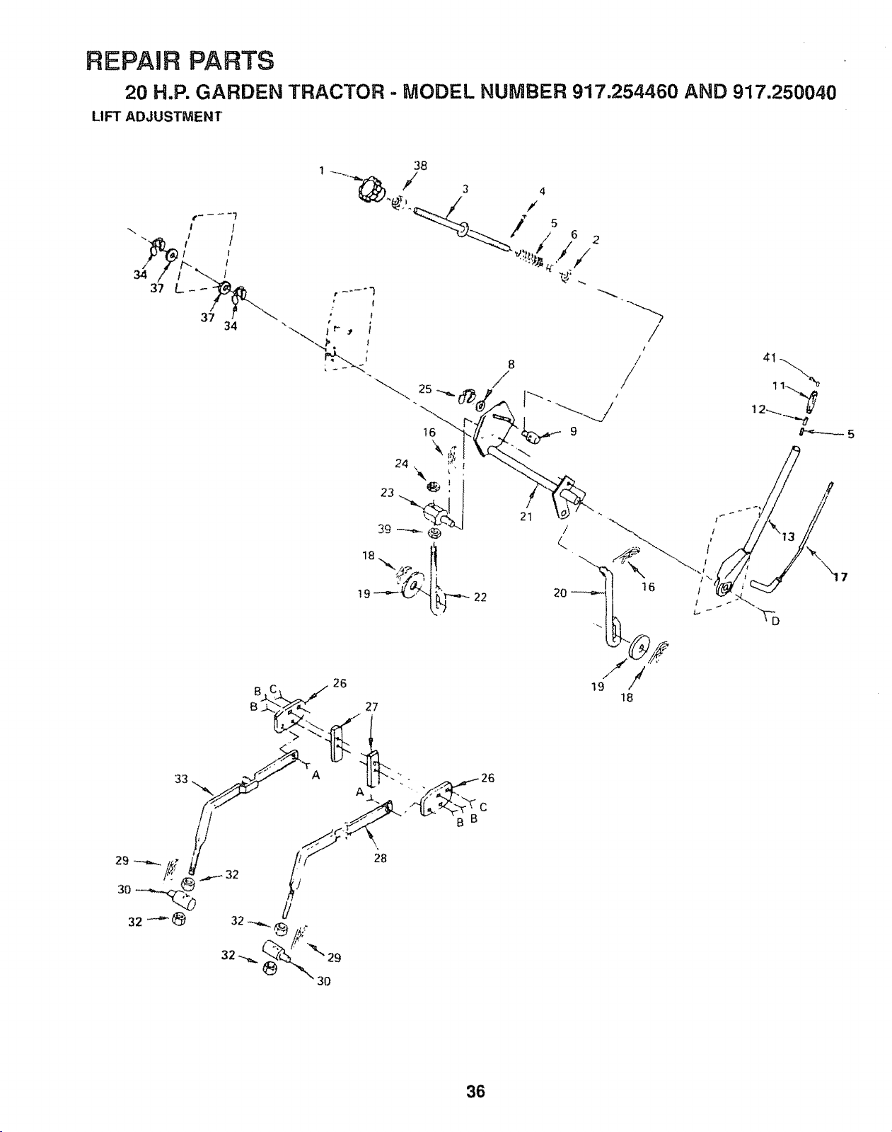
c
s_
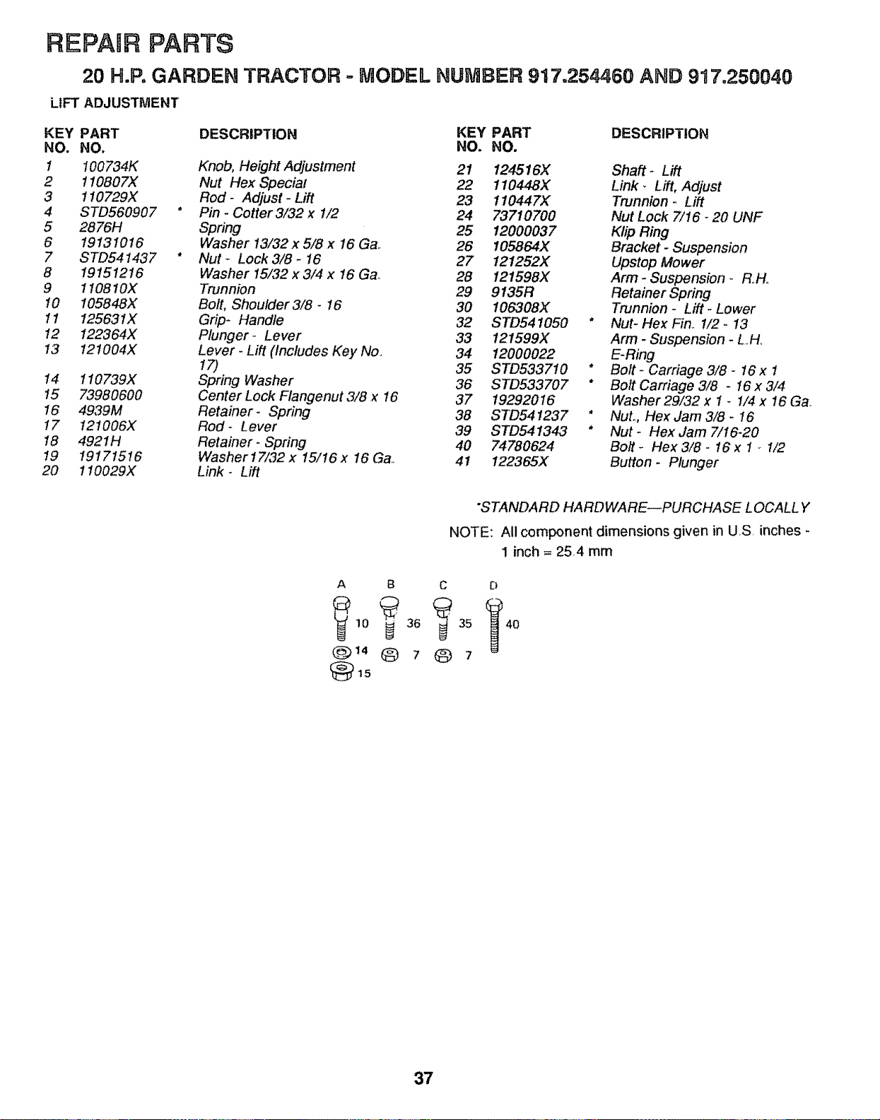
REPAIR PARTS
20 H.Po GARDEN TRACTOR ° MODEL NUMBER 917.254460 AND 917o250040
LIFT ADJUSTMENT
KEY PART DESCRIPTION KEY PART DESCRIPTION
NO. NO. NO. NO.
1 100734K Knob, HeightAdjustment 21 124516X Shaft _ Lift
2 1!0807X Nut Hex Special 22 110448X Link- Lift, Adjust
3 110729X Rod - Adjust - Lift 23 110447X Trunnion - Lift
4 STD560907 * Pin - Cotter3/32 x 1/2 24 73710700 Nut Lock 7/16 _20 UNF
5 2876H Spring 25 12000037 Klip Ring
6 19131016 Washer 13/.32x 5/8x 16 Ga. 26 I05864X Bracket- Suspension
7 STD541437 * Nut - Lock 3/8 - 16 27 121252X Upstop Mower
8 19151216 Washer 15/32 x 3/4 x 16 Ga,. 28 121598X Arm- Suspension _ RoH_
9 110810X Trunnion 29 9135R Retainer Spring
10 I05848X Bolt, Shoulder3/8- 16 30 106308X Trunnion- Lift-Lower
11 125631X Grip* Handle 32 STD541050 * Nut- Hex Fin. 1/2- 13
12 122364X Plunger - Lever 33 !21599X Arm - Suspension - L..H_
13 121004X Lever - Lift (includes Key No. 34 12000022 E-Ring
17) 35 STD533710 * Bolt- Carriage 3/8 - 16 x 1
14 110739X Spring Washer 36 STD533707 * Bolt Carriage 3/8 - 16 x 3/4
15 73980600 Center Lock Flangenut 3/8 x !6 37 19292016 Washer 29/32 x 1 - 1/4 x 16 G&
16 4939M Retainer- Spring 38 STD541237 " Nut°, Hex Jam 3/8 - 16
17 121006X Rod- Lever 39 STD541343 * Nut- Hex Jam 7/16-20
18 4921H Retainer- Spring 40 74780624 Bolt- Hex 3/8 - 16 x 1 - 1/2
I9 19171516 Washer17/32 x 15/16x 16 Ga., 41 122365X Button - Plunger
20 110029X Link- Lift
"STANDARD HARDWARE--PURCHASE L OCALL Y
NOTE: All component dimensions given in U.S. inches -
1 inch = 25,4 mm
A B C D
@14@7@7
37
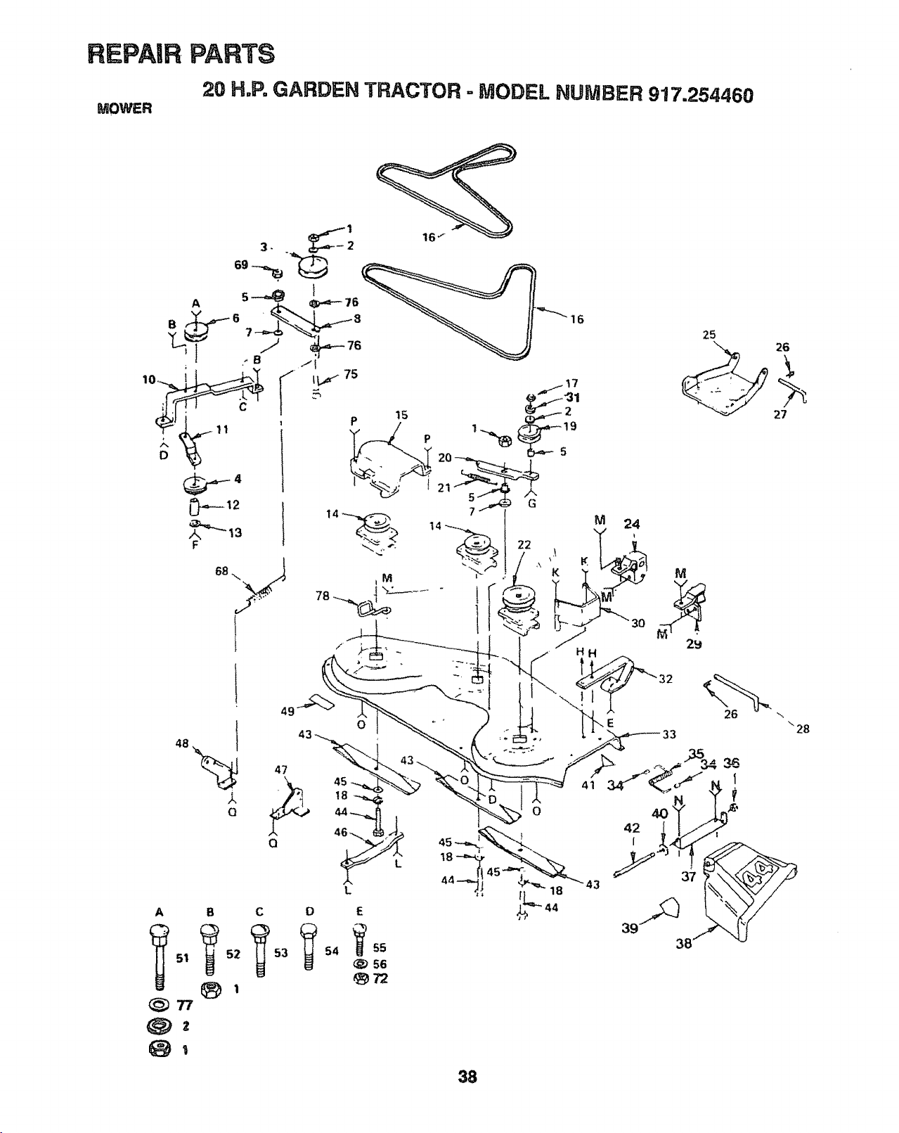
_SJ"
\
C
5_
_2
0
0
5A 56
0

REPAmRPARTS
20 H=P,GARDEN TRACTOR - MODEL NUMBER 917.254460
MOWER
KEY PART DESCRIPTION KEY PART DESCRIPTION
NO. NO. NO. NO.
1 STD541437
2 19131614
3 121316X
4 102403X
5 106902X
6 677A451
7 106513X
8 121425X
10 106523X
11 106522X
12 121236X
13 STD551037
14 121658X
15 106214X
16 106085X
17 STD541037
18 STD551137
19 102932X
20 106526X
21 7644J
22 121705X
24 10651 lX
25 105662X
26 4921H
27 I05744X
28 109835X
29 106512X
30 108119X
31 10040600
32 8418J
33 121423X
34 105304X
35 106734X
36 110452X
37 109743X
38 109785X
39 121343X
Nut - Lock3/8- 16 40 19111016
Washer 13/.32x 1 x 14 Ga. 41
Pulley Idler 42 106735X
Pulley, idler 43 106635X
Spacer 44 STD623715
Pulley Idler 45 19132012
Washer- Wear 46 7631J
Arm- Idler 47 123807X
Bar Support - Idler
Brace- Idler- Deck 48 123808X
Spacer
Washer, 13/32 X 13/16 X 16 49 106223X
Ga.. 51 STD533717
Mandrel- Secondaq/ 52 STD533710
Guard 53 STD533715
V Belt 54 STD523712
Nut, Hex 3/8 - 16 55 STD533107
Washer- Lock 3/8 56 STD551031
Idler- Flat 57 STD541431
Arm- Idler- Deck 58 STD523730
Spring- Extension 59 74110632
Mandrel- Primary 61 19111216
Bracket Lift L,.H,. 62 STD523150
Link Parallel 65 STD533107
Retainer _ Spring
Pin, Front Hinge 66 17490612
Pin, Rear Hinge
Bracket Lift - R.H., 67 STD533707
Guard Belt - R.H_ 68 I02727X
Washer, Lock Hvy., HeL Spring 69 STD541437
Runner- R. H. 70 STD533107
Housing - Mower 72 1685H
Cap Sleeve 75 72140620
Spring 76 19131210
Nut° Push 77 STD533106
Bracket- Deflector 78 !21352X
Guard- Discharge 79 72110505
Decal- Warning .... 125493X
Washer 11/32 x 5/8 x 16 Ga.
Decal OPEl ( not serviced)
Rod Hinge
Blade
* Bolt_ Hex 3/8 - 24 x 1- I/2 Gr, 5
Washer 13/32 x 1-!/4 x 12 Ga,
Runner- L_H_
Bracket Suspension, Rear-
R_H,
Bracket- Suspension, Rear-
L.H.
Decal- V-Belt - Schematic
* Bolt _ Carriage 3/8 - 16 x I - 3/4
" Bolt- Carriage 3/8 _ i6 x 1
* Bolt- Carriage 3/8 16 _ I_i/2
* Bolt- Hex3/8-16x1- 1/4
* Bolt- Carriage 5/16- 18 x 3,'4
* Washer 11/32 x 11/16x 16 Ga,.
* Nut - Lock 5/16- 18
* Bolt- Hex3/8-16x3
Screw- Flat Head 3/8 - 16 x 2
Washer 11/32 x 3/4x 16 Ga.
* Bolt - Hex 5/16 18 x 5
* Bolt - Carriage 5/16 - 18 x 5/8
UNC x 3/4
Screw- Hex Washer Thread
Rolling 3/8 16 x 3/4
* Bolt- Carriage 3/8 - 16 x 3/4
Spring _ Extension
" Nut - Centerlock 3/8 - t6
* Bolt - Carriage 5/16- 18 x 3/4
Nut - Lock 5/16- 18
Bolt, Carriage 3/8- 16 X 2 1/2
Washer 13/32 x 3/4 x 10 Ga.
Washer, 13/32 X 7/8 X 10 Gao
Keeper- L.H Mandrel
* Bolt - Carriage 5/16 _ 18 X 5/8
Mower Deck, Complete
* STANDARD HARDWARE--PURCHASE LOCALLY
H
72
58
G
i' 59
L
79
57
62
M N O P a
61 _ 57 _D 56
57
NOTE: All component dimensions given in US inches-
I inch = 25 4 mm
61
_57
39
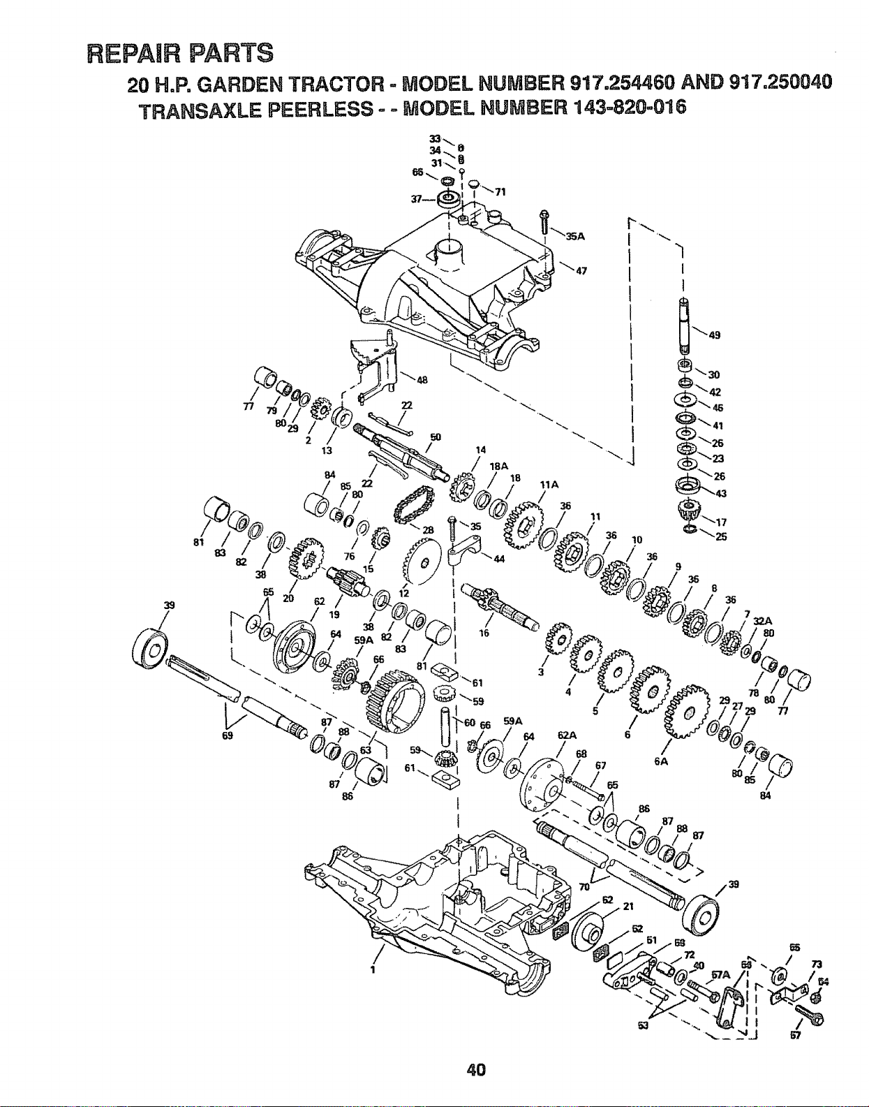
REPAIR PARTS
20 H.P, GARDEN TRACTOR = MODEL NUMBER 917.254460 AND 917.250040
TRANSAXLE PEERLESS- =,MODEL NUMBER 143=820-016
33-.,.
34..,,,8
66 31_" B
",,,.Q
37--
"1
_47
1
]
_'49
/
1
40
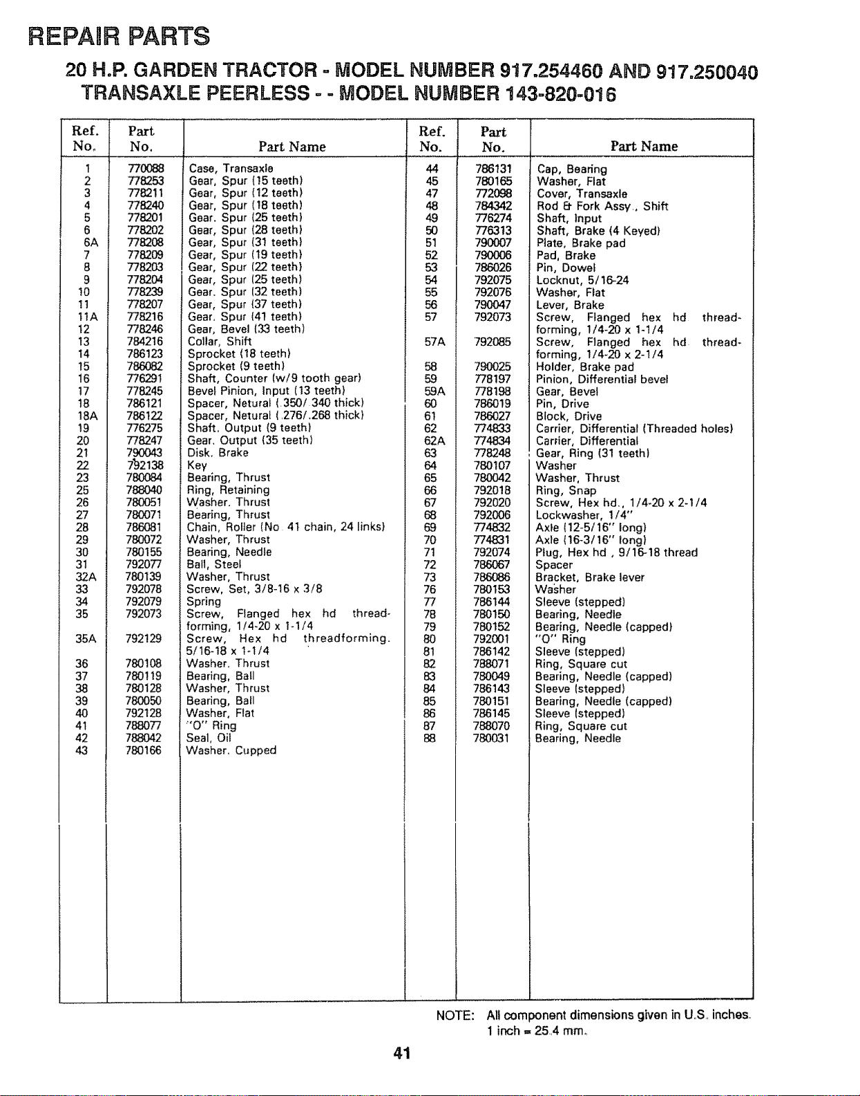
REPAIR PARTS
20 H.P. GARDEN TRACTOR - MODEL NUMBER 917o254460 AND 917o250040
TRANSAXLE PEERLESS - - MODEL NUMBER 143-820-016
Ref.
No.
t
2
3
4
5
6
6A
7
8
9
!0
11
11A
t2
13
14
15
16
t7
t8
18A
t9
20
21
22
23
25
26
27
28
29
30
31
32A
33
34
35
35A
36
37
38
39
40
4t
Part
No.
770088
778253
778211
778240
778201
778202
778208
7782O9
778203
778204
778239
778207
778216
778246
784216
786123
786082
Part Name
Case, Transaxle
Gear, Spur (!5 teeth)
Gear, Spur (12 teeth)
Gear, Spur (18 teeth)
Gear. Spur (25 teeth)
Gear, Spur (28 teeth}
Gear, Spur (31 teeth)
Gear, Spur (19 teeth)
Gear, Spur (22 teeth}
Gear, Spur (25 teeth)
Gear. Spur 132 teeth)
Gear, Spur (37 teeth)
Gear. Spur (41 teeth)
Gear, Bevel (33 teeth)
Collar, Shift
Sprocket (18 teeth)
Sprocket (9 teeth)
Ref.
No.
44
45
47
48
49
5O
51
52
53
54
55
56
57
57A
58
776291
77824-5
786121
786122
776275
778247
790043
7.'92138
780O84
788O4O
780051
780071
786081
780072
780155
792077
780139
792078
792079
792073
792129
780108
780119
780128
780050
792128
788077
788042
780166
Shaft, Counter (w/9 tooth gear)
Bevel Pinion, Input (13 teeth}
Spacer, Neturaf (350/340 thick)
Spacer, Netural (276/.268 thick}
Shaft. Output (9 teeth)
Gear. Output (35 teeth)
Disk. Brake
Key
Bearing, Thrust
Ring, Retaining
Washer. Thrust
Bearing, Thrust
Chain, Roller (No 4t chain, 24 links}
Washer, Thrust
Bearing, Needfe
Ball, Steet
Washer, Thrust
Screw, Set, 3/8-16 x 3/8
Spring
Screw, Flanged hex hd thread-
forming, 1!4-20 x t-1/4
Screw, Hex hd threadforming.
5/16-t8 x 1-t/4
Washer. Thrust
Bearing, Ball
Washer, Thrust
Bearing, Ball
Washer, Flat
"0" Ring
Seal, Oil
Washer. Cupped
59
59A
6O
61
62
62A
63
64
65
66
67
68
69
70
71
72
73
76
77
78
79
8O
81
82
83
84
85
86
87
88
Part
No.
786131
780165
772O98
784342
776274
776313
790007
790OO6
786026
792075
792076
790047
792073
792O85
790025
778197
778198
786019
786027
774833
774834
778248
780107
780042
792018
792020
792006
774832
774831
792074
786067
786088
780153
786144
780150
780152
792001
786142
788071
780049
786143
780151
786145
788070
780031
NOTE:
Part Name
Cai Beadng
Washer, Flat
Co Transaxle
Re 6_ Fork Assy, Shift
Sh Input
Sh Brake (4 Keyed)
Pla Brake pad
Pa{ Brake
Pin Dowel
Locknut, 5/16-24
Washer, Flat
Le\ Brake
Scl Flanged hex hd thread-
forming, I/4-20 x 1-1/4
Scl Ranged hex hd thread-
forming, 1/4-20 x 2-1/4
Holder, Brake pad
Pin Differential bevel
Ge_ Bevel
Pin Drive
Blo Drive
Carrier, Differential (Threaded holes}
Carrier, Differential
Ge_ , Ring (31 teeth)
Washer
Washer, Thrust
Rin Snap
Sc_ Hex hd., 1/4-20 x 2-1/4
Lockwasher, 1/4"
Axl (12-5/16" long)
Axl (16-3/16" long}
Ptu Hex hd, 9/16-18 thread
Spacer
Bracket, Brake lever
Wa
Sle (stepped)
Bearing, Needle
Bearing, Needle (capped)
"O' Ring
Sle (stepped)
Rin Square cut
Bearing, Needle (capped)
Sle (stepped)
Bearing, Needle (capped)
Sle Istepped)
Rin Square cut
Bearing, Needte
i
i
=
All component dimensions given in U.S inches.
1 inch ,, 254 mine
41
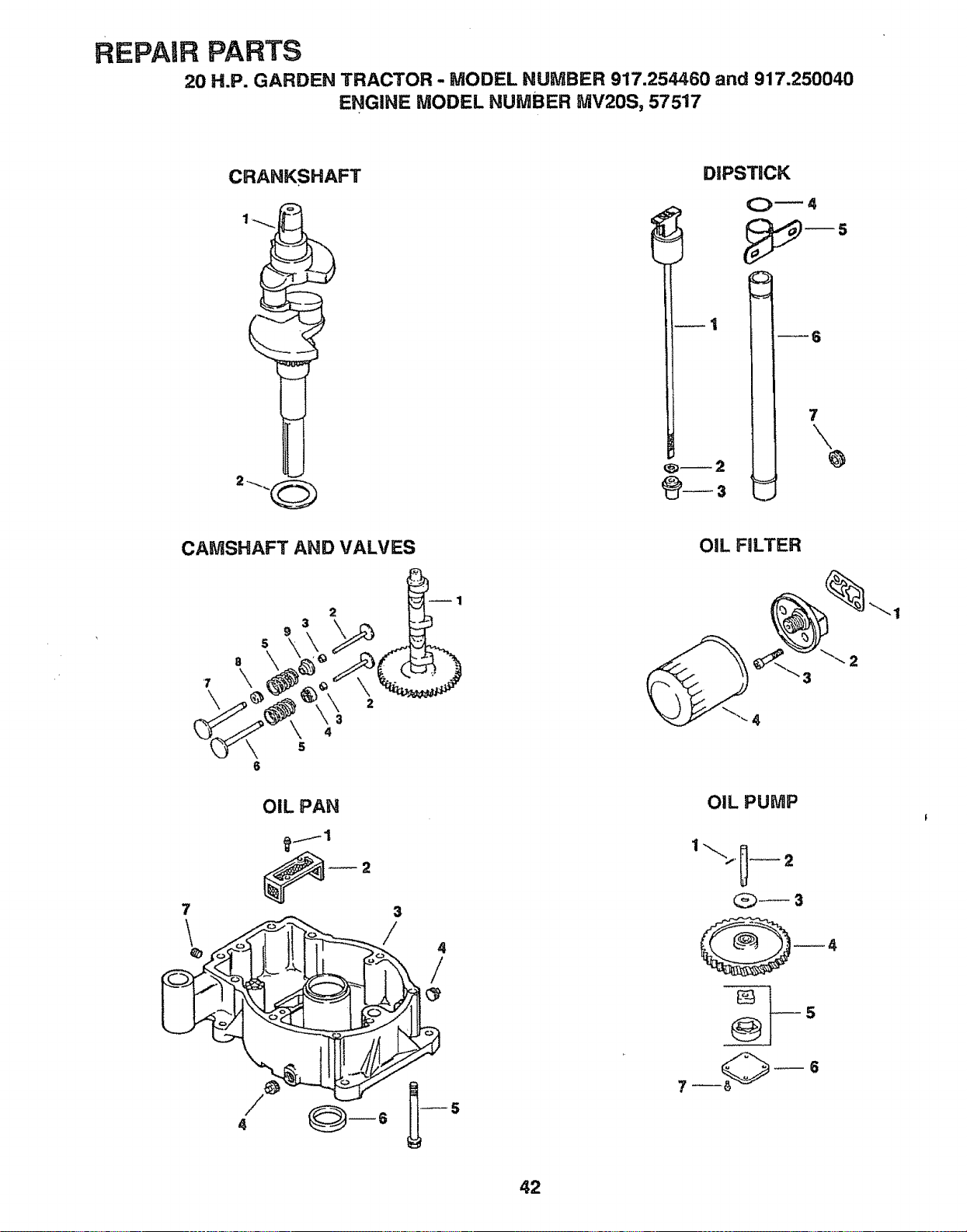
REPAIR PARTS
20 H.P. GARDEN TRACTOR - MODEL NUMBER 917.254460 and 917.250040
ENGINE MODEL NUMBER MV20S, 57517
CRANKSHAFT
DIPSTICK
_6
7
\
v
CAMSHAFT AND VALVES
2
7
OIL PAN
2
3
/
4
4
/
OiL FILTER
OIL PUMP
@_3
"'-1
42
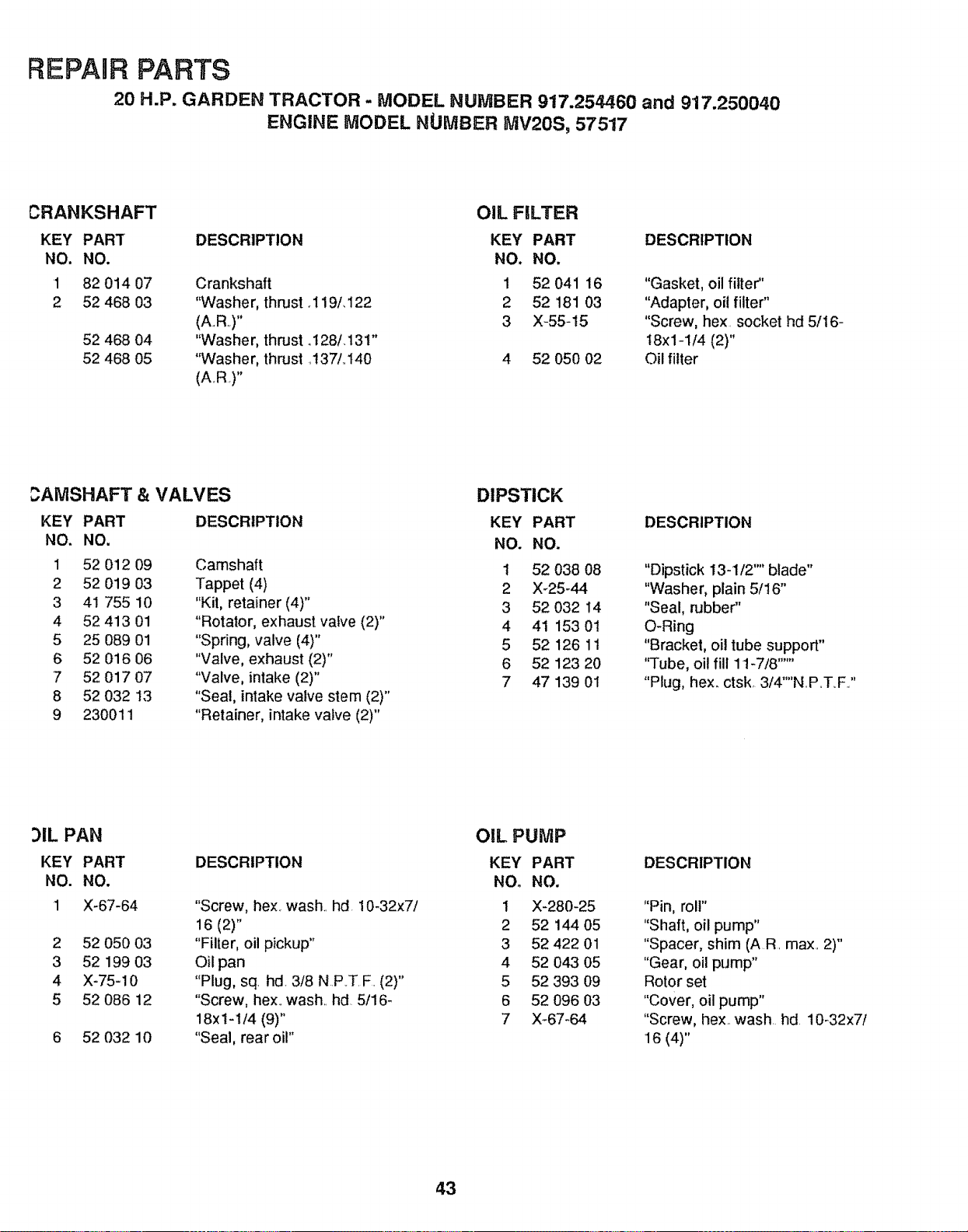
REPAUB PARTS
20 H.P. GARDEN TRACTOR - MODEL NUMBER 917.254460 and 917.250040
ENGINE MODEL NUMBER MV20S, 57517
CRANKSHAFT OIL FILTER
KEY PART DESCRIPTION KEY PART
NO. NO. NO. NO.
1 82 014 07 Crankshaft 1 52 041 16 "Gasket, oil filter"
2 52 468 03 "Washer, thrust.119i.122 2 52 181 03 "Adapter, oil filter"
(AR.)" 3 X-55-15 "Screw, hex. socket hd 5/16-
52 468 04 "Washer, thrust .128/.13t" t8x1-1/4 (2)"
52 468 05 "Washer, thrust .137/,.140 4 52 050 02 Oil filter
(A..R.)"
DESCRIPTION
3ANISHAFT & VALVES DIPSTICK
KEY PART DESCRIPTION KEY PART DESCRIPTION
NO. NO. NO. NO.
1 52 012 09 Camshaft 1 52 038 08 "Dipstick 13-1/2"" blade"
2 52 019 03 Tappet (4) 2 X-25-44 "Washer, plain 5/16"
3 41 755 10 "Kit, retainer (4)" 3 52 032 14 "Seal, rubber"
4 52 413 01 "Rotator, exhaust valve (2)" 4 41 153 01 O-Ring
5 25 089 01 "Spring, valve (4)" 5 52 126 11 "Bracket, oi! tube support"
6 52 016 06 "Valve, exhaust (2)" 6 52 123 20 '%ube, oil fill 11-7/8 ......
7 52 017 07 "Valve, intake (2)" 7 47 139 01 "Plug, hex_ ctsk, 3/4'"'NP.T_F.."
8 52 032 13 "Seat, intake valve stem (2)"
9 230011 "Retainer, intake valve (2)"
)IL PAN
KEY PART
NO. NO.
I X-67-64
2 52 050 03
3 52 199 03
4 X-75-10
5 52 086 12
6 52 032 10
OIL PUMP
DESCRIPTION KEY PART
NOo NO.
"Screw, hex, wash., hd. 10-32x7/ 1 X-280-25
16 (2)" 2 52 144 05
"Filler, oil pickup" 3 52 422 01
Oil pan 4 52 04.3 05
"Plug, sq hd. 3/8 N.RT.F. (2)" 5 52 393 09
"Screw, hex,. wash., hd 5/16- 6 52 096 03
18x1-1/4 (9)" 7 X_67-64
"Seal, rear oil"
DESCRIPTION
"Pin, roll"
"Shaft, oil pump"
"Spacer, shim (A R. max.. 2)"
"Gear, oil pump"
Rotor set
"Cover, oil pump"
"Screw, hex,. wash. hd 10-32x7/
16 (4)"
43
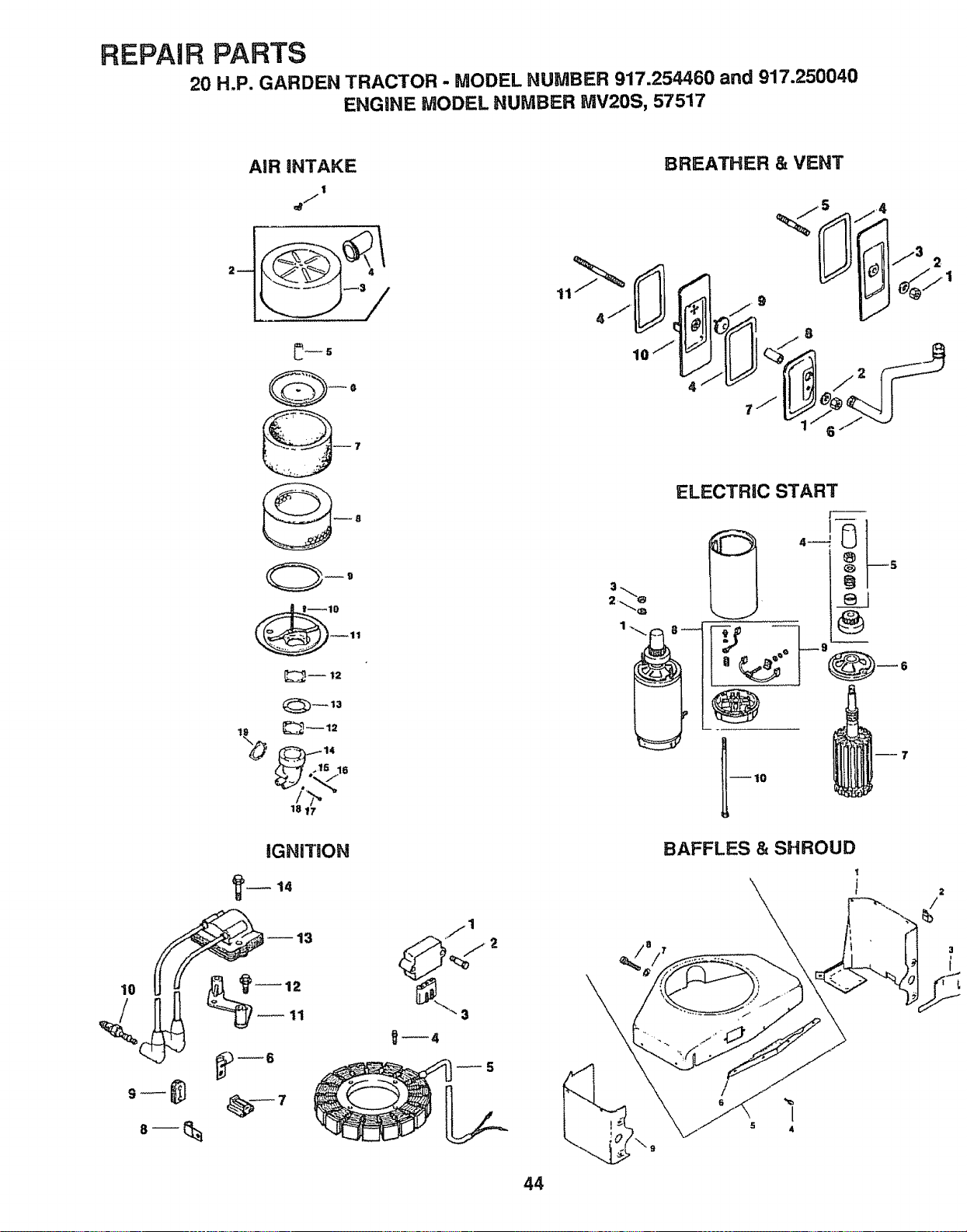
REPAIR PARTS
20 H.P. GARDEN TRACTOR - MODEL NUMBER 917.254460 and 917.250040
ENGINE MODEL NUMBER MV20S, 57517
AiR iNTAKE
I
BREATHER & VENT
IL !!_1_/3 2
18 17
iGNiTiON
_12
_11
,,71
_4
44
ELECTRIC START
BAFFLES & SHROUD
t
2
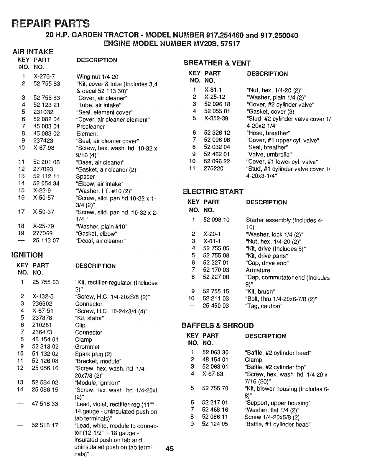
REPAUR PARTS
20 H.P. GARDEN TRACTOR., MODEL NUMBER 917,254460 and 917.250040
ENGINE MODEL NUMBER MV20S, 57517
AIR INTAKE
KEY PART
NO, NO,
1 X-276-7
2 52 755 83
3 52 755 83
4 52 123 21
5 231032
6 52 082 04
7 45 083 01
8 45 083 02
9 237423
10 X-67-98
11 52 20t 06
12 277093
13 52 112 11
14 52 054 34
15 X-22-9
16 X-50-57
17 X-50-37
18 X-25-79
19 277069
25 113 07
IGNITION
KEY PART
NO, NO,
1 25 755 03
2 X-132-5
3 236602
4 X-67-5t
5 237878
6 210281
7 236473
8 48 t54 01
9 52 313 02
10 51 132 02
11 52 126 08
12 25 086 16
13 52 584 02
14 25 086 15
-- 47 518 33
-- 52 518 17
DESCRIPTION
BREATHER & VENT
DESCRIPTION
"Kit, rectifier-regulator (Includes
2)"
"Screw, H C 1/4-20xS/8 (2)"
Connector
"Screw, H C 10-24x3/4 (4)"
"Kit, stator"
Clip
Connector
Clamp
Grommet
Spark plug (2)
"Bracket, module"
"Screw, hex. wash hd t/4-
20x7/8 (2)"
"Module, ignition"
"Screw, hex wash hd. !/4°20xl
(2)"
"Lead, violet, rectifier-reg.(11 '"' -
14 gauge - uninsulated push on
tab terminals)"
"Lead, white, module to connec-
tor (t2-1/2'' - 18 gauge
insulated push on tab and
uninsulaled push on tab termi-
nals)"
KEY PART
Wing nut t/4-20 NO. NO.
"Kit, cover & tube (Includes 3,4
& decal 52 t t3 30)" 1 X-81-1
"Cover, air cleaner" 2 X-25-12
"Tube, air intake" 3 52 096 18
"Seal, element cover" 4 52 055 01
"Cover, air cleaner element" 5 X-352_39
Precleaner
Element 6 52 326 12
"Seal, air cleaner cover" 7 52 096 08
"Screw, hex wash. hd_ 10-32 x 8 52 032 04
9/16 (4)" 9 52 462 01
"Base, air cleaner" 10 52 096 22
"Gasket, air cleaner (2)" 11 275220
Spacer
"Elbow, air intake"
"Washer, I.T. #!0 (2)" ELECTRIC START
"Screw, slid. pan hd:10-32 x 1- KEY PART
3/4 (2)"
"Screw, slid. pan hd 10-32 x 2- NO. NO.
1/4" 1 52 098 10
"Washer, plain #10"
"Gasket, elbow" 2 X-20-1
"Decal, air cleaner" 3 X-81-1
4 52 755 O5
5 52 755 08
6 52 227 01
7 52 170 03
8 52 227 08
9 52 755 15
10 52 211 03
-- 25 450 03
45
DESCRIPTION
"Nut, hexo 1/4-20 (2)"
"Washer, plain 1/4 (2)"
"Cover, #2 cylinder valve"
"Gasket, cover (3)"
"Stud, #2 cylinder valve cover 1/
4-20x2-1/4"
"Hose, breather"
"Cover, #1 upper cyl valve"
"Seal, breather"
"VaIve, umbrella"
"Cover, #1 lower cyt valve"
"Stud, #1 cylinder valve cover 1/
4-20x3-1/4"
DESCRIPTION
Starter assembly (includes 4-
lO)
"Washer, lock 1/4 (2)"
"Nut, hex. 1/4-20 (2)"
"Kit, drive (Includes 5)"
"Kit, drive parts"
"Cap, drive end"
Armature
"Cap, commutator end (Includes
9)"
"Kit, brush"
"Bolt, thru 1/4-20x6-7/8 (2)"
"Tag, caution"
BAFFELS &
KEY PART
NO. NO.
1 52 063 30
2 48 154 01
3 52 063 01
4 X-67-83
5 52 755 70
6 52 217 01
7 52 46816
8 52 086 11
9 52 124 05
SHROUD
DESCRIPTION
"Baffle, #2 cylinder head"
Clamp
"Baffle, #2 cylinder top"
"Screw, hex wash. hd 1/4-20 x
7/16 (20)"
"Kit, blower housing (Includes 6-
8)"
"Support, upper housing"
"Washer, flat 1/4 (2)"
Screw 1/4-20x5/8 (2)
"Baffle, #1 cylinder head"
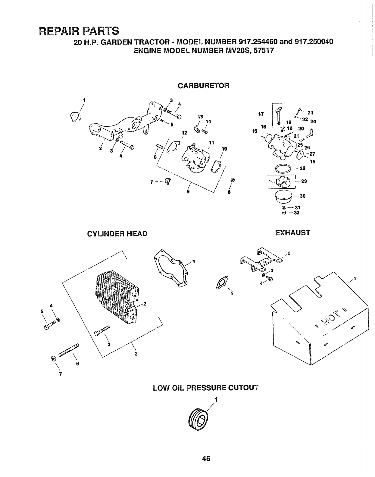
REPAIR PARTS
20 H.P. GARDEN TRACTOR - MODEL NUMBER 917.254460 and 917.250040
ENGINE MODEL NUMBER MV20S, 57517
1
/
CARBURETOR
""" 8
@
[
15
,,__ Z--23
,6 !_. TM ...._,,2,
(_,. _>,).2s2e
15
,- 28
-- 30
_=- 31
6 -- 32
CYLINDER HEAD
EXHAUST
._//t/X' _.fl
.,2
\
7
6
LOW OIL PRESSURE CUTOUT
1
.2
46
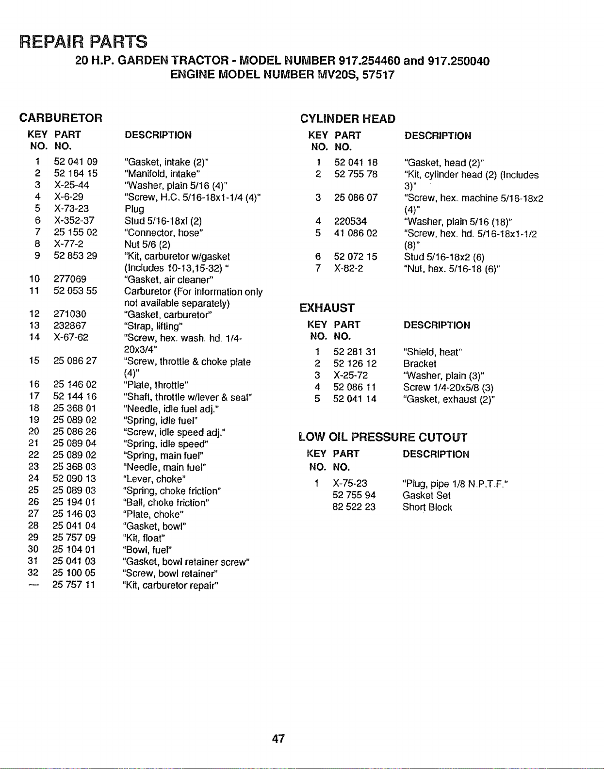
REPAIR PARTS
20 H.P. GARDEN TRACTOR - MODEL NUMBER 917.254460 and 917.250040
ENGINE MODEL NUMBER MV20S, 57517
CARBURETOR CYUNDER HEAD
KEY PART DESCRIPTION KEY PART DESCRIPTION
NO. NO. NO. NO.
1 52 041 09 "Gasket, intake (2)" 1 52 041 18 "Gasket, head (2)"
2 52 164 t5 "Manifold, intake" 2 52 755 78 "Kit, cylinder head (2) (includes
3 X-25-44 "Washer, plain 5/16 (4)" 3)"
4 X-6-29 "Screw, HCo 5/16-18x1-1/4 (4)" 3 25 086 07 "Screw, hex. machine 5/16-18x2
5 X-73-23 Plug (4)"
6 X-352-37 Stud 5/16-18xi (2) 4 220534 "Washer, plain 5/16 (18)"
7 25 155 02 "Connector, hose" 5 41 086 02 "Screw, hex_ hal. 5/16-18xl q /2
8 X-77-2 Nut 5/6 (2) (8)"
9 52 853 29 "Kit, carburetor w/gasket 6 52 072 15 Stud 5/16-18x2 (6)
(Includes 10-13,15-32)" 7 X-82-2 "Nut, hexo 5/16-18 (6)"
10 277069
11 52 053 55
12 271030
13 232867
t4 X-67-62
15 25 086 27
16 25 146 02
17 52 14416
18 25 36801
19 25 089 02
20 25 086 26
21 25 089 04
22 25 089 02
23 25 368 03
24 52 090 13
25 25 O89 03
26 25 194 0I
27 25 146 03
28 25 041 04
29 25 757 09
30 25 104 01
31 25 041 03
32 25 100 05
25 757 11
"Gasket, air cleaner"
Carburetor (For information only
not available separately)
"Gasket, carburetor"
"Strap, lifting"
"Screw, hex, wash. hd 1/4-
20x3/4"
"Screw, throttle & choke plate
(4)"
"Plate, throttle"
"Shaft, throttle w/lever & seal"
"Needle, idle fuel adj.."
"Spring, idle fuel"
"Screw, idle speed adj.,"
"Spring, idle speed"
"Spring, main fuel"
"Needle, main fuel"
"Lever, choke"
"Spring, choke friction"
"Ball, choke friction"
"Plate, choke"
"Gasket, bowl"
"Kit, float"
"Bowl, fuel"
"Gasket, bowl retainer screw"
"Screw, bowl retainer"
"Kit, carburetor repair"
EXHAUST
KEY PART DESCRIPTION
NO. NO.
1 52 281 31 "Shield, heat"
2 52 126 12 Bracket
3 X-25-72 "Washer, plain (3)"
4 52 086 11 Screw 1/4-20x5/8 (3)
5 52 041 14 "Gasket, exhaust (2)"
LOW OiL PRESSURE CUTOUT
KEY
NO.
1
PART DESCRIPTION
NO,
X-75-23 "Plug, pipe t/8 NPoTF.."
52 755 94 Gasket Set
82 522 23 Short Block
47
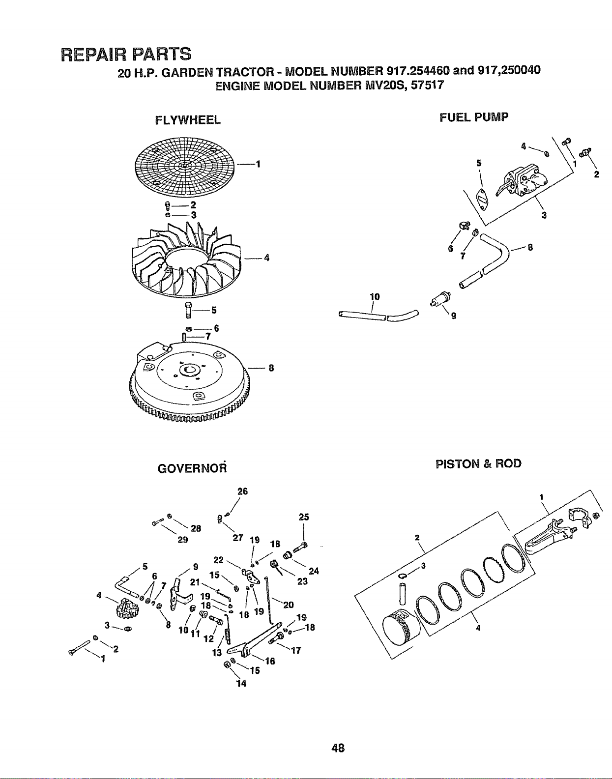
REPAIR PARTS
20 H.P. GARDEN TRACTOR - MODEL NUMBER 917.254460 and 917,250040
ENGINE MODEL NUMBER MV20S, 57517
FLYWHEEL
_--2
e_3
_4
FUEL PUMP
S
\
3
2
10
GOVERNOF_
26
/
_, "_ 25
29 27 i_ 18
s'/ 6 / 15-- % - -_'"- "24
_'_ t 5
14
PISTON & ROD
48
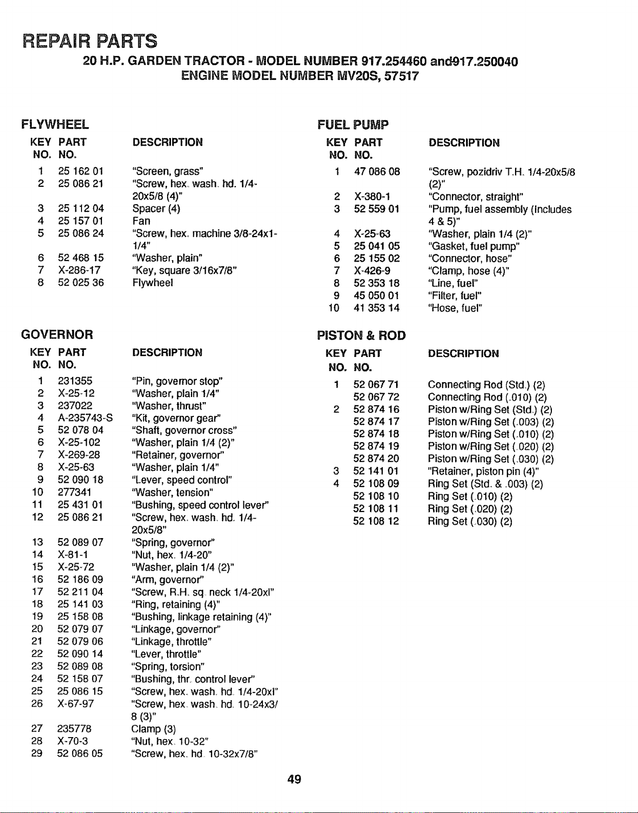
REPAIR PARTS
20 H.P. GARDEN TRACTOR - _ODEL NUMBER 917.254460 and917.250040
ENGINE MODEL NUMBER MV20S, 57517
FLYWHEEL
KEY PART
NO. NO.
1 25 162 01
2 25 086 21
3 25 112 04
4 25 157 01
5 25 086 24
6 52 468 15
7 X-286-17
8 52 025 36
GOVERNOR
KEY PART
NO. NO.
1 231355
2 X-25-12
3 237022
4 A-235743-S
5 52 O78 O4
6 X-25-102
7 X-269-28
8 X-25-63
9 52 090 18
10 277341
11 25 431 01
12 25 086 21
13 52 089 07
14 X-81-1
15 X-25-72
t6 52 186 09
t7 52 21! 04
18 25141 03
19 25 t58 08
20 52 079 07
21 52 079 06
22 52 090 14
23 52 089 08
24 52 158 07
25 25 086 15
26 X_67-97
27 235778
28 X-70-3
29 52 086 05
DESCRIPTION
"Screen, grass"
"Screw, hex,. wash., hd. 1/4-
20x5!8 (4)"
Spacer (4)
Fan
"Screw, hexo machine 3/8-24xl-
114"
"Washer, plain"
"Key, square 3!16x7/8"
Flywheel
DESCRIPTION
"Pin, governor stop"
"Washer, plain 1/4"
"Washer, thnJst"
"Kit, governor gear"
"Shaft, governor cross"
"Washer, plain 1/4 (2)"
"Retainer, governor"
"Washer, plain 114"
"Lever, speed contro!"
"Washer, tension"
"Bushing, speed control lever"
"Screw, hex. wash hd. 1/4-
20x518"
"Spring, governor"
"Nut, hex. 1/4-20"
"Washer, plain 114(2)"
"Arm, governor"
"Screw, R_H..sq. neck I/4-20x1"
"Ring, retaining (4)"
"Bushing, linkage retaining (4)"
"Linkage, governor"
"Linkage, throttle"
"Lever, throttle"
"Spring, torsion"
"Bushing, thr.. control lever"
"Screw, hexo wash., hd. 114-20x1"
"Screw, hex. wash hd. 10-24x3/
8 (3)"
Clamp (3)
"Nut, hex. !0-32"
"Screw, hex.. hd. 10-32x7!8"
FUEL PUMP
KEY PART
NO. NO.
1 47 086 08
2 X-380-1
3 52 559 01
4 X-25-63
5 25 041 05
6 25 155 02
7 X-426_9
8 52 353 18
9 45 050 01
10 41 353 14
PISTON & ROD
KEY PART
NO. NO.
1 52 067 71
52 067 72
2 52 874 16
52874 17
52 874 18
52 874 19
52 874 20
3 52 141 01
4 52 108 09
52 108 10
52 108 11
52 108 12
49
DESCRIPTION
"Screw, pozidriv T,H, 1/4-20x5/8
(2)"
"Connector, straight"
"Pump, fuel assembly (Includes
4 &5)"
"Washer, plain 1/4 (2)"
"Gasket, fuel pump"
"Connector, hose"
"Clamp, hose (4)"
"Line, fuel"
"Filter, fuel"
"Hose, fuel"
DESCRIPTION
Connecting Rod (Std,) (2)
Connecting Rod (.010) (2)
Piston wiRing Set (Std,) (2)
Piston w/Ring Set (.003) (2)
Piston wiring Set (.010) (2)
Piston wiring Set (.020) (2)
Piston wiring Set (.030) (2)
"Retainer, piston pin (4)"
Ring Set (Std_ & ..003) (2)
Ring Set (.O10) (2)
Ring Set (.020) (2)
Ring Set (,.030) (2)
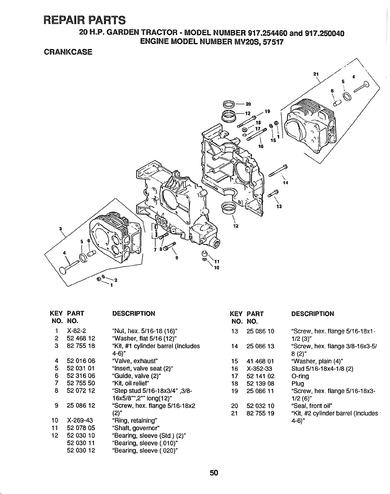
REPAIR PARTS
20 H.P. GARDEN TRACTOR - MODEL NUMBER 917,254460 and 917.250040
ENGINE MODEL NUMBER MV20S, 57517
CRANKCASE
21 _ 4
14
3
5
4
\
\
12
\
13
KEY
NO.
i
2
3
4
5
7
8
10
11
12
PART
NO.
X-82-2
52 468 12
82 755 18
52 016 06
52 031 01
52 316 06
52 755 50
52 072 12
25 086 12
X-269-43
52 078 05
52 030 10
52 030 11
52 030 12
DESCRIPTION
"Nut, hex.. 5/16d8 (16)"
"Washer', flat 5/16 (12)"
"Kit, #1 cylinder barrel (Includes
4-6)"
"Valve, exhaust"
"Insert, valve seat (2)"
"Guide, valve (2)"
"Kit, oil relief"
"Step stud 5/16-18x3/4" ,3/8-
16x5/8"",2"" long(12)"
"Screw, hexo flange 5/16-18x2
(2)"
"Ring, retaining"
"Shaft, governor"
"Bearing; sleeve (Std.) (2)"
"Bearing, sleeve (_010)"
"Bearing, sleeve (.020)"
KEY PART
NO. NO.
13 25 086 10
14 25 086 13
15 41 46801
16 X-352-33
17 52 141 02
18 52 139 08
19 25 086 11
20 52 032 10
21 82 755 19
DESCRIPTION
"Screw, flex. flange 5/16-18×1-
1f2 (3)"
"Screw, hex. flange 3/8-16x3-5I
8 (2)"
"Washer, plain (4)"
Stud 5/16-18x4-1/8 (2)
O-ring
Plug
"Screw, hex_ flange 5/16-18x3-
1/2 (6)"
"Seal, front oil"
"Kit, #2 cylinder barrel (includes
4-6)"
5O

SERVICE NOTES
51

SERVICE NOTES
52
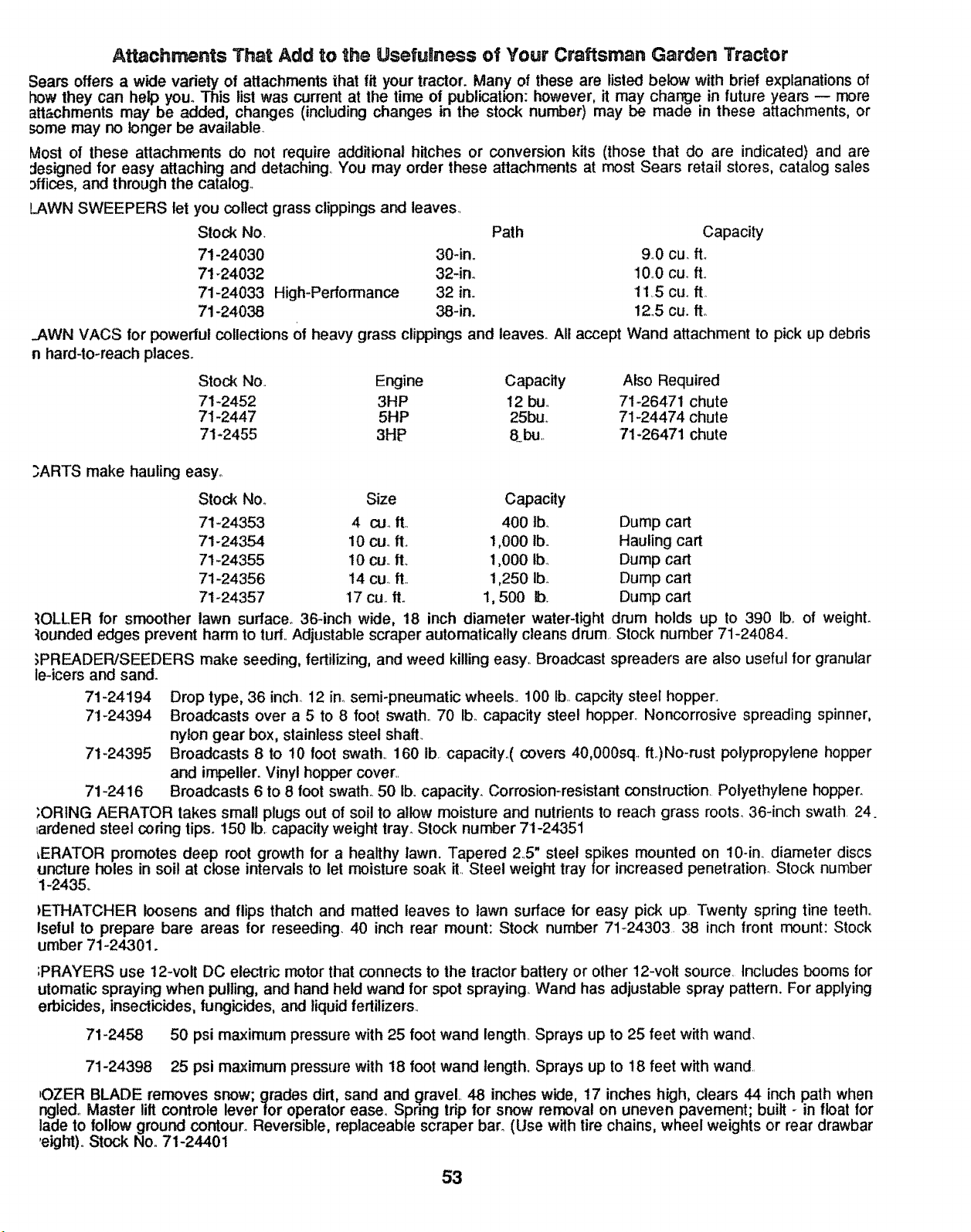
Attachments That Add to the UsefuRness of Your Craftsman Garden Tractor
Sears offers a wide variety of attachments that fit your tractor. Many of these are listed below with brief explanations of
_w they can help you. This list was current at the time of publication: however, it may change in future years -- more
atl_=chmentsmay be added, changes (including changes in the stock number) may be made in these attachments, or
some may no longer be available.
Most of these attachments do not require additional hitches or conversion kits (those that do are indicated) and are
:lesigned for easy attaching and detaching. You may order these attachments at most Sears retail stores, catalog sales
3ffices, and through the catalog°
LAWN SWEEPERS let you collectgrass clippings and leaves..
Stock Nov Path Capacity
71-24030 30-in.. 940 cu. fL
71_24032 32-in_ 1Q10cur ft..
71-24033 High-Performance 32 in. 115 cuo ft
71-24038 38-in. 12.5 cu. fto
.AWN VACS for powerful collections Of heavy grass clippings and leaves. All accept Wand attachment to pick up debris
n hard-to-reach places.
Stock No.. Engine Capacity Also Required
71-2452 3HP 12 bu.. 71-26471 chute
71-2447 5HP 25bu,. 71-24474 chute
71-2455 3HP 8bu.. 71-26471 chute
.3ARTS make hauling easy°
Stock Nov Size Capacity
71-24353 4 cur ft., 400 Ibm Dump cart
71-24354 10 cu..ft.. 1,000 lb. Hauling cart
71-24355 10 cu.. fL 1,000 Ibm Dump cart
71-24356 14 cu.. ft.. 1,250 lbo Dump cart
71-24357 17 cu.. fro 1,500 lb. Dump cart
:_OLLER for smoother lawn surface.. 36-inch wide, 18 inch diameter water-tight drum holds up to 390 Ibo of weighL
_ounded edges prevent harm to turf.. Adjustable scraper automatically cleans drum. Stock number 71-24084..
;PREADEPJSEEDERS make seeding, fertilizing, and weed killing easy.. Broadcast spreaders are also useful for granular
Drop type, 36 inch. 12 in..semi-pneumatic wheels.. 100 Ib..capc_y' steel hopper..
Broadcasts over a 5 to 8 foot swath. 70 Ib. capacity steel hopper. Noncorrosive spreading spinner,
nylon gear box, stainless steel shaft_
71-24395 Broadcasts 8 to 10 foot swath. 160 Ib. capacity..( covers 40,000sq, ft.)No-nJst polypropytene hopper
and impeller. Vinyl hopper cover_.
71-2416 Broadcasts 6 to 8 foot swath° 50 lb..capacity. Corrosion-resistant construction. Polyethylene hopper.
;ORtNG AERATOR takes small plugs out of soil to allow moisture and nutrients to reach grass roots_ 36-inch swath 24.
_ardened steel coring tips. 150 lb. capacity weight tray.. Stock number 7I-24351
_ERATOR promotes deep root growth for a healthy lawn. Tapered 25" steel spikes mounted on 10-in. diameter discs
uncture holes in soil at close intervals to let moisture soak it.. Steel weight tray for increased penetration. Stock number
1-2435.
le-icers and sand.
71-24194
71-24394
)E-THATCHER loosens and flips thatch and matted leaves to lawn surface for easy pick up. Twenty spring tine teeth.
lselul to prepare bare areas for reseeding 40 inch rear mount: Stock number 71_24303. 38 inch front mount: Stock
umber 71-24.301.
;PRAYERS use 12-volt DC electric motor that connects to the tractor battery or other 12-volt source. Includes booms for
utomatic spraying when pulling, and hand held wand for spot spraying Wand has adjustable spray pattern. For applying
erbicides, insecticides, fungicides, and liquid fertilizers.
71-2458 50 psi maximum pressure with 25 foot wand length. Sprays up to 25 feet with wand.
71-24398 25 psi maximum pressure with 18 foot wand length. Sprays up to 18 feet with wand..
tOZER BLADE removes snow; grades dirt, sand and QraveL 48 inches wide, 17 inches high, clears 44 inch path when
ngled_ Master lift controle lever for operator ease.. Spnng trip for snow removal on uneven pavement; built - in float for
!ade to follow ground contour. Reversible, replaceable scraper bar_ (Use with tire chains, wheel weights or rear drawbar
eight)° Stock No.. 71-24401
53
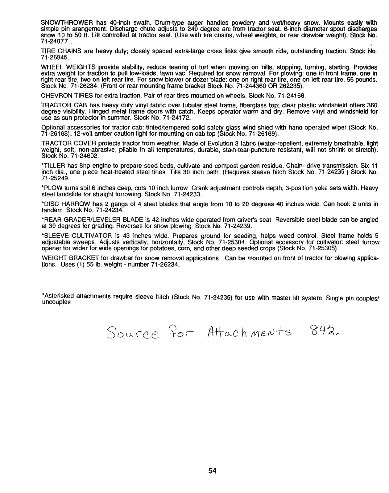
SNOWTHROWER has 40-inch swath. Drum-type auger handles powdery and wet/heavy snow. Mounts easily with
simple pin arangement_ Discharge chute adjusts to 240 degree arc from tractor seat 6-inch diameter spout discharges
snow 10 to 50 ft. Lift controlled at tractor seat. (Use with tire chains, wheel weights, or rear drawbar weight). StockNo.
71-24077
r
TIRE CHAINS are heavy duty; closely spaced extra-large cross links give smooth ride, outstanding traction. Stock No.
71-26945_
WHEEL WEIGHTS provide stability, reduce tearing of tuff when moving on hills, stopping, turning, starting. Provides
extra weight for traction to pull low-loads, lawn vac. Required for snow removal For plowing: one in front frame, one in
right rear tire, two on left rear tire. For snow blower or dozer blade: one on right rear tire, one on left rear tire. 55 pounds,
Stock No. 71_26234. (Front or rear mounting frame bracket Stock No. 71-244360 OR 262235).
CHEVRON TIRES for extra traction. Pair of rear tires mounted on wheels Stock No_ 7t-24166.
TRACTOR CAB has heavy duty vinyl fabric over tubular steel frame, fiberglass top; clear plastic windshield offers 360
degree visibility. Hinged metal frame doors with catch. Keeps operator warm and dry Remove vinyl and windshield for
use as sun protector in summer. Stock Noo 71-24172.
_tional accessories for tractor cab: tinted/tempered solid safety glass wind shied with hand operated wiper (Stock No.
71-26t68); 12-vott amber caution light for mounting on cab top (Stock No 71-26169).
TRACTOR COVER protects tractor from weather Made of Evolution 3 fabric (water-repellent, extremely breathable, light
weight, soft, non-abrasive, pliable in all temperatures, durable, stain-tear-puncture resistant, wilt not shrink or stretch).
Stock No_7!-24602.
"TILLER has 8hp engine to prepare seed beds, cultivate and compost garden residue, Chain- drive transmission_ Six 1t
inch diao, one piece heat-treated steel tines.. Tills 30 inch path (Requires sleeve hitch Stock No. 71-24235 ) Stock No,.
71-25249.
*PLOW turns soil 6 inches deep, cuts 10 inch furrow. Crank adjustment controls depth, 3-position yoke sets width. Heavy
steel landslide for straight forrowing. Stock No. 71-24233.
"DISC HARROW has 2 gangs of 4 steel blades that angle from I0 to 20 degrees 40 inches wide., Can hook 2 units in
tandem. Stock No.. 71-24234,.
*REAR GRADER/LEVELER BLADE is 42-inches wide operated from driver's seal Reversible steel blade can be angled
at 30 degrees for grading. Reverses for snow plowing._ Stock No., 71-24239_
*SLEEVE CULTIVATOR is 43 inches wide.. Prepares ground for seeding, helps weed control. Steel frame holds 5
adjustable sweeps. Adjusts vertically, horizontally, Stock No. 71-25304. Optional accessory for cultivator: steel furrow
opener for wider for wide openings for potatoes, corn, and other deep seeded crops (Stock No_ 71-25305).
WEIGHT BRACKET for drawbar for snow removal applications.. Can be mounted on front of tractor for plowing applica-
tions_ Uses (t) 55 lb. weight- number 71-26234_
*Asterisked attachments require sleeve hitch (Stock No.. 71-24235) for use with master lift system Single pin couples/
uncouples..
54

SUGGESTED GUIDE FOR SIGHTING SLOPES FOR SAFE OPERATION
O'1
SiGHTiNG
GUIDE
ONLY RiDE UP AND DOWN HILL,
NOT ACROSS HILL
SIGHT AND HOLD THiS LEVEL WiTH
SKY LiNE OR TREE.
d
,_, Operate your Tractor up and down the face of slopes (not t
_ greater than 15°) never across the face. Make turns gradu- j
_1_ ally to prevent tlpping or toss of control. Exercise extreme n
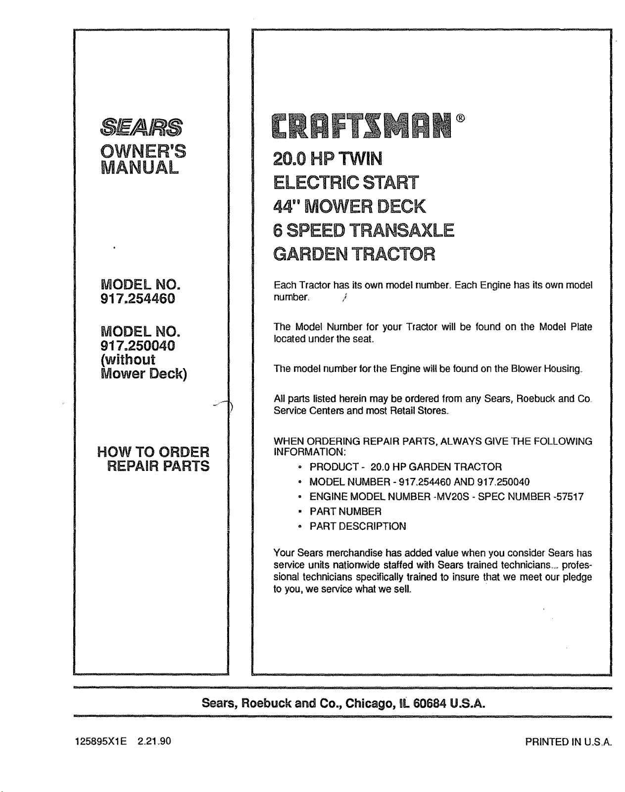
MODEL NO.
917,254460
MODEL NO.
917.250040
(without
Mower Deck)
HOW TO ORDER
REPAIR PARTS
®
20.0 HP TWIN
ELECTRUCSTART
44" MOWER DECK
8 SPEED TRANSAXLE
GARDEN TRACTOR
Each Tractor has its own model number.. Each Engine has its own model
number, ?
The Model Number for your Tractor will be found on the Model Plate
located under the seal
Tile model number Ior tile Engine will be found on the Blower Housing.
All parts listed herein may be ordered from any Sears, Roebuck and Co..
Service Centers and most Retail Stores.
WHEN ORDERING REPAIR PARTS, ALWAYS GIVE THE FOLLOWING
INFORMATION:
o PRODUCT - 20.0 HP GARDEN TRACTOR
• MODEL NUMBER - 917.254460 AND 917.250040
= ENGINE MODEL NUMBER -MV20S - SPEC NUMBER -57517
, PART NUMBER
- PART DESCRIPTION
Your Sears merchandise has added value when you consider Sears has
service units nationwide staffed with Sears trained technicians... _rofes-
sional technicians specifically trained to insure that we meet our pledge
to you, we service what we sell.
• i
Sears, Roebuck and Co., Chicago, UL60684 U.S.A.
125895X1E 2.21_90 PRINTED IN U.SA.


