
NZ AU
Installation instructions
and User guide
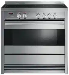
Freestanding cooker
OR90SDBSIPX models


1
Contents
Safety and warnings
2
Installation instructions
8
First use
18
Setting the clock
19
Using your oven
21
Cooking functions
24
Cooking guide
26
Using the rotisserie
28
Using the electronic timer
30
Automatic cooking
31
Induction cooktop introduction
32
Choosing the right cookware
34
Using your induction cooktop
36
Using your cooktop’s special features
37
Cooking guidelines
39
Care and cleaning
40
Using the Self clean function
54
Cooktop fault codes
56
Troubleshooting
57
Warranty and service
59
Important!
SAVE THESE INSTRUCTIONS
The models shown in this User Guide may not be available in all markets and are
subject to change at any time. For current details about model and specification
availability in your country, please go to our website www.fisherpaykel.com or
contact your local Fisher & Paykel dealer.
2
Safety and warnings
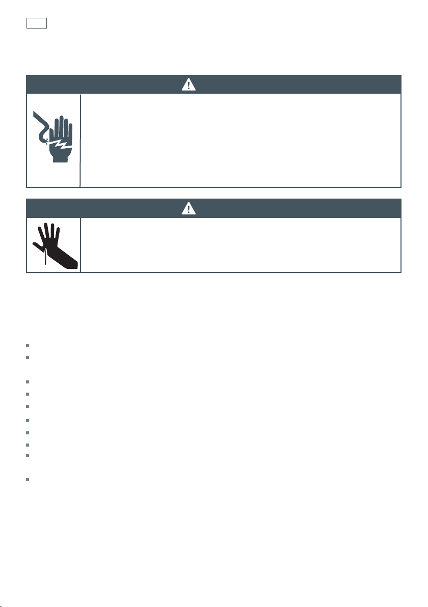
WARNING!
Electrical Shock Hazard
If the ceramic glass cooktop surface becomes cracked, switch the appliance
off at the mains power supply and call an Authorised Service Agent.
Always disconnect the cooker from the mains electricity supply before
carrying out any maintenance operations or repairs.
Failure to follow this advice may result in death or electrical shock.
Important safety instructions
General
To avoid hazard, follow these instructions carefully before installing or using this product.
Please make this information available to the person installing the product as it could reduce
your installation costs.
Installation must comply with your local building and electricity regulations.
Failure to install the cooker correctly could invalidate any warranty or liability claims.
Some appliances have a protective film. Remove this film before using the cooker.
Do not modify this appliance.
Do not operate your appliance by means of an external timer or separate remote-control system.
This appliance is to be installed and serviced only by an authorised person.
User servicing: do not repair or replace any part of the appliance unless specifically
recommended in the manual. All other servicing should be referred to a qualified technician.
Do not install or operate the appliance if it is damaged or not working properly. If you receive a
damaged product, contact your dealer or installer immediately.
Installation
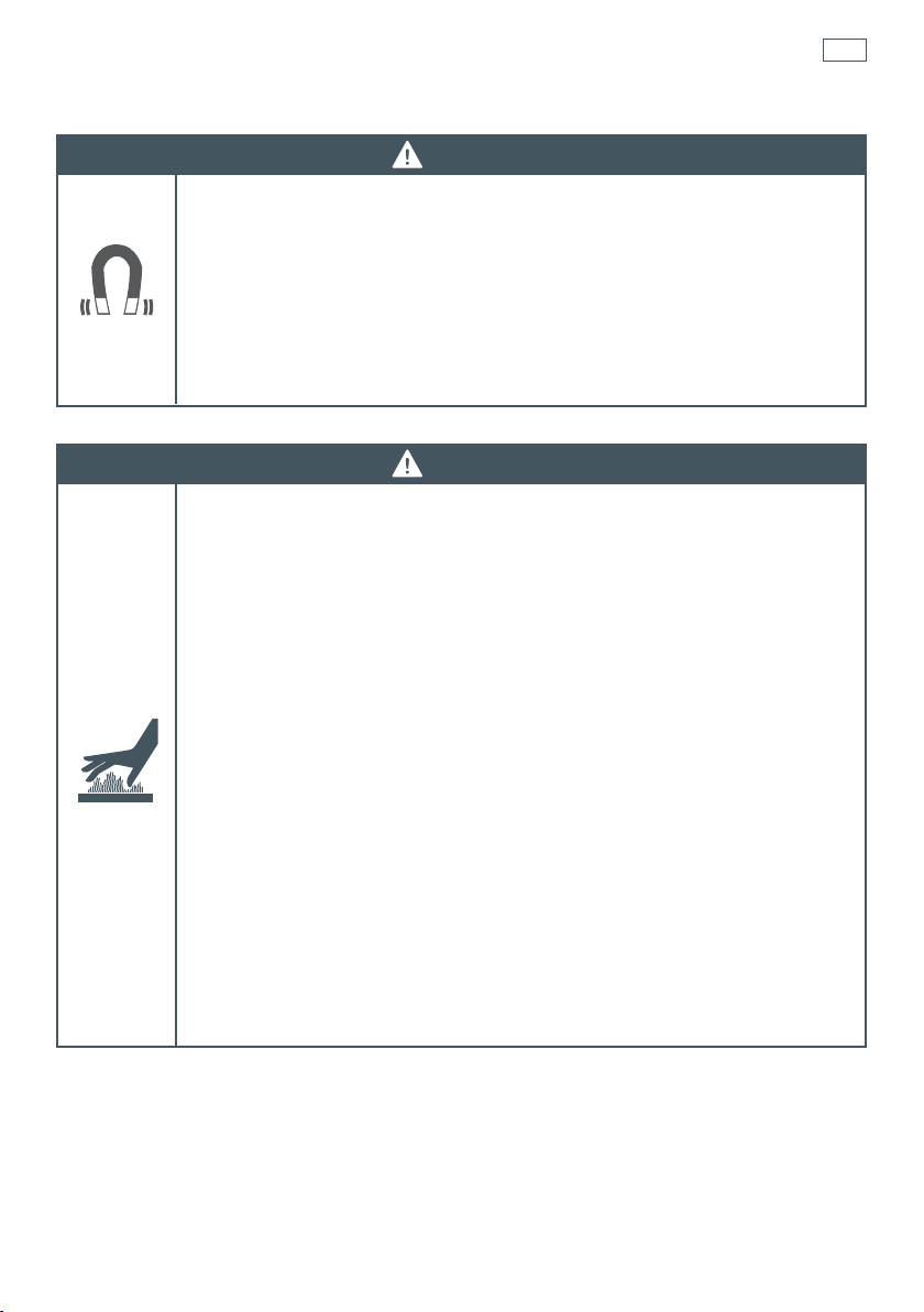
WARNING!
Cut Hazard
Take care - panel edges are sharp.
Failure to use caution could result in injury or cuts.

3
Electrical
This cooker is to be installed and connected to the electricity supply only by an authorised person.
If the installation requires alterations to the domestic electrical system, call a qualified
electrician. The electrician should also check that the electrical system is suitable for the
electricity drawn by the cooker.
The appliance must be connected to the mains electricity supply, checking that the voltage
corresponds to the value given in the rating plate and that the electrical cable sections can
withstand the load specified on the plate.
A suitable disconnection switch must be incorporated in the permanent wiring, mounted and
positioned to comply with the local wiring rules and regulations. The switch must be of an
approved type installed in the fixed wiring and provide a 3 mm air gap contact separation in all
poles in accordance with the local wiring rules.
In Australia and New Zealand, a switch of the approved type with a 3 mm air gap must be
installed in the active (phase) conductor of the fixed wiring.
The switch must always be accessible.
The power supply cable must not touch any hot parts and must be positioned so that it does not
exceed 75
O
C at any point.
To connect the cooker to the mains electricity supply, do not use adapters, reducers or branching
devices as they can cause overheating and burning.
This cooker must be connected to a suitable double pole control unit adjacent to the cooker. No
diversity can be applied to this control unit.
If the electrical supply cord is damaged, it must only be replaced by an authorised person.
In Australia and New Zealand: this cooker must be connected to electrical supply using V105
insulated cable.
In New Zealand, this appliance must be connected to the electrical supply using a cable fitted
with an appropriately rated plug. The plug must be compatible with the socket-outlet fitted to the
final subcircuit in the fixed wiring that is intended to supply the appliance.
In United Kingdom and Ireland: this cooker must be connected to electrical supply using H05RR-F
or H05VV-F insulated cable.
The cooker must be earthed.
Voltage and Power consumption
OR90SDBSIPX2 220-240/380-415 V 3N- 10850 W, 50 Hz 47.2A (230 V)*
* Diversity not applied.
Safety and warnings
4
Operation
Your freestanding cooker has been carefully designed to operate safely during normal cooking
procedures. Please keep the following guidelines in mind when you are using it:
Safety and warnings
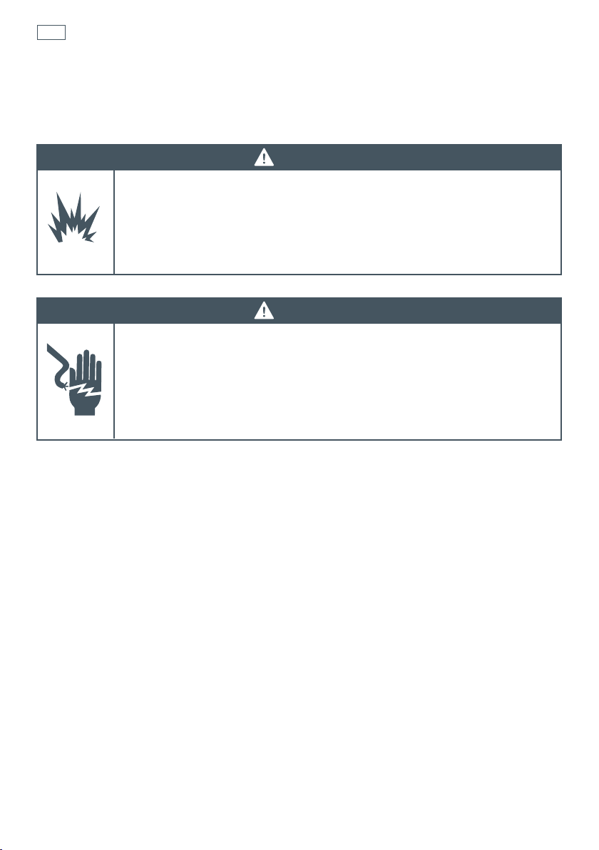
WARNING!
Electrical Shock Hazard
Switch the cooker off at the wall before replacing fuses or the oven lamp.
If the cooktop surface is cracked, switch the appliance off at the wall. Contact an
accredited
service provider to repair it, and do not use until it has been repaired.
Failure to do so may result in death or electrical shock.
WARNING!
Explosion Hazard
Do not store flammable materials such as gasoline near the cooktop.
Do not store flammable material in the oven or storage compartment.
Do not spray aerosols near the cooktop during use.
Failure to follow this advice may result in death or serious injury.
5
Safety and warnings
WARNING!
Health Hazard
This appliance complies with electromagnetic safety standards.
However, persons with cardiac pacemakers or other electrical implants (such as
insulin pumps) must consult with their doctor or implant manufacturer before
using this appliance to make sure that their implants will not be affected by the
electromagnetic field.
Failure to follow this advice may result in death.
WARNING!
Hot Surface Hazard
Accessible parts may become hot when this cooker is in use.
To avoid burns and scalds keep children away.
Do not let body, clothing or any item other than suitable cookware contact with
the ceramic glass until the surface is cool.
Never leave metal objects (such as kitchen utensils) or empty pans on the
cooktop as they can become hot very quickly.
Beware: magnetisable metal objects worn on the body may become hot in the
vicinity of the cooktop. Gold or silver jewellery will not be affected.
Keep children away.
Handles of saucepans may be hot to touch. Check saucepan handles do not
overhang other cooking zones that are on. Keep handles out of reach of children.
Do not touch hot surfaces inside the oven.
Use oven mitts or other protection when handling hot surfaces such as oven
shelves or dishes.
Take care when opening the oven door.
Let hot air or steam escape before removing or replacing food.
Do not touch the cooktop components, burners, trivets/pan supports or the base
when hot.
Before cleaning, turn the cooker off and make sure it is cool.
Failure to follow this advice could result in burns and scalds.

6
Safety and warnings
Important safety instructions
Never leave the appliance unattended when in use. Boilover causes smoking and greasy
spillovers may ignite.
NEVER try to extinguish a fire with water, but switch off the appliance and then cover flame eg
with a lid or a fire blanket.
WARNING: Danger of fire: do not store items on the cooking surfaces. Do not use your cooktop as
a work surface.
Do not use a steam cleaner on any part of your cooker.
Isolating switch: make sure this cooker is connected to a circuit which incorporates an isolating
switch providing full disconnection form the power supply.
Household appliances are not intended to be played with by children. Do not store things
children might want above the oven. Children could be burned or injured while climbing on the
oven to retrieve items.
Children of less than 8 years old must be kept away from the appliance unless continuously
supervised. This appliance can be used by children aged from 8 years and above, and persons
with reduced physical, sensory or mental capabilities or lack of experience and knowledge, if
they have been given supervision or instruction concerning the use of the appliance in a safe way
and they understand the hazards involved. Cleaning and user maintenance shall not be done by
children without supervision.
Safe food handling: leave food in the oven for as short a time as possible before and after
cooking. This is to avoid contamination by organisms which may cause food poisoning. Take
particular care during warmer weather.
If the electrical supply cord is damaged, it must only be replaced by an authorised person.
This cooker is not to be used as a space heater, especially if it is installed in marine craft or in a
caravan.
Operation
Do not place aluminium foil, dishes, trays, water or ice on the oven floor during cooking as this
will irreversibly damage the enamel.
Do not line the walls with aluminium foil. Do not stand on the door, or place heavy objects on it.
Do not place or leave any magnetisable objects (eg credit cards, memory cards) or electronic
devices (eg computers, MP3 players) near the appliance, as they may be affected by its
electromagnetic field.
We recommend using plastic or wooden kitchen utensils for cooking with your induction cooktop.
After use, always turn off the cooking zones. Do not rely on the pan detection feature to turn off
the cooking zones when you remove the pans.
Do not place or drop heavy objects on your cooktop.
Do not stand on your cooktop. Do not use pans with jagged edges or drag pans across the
ceramic glass surface as this can scratch the glass.

7
Safety and warnings
Important safety instructions
Do not use harsh abrasive cleaners or sharp metal scrapers to clean the ceramic glass cooktop
and the oven door glass since they scratch the surface, which may result in shattering of the
glass. Some heavy-duty and nylon scourers can scratch the ceramic glass cooktop. Always read
the label to check if your scourer is suitable for cleaning ceramic glass cooktops.
Do not use pans with rough circular base as these may scratch your cooktop.
Wear proper apparel. Do not wear loose fitting or hanging garments when using the appliance.
They could ignite or melt if they touch an element or hot surface and you could be burned.
Always keep oven vents unobstructed
Use only dry oven mitts or potholders. Moist or damp potholders on hot surfaces could result in
burns from steam. Do not let potholders touch hot areas or heating elements. Do not use a towel
or a bulky cloth for a potholder. It could catch fire.
Caution. Hot air can blow from the vent at the top of the oven as part of the oven’s cooling
system.
Placement of oven shelves: always position shelves in the desired location while the oven is cool
(before preheating). If a shelf must be removed while the oven is hot, do not let the oven mitts or
potholder contact hot heating elements in the oven or the base of the oven.
Follow the instructions on starting a Self Clean cycle (some models only). Items made from
combustible material (for example wood, fabric, plastic) may catch fire if left in the oven during a
Self Clean cycle.
Before starting a Self Clean cycle, remove oven shelves, side racks, and all other cookware/
utensils, and wipe up large food spills or grease deposits.
Before starting a Self Clean cycle, make sure you move any pet birds to another, closed and well-
ventilated room. Some pet birds are extremely sensitive to the fumes given off during a Self Clean
cycle, and may die if left in the same room as the oven during such a cycle. During a Self Clean
cycle, the oven reaches higher temperatures than it does for cooking. Under such conditions, the
surfaces may get hotter than usual and children should be kept away.
8
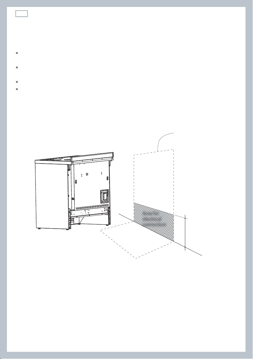
Dimensions and clearances
The cooker must be installed no less than 50 mm away from any side walls which exceed the
height of the cooktop.
The cabinetry surrounding the cooker must be made of heat-resistant material and must be able
to withstand temperatures of 65 °C above room temperature.
Do not install the cooker near flammable materials (eg curtains).
If you stand the cooker on a pedestal, make sure you provide safety measures to keep it in place.
Installation instructionsInstallation instructions
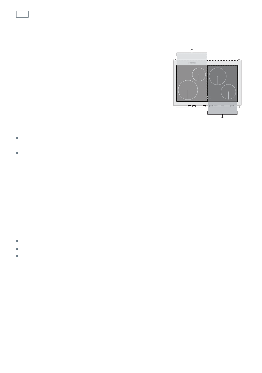
Locating the area for electrical connection
Fig. 1 Area for electrical connection
240 mm (*)
(*) Depending on
feet adjustment
Dotted line showing
the position of the
cooker when installed
Area for
electrical
connection
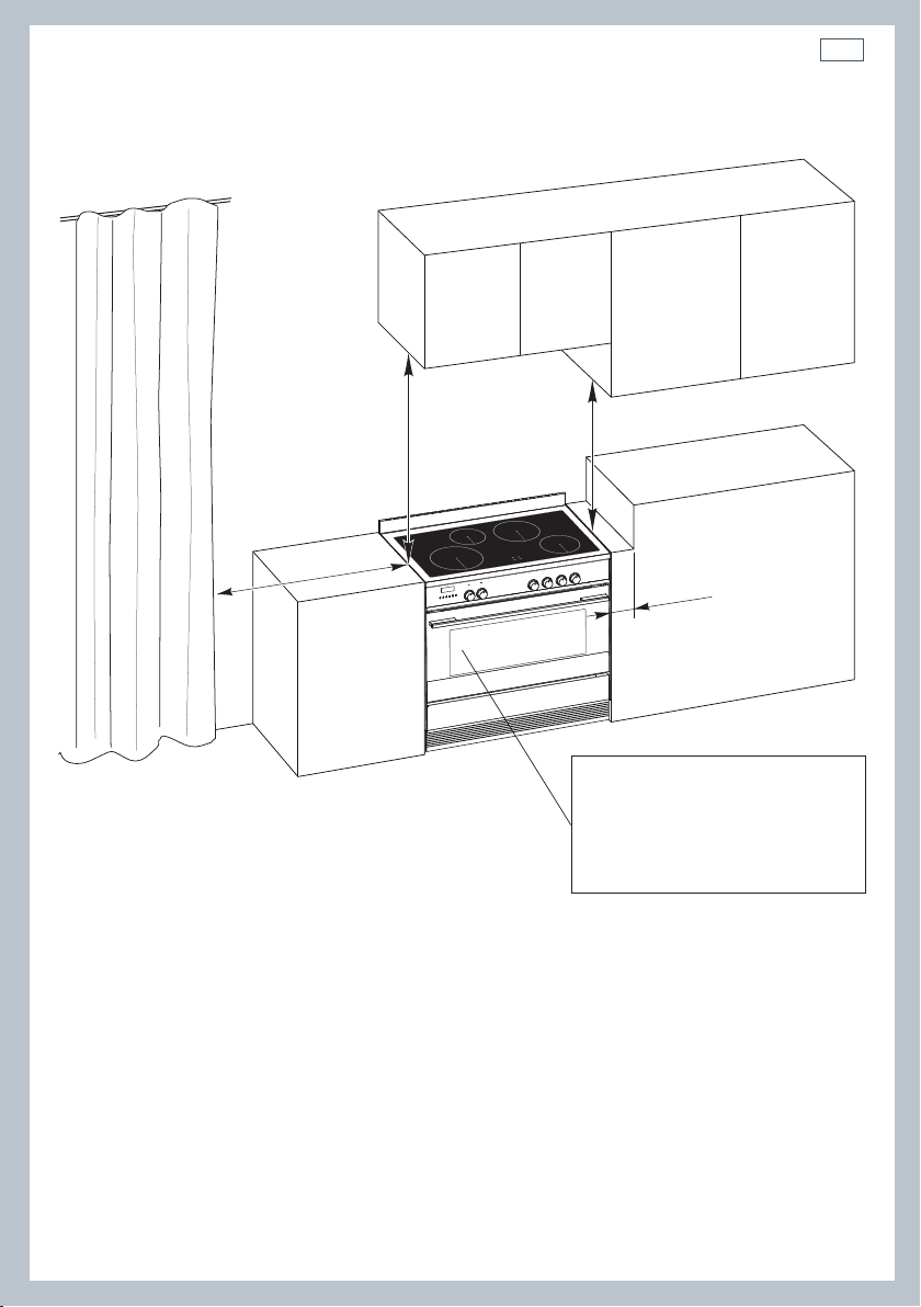
9
50 mm
650 mm
500 mm
450 mm
Cooker overall dimensions [mm]
•
height:
min 897 - max 910
•
product width: 897
•
depth: 600
•
cavity width 900
Fig. 2 Dimensions and
distances from cooker
Installation instructions
10
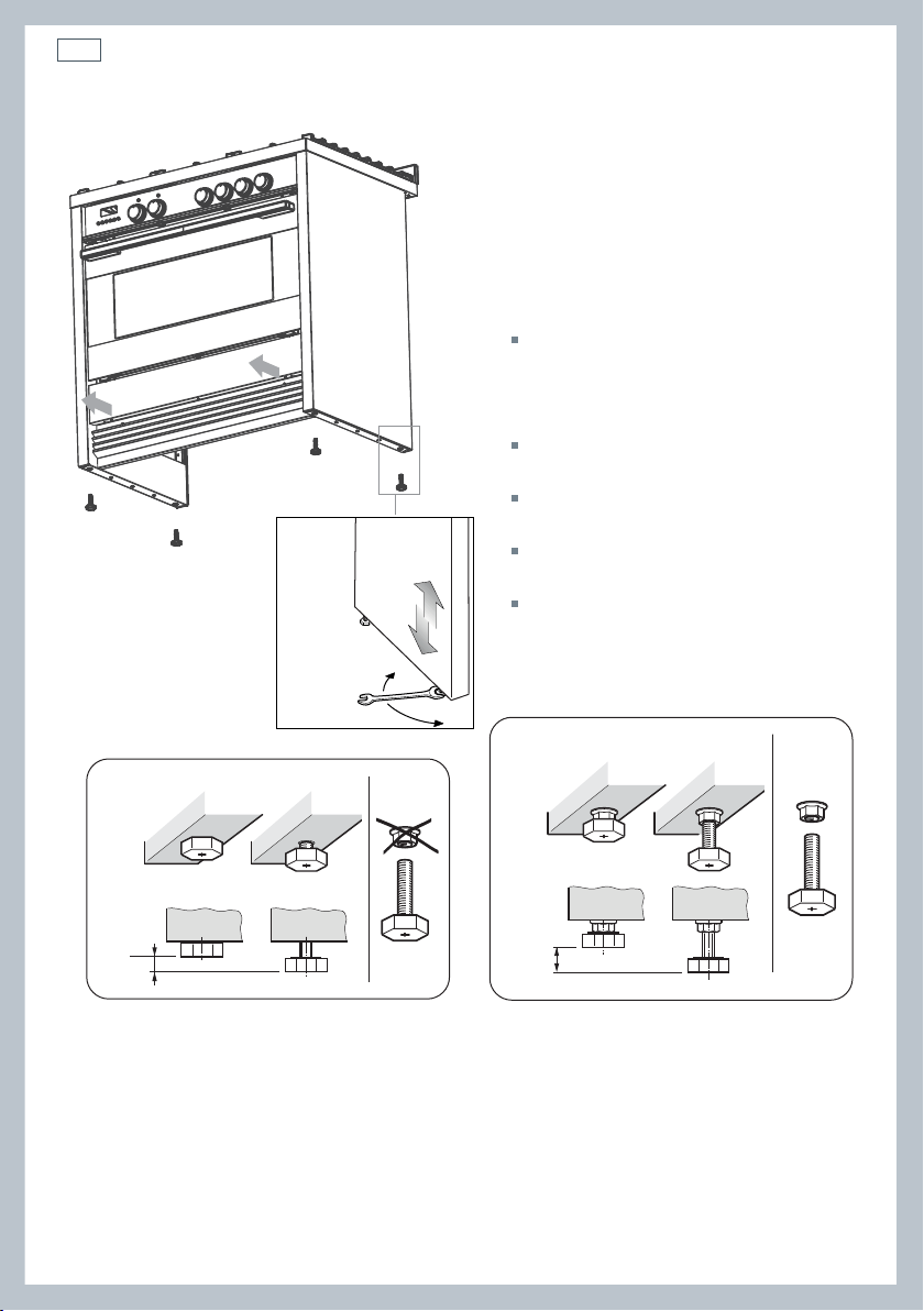
Installation instructionsInstallation instructions
+ 8
0
mm
+ 8
mm
+ 13
mm
Levelling the cooker
Important!
Using the supplied adjustable feet is
MANDATORY. For safety reasons and to
ensure adequate ventilation, the cooker
chassis MUST NOT sit directly on the floor, a
plinth, or other support surface.
For ease of installation, first remove
the kickstrip. To remove the kickstrip,
unscrew the two screws holding it in
place.
The cooker is already fitted with four
levelling feet.
Level the cooker by screwing or
unscrewing the feet.
Make sure you follow the instructions in
Figs. 3a, 3b, and 3c.
Note: nuts are supplied with the cooker
in a separate kit.
Do not refit the kickstrip until you have
installed the anti-tip bracket.
Fig. 3b Do not use the supplied nuts for height
adjustments between 0 and 8 mm
Fig. 3c Use the supplied nuts for
height adjustments between 8 and 13 mm
Fig. 3a Screw/unscrew the
feet to get the required height
11
Installation instructions
Dotted line showing the position
of the cooker when installed
Rear left
foot of cooker
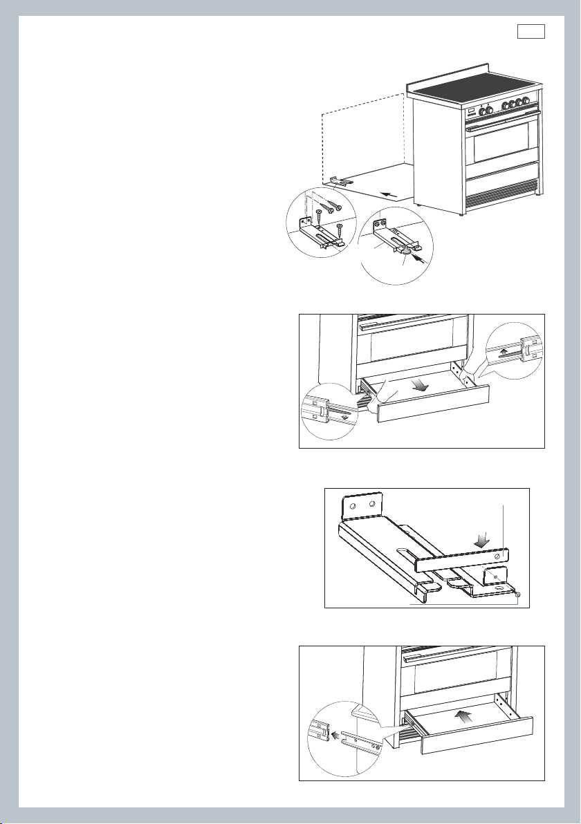
Anti-tilt
bracket
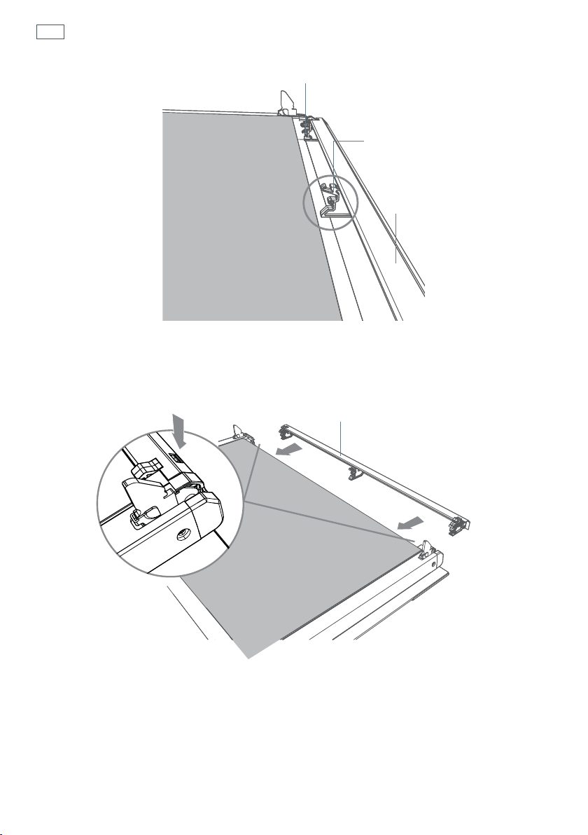
Fig. 4 Attaching the
anti-tilt bracket and
sliding the cooker
into place
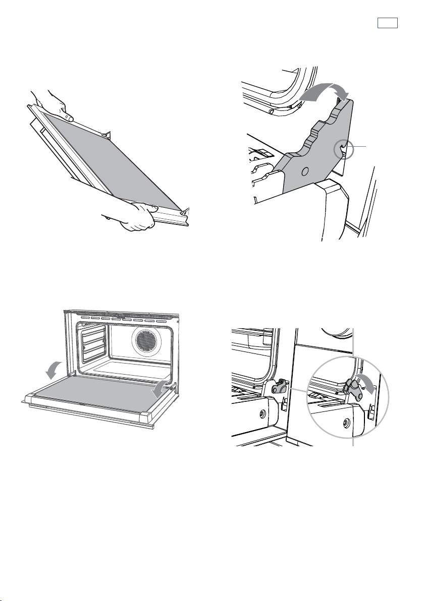
Fig. 5 Accessing the anti-tilt bracket
by removing the drawer
Fig. 7 Replacing the drawer
Fig. 6 Fixing the restraining plate
Restraining plate
Screw & Washer
Fitting the anti-tilt bracket
Important!
To restrain the appliance and prevent
it tipping accidentally, the anti-
tilt bracket and restraining plate
supplied must be fitted according to
the instructions below.
1
Drill four 8mm diameter holes for
the fixing screws (two in the wall
and two in the floor-see Fig.4) and
insert the plastic plugs supplied.
Important!
Before drilling the holes, check that you will not
damage any pipes or electrical wires.
2
Attach the anti-tilt bracket to the floor and
rear wall using the four screws supplied, as
shown in Fig. 4.
3
After attaching the anti-tilt bracket securely,
slide the cooker into place. Ensure that the
left rear foot slides under the bracket, as
shown in Fig.4.
4
Access the bracket by removing the drawer
(Fig. 5):
a
Slide out the drawer completely.
b
Press the lever of the left guide rail
down and pull the lever of the right
guide rail up.
c
Holding the levers, disengage and
remove the drawer.
5
If fitted, remove the kickstrip (see ‘Levelling
the cooker’). Fix the restraining plate by
sliding it into place and securing it with the
fixing screw and washer supplied. See Fig. 6.
6
Replace the drawer (Fig. 7):
a
Insert the drawer rails into the guide
rails.
b
Gently push the drawer in
completely; the safety catches will
automatically hook.
7
Replace the kickstrip using the two screws.
Important!
Beware of sharp edges when removing or
replacing the drawer.
12
Installation instructionsInstallation instructions
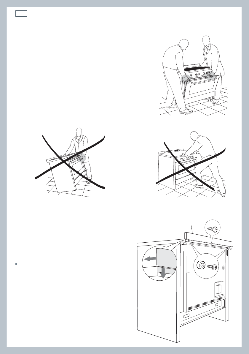
Important!
To prevent damaging the adjustable feet or lower
trim, ensure the cooker is always lifted by two
people.
Do not lift the cooker by the door handles.
DO NOT DRAG the cooker. Lift the feet clear of the
floor.
Take extra care not to damage the door sensor (top
left of oven).
Moving the cooker
Fig. 8 Correctly lifting the cooker
Fig. 10 Incorrectly moving the cookerFig. 9 Incorrectly lifting the cooker
Fixing the backguard
Before installing the cooker, assemble the
backguard “C” .
The backguard “C” can be found packed
at the rear of the cooker.
1
Before assembling, remove any protective
film/adhesive tape.
2
Remove the two spacers “A” and the
screw “B” from the rear of the cooktop.
3
Assemble the backguard as shown and
fix it by screwing the central screw “B”
and the spacers “A”.
Fig. 11 Assembling
the backguard
A
B
C
13
Installation instructions
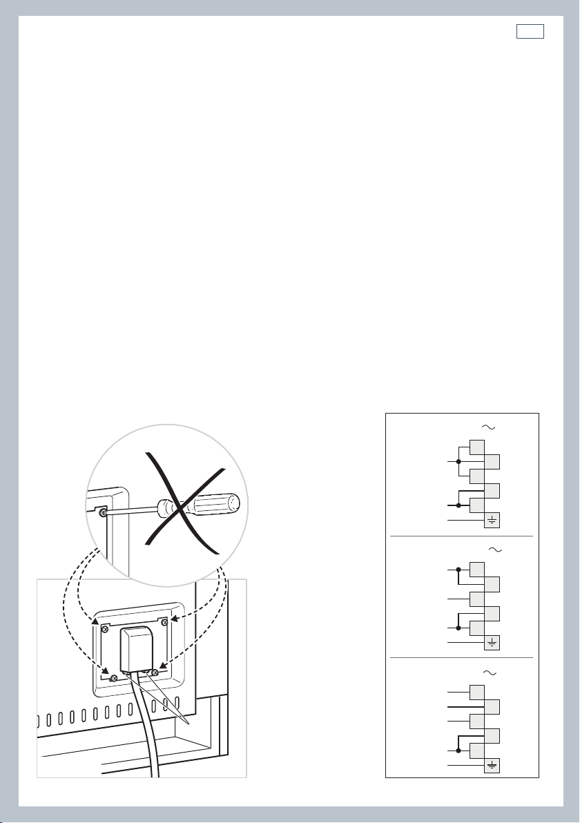
Connecting the power supply cable
Important!
This cooker must be connected to the electricity supply only by an authorised person.
To connect the power supply cable to the cooker, it is necessary to:
1 Unhook the terminal board cover by inserting a screwdriver into the two hooks ‘A’ (fig. 12).
2 Unscrew the screw ‘D’ and open completely the cable clamp ‘E’ (figs. 14).
3 Position the U bolts ‘F’ onto terminal board ‘G’ (figs. 14) according to the diagrams in fig. 13.
4 Connect the phase, neutral and earth wires to terminal board ‘G’ according to the diagrams in
figs. 13 - 14.
5 Strain the feeder cable and block it with cable clamp ‘E’ (by screwing screw ‘D’).
6 Close the terminal block cover (check the two hooks ‘A’ are correctly hooked).
Important!
To connect the power supply cable DO NOT unscrew the screws fixing the cover plate behind the terminal
block.
WARNING: If the power supply cable is damaged, it must be replaced only by an authorised service agent in
order to avoid a hazard.
Voltage and power consumption
220-240/380-415 V 3N~ 50 Hz 47.2A (230V) 10850 W (diversity not applied)
A
PE
N (L2)
L
1
220-240 V
1
2
3
4
5
1
2
3
4
5
PE
380-415 V 2N
N
L1
L2
1
2
3
4
5
PE
380-415 V 3N
N
L1
L3
L2
Fig. 12 Terminal block Fig. 13 Connection diagrams
14
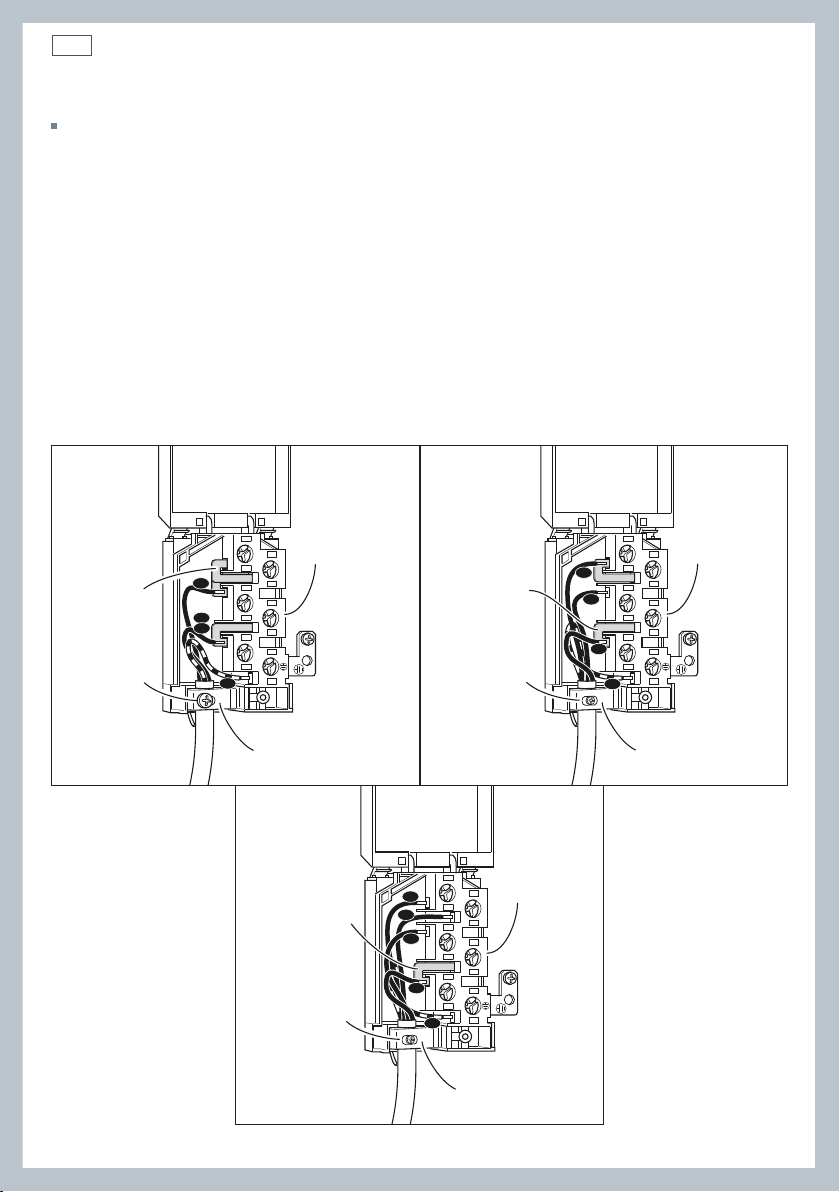
Installation instructions
Feeder cable section
In Australia and New Zealand: this cooker must be connected to electrical supply using V105
insulated cable.
220-240 V~ 3 x 6 mm
2
(*)
380-415 V 3N~ 5 x 2,5 mm
2
(*)
380-415 V 2N~ 4 x 6 mm
2
(*)
* Connection with wall box connection.
- Diversity factor applied.
- A diversity factor may be applied to the total loading of the appliance only by a suitably
qualified person.
~
1
2
3
5
4
N
L2
PE
L1
G
F
D
E
220-240 V
1
2
3
5
4
PE
N
L1
L2
G
F
D
E
~
380-415 V 2N
1
2
3
5
4
PE
N
L1
L2
L3
G
F
D
E
~
380-415 V 3N
Fig. 14 Connection diagrams
15
Installation instructions
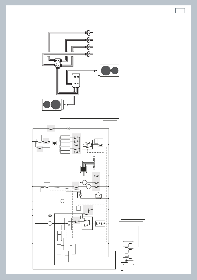
Wiring diagram
ELECTRIC DIAGRAM KEY
F1 Oven switch
ST Safety thermostat
STL Safety thermal overload
TL Thermal overload
TL1 Induction hob thermal overload
PR Electronic programmer
PB Temperature probe
TS Oven temperature selector
EC Oven function selector (encoder)
SF State functions
DL Door lock device
DS Door sensor
R1 Relay 1
R2 Relay 2
R3 Relay 3
LF Oven lamp
TR Oven lamps transformer
S1 Door lock indicator lamp
S2 Line pilot lamp
C Oven top heating element
G Oven grill heating element
SI Oven bottom heating element (int.)
SE Oven bottom heating element (ext.)
CI Oven circular heating element
IU-LH Induction unit, left zones
IU-RH Induction unit, right zones
UD Induction units user display
PCB Induction units PCB
RSI Rotary selector interface
DLM Door lock motor
GIR Rotisserie motor
V Oven fan motor
CF Cooling fan motor
RS Resistance (220 Ohm)
R Product relay
M Terminal block
T Earth connection
R1
R
R
R2
R3
X1
PR
TL1
F1
F1
F1
F1
F1
F1
F1
EC
P4
PB
PHV
SF
TS
X0
LF
TR
LF
V
GIR
CF
P7
P6
P11
11
11a
12
12a
13
13a
14
14a
15
15a
P8
P9
PT1
PT2
5a
5
16
16a
6a
6
2
2a
1
1a
A
B
1
2
46
79
7a
7
8a
8
4
4a
3
3a
1
1
2
2
4
9
9a
F1
S2
S1
DLM
RS
TL
STL
ST
PR
DL
DS
PR
PR
G
SI
SE
CI
C
IU-LH
IU-RH
RSI RSI RSI RSI
UD
PCB
42
135
M
T
N
L1
N
L1
X6/X18/X19
X6/X18/X19
X1
X2
X8


17
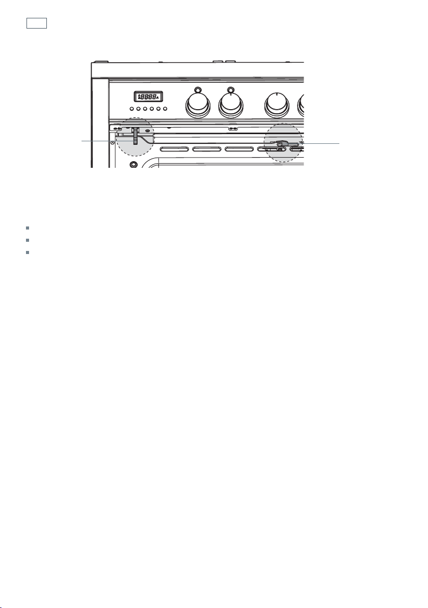
Fig. 15 Control panel
1
Control buttons
2
Clock display
3
Temperature dial
4
Function dial
5
Front left cooking zone dial
6
Rear left cooking zone dial
7
Rear right cooking zone dial
8
Front right cooking zone dial
9
Function indicator light
10
Door lock indicator light
2910
134 5678
First use
18
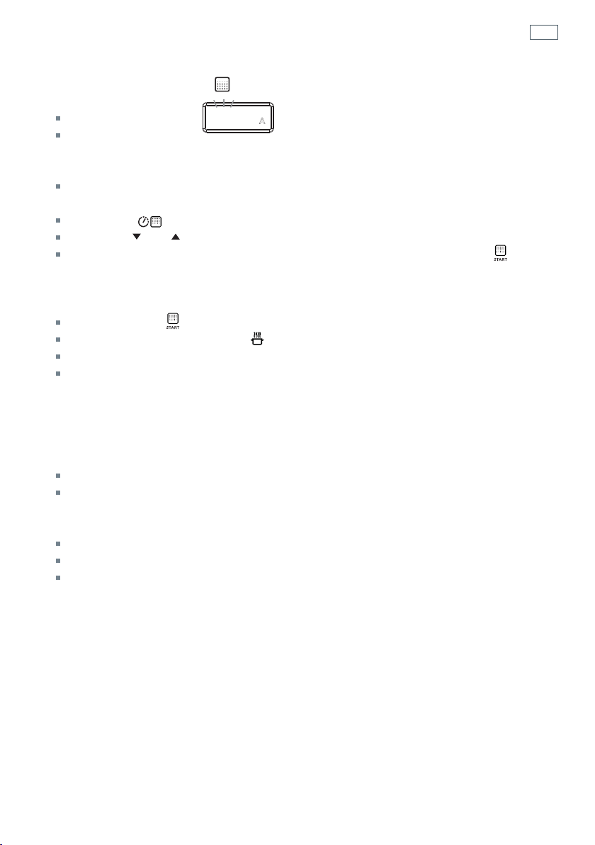
First use
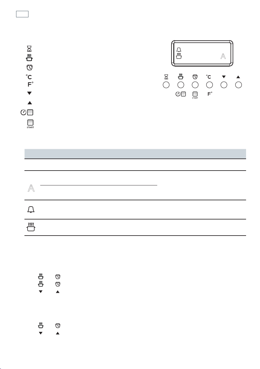
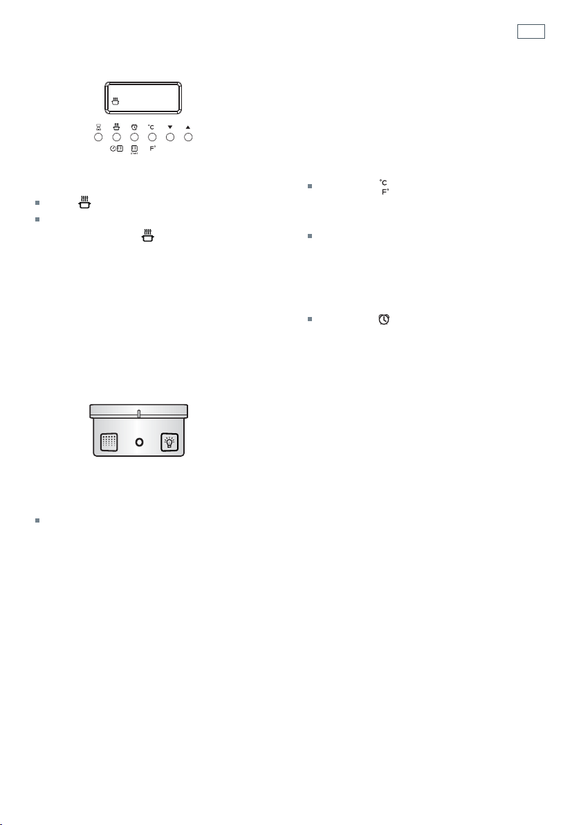
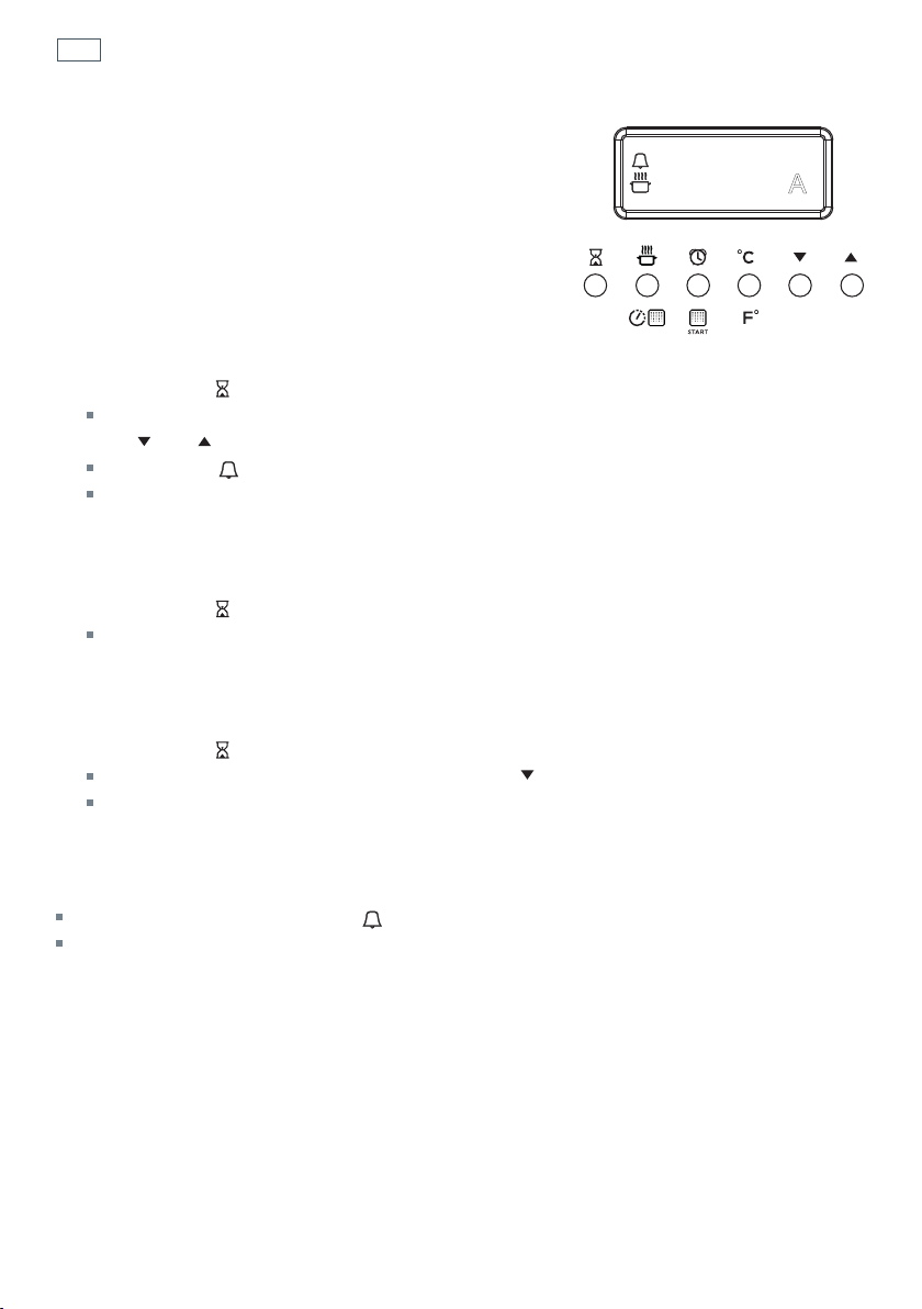
Fig. 16 Clock display and control buttons
Buttons
sets the timer
sets the cooking time
sets the stop time for automatic cooking
set the oven temperature /
select Celsius or Fahrenheit
decreases the time and temperature
increases the time and temperature
sets the Self Clean time
starts the Self Clean cycle
Illuminated symbols
If the display shows It means that... For more information
flashing
12:00
The clock needs to be set. See instructions below.
steadily lit
The oven is set for automatic
cooking.
See section ‘Automatic cooking’
flashing and
beeping
Automatic cooking has finished
steadily lit The timer is set See section ‘Using the electronic timer’
steadily lit The oven is heating up See section ‘Using your oven’
To set the clock
When the power to the appliance is turned on or restored after a power failure 12:00 will flash in
the display.
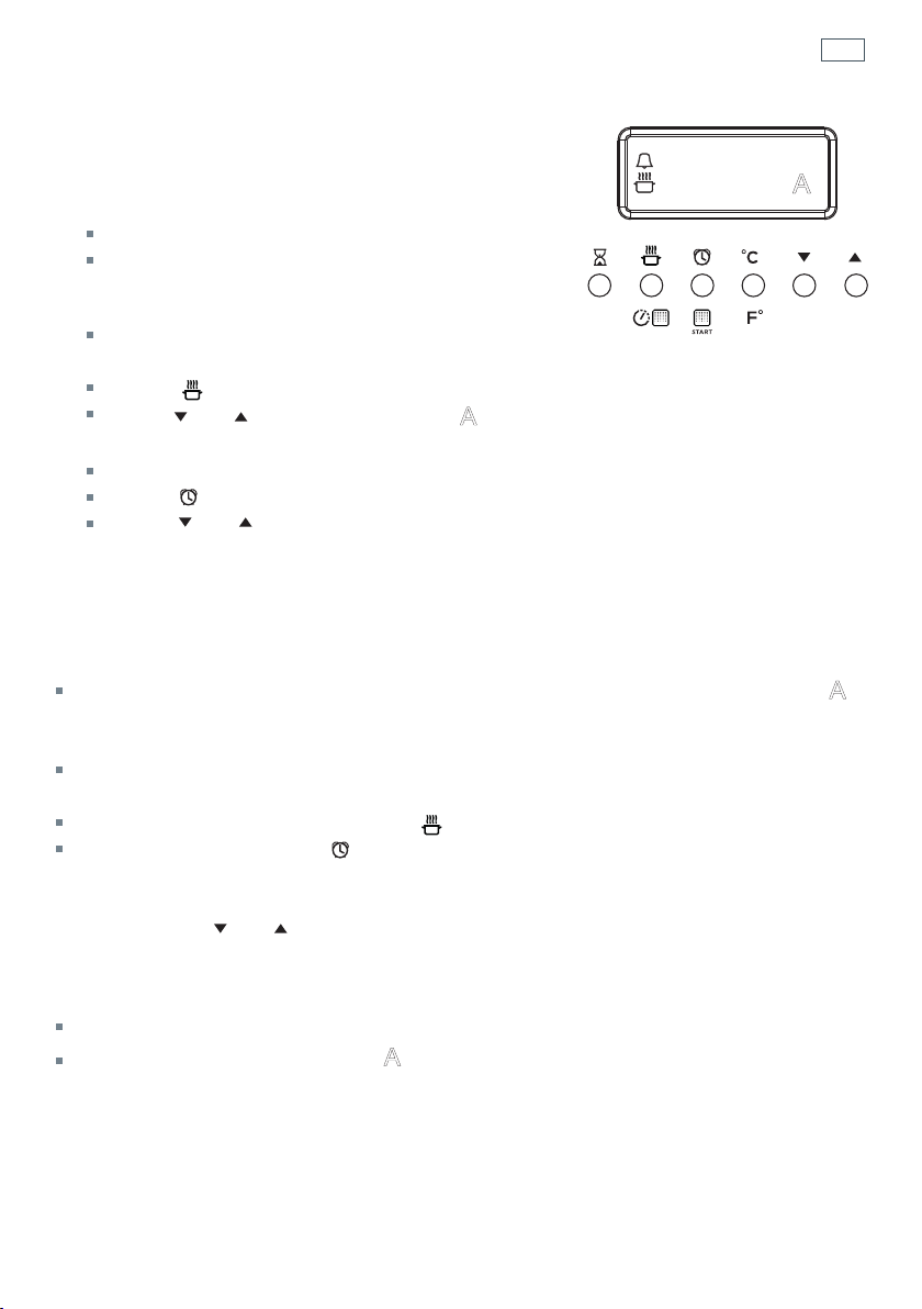
1 Press
and together - the display will stop flashing. The clock is now set for 12:00.
2 Press
and together again to change the time. The display will flash
3 Press
and to set the time. After a few minutes the display will be steadily lit, showing the
time is set.
To change the time
1 Press and together. The display will flash.
2 Press
and to set the time.
After a few seconds the display will remain steadily lit, showing the time is set.
12:00
A
0
A
19
Using your oven
Before using your new oven, please:
1
Read this user guide, taking special note of the ‘Safety and warnings’ section.
2
Remove all accessories and packaging. Peel the protective film off all surfaces and accessories.
3
Set the clock. The oven will not work until the clock has been set. See ‘Setting the clock’.
5
If not already fitted, fit the telescopic sliding shelf supports.
See ‘Care and cleaning’ for instructions.
6
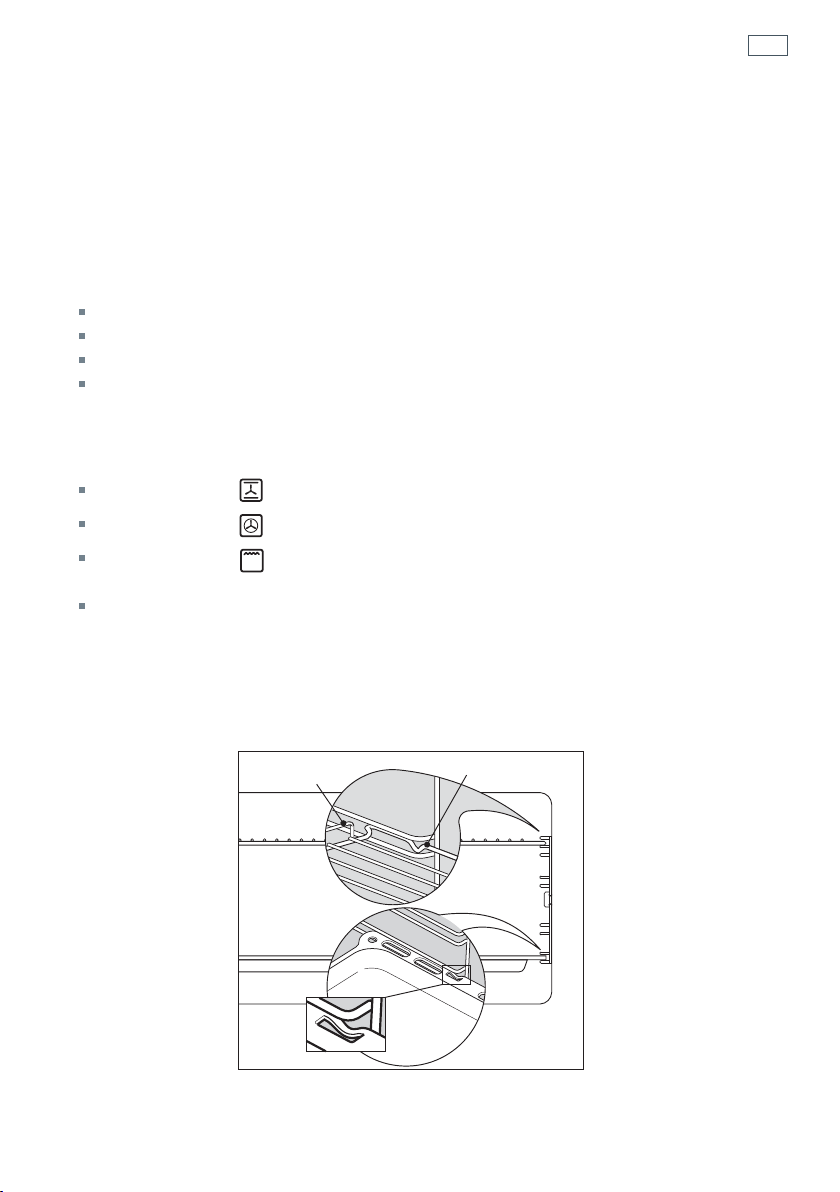
Slide in the shelves you will need, making sure that:
they are between the two wires of a shelf position;
the stop notches point down;
the guard rail is at the back.
Note: the grill tray should be positioned between the two wires of a shelf position and
orientated as shown.
7
Heat the oven on maximum for:
60 minutes in the position
30 minutes in the position
15 minutes in the position
There will be a distinctive smell while you are conditioning your oven. This is normal, but
make sure your kitchen is well ventilated during the conditioning.
8
Once cooled, wipe out the oven with a damp cloth and mild detergent, and dry thoroughly.
Fig. 17 Correct position of shelves
and grill tray
Guard rail
Stop notch
Stop
notch
20
Using your oven
210 C 225C
Fig. 18 Function and temperature dials
FUNCTION TEMPERATURE
1
Select a function
Rotate the function dial to select a function
The function indicator light will come on.
The preset function temperature will flash
in the display. (Each cooking function has a
preset temperature)
If you wish to use the oven at the preset
temperature -
After a few seconds, the display will stop
flashing and the oven will turn on and
heat up. The display will revert to show the
actual oven temperature.
The indicator will show in the display.
Note: if you select , the display will
show dEF. The temperature cannot be
adjusted when using this function.
2a
Adjust the temperature
There are two ways to set the
temperature while the display is
flashing:
Rotate the temperature dial (clockwise
to increase and anticlockwise to
decrease the temperature);
OR
Use the and buttons to increase
or decrease the set temperature.
After a few seconds, the display will stop
flashing and the oven will turn on and
heat up. The display will revert to show
the actual oven temperature.
The indicator will show in the
display.
Note: if the temperature display stops
flashing before you have set the
required temperature, you can:
2b
Press the button
The display will flash
2c
Use the and buttons to increase
or decrease the set temperature.
Door lock
indicator light
Function
indicator light
21
Using your oven
C89
FUNCTION
3
When the oven is preheating and during
cooking
the indicator will show in the display.
When the oven has reached the set
temperature the
indicator will go out.
Note: this indicator may turn on and off
during cooking as the oven maintains the
set temperature.
5
When you have finished cooking
Turn the function dial to O (off) to turn the
oven off.
4a
To check the set temperature
Press the button.
The display will flash showing the set
temperature.
After a few seconds the display will return
to the actual oven temperature and the
display will be steadily lit.
4b
To check the time of day
Press the button.
After a few seconds the display will show
the oven temperature again.

22
Cooking functions
OVEN LAMP
Only the oven light comes on. It remains on in all the cooking functions.
DEFROST
this is not a cooking function
Only the oven fan comes on. The fan circulates air around the oven, speeding up the defrosting
process by approximately 30%. Note: this function is not for cooking food.
FAN FORCED
The circular heating element and the fan come on. The oven set on FAN FORCED can cook
several different foods together. Use FAN FORCED for multi-shelf cooking.
BAKE
The upper and lower heating elements come on. BAKE is the traditional method of cooking. It
is best to cook on only one shelf at a time in this function. Ideal for large cakes and dishes that
bake for several hours.
FAN BAKE
The upper and lower heating elements and the fan come on. Ideal for dishes like lasagne that
need to brown on top and also single trays of small cakes or biscuits that bake in less than an
hour.
GRILL
Grill is the most suitable function for ‘finishing off’ many meals, for example browning the top
of potato gratin and frittata. Use Grill to toast bread or to grill your favourite chicken, fish and
steak. Use with the oven door closed and the temperature set to a maximum of 225°C. For best
results, use the topmost shelf position when you want quick browning (eg toast).

23
Cooking functions
ROTISSERIE
A delicious way to cook meat and poultry. The slowly rotating meat is basted continuously
in its own juices, making it tender on the inside and well browned and full of flavour on the
outside. See ‘Using the rotisserie’.
SELF CLEAN
this is not a cooking function
The oven heats to a high temperature, reducing food residue to a fine ash that can be wiped out
with a damp cloth.
Important!
Safe food handling: leave food in the oven for as short a time as possible before and after cooking or
defrosting. This is to avoid contamination by organisms which may cause food poisoning. Take particular
care during warmer weather.

24
Cooking guide
Changing the oven from Celsius to Fahrenheit
You can set your oven to display the temperature in Fahrenheit or Celsius.
1
Select a cooking function.
2
While the display is flashing, press to reduce the oven to the minimum temperature
(50
o
C / 120
o
F).
3
When the display stops flashing , press and hold the button until C or F flashes in the display
4
Press the button to change between Celsius (C ) and Fahrenheit (F).
After a few moments the oven will turn off and the display will show the time of day.
Turn the function dial back to O (off).
Cooking Guide
The settings in the following chart are guidelines only. Follow the instructions in your recipe or
on packaging and be prepared to adjust the oven settings and baking times to achieve the best
possible results for you.
Shelf positions are counted from the oven floor up (1 is the lowest, 5 is the highest).
Arrange oven shelves before you turn the oven on, then preheat the oven to the desired
temperature.
Single shelf positions below use the flat oven shelf; where a multi-shelf arrangement is
recommended, the lower position uses the step-down shelf.
Due to the width of the oven, a single shelf can usually accommodate double the standard
recipe.
Always preheat the oven before baking.
Do not place anything, including water or ice, on the oven floor.
Keep the door completely shut when grilling foods.
Do not open the door during the first 3/4 of baking time.
25
Cooking guide
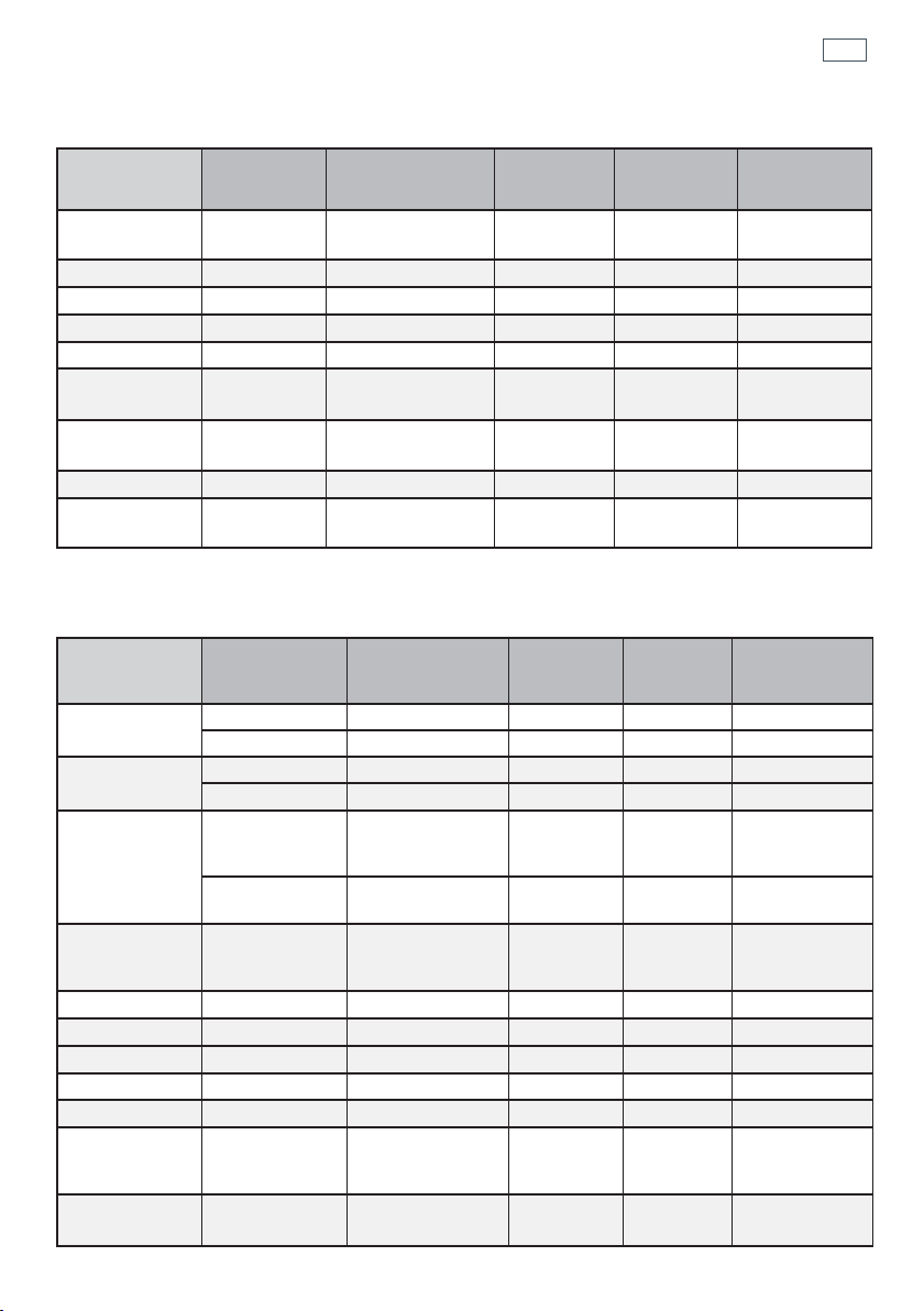
SAVOURY
BAKING
Food Shelves
Recommended
Function
Shelf
positions
Temp (°C) Time (mins)
Roast Chicken
Rotisserie Rotisserie 1 180-210
15-20
min/450g
Lasagne
Single Fan Bake 3 175-180 45-50
Quiche
Single Bake 1 180-200 30-40
Pizza
Single Bake 3 225-250 10-15
Casserole
Single Fan Forced 3 170-190 55-70
Roast Lamb
(bone in)
Single
Fan Forced
(medium)
3 160-170
18-28
min/450 g
Baked
Potatoes
Single Bake 4 175-190 40-50
Beef Steak
Single Grill 4 Hi 6-8 min / side
Beef Burgers
Single Grill 4 Hi
12-15
min / side
Food Shelves
Recommended
Function
Shelf
positions
Temp
(°C)
Time (mins)
Small cakes
single shelf Bake 2 180-190 20-30
multi shelf Fan Forced 1 and 3 160-170 30-40
Scones
single shelf Bake 2 210-230 15-20
multi shelf Fan Forced 1 and 3 210-230 15-20
Sponge
two small pans
(20 cm), on
single shelf
Bake 2 170-180 30-45
one large pan
(26 cm)
Bake 2 175 30-40
Light fruit
cake
two pans (21
cm) on single
shelf
Bake 2 155-165 90
Rich fruit cake
Single Bake 2 130-150 3-6 hrs
Apple pie
Single Bake 1 185 35-45
Quiche
Single Bake 1 180-200 30-40
Meringues
Single Bake 1 100-120 60
Bread rolls
Single Bake 1 210-230 15-20
Mu ns
2 x 12 muffin
trays on single
shelf
Fan Forced or
Fan Bake
3 190-200 10-15
Pastry case
(baked ‘blind’)
one 21 cm flan
tin
Bake 1 200
10 with beans,
then 10 without
26
Using the rotisserie
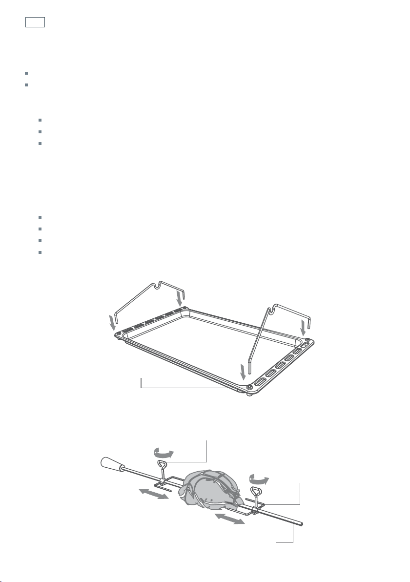
Fig. 19b Secure the meat
Fig. 19a Prepare the rotisserie supports
Important!
If fitted, remove the sliding shelf supports from shelf position 1 before using the rotisserie.
Remove all oven shelves and trays.
1
Prepare the rotisserie supports.
Place the grill tray on the benchtop.
Insert the supports into the lock studs.
Push the supports all the way down to lock them in firmly.
2
Secure the meat.
Important!
Take care, the forks are sharp!
When securing the meat, ensure that:
the skewer goes through the centre of the meat
the forks hold the meat firmly in place
the fork screws are tightened
there are no loose or projecting parts. Poultry should be trussed.
Note: the rotisserie can rotate up to 6 kg of meat and is long enough to cook two chickens at the
same time.
Lock stud
Fork
Skewer
Rotate the fork screws to loosen and tighten
27
Using the rotisserie
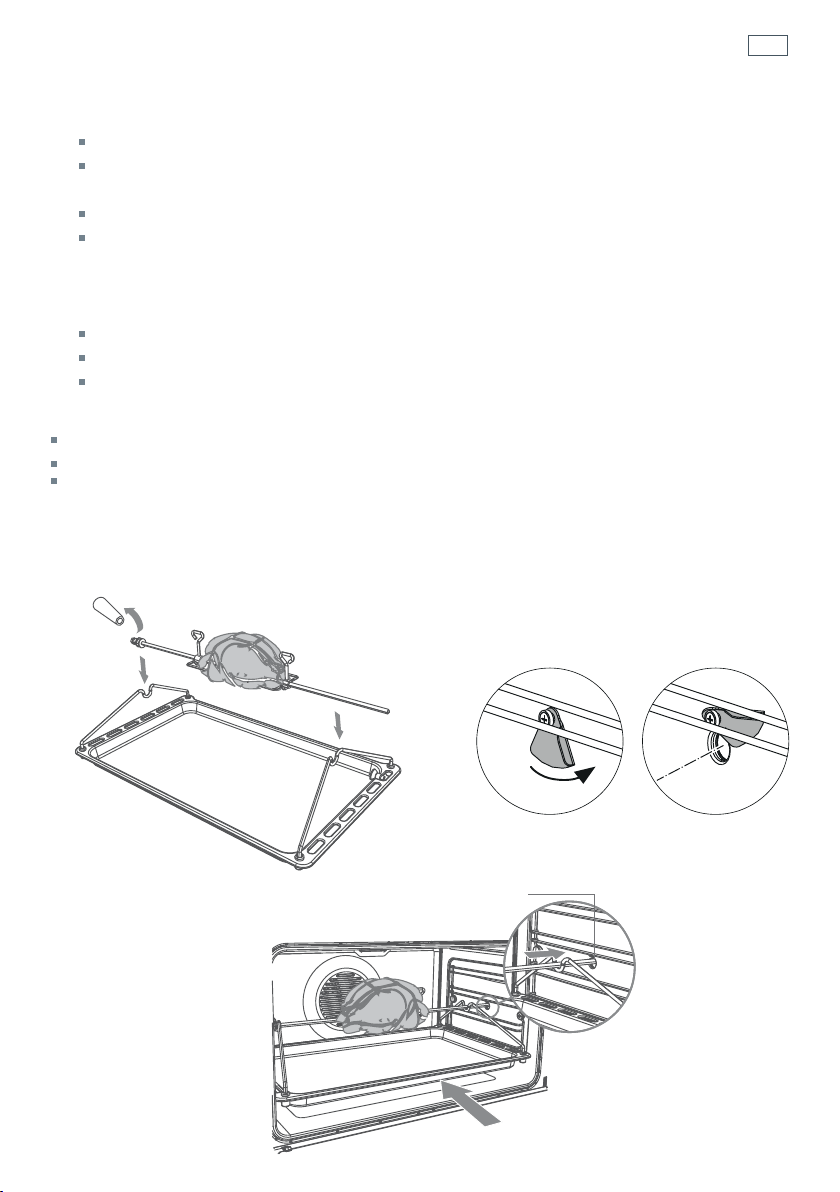
Fig. 19e Place the rotisserie in the oven
Fig. 19c Position the
skewer on the supports
Fig. 19d Rotisserie drive hole cover
3
Position the skewer on the supports.
Place the skewer on the supports, and check that the meat does not touch the grill tray.
Twist the handle off. It must not be left in the oven.
4
Place the rotisserie in the oven.
Slide the grill tray all the way to the back on shelf position 1.
Move the rotisserie drive hole cover aside (right-hand wall of the oven). Insert the skewer
fully into the rotisserie drive hole. Ensure the left hand side of the skewer is properly
located on the supports.
5
Start the rotisserie
Select the Rotisserie function.
Set the temperature.
The rotisserie will start to rotate.
Important!
Always turn the function dial to O (off) before removing the rotisserie.
Always ensure that poultry is cooked thoroughly.
During use, the rotisserie components become hot. If you leave the oven door open after using
the rotisserie, parts of the control panel may also become hot. Use oven mitts and take extra care,
especially when removing the rotisserie support rack from the hot oven.
Rotisserie drive hole
28
Using the electronic timer
You can use the timer at any time, even when
the oven is not in use.
Important!
The timer does NOT turn the oven off.
To set the timer
1
Press the timer button.
The time will show
0:00
2
Press and buttons to set the time you want (up to 3 hours in one minute steps)
The timer
indicator will come on.
After a few seconds the time will start counting down, the display will show the time of
day (if the oven is off) or temperature (if the oven is on) and will be steadily lit.
To check the remaining time
3
Press the timer button.
The timer counts down in minutes (hr:min) until the last minute when it counts down in
seconds.
To cancel the timer
4
Press the timer button.
The remaining time will be displayed. Press the
button to scroll the time down to 0:00
After a few seconds the clock will show the time of day (if the oven is off) or temperature
(if the oven is on).
When the time is up
The timer will beep and the timer
indicator go out.
Press any button to stop the beeping.
12:00
A
29
Automatic cooking
To set the oven for automatic cooking
1
Set the oven
Check the clock shows the correct time (eg 12:07).
Select the function and set the temperature.
The oven will turn on.
2
Set the cooking time
Decide how long the food will take to cook, allowing
time for preheating if necessary (eg 40 minutes).
Press
.
Use
and
to set the cooking time.
0
A
will show in the display.
3
Set the stop time
Decide when you want your food to be ready by (eg 13:30).
Press
.
Use
and to set the stop time.
You can turn the oven on manually and set it to turn off automatically by setting the stop time
(step 3 above).
When automatic cooking is set
If there is time before cooking starts, the oven will turn off and the pre-set temperature and
0
A
will show in the clock display, indicating the oven is set for automatic cooking. Note: the cooling
fan may stay on.
The oven will automatically turn on at the required time (eg 12:50) and turn off at the set stop
time (eg 13:30).
To see the remaining cooking time, press
.
To see the set stop time, press
.
To cancel automatic cooking
1
Press and hold and together for 3 seconds.
2
Turn the function dial to O (Off).
When the stop time is reached
The oven will turn off, the timer will beep.
The display will show End and the
0
A
will flash.
1
Press any button to stop the beeping.
2
Turn the function dial to O (Off).
12:00
A
30
Induction cooktop introduction
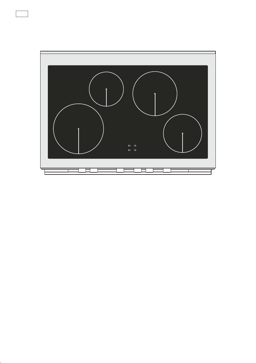
1
2300 W (3000 W *) zone
2
1400 W zone
3
Cooking zones display
* Maximum power output when set for PowerBoost (see section ‘Using your cooktop’s special
features’)
Important!
Disconnect the appliance from the mains if the ceramic glass is cracked and contact Customer Care.
Metallic objects such as knives, forks, spoons and lids should not be placed on the cooktop surface since
they can get hot.
Fig 20 Cooktop layout
1
1
2
3
2
31
Induction cooktop introduction
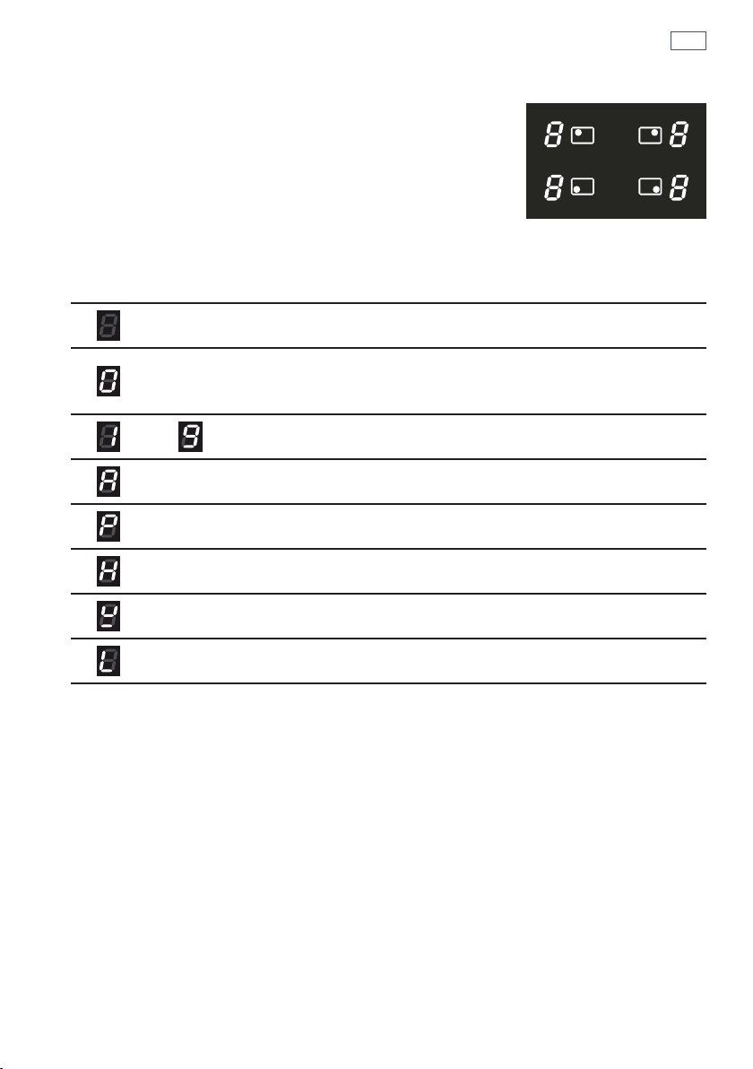
Cooking zones display
The ceramic cooktop is fitted with induction cooking zones.
These circular zones are controlled by separate dials positioned
on the control panel below.
At the front, is the display for the cooking zones (one for each zone).
Each zone display is activated by it’s corresonding control dial and
displays:
= Cooking zone Off (not activated)
= Cooking zone On (activated but not operating).
If all the zones are in zero setting, the display switches off automatically
(cooking zones Off ) after about 10 seconds.
-
= Power levels
= Auto Heat-reduce feature
= PowerBoost feature
= Hot Surface indicator
= Pan detection indicator
= Childlock
Note: each lit figure refers to the relevant cooking zone
Fig 21 Cooking zones diplay
32
Choosing the right cookware
1
1
3
2
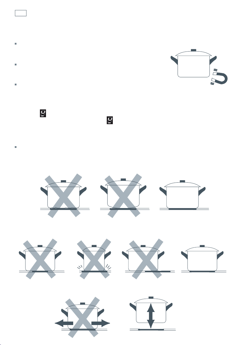
Important!
Only use cookware with a base suitable for induction cooking.
Look for the induction symbol on the packaging or the bottom of
the pan.
You can check whether your cookware is suitable by carrying out
a magnet test. Move a magnet towards the base of the pan. If it is
attracted, the pan is suitable for induction.
If you do not have a magnet:
1
Put some water in the pan you want to check.
2
Place a suitable pan on the cooking zone you wish to use. Make sure the bottom of the pan
and the surface of the cooking zone are clean and dry. Turn on the cooking zone.
3
If does not flash in the display and the water is heating, the pan is suitable.
Note: If the pan detection symbol
does appear on the display, your pan is not suitable
and the cooktop will not operate. After 10 minutes without detecting any pan, the cooking
zone switches off automatically and can only be switched on after the control dial has
been returned to “0” (Off).
Cookware made from the following materials is not suitable: pure stainless steel, aluminium or
copper without a magnetic base, glass, wood, porcelain, ceramic, earthenware.
Do not use cookware with jagged edges or a curved base.
Make sure that the base of your pan is smooth, sits flat against the glass, and is approximately
the same size as the cooking zone. Always centre your pan on the cooking zone.
Always lift pans off the cooktop– do not slide, or they may scratch the glass.
33
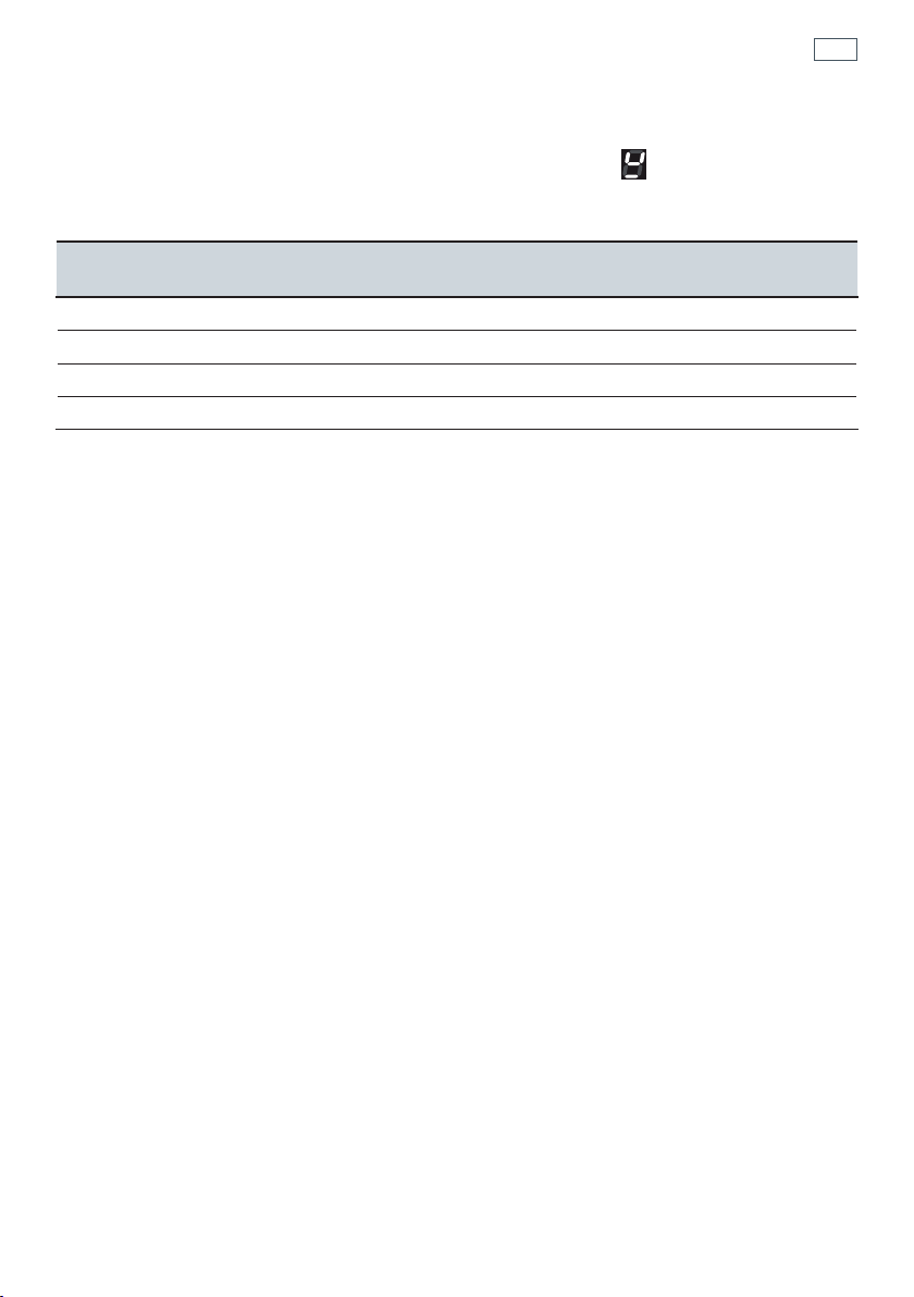
Choosing the right cookware
Important!
the cooking zones will not operate if the pan diameter is too small ( will appear on the
cooking zone display). To correctly use the cooking zones follow the indications given in the
following table.
Note: some types of pans can cause noise when used on an induction cooking zone.
This noise does not mean any failure on the appliance and does not influence the cooking
operation.
Induction cooking zone
Minimum pan diameter
recommended
Maximum pan diameter
recommended
Front right 110 mm 240 mm
Rear right 145 mm 300 mm
Rear left 110 mm 240 mm
Front left 145 mm 300 mm
34
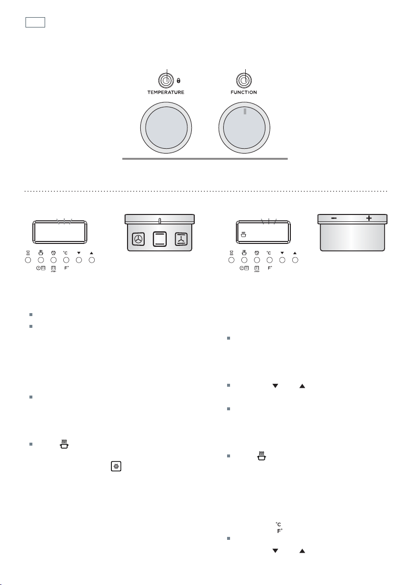
Using your induction cooktop
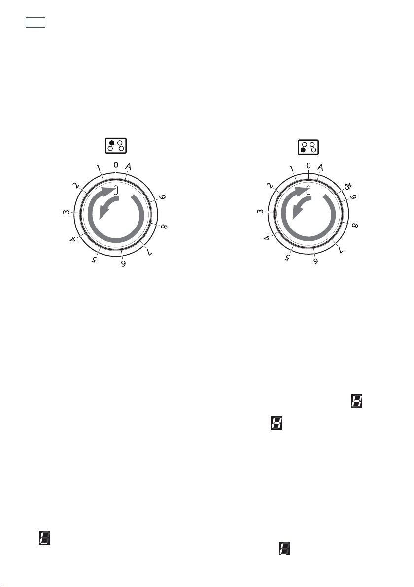
Control dials
Each cooking zone is activated by a separate control dial positioned on the control panel. The
functions are arranged on the actual dial itself.
If a cooking zone is not turned off (‘0’ position) the electronic system automatically switches it off
after a pre-set time ranging from 90 minutes to 6 hours, depending on the power setting.
Power level
Turn the dial clockwise to set the desired power level between 1 (minimum) and 9 (maximum).
The power level can be modified at any time by turning the dial clockwise or anti-clockwise to a
different setting.
The cooking zone display shows the selected level.
Hot Surface Indicator
When the temperature of a cooking zone is still hot, the relevant Hot Surface indicator lights
up on the display to alert you of the hot surface. Avoid touching the cooktop surface over the
cooking area. Please pay special attention to children. When the
is lit on the display, it is
still possible to start cooking again; just turn the control dial to the required power level. The
indicator will disappear when the surface has cooled down to a safe temperature.
Childlock
When not using the induction cooktop, set the Childlock to prevent children from accidentally
switching on the cooking zones.
Ensure all cooking zones are switched Off (‘0’ position), then turn the control dials of the left
cooking zones simultaneously to the left (‘A’ setting) and hold the dials in this position until
lights up on the cooking zones display; then release the dials.
To deactivate the childlock repeat the same procedure until the
goes out; then release
the dials.
1
2
1
2
Fig 22 Control dial -
rear left & front right zone
Fig 23 Control dial -
front left & rear right zone
35
Using your cooktop’s special features
Using the Auto Heat-reduce feature
This feature is available on all the cooking zones
Turn the control dial anti-clockwise to the ‘A’ setting and then release the dial (after the ‘beep’);
the
symbol lights up on the corresponding cooking zone display. Within 5 seconds turn the
dial to the desired power level (between 1 and 9); once a setting has been selected,
and the
chosen power level will flash in alternation on the control panel display.
This feature allows the cooking zone to operate at the maximum power (100%) for a time
proportional to the selected power level; after this time the cooking zone will operate at the
selected level.
While this feature is operating it is possible, at any time, to increase the selected power level but
it is not possible to decrease the power.
The Auto Heat-reduce feature can be disabled by turning the dial anti-clockwise to a lower
power level, turning the dial to the ‘0’ (Off) position or by selecting the PowerBoost feature.
Note: If removing the pan from the cooking zone before the programme has been completed,
the Auto Heat-reduce feature will be completed with the remaining time if the pan is put back
on the cooking zone within 10 minutes.
Using the PowerBoost feature
This feature is available on the front left/rear right zones only.
Turn the control dial clockwise to set the maximum power level (9), then turn clockwise again to
the
setting and release the dial (after the ‘beep’); the control dial returns to the maximum
setting (9) automatically and the
symbol lights up on the corresponding cooking zone
display. The PowerBoost feature is now on.
This feature allows the cooking zone to operate at the PowerBoost maximum power (above the
rated power) for a maximum of 5 minutes; it could be used, for example, to rapidly heat up a
large amount of water. After 5 minutes
will flash for a few seconds. The cooking zone will
then decrease to power level 9.
The PowerBoost feature can be disabled by turning the dial anti-clockwise to a lower power
level, turning the dial to the ‘0’ (Off ) position or by turning the dial again to the
setting; in
this case the cooking zone operates at the power level 9.
Note: if a cooking zone is still hot, it is not possible to use the PowerBoost feature and
will
flash if you try to activate. The cooking zone is automatically set to the maximum power level (9).
The PowerBoost feature is always limited to a maximum of 5 minutes. You can activate the
PowerBoost feature again after 5 minutes.
Important!
The PowerBoost feature is not suitable for use with non water based cooking.
Do not use this function for heating oil (e.g. deep fat frying). The power density may be too high
and it could damage the cookware.
36
Using your cooktop’s special features
Maximum usable power for the cooking zones
The right and left cooking zones are controlled by two
separate power boards and the maximum total power per
each power board is 3700 W.
Should the cooking zones of one power board require more
than 3700 W, the last selected power level has priority and the
power of the other cooking zone is automatically reduced to
the remaining power available.
If this occurs, the cooking zone will display a flashing figure
for about 3 seconds before automatically displaying the new
power level.
This means for example that:
When setting PowerBoost for the second zone, the setting for the other zone could be reduced
to the remaining power available.
When setting PowerBoost for a zone and then another setting on the second zone, if the total
power exceed 3700 W the PowerBoost feature is automatically turned off and the power reduced
to the maximum power available.
Thermal protection
The induction cooktop is fitted with safety devices to protect the electronic system and to
protect each cooking zone from overheating.
In case of overheating, one of the following automatic functions could be started by the
electronic system:
PowerBoost feature automatically turned off and power reduced;
one or more cooking zone switched off;
cooling fan motor of the induction unit switched on.
Controlled by
1st power board
Controlled by
2nd power board
37
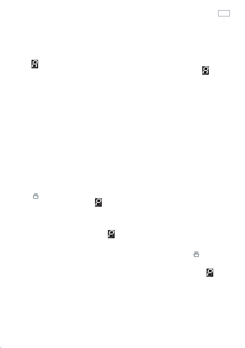
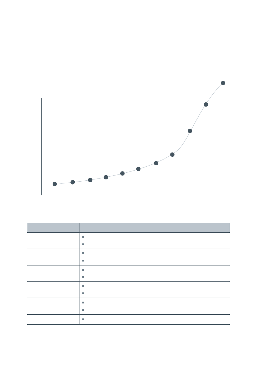
Heat settings
The settings below are guidelines only. The exact setting will depend on several factors,
including your cookware and the amount you are cooking. Experiment with the cooktop to find
the settings that best suit you. In general, the lower heat settings offer a more gradual control,
whereas the higher heat settings have a more pronounced step change in power.
Percentage of power %
100
80
60
40
20
0
u123456789P
Heat setting
(A)
Heat setting
Suitability
1
-
2
delicate warming for small amounts of food
melting chocolate, butter, and foods that burn quickly
3
-
4
gentle simmering
cooking rice
5
-
6
rapid simmering
pancakes
7
-
8
sautéing
cooking pasta
9
stir-frying
searing
P
boiling water
Cooking guidelines
Note: the settings and suitability shown are subject to variability due do differences in cookware construction.

38
Important!
Before you start cleaning your cooker, please:
Read these cleaning instructions and the ‘Safety and warnings’ section at the start of this user
guide.
Turn the cooker off at the wall.
Make sure the cooker is a safe temperature to touch.
Do not use a steam cleaner.
Do not keep flammable substances in the oven.
General advice
Wipe down the cooktop and wipe out the oven after every use.
Wipe up spills. Avoid leaving alkaline or acidic substances (such as lemon juice or vinegar) on
the surfaces.
Do not use cleaning products with a chlorine or acidic base (ie citrus-based cleaners).
Cleaning the outside of the cooker
Important!
Do not use abrasive cleaners, cloths or pads on the outside surfaces.
Immediately wipe off any caustic cleaners if they are spilled onto the oven door handle.
Wipe the outside surfaces often, using warm water and a mild household detergent. The
stainless steel may also be cleaned with a suitable cleaner and polish.
Note: if you choose to use a commercial stainless steel cleaner, please read the label to make
sure it does not contain chlorine compounds as these are corrosive and may damage the
appearance of your cooker.
Care and cleaning

39
Care and cleaning
Caring for your cooktop
Important!
Some heavy-duty and nylon scourers can scratch the ceramic glass of your cooktop. Always read
the label to check if your scourer is suitable for cleaning ceramic glass cooktops.
Use ceramic glass cleaner on the cooktop while it is warm to touch. Rinse and wipe dry with a
clean cloth or paper towel. The cooktop may become stained if cleaning residue remains.
Remove any food, spillovers or grease from the cooktop while it is still warm using a razor blade
scraper suitable for ceramic glass surfaces. Do not use knives or any other sharp object for
cleaning. Take extra care to avoid damaging the seal at the edges of the ceramic glass surface.
Do not use cleaning products with a chlorine or acidic base.
Metallic stains
Copper-based or aluminium cookware may cause metallic staining. These stains show as a
metallic sheen on the cooktop. If the cooktop is not cleaned after every use and the stains
are allowed to burn onto the surface, they may react with the glass and will no longer be
removable. To help prevent such damage, clean the cooktop after every use and apply a
glass cooktop conditioner.
Cleaning melts and spillovers
Anything that melts onto the ceramic glass surface or food spills with a high sugar content may
cause pitting of the ceramic glass surface if they are left there to cool. Examples include:
plastic wrap
melted aluminum foil
sugar, sugary syrups, jams and jellies
vegetables and vegetable water with a high sugar content eg peas, sweet corn, beetroot.
Remove these spills immediately with a special razor blade cooktop scraper, taking care not to
scratch the glass. Follow the steps below:
1 Turn the element off and carefully scrape the spill to a cool area of the cooktop surface.
2 Clean the spill up with a cloth or paper towel.
3 As soon as the cooktop is cool enough to safely touch, clean with cooktop cleaner.
Cleaning the stainless steel surround strip
To remove fingerprints and other marks, wipe with a clean damp cloth and dry with a lintfree
cloth.
40
Care and cleaning
Cleaning the inside of your oven
Note: if using the Self Clean function remove all shelves and side racks first. See ‘Using the Self
Clean function’.
Do not use abrasive cleaners, cloths or pads to clean the enamel.
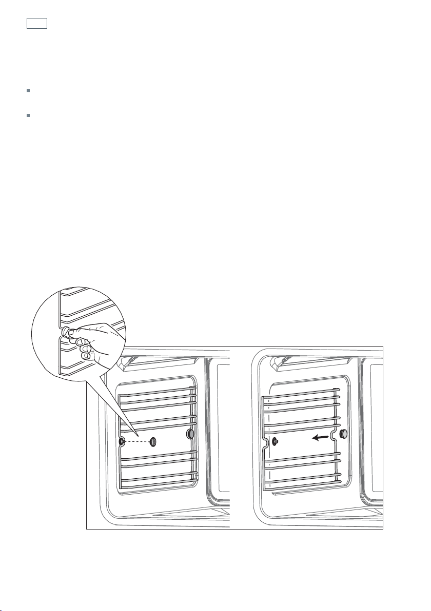
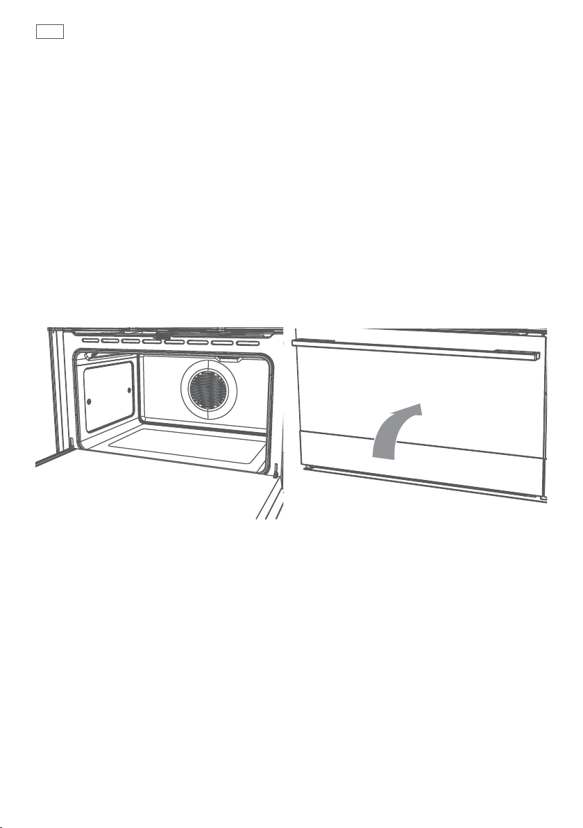
Removing the side racks
1
Using a small coin or a flat-head screwdriver, loosen and remove the front fixing screw only.
2
Slide the side rack clear of the rear lock stud and remove.
Refitting the side racks
3
Slide the side rack gently so it engages with the rear lock stud. Make sure that they are the right
way up, as in the illustrations, and then insert and tighten the front fixing screw.
4
If not already fitted, fit the telescopic sliding shelf supports. See “Care and cleaning’ for
instructions.
Fig. 24 Removing the side racks
41
Care and cleaning
Cleaning the enamel cavity
Clean the enamel on the inside of the oven when it has cooled down, using household
detergents. You may use ‘off the shelf’ oven cleaners, if you carefully follow the manufacturers’
instructions.
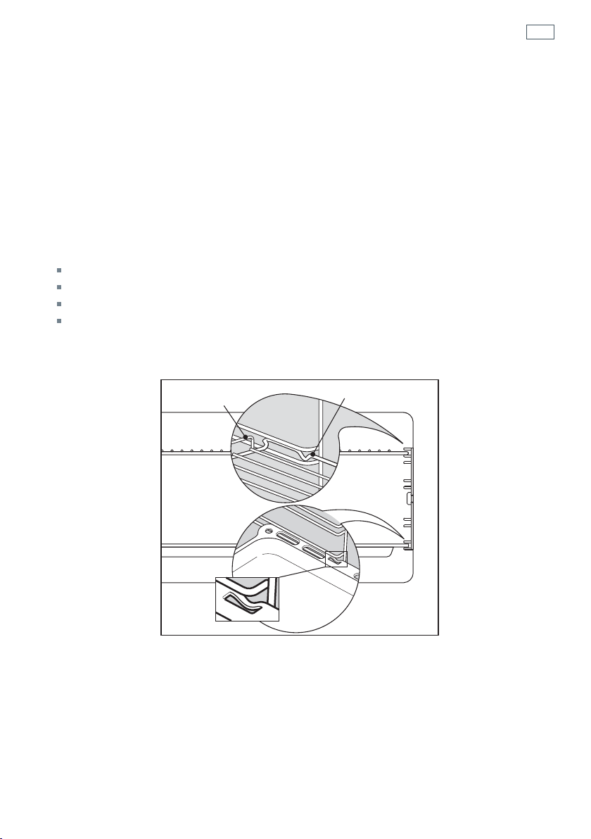
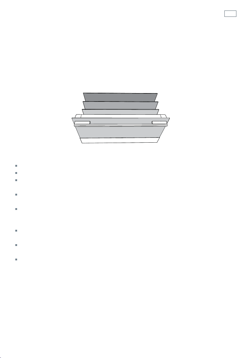
Cleaning the grill tray and shelves
Clean these in hot, soapy water.
After cleaning slide in the shelves, making sure that:
they are between the two wires of a shelf position;
the stop notches point down;
the guard rail is at the back.
Note: the grill tray should be positioned between the two wires of a shelf position and
orientated as shown.
Guard rail
Stop notch
Stop
notch
Fig. 25 Oven shelves and grill tray
42
Care and cleaning
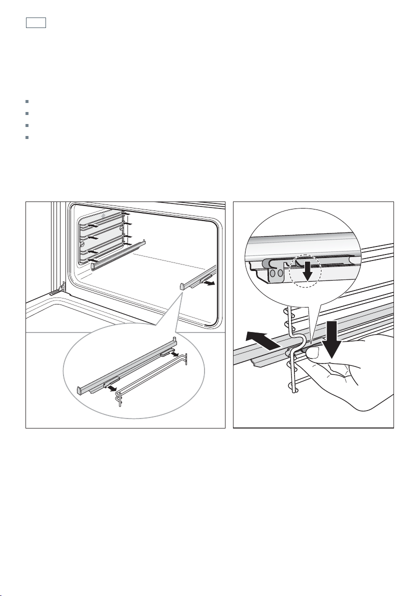
Fitting and removing the sliding shelf supports
When fitting the sliding shelf supports, make sure that you fit:
the side racks
the slides to the top wire of a shelf position
both sides of each pair of slides
both slides on the same level.
Important!
Remove the side racks first to make removing the sliding shelf supports easier.
Fig. 26b Removing the sliding shelf supports
Fig. 26a Fitting the sliding shelf supports
1
2
1
43
Care and cleaning
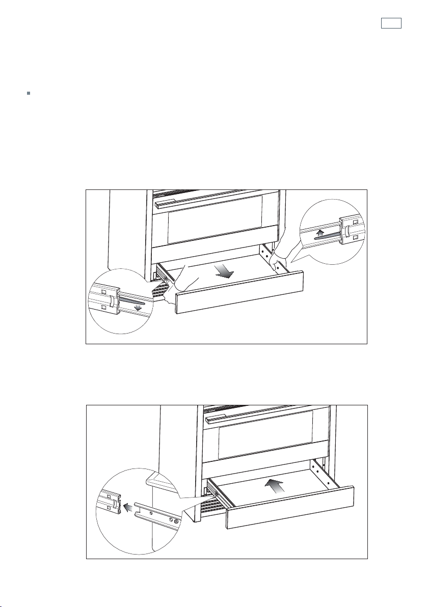
Storage Drawer
The drawer opens like a normal drawer. The draw slides stop the drawer from sliding all the way
out.
To remove the drawer
1
Open the drawer fully
2
Press the lever on the left guide rail down and the right guide rail up.
3
Holding the levers, disengage and remove the drawer. Do not use excessive force or you may
damage the drawer slides.
Replace the drawer
1
Insert the drawer rails into the guide rails.
2
Gently push the drawer in completely, the catches will automatically hook.
Fig. 27 Removing the drawer
Fig. 28 Replacing the drawer
44
Care and cleaning
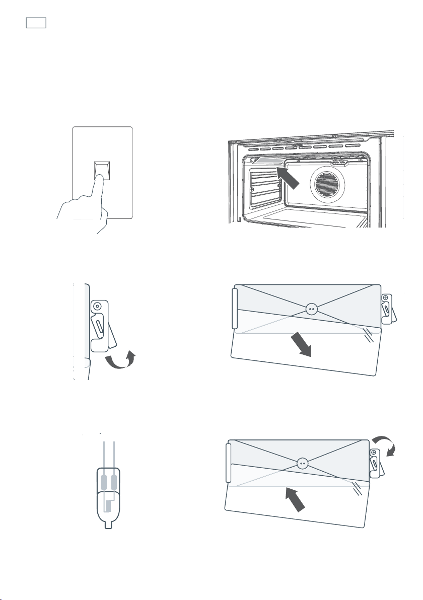
Replacing the oven light bulbs
The oven light bulbs (12V/20 W halogen) have a very long life, but if you should need to replace
one, use only a replacement bulb purchased from your nearest Fisher & Paykel dealer and follow
these steps. Note: oven bulb replacement is not covered by your warranty.
1
Allow the oven to cool down, then turn
it off at the mains power supply (wall
switch).
3
Using a flat-head screwdriver, twist and
lift the retainer clip upwards to release the
glass cover. Hold the glass cover to prevent
it falling.
5
Hold the replacement bulb in a soft cloth
or tissue (touching the bulb will reduce its
life span) and insert it into the socket.
2
Remove any oven shelves that may get in
the way.
4
Carefully lift the glass cover out of the
retaining bracket in the back and pull out
the faulty bulb.
6a
Reposition the glass cover and twist the
retainer clip back in place.
6b
Turn the oven back on at the mains power
supply (wall switch).
OFF
45
Care and cleaning
Removing and replacing the door glass panes for cleaning.
Make sure you follow the precautions and instructions below very carefully. Replacing the
glass panes and the door incorrectly may result in damage to the oven and may void
your warranty.
Your oven door has 4 panes of glass. The middle and inner panes may be removed for
cleaning.
Important!
Switch the oven off at the wall before removing the door.
Take care, the oven door is heavy. If you have any doubts, do not attempt to remove the door.
Make sure the oven and all its parts have cooled down. Do not attempt to handle the parts of a
hot oven.
Take extreme care when handling the glass panes. Avoid the edges of the glass bumping against
any surface. This may result in the glass shattering.
Don’t use oven cleaners or any other harsh/abrasive cleaners, cloths, scouring pads, steel wool
or sharp metal scrapers to clean the glass surfaces. These scratch the glass and may damage its
special coating, which in turn could result in the glass cracking or shattering.
If you notice any sign of damage on any of the glass panes (such as chipping or cracks), do not
use the oven. Call your Authorised Repairer or Customer Care.
Make sure you replace all the glass panes correctly. Do not use the oven without all glass panes
correctly in place.
If the glass panes feel difficult to remove or replace, do not force them.
Call your Authorised Repairer or Customer Care for help. Note: service visits providing assistance
with using or maintaining the oven are not covered by your warranty.
A
B
C
D
inner
outer
middle
middle
46
Care and cleaning
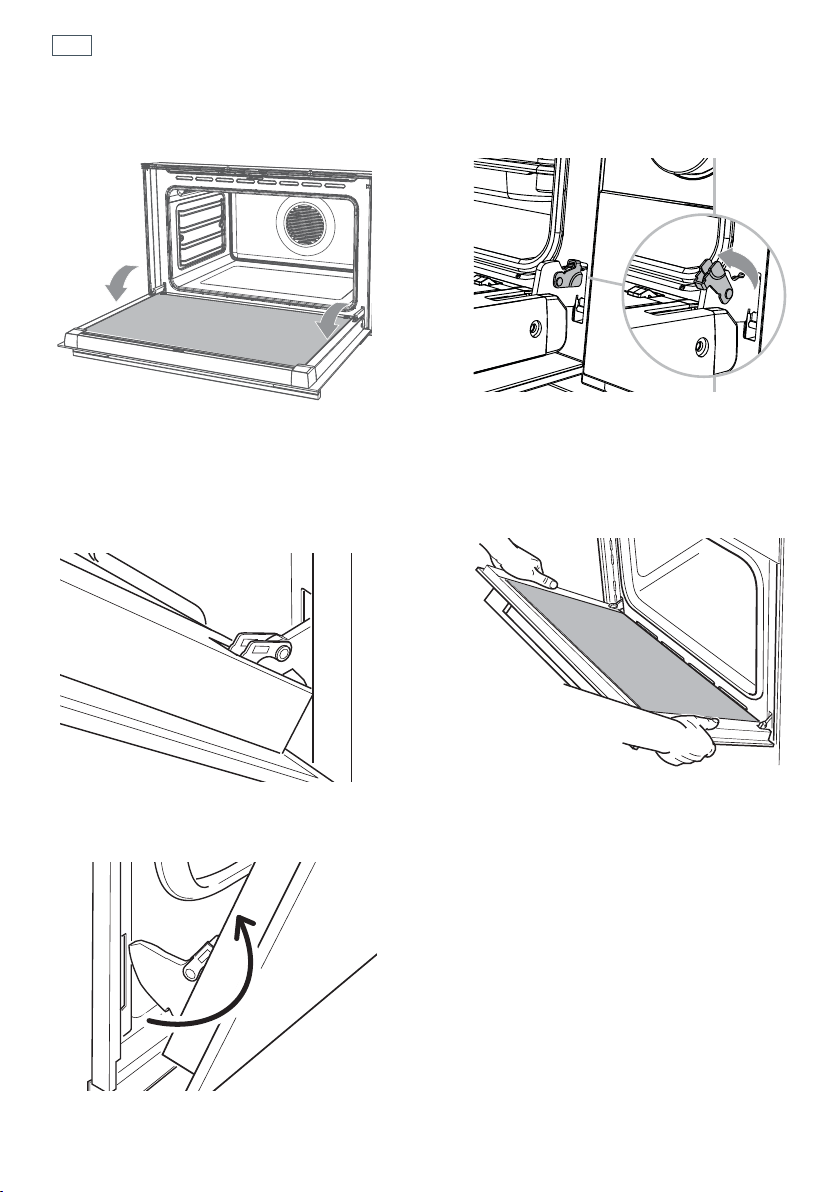
Removing the door
1a
Turn the oven off at the wall. Make sure
you have prepared enough space for
resting the door and its glass panes on a
clean, flat surface.
1b
Open the door to its full extent.
2
Open the levers on the left and right
hinges to their full extent, as shown.
3
Gently close the door until the left and
right hinge levers are hooked to the door.
5a
Lift the door and disengage the hinges.
5b
Rest the door on a soft surface. Ensure you lay
it with the handle side down.
4
Hold the door firmly, as shown.
C
47
Care and cleaning
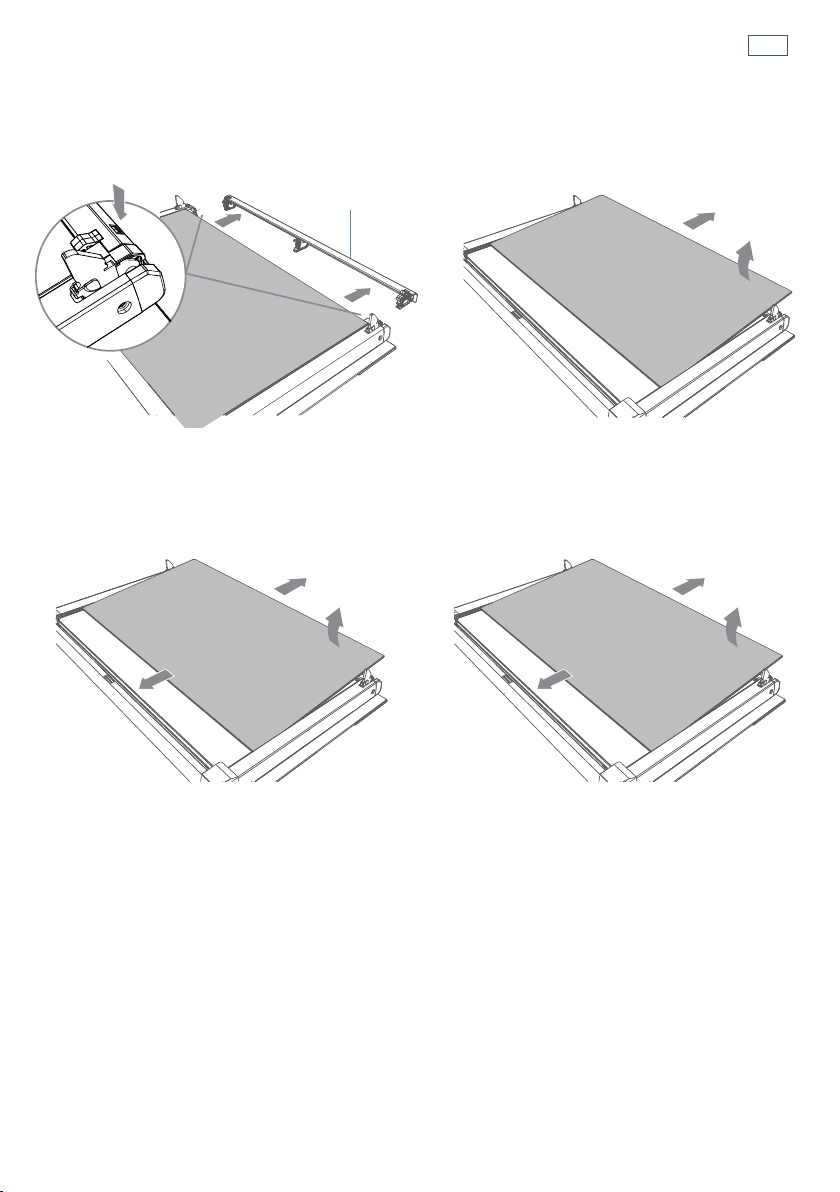
Remove the inner and middle glass panes
1
Press down on both tabs (1) to release the
glass retainer (
2).
2
Lift the inner pane (D) slightly (1), then
gently slide out (
2).
1
2
1
2
Glass retainer
3
Slide the first middle pane (C) slightly
towards yourself (
1), then lift (2) and slide
out (
3).
4
Slide the second middle pane (B) slightly
towards yourself (
1), then lift (2) and slide
out (
3).
2
1
3
2
1
3
48
Care and cleaning
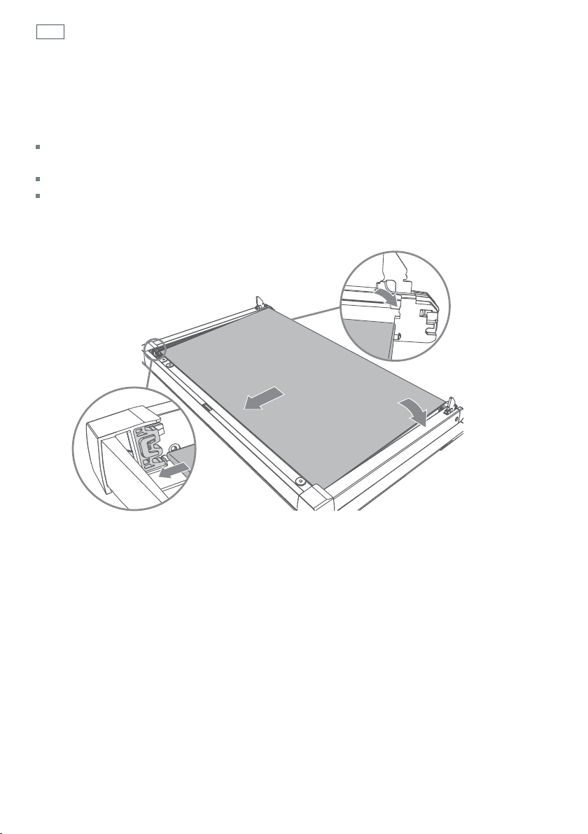
Note - the two middle panes (B and C) are identical.
1
Take the middle pane (B) and hold it firmly. Insert it in the lowest pair of grooves (1), push it
slightly towards yourself (
2) and gently lower into place (3).
2
1
3
3
After cleaning, replace the glass panes
When replacing the glass panes, make sure that:
you replace all three panes correctly, as shown. Each pane must be in the position described below
in order to fit into the door and to ensure that the oven operates safely and correctly.
you take extra care not to bump the edges of the glass against any object or surface.
you do not force any of the panes into place. If you are experiencing difficulties replacing the
panes, remove them and start the process again from the beginning. If this still does not help, call
Customer Care.
49
Care and cleaning
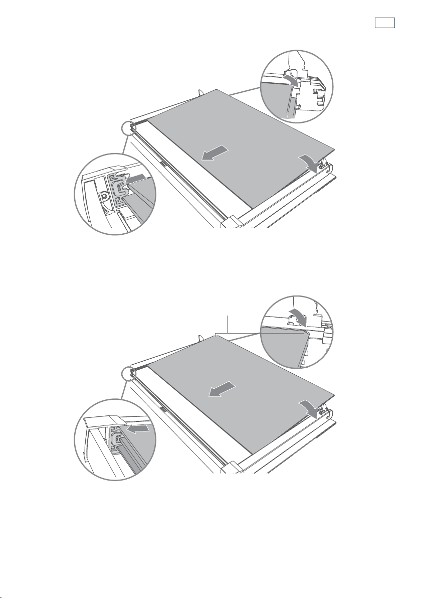
3
2
1
3
1
2
3
2
Take the other middle pane (C) and hold it firmly. Insert it in the next pair of grooves (1), push it
slightly towards yourself (
2) and gently lower into place (3).
3
Take the inner pane (D), holding it with the angle-cut corner orientated as shown. Insert it in the
uppermost pair of grooves (
1), push it slightly towards yourself (2) and gently lower into place
(
3).
Important!
Make sure that the angle-cut corner of the inner pane (D) is at the bottom of the oven door, on the left-hand
side. It has to be in this position for the door to function correctly.
Angle-cut corner
50
Care and cleaning
4
Position the glass retainer, as shown. It should sit on the bottom edge of the outer glass (A).
Check that the clamps of the glass retainer are not deformed or damaged.
5
Gently push the glass retainer back into place. You should be able to hear the tabs on both sides
click as they lock the glass retainer in.
Important!
Make sure the glass retainer is correctly and firmly in place and that the glass panes are secure.
Glass retainer
Clamp
Clamp
Glass retainer“Click”
51
Refit the door
1
Hold the door firmly.
3
Open the door to its full extent.
2
Insert the hinge tongues into the slots,
making sure that the notches on both
sides drop into place as shown.
4a
Fully close the levers on the left and right
hinges, as shown.
4b
Close the door, turn the power supply to
the oven on at the wall.
Notch
Care and cleaning
52
Care and cleaning
5
Check the door shuts completely and that the door lock (at top centre of door) is not obstructing
the door.
6
Check the door sensor (top left) is correctly operating:
start a ‘Self Clean’ cycle (see ‘Using the Self clean function’)
wait five minutes - the door lock indicator light should turn on.
after five minutes turn the function dial to O (Off).
IMPORTANT!
Do not continue with the Self Clean cycle if the side racks or shelves are in the oven.
If the door lock indicator light does not turn on, or the display shows Fdor, refer to
‘Troubleshooting’.
Sensor
Door Lock

53
Using the Self Clean function
During the pyrolytic Self Clean cycle the extremely high temperature burns off and breaks
down grime and grease deposits. All that is left is a small amount of grey ash that you can easily
remove.
You can set the Self Clean cycle time between one and a half and three hours. The heavier the
soiling, the longer the cleaning time required.
Important!
You must clean the inside glass door panel BEFORE starting a Self Clean cycle. Failure to do this
may result in permanent staining or marking of the door glass.
Do not use oven cleaners, any degreasing cleaners, or oven liners.
Make sure you remove the side racks, oven shelves and trays, rotisserie and all other bakeware
and utensils from the oven before starting a Self Clean cycle. If left in the oven, they will become
permanently discoloured or damaged; items made from combustible materials (eg wood, fabric,
plastic) may even catch fire.
The storage drawer will become warm during the Self Clean cycle. Do not store flammable items
in the storage drawer. If possible, avoid opening the drawer during the cycle, or use oven mitts to
remove items from the drawer.
Do not use your oven to clean miscellaneous parts.
Make sure the room is well ventilated.
Before starting a Self Clean cycle, make sure you move any pet birds to another, closed and well-
ventilated room. Some pet birds are extremely sensitive to the fumes given off during a Self Clean
cycle, and may die if left in the same room as the oven during such a cycle.
During a Self Clean cycle, the oven reaches higher temperatures than it does for cooking. Under
such conditions, the surfaces may get hotter than usual and children should be kept away.
The oven door will be locked during the Self Clean cycle. After the Self Clean cycle has finished,
the door will remain locked until the oven has cooled to a safe temperature. This may take up to
30 minutes.
If there are cracks or flaws on any of the oven door glass panes, if the oven seal is damaged or
worn, or if the door does not close properly, do not start a Self Clean cycle. Call your Authorised
Repairer or Customer Care.
54
Using the Self Clean function
To start a Self Clean cycle
1a
Remove oven shelves, side racks and all other accessories, bakeware, and utensils.
1b
Wipe up any spills. Failure to do so may discolour the oven surfaces.
1c
Check the inner glass pane of the oven door (D). If it has soiling on it (eg stains from greasy
splatter), you will need to clean it manually before starting a Self Clean cycle. For instructions,
see ‘Care and cleaning’.
Important!
If soiling is left on the glass, it will become burnt on during the Self Clean cycle, making it very difficult to
remove.
2
Close the oven door firmly.
55
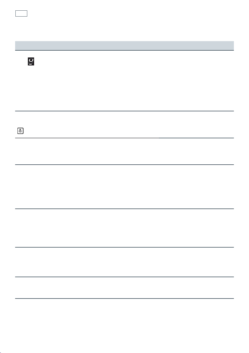
Using the Self Clean function
3
Select the Self Clean Function
The display will show
The
P will flash.
4
Adjust the cycle time (optional)
You may set the time between 1-1/2 hours (P1:30 and 3 hours (P3:00). For heavy soiling use
a longer time.
Press the
button - the P will go out.
Use the
and buttons to change the time.
After a few seconds the
P will start to flash again. Alternatively, press the Start button
to confirm and the
P will flash.
5
Start the cycle
Press the Start
button. The P will stop flashing.
The oven will come on and the
indicator will show in the display.
After a few seconds the door will lock and the door lock indicator light will come on.
The display will start to count down.
Note: If the door is not shut completely, after a few minutes the oven will switch off, the display
will show ‘Fdor’ and the oven will beep. See ‘Troubleshooting’.
6
At the end of the Self Clean cycle
The oven will turn off.
The display will show
P:00 and a flashing A
7
Turn the function dial to O (Off).
The door will remain locked.
The door lock indicator will remain on.
The display will show ‘hot’.
When the oven has cooled to a safe temperature, the door lock indicator will go out and the
door will unlock. The display will show the time of day. This may take 30 minutes.
Note: The oven will still be very warm. To avoid burns, wait for the oven to cool completely
before wiping out the ash and replacing side racks and shelves.
To cancel a Self Clean cycle
Turn the function dial to O (Off).
Note: The oven door will remain locked until the oven has cooled to a safe temperature. The door
lock indicator light will remain on, and the display will show ‘hot’.
P
1:30
A
56
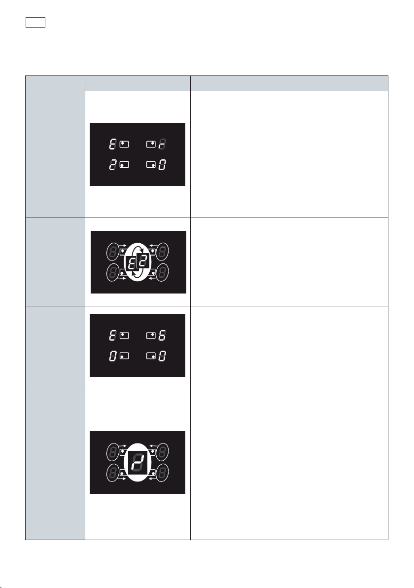
Error codes on the cooking zones display
Error code Example What to do
Erxx
or
Ex
(not E2 or EH)
or
display
not operative
1 Switch off the cooker and disconnect it from the
mains.
2 Wait for about 1 minute, then reconnect the
cooker and turn on the cooking zones.
3 Wait for about 1 minute and if the error message
does not appear again the cooking zones can be
used.
4 If the error message does not disappear repeat
step from 1 to 3.
5 If the problem continues do not use the
induction cooktop (only use the oven) and
contact your Authorised Service Centre.
E2
or
EH
‘E’ and ‘2’ alternating for one or more cooking
zones.
This indicates an overheating of the cooking
zone/s.
1 Switch off the cooking zone/s and leave to cool.
2 If the problem continues do not use the
induction cooktop (only use the oven) and
contact your Authorised Service Centre.
E6
or
display
not operative
The cooker has been incorrectly connected.
The appliance should be connected to the
appropriate power supply by a qualified
technician.
Symbol
as per
side
gure
This indicates an incorrect operation of one or
more cooking zone control dial.
1 Turn the cooking zone control dials to the ‘0’
(Off) position, then switch off the cooker and
disconnect it from the mains.
2 Wait for about 1 minute, then reconnect the
cooker and turn on the cooking zones.
3 Wait for about 1 minute and if the error message
does not appear again the cooking zones can be
used.
4 If the error message does not disappear repeat
step from 1 to 3.
5 If the problem continues do not use the
induction cooktop (only use the oven) and
contact your Authorised Service Centre.
Cooktop fault codes

57
Troubleshooting chart
Problem Possible causes What to do
The cooktop cannot be
turned on.
No power. Make sure the cooker is
connected to the power supply
and that it is switched on at the
wall. Check whether there is
a power outage in your home
or area. If you’ve checked
everything and the problem
persists, call your Authorised
Service Centre or Customer
Care.
The glass is being
scratched.
Rough-edged cookware.
Unsuitable, abrasive scourer or
cleaning products being used.
Use cookware with flat and
smooth bases. See ‘Choosing
the right cookware’.
See ‘Care and cleaning’.
Some pans make
crackling or clicking
noises.
This may be caused by the
construction of your cookware
(layers of different metals
vibrating differently).
This is normal for induction
cookware and does not indicate
a fault.
The cooktop makes a low
humming noise when
used on a high heat
setting (especially
PowerBoost).
This is caused by the technology
of induction cooking.
This is normal, but the
noise should quieten down
or disappear completely
when you decrease the
heat setting.
Fan noise coming from
the cooktop.
A cooling fan built into
your cooktop has come on
to prevent the electronics
from overheating. It may
continue to run even after
you’ve turned the cooktop
off.
This is normal and needs
no action. Do not switch
the power to the cooktop
off at the wall while the
fan is running.
Troubleshooting
58
Troubleshooting
Troubleshooting chart
Problem Possible causes What to do
Pans do not become hot
and
appears in the
display.
The cooktop cannot detect the
pan because it is not suitable for
induction cooking.
The cooktop cannot detect the
pan because it is too small for
the cooking zone or not
properly centred on it.
Use cookware suitable for
induction cooking. See
section ‘Choosing the right
cookware’.
Centre the pan and make
sure that its base matches
the size of the cooking
zone.
The fan comes on when I
select the Light function
.
This is normal.
The oven door does not
open after a Self Clean
cycle.
The oven is too hot for the door to be
opened safely.
When the oven has cooled to a safe temperature the door will
automatically unlock and the door lock indicator will go out.
The display shows 12.00
and I cannot open the
oven door or adjust the
time.
There has been a power interruption during a Self Clean cycle.
When the power is restored the door will remain locked until the
oven has cooled to a safe temperature.
When the oven has cooled the door will unlock and the display
will flash
12.00
.
You can then reset the clock and use the
oven.
The display shows
Fdor
The door has not shut completely (Self clean function) or the Self
Clean function has failed.
Close the door firmly and try re-starting the Self Clean cycle.
If the display still shows ‘Fdor’ try turning off the oven at the
wall. If the error persists when you turn it back on, call Customer
Care or your Authorised Service Centre
The display shows Fdor
when I do a test Self
Clean after removing the
door for cleaning.
The door has been incorrectly replaced after cleaning. Remove
and replace the door and retest. It the error still persists call
Customer Care or your Authorised Service Centre.
I replaced the door after
cleaning but it does not
shut properly.
The door lock is obstructing the door.
Remove and replace the door again. If this does not help, call
Customer Care or your Authorised Service Centre.

59
Warranty and service
Before you call for service or assistance ...
Check the things you can do yourself. Refer to the installation instructions and your user guide
and check that:
1
your product is correctly installed
2
you are familiar with its normal operation.
If after checking these points you still need assistance, please refer to the Service & Warranty
book for warranty details and your nearest Authorised Service Centre, or contact us through our
local website www.fisherpaykel.com.
This cooker has been designed and constructed in accordance with the following
codes and specifications:
In New Zealand and Australia:
AS/NZS 60335-1 General Requirements for Domestic electrical appliances
AS/NZS 60335-2-6 Particular Requirements for Domestic electrical cooking appliances
AS/NZS CISPR 14.1:2010 Electromagnetic Compatibility Requirements.
Product details
Fisher & Paykel Ltd
Model Serial No.
Date of Purchase Purchaser
Dealer Suburb
Town Country


NZ AU 07.2013F&P PN - 590581 A F&P ITALY PN - 1104283-ß1
www. sherpaykel.com
Copyright © Fisher & Paykel 2013. All rights reserved.
The product specifications in this booklet apply to the specific products
and models described at the date of issue. Under our policy of continuous
product improvement, these specifications may change at any time. You
should therefore check with your Dealer to ensure this booklet correctly
describes the product currently available.