Loading ...
ae,
mm
DPLS1
Drain
Panel
Level
Sensor/Control
GA
&
Di
A
MONDBACK
Protected
under
one
or
more
patents
©
2011
Mitsubishi
Electric
&
Electronics
USA,
Inc.
ee
eee
eee
eee
eee
ee
eee
eee
ee,
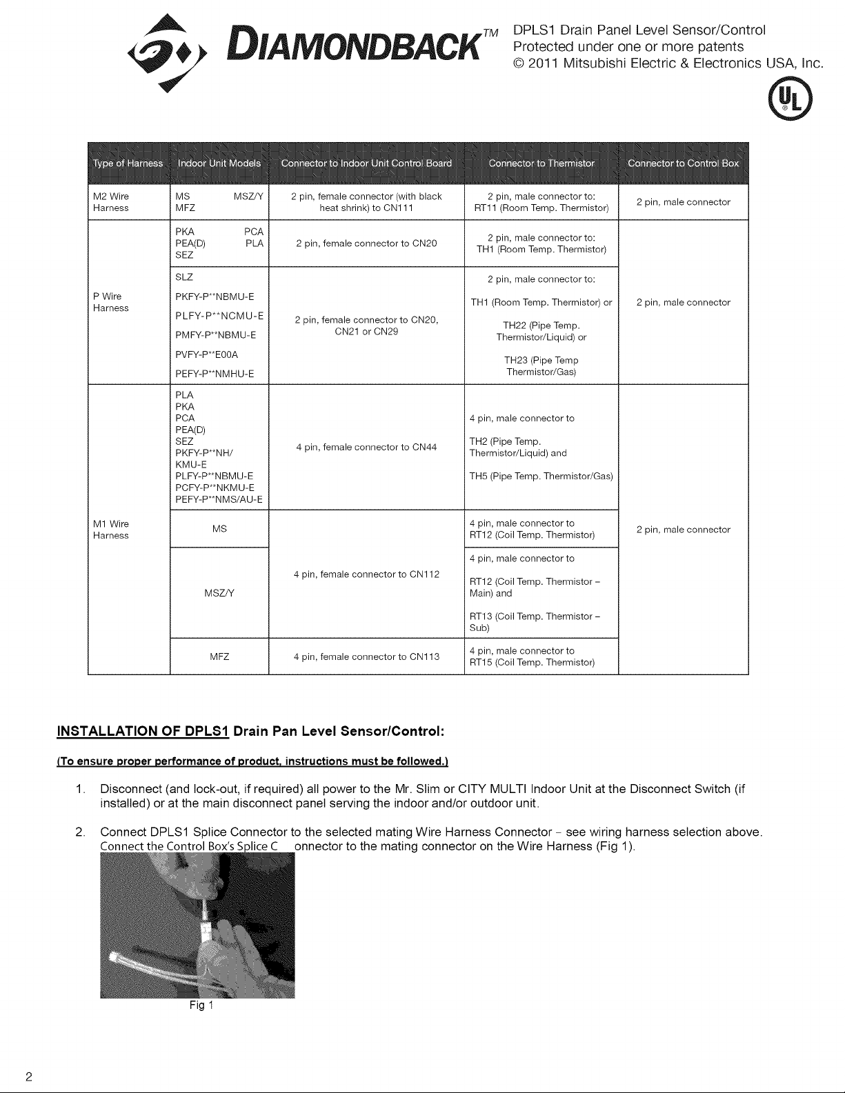
Connector
to
Control
Box
M2
Wire
MS
MSZ/Y
2
pin,
female
connector
(with
black
2
pin,
male
connector
to:
2
pin.
male
connector
Harness
MFZ
heat
shrink)
to
CN111
RT11
(Room
Temp.
Thermistor)
pin,
PKA
PCA
2
pin,
male
connector
to:
oe
PLA
2
pin,
female
connector
to
CN20
TH1
(Room
Temp.
Thermistor)
SLZ
2
pin,
male
connector
to:
na
PKFY-PNBMU-E
TH1
(Room
Temp.
Thermistor)
or
2
pin,
male
connector
PLFY-P**NCMU-E
2
pin,
female
connector
to
CN20,
.
CN21
or
CN29
TH22
(Pipe
Temp.
PMFY-P*NBMU-E
Thermistor/Liquid)
or
PVFY-P"EOOA
TH23
(Pipe
Temp
PEFY-P“*NMHU-E
Thermistor/Gas)
PLA
PKA
PCA
4
pin,
male
connector
to
PEA(D)
SEZ
.
TH2
(Pipe
Temp.
PKFY-P*'NH/
4
pin,
female
connector
to
CN44
Thermistor/Liquid)
and
KMU-E
PLFY-P*NBMU-E
TH5
(Pipe
Temp.
Thermistor/Gas)
PCFY-P**NKMU-E
PEFY-P**NMS/AU-E
M1
Wire
Ms
4
pin,
male
connector
to
2
pi
|
i
Harness
RT12
(Coil
Temp.
Thermistor)
pin,
male
CONNECIOF
4
pin,
male
connector
to
4
pin,
female
connector
to
CN112
. .
RT12
(Coil
Temp.
Thermistor
-
MSZ/Y
Main)
and
RT13
(Coil
Temp.
Thermistor
-
Sub)
4
pin,
male
connector
to
MFZ
4
pin,
female
connector
to
CN113
AT15
(Coil
Temp.
Thermistor)
INSTALLATION
OF
DPLS1
Drain
Pan
Level
Sensor/Control:
(To
ensure
proper
performance
of
product,
instructions
must
be
followed.)
1.
Disconnect
(and
lock-out,
if
required)
all
power
to
the
Mr.
Slim
or
CITY
MULTI
Indoor
Unit
at
the
Disconnect
Switch
(if
installed)
or
at
the
main
disconnect
panel
serving
the
indoor
and/or
outdoor
unit.
2.
Connect
DPLS1
Splice
Connector
to
the
selected
mating
Wire
Harness
Connector
-
see
wiring
harness
selection
above.
Connect
the
Control
Box’s
Splice
C__
onnector
to
the
mating
connector
on
the
Wire
Harness
(Fig
1).
Fig
1
Loading ...
Loading ...
Loading ...