1
DLP
®
Proje ctor
MP-WU9 1 0 1 B
Use r's M anual (det ailed)
Ope rating Guide
Thank you for purchasing this projector.
►Before using this product, read all manuals for this product.
Be sure to read Safety Guide rst. After reading them, store them in a safe
place for future reference.
WARN I N G
NOT E
Various symbols are used in this manual. The meanings of these symbols are
described below.
About this manual
WARN I N G
CAUTION
This symbol indicates information that, if ignored, could possibly
result in personal injury or even death due to incorrect handling.
This symbol indicates information that, if ignored, could possibly
result in personal injury or physical damage due to incorrect handling.
Refer to the pages written following this symbol.
NOT I CE This entry notices of fear of causing trouble.
• The information in this manual is subject to change without notice.
• The illustrations in this manual are for illustrative purposes. They may differ
slightly from your projector.
• The manufacturer assumes no responsibility for any errors that may appear in
this manual.
• The reproduction, transfer or copy of all or any part of this document is not
permitted without express written consent.

2
Contents
Int roduction ...............3
Checking the contents of package
....3
Part names ....................4
Projector, Control panel and Indicators,
Ports, Remote control
Se t ting up .................8
Installing the lens unit ............9
Arrangement ..................10
Connecting with your devices .....13
Using the security slot ...........18
Installation of the projector .......19
Rem ot e cont rol ...........2 1
Installing the batteries ...........21
Using the REMOTE ID function. . . .22
About the remote control signal ...23
Pow er on/off ..............2 4
T urning on the power ...........24
T urning off the power ...........24
Operating ................25
Selecting an input signal .........25
Selecting an aspect ratio .........26
Adjusting the projector's angle,
Lens Shift, Zoom, Lens Centering,
and Focus
...................27
Using the automatic adjustment feature
. . 30
Other buttons ..................30
Correcting the distortion .........31
Using the EDGE BLENDING features
. . 34
Using the magnify feature ........38
Temporarily freezing the screen ...39
Temporarily blanking the screen ...39
PbyP (Picture by Picture) /
PinP (Picture in Picture) . . 40
Using the menu function .........44
Indication in OSD,
Containing items of each menu
EASY MEN U. . . . . . . . . . . . . . . 47
PI CTU RE me nu ............48
IM AGE me nu ..............5 2
IN PUT me nu ..............53
SETU P m e nu ..............54
SCREEN me nu . . . . . . . . .. . . .57
OPTI ON m enu .............5 8
NETWORK menu ...........6 2
Web Control ...............65
Ma int e na nce ..............67
Cleaning the ventilation inlet .....67
Other care ....................68
Trouble shoot ing ...........70
Related messages .............70
Regarding the indicator .........71
Resetting all settings ............72
Phenomena that may be easy to
be mistaken for machine defects
. . 73
Specications .............79

3
Introduct ion
Introduction
• Keep the original packing materials for future reshipment. Be sure
to use the original packing materials when moving the projector. Use special
caution for the lens.
NOT E
Checking t he c onte nts of pack a ge
See the Contents of package section in the User’s Manual (booklet). Your
projector should come with the items shown there. Require of your dealer
immediately if any items are missing.
►Keep small parts away from children and pets. Take care not
to put in the mouth. If swallowed, consult a physician immediately for emergency
treatment.
WARN I N G
4
Introduct ion
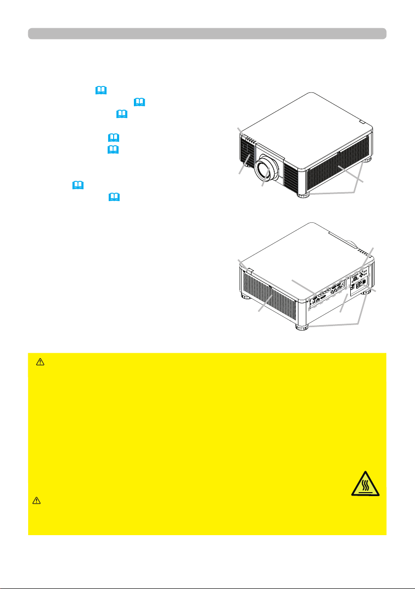
Par t na me s
Projec t or
(1) Mount cap (
19)
(2) Adjustable foot (x4) (27)
(3) Remote sensor (23, 61)
(4) Ventilation inlet
(5) Control panel (5)
(6) AC (AC inlet) (19)
(7) Ventilation inlet
(8) Ventilation outlet
(9) Ports (6)
(10) Security slot (18)
►Do not open or remove any portion of the product, unless
the manuals direct it.
►Do not subject the projector to unstable conditions.
►Do not apply a shock or pressure to this product. Remove all the attachments
including the power cord and cables, from the projector when carrying the
projector.
►Do not look into the lens and the openings on the projector while the light
source is on since the projection ray may cause a trouble on your eyes.
►Keep any object away from concentrated projection light beam. Blocking the
beam by something causes high temperature and could result in re or smoke.
►Do not touch around the ventilation outlet during use or just after use,
since it is too hot.
WARN I N G
►Do not attach anything onto the lens except the lens
cover of this projector because it could damage the lens, such as melting the
lens.
CAUT I ON
(continued on next page)
(1)
(2)
(2)
(3)
(4)
(5)
(6)
(8)
(9)
(3)
(7)
(10)
5
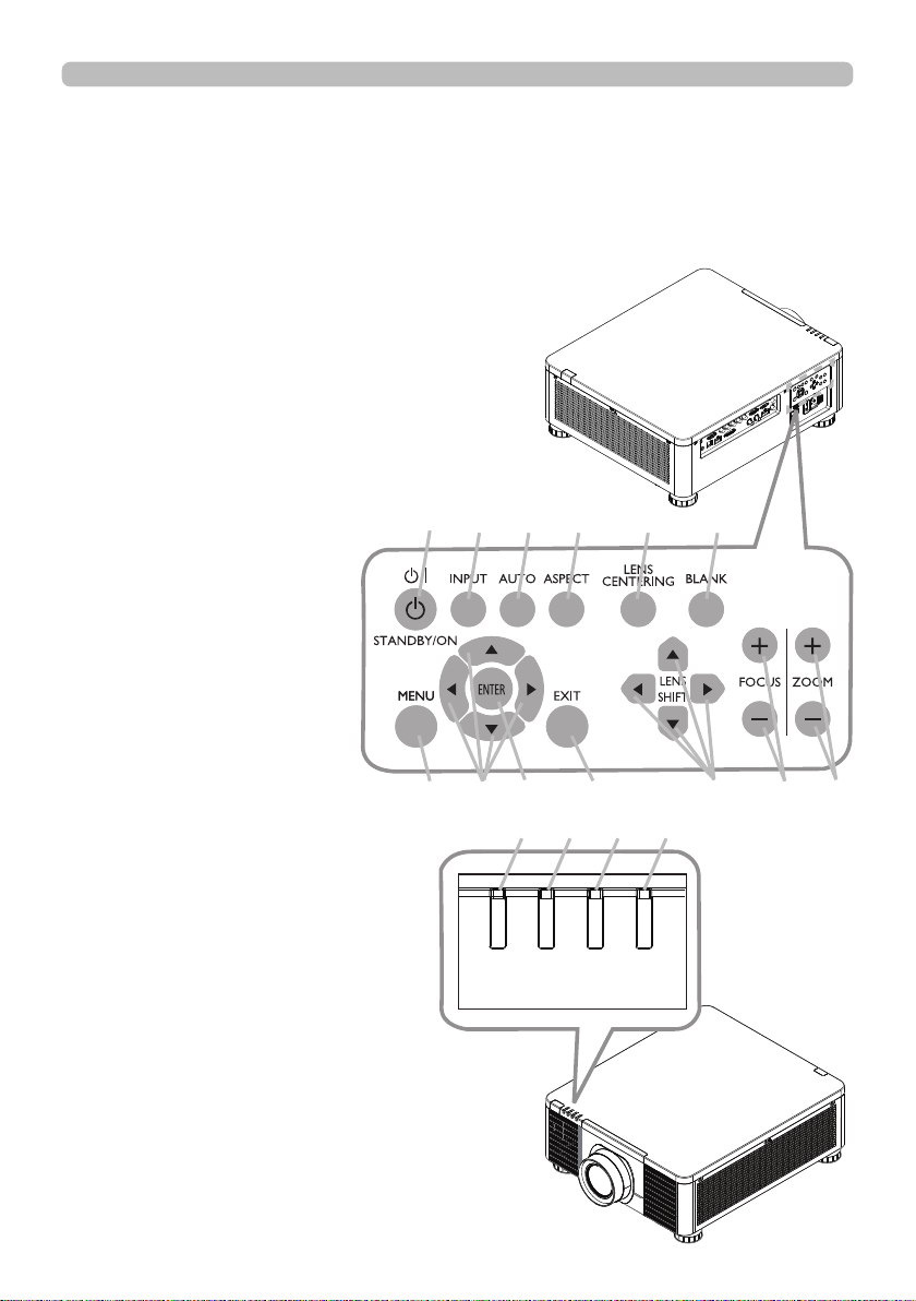
Cont rol pane l and Indic ators
(1) STANDBY/ON button
(2) INPUT button
(3) AUTO button
(4) ASPECT button
(5) LENS CENTERING button
(6) BLANK button
(7) MENU button
(8) ▲/▼/◄/► cursor buttons
(9) ENTER button
(10) EXIT button
(11) LENS SHIFT button
(12) FOCUS button
(13) ZOOM button
(14) POWER indicator
(15) STATUS indicator
(16) LIGHT indicator
(17) TEMP. indicator
Introduct ion
Part names (continued)
(continued on next page)
POWER
STATUS
LI GHT
TEMP.
(1) (2) (3) (4) (5) (6)
(7) (8) (9) (10) (11) (12) (13)
(17) (16) (15) (14)
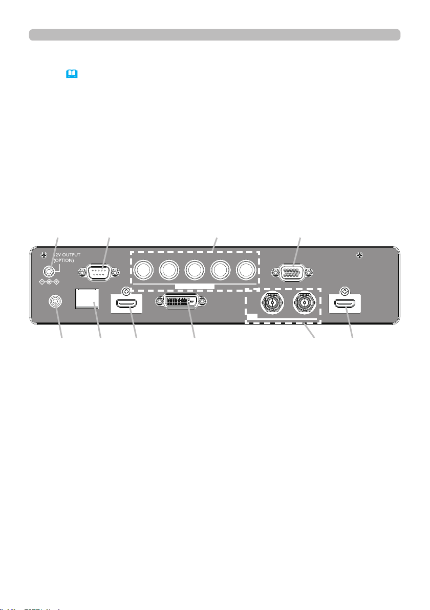
6
Port s (
13~17)
(1) COMPUTER IN1 port
(2) COMPUTER IN2 port
(3) CONTROL port
(4) HDBaseT/LAN port
(5) HDMI 1 port
(6) HDMI 2 port
(7) DVI-D port
(8) SDI IN/OUT port
(9) REMOTE CONTROL port
(10) 12V OUTPUT (OPTION) port
Introduct ion
Part names (continued)
LAN
INOUT
SDI
COMPUTER IN 2
REMOTE
CONTROLHDBaseTHDMI 1DVI-DHDMI 2
CONTROLVH
B/Cb/Pb
G/YR/Cr/PrCOMPUTER IN 1
(10) (3) (2) (1)
(9) (4) (5) (7) (8) (6)
(continued on next page)
7
Introduct ion
Part names (continued)
• Any button marked with “*” is not supported on this projector (70).
• Some keys are unavailable when OSD MESSAGE is set to INHIBIT(
56).
NOT E
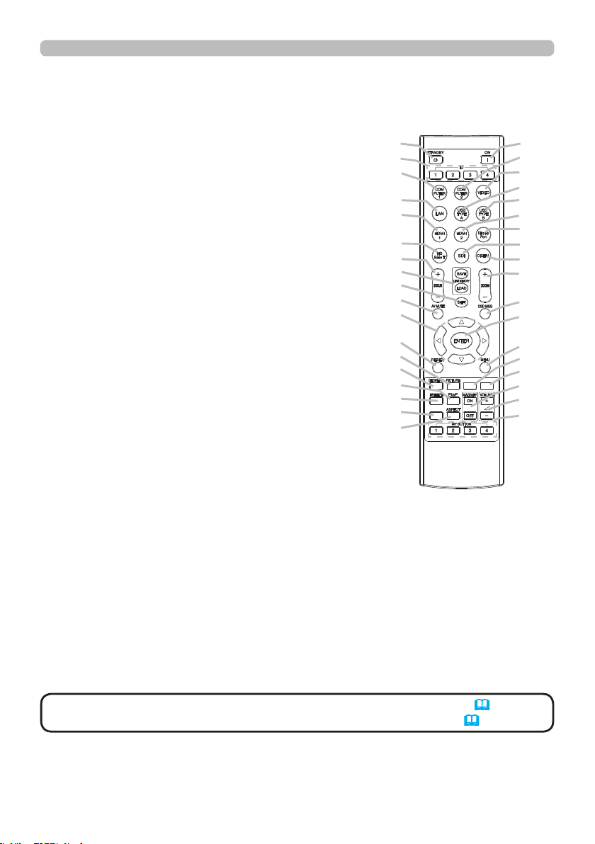
Rem ot e cont rol
(1) STANDBY button
(2) ON button
(3) VOLUME + / - buttons *
(4) AV MUTE button
(5) COMPUTER 1 button
(6) COMPUTER 2 button
(7) VIDEO button *
(8) LAN button *
(9) USB TYPE A button *
(10) USB TYPE B button *
(11) HDMI 1 button
(12) HDMI 2 button
(13) Display Port button *
(14) HDBaseT button
(15) SDI button
(16) DIGITAL button
(17) FOCUS + / - button
(18) LENS MEMORY SAVE / LOAD button
(19) SHIFT button
(20) ZOOM + / - buttons
(21) GEOMETRY button
(22) ASPECT button
(23) PICTURE button
(24) FREEZE button
(25) PbyP button
(26) MAGNIFY ON / OFF buttons
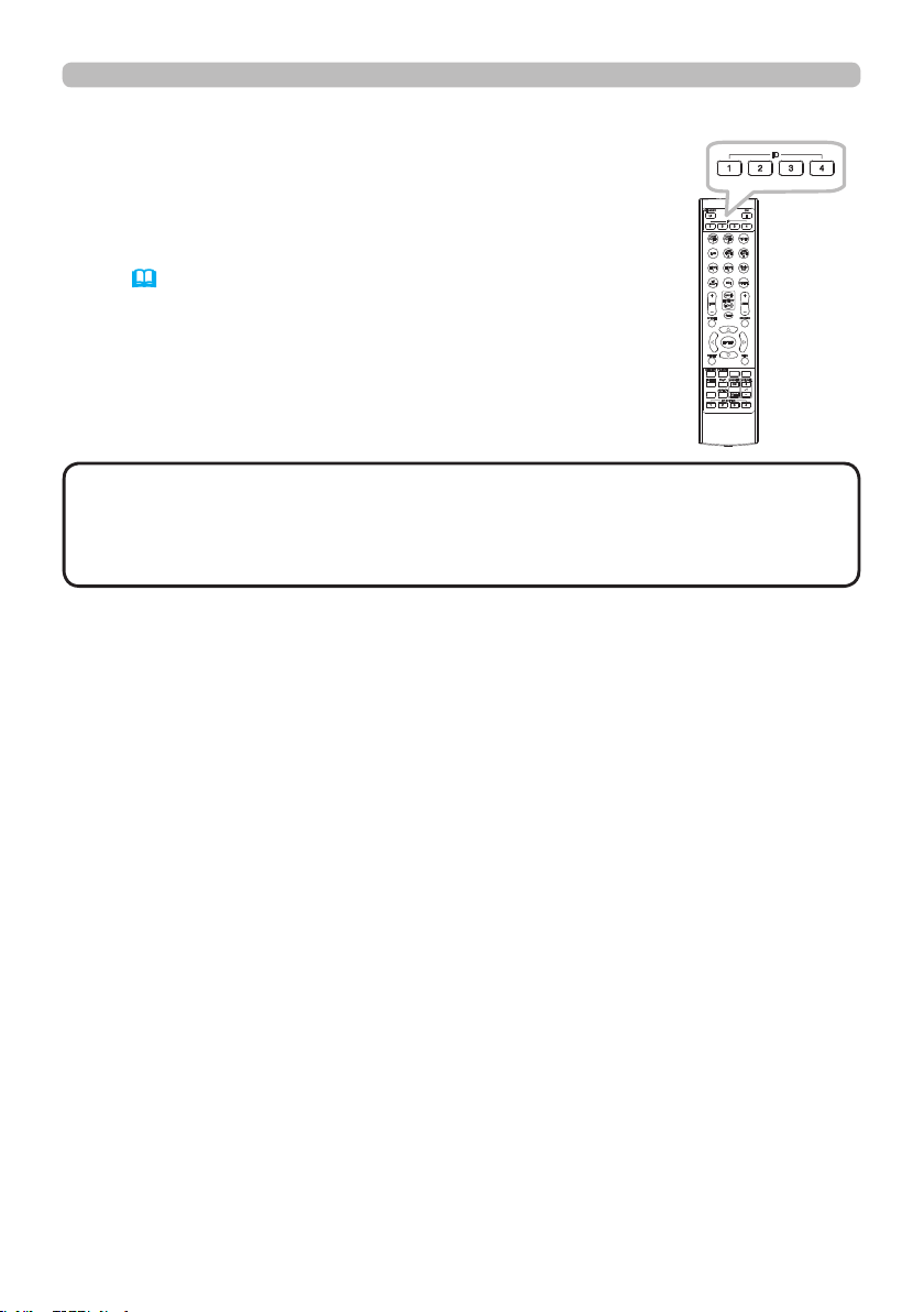
(27) MY BUTTON - 1 / 2 / 3 / 4 buttons
(28) MENU button
(29) RESET button
(30) ENTER button
(31) ▲/▼/◄/► cursor buttons
(32) ID-1 / 2 / 3 / 4 buttons
(33) OSD MSG button
(34) NETWORK button
(35) INTERACTIVE button *
(36) INFO button
(2)
(6)
(7)
(9)
(10)
(12)
(13)
(15)
(16)
(20)
(33)
(30)
(28)
(34)
(35)
(26)
(3)
(27)
INFO
NETWORK
INTERACTIVE
(1)
(32)
(5)
(8)
(11)
(14)
(17)
(18)
(19)
(4)
(31)
(29)
(23)
(21)
(25)
(24)
(36)
(22)
8
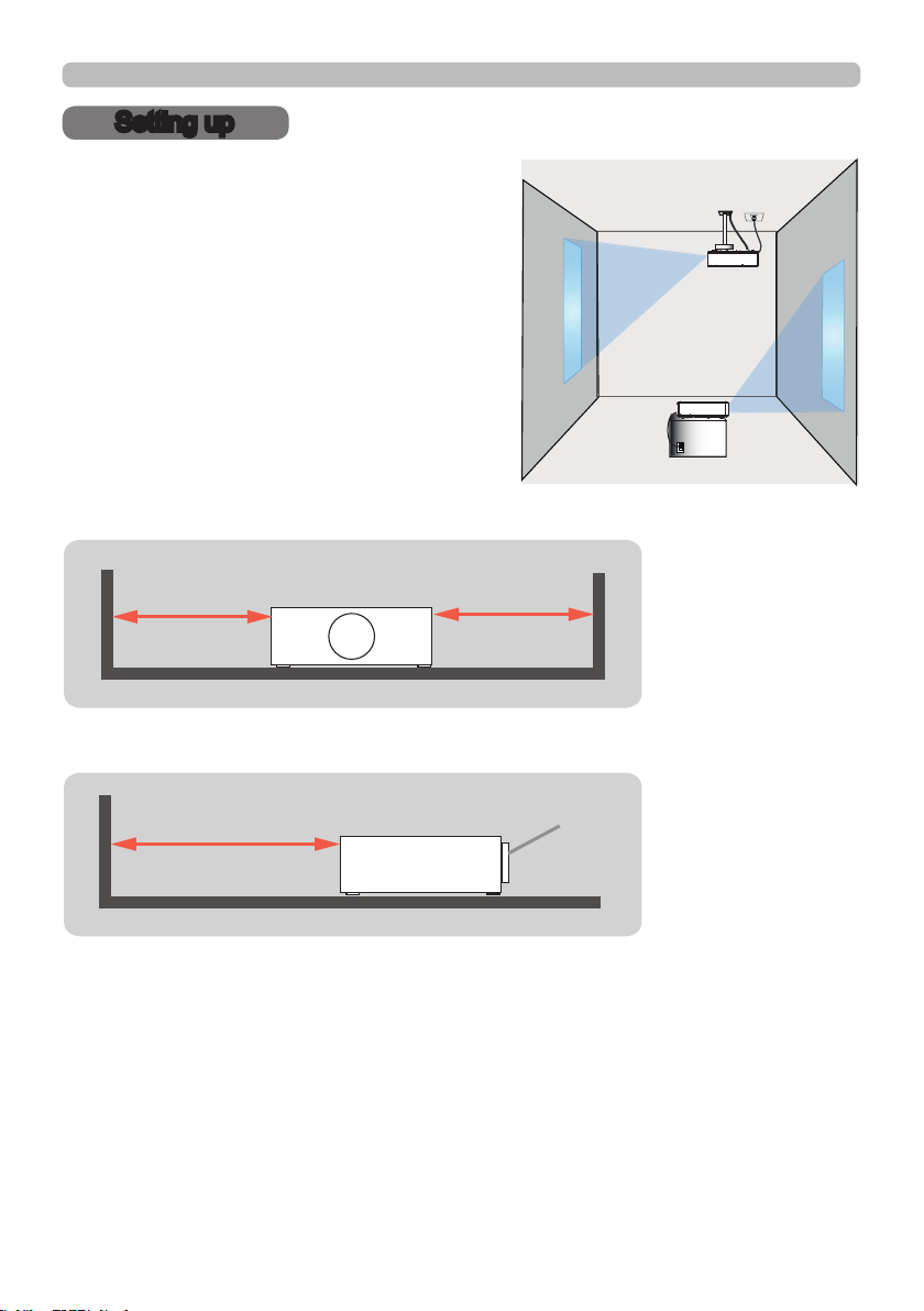
Sett ing up
Setting up
Install the projector according to the
environment and manner the projector will be
used in.
For the case of installation in a special state
such as ceiling mount, the speci ed mounting
accessories and service may be required.
Before installing the projector, consult your
dealer about your installation.
When there are the obstacles on both sides of the projector.
When there are the obstacles behind the projector.
30cm or greater 30cm or greater
50cm or greater
(continued on next page)
Lens
9
Inst alling the lens unit
See the manual of the optional lens.
Sett ing up
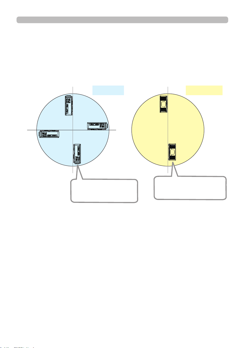
Positioning Precautions
Although this projector can be installed in 360° range (including Portrait), life of
optical parts will be shorten in the following situation:
1. If the projector is installed with the lens facing downward.
2. If the projector is installed with the IO ports side facing upward at the Portrait
situation.
270°
90°
0°
180°
Tilt position
Portrait position
Installing the projector with
the lens facing downward
is not recommended.
Installing the projector with
the IO ports side facing
upward is not recommended.

10
Sett ing up
Arra ngem ent
Refer to "Throw distance" in User’s Manual (booklet) for details.
Ⓗ×Ⓥ:
Screen size
ⓐ:
Projection distance (from the front of the projector unit)
Projector top
Projector bottom
NOT E • The installation position and the operating environment such as
temperature, altitude may affect the brightness of the display.
(continued on next page)

11
Sett ing up
Arrangement (continued)
WARN I N G
(continued on next page)
►Install the projector where you can access the power
outlet easily. If an abnormality should occur, unplug the projector urgently.
Otherwise it could cause a re or electric shock.
►Do not subject the projector to unstable conditions. If the projector falls
or topples over, it could result in injury or damage to the projector and the
surrounding things. Using a damaged projector could result in a re and an
electric shock.
• Do not place the projector in unstable places, such as an inclined surface,
places subject to vibration, on top of a wobbly table or cart, or a surface that is
smaller than the projector.
• Do not put the projector on its side, front or rear position.
• Do not attach nor place anything on the projector unless otherwise specied in
the manual.
• Do not use any mounting accessories except the accessories specied by the
manufacturer. Read and keep the manuals of the accessories used.
• For special installation such as ceiling mounting, be sure to consult your dealer
beforehand.
• It is possible to install the projector for any direction with specied mounting
accessories. Consult with your dealer about such a special installation.
• DLP chip(s) is/are precision-made parts. In rare cases, pixels may be missing
or lit, but this is not a malfunction.
• Direct high-power laser beam onto the lens surface can damage the DLP
chip(s).
• Remove all the attachments including the power cord and cables, from the
projector when carrying the projector.
►Do not install the pro
jector near thermally conductive or ammable
things. Such things when heated by the projector could result in a re and burns.
• Do not place the projector on a metal stand.
►Do not place the projector where any oils, such as cooking or machine
oil, are used. Oil may harm the product, resulting in malfunction, or falling from
the mounted position.
►Do not place the projector in a place where it may get wet. Getting the
projector wet or inserting liquid into the projector could cause a re and an
electric shock, and damage the projector.
• Do not place the projector near water, such as in a bathroom, kitchen, or
poolside.
• Do not place the projector outdoors or by the window.
• Do not place anything containing liquid near the projector.
►Do not block the ventilation inlet and ventilation outlet of the projector.
If the ventilation inlet and ventilation outlet of the projector are blocked, the
accumulated inside heat may cause re.

12
Sett ing up
Arrangement (continued)
►Place the projector in a cool place with sufcient
ventilation. The projector may shutdown automatically or may malfunction if its
internal temperature is too high.
Using a damaged projector could result in a re and an electric shock.
• Do not place the projector in direct sunlight or near hot objects such as heaters.
• Do not place the projector where the air from an air conditioner or similar unit
will blow on it directly.
• Do not place the projector on carpet, cushions or bedding.
• Do not stop up, block nor cover the projector's vent holes. Do not place
anything around the projector that could be sucked in or stuck to the projector's
ventilation inlet.
• Do not place the projector at places that are exposed to magnetic elds, doing
so can cause the cooling fans inside the projector to malfunction.
►Avoid placing the projector in smoky, humid or dusty place. Placing the
projector in such places could cause a re, an electric shock and malfunction of
the projector.
• Do not place the projector near humidiers. Especially for an ultrasonic
humidier, chlorine and minerals contained in tap water are atomized and could
be deposited in the projector causing image degradation or other problems.
• Do not place the projector in a smoking area, kitchen, passageway or by the
window.
• Position the projector to prevent light from directly hitting the
projector's remote sensor.
• Do not place the product in a place where radio interference may be caused.
• Set the ALTITUDE of the SERVICE item in the OPTION menu correctly. It is
recommended to leave it at AUTO usually (
60). If the projector is used with a
wrong setting, it may cause damage to the projector itself or the parts inside.
• Keep heat-sensitive things away from the projector. Otherwise, they may be
damaged by the heat from the projector.
CAUT I ON
NOT ICE
• When the temperature inside the projector rises high, it may cause the
high rotation of the fan for cooling temporarily.
NOT E

13
Sett ing up
Connec ting w ith your device s
Before connecting the projector to a device, consult the manual of the device to
conrm that the device is suitable for connecting with this projector and prepare
the required accessories, such as a cable in accord with the signal of the device.
Consult your dealer when the required accessory did not come with the product or
the accessory is damaged.
After making sure that the projector and the devices are turned off, perform
the connection, according to the following instructions. Refer to the gures in
subsequent pages.
►Use only the appropriate accessories. Otherwise it could
cause a re or damage the projector and devices.
• Use only the accessories specied or recommended by the projector’s
manufacturer. It may be regulated under some standard.
• Neither disassemble nor modify the projector and the accessories.
• Do not use the damaged accessory. Be careful not to damage the accessories.
Route a cable so that it is neither stepped on nor pinched out.
WARN I N G
►For a cable with a core at only one end, connect the end
with the core to the projector. That may be required by EMI regulations.
CAUT I ON
• Plug-and-Play is a system composed of a computer, its operating system
and peripheral equipment (i.e. display devices). This projector is VESA DDC
2B compatible. Plug-and-Play can be used by connecting this projector to a
computer that is VESA DDC (display data channel) compatible.
- Take advantage of this feature by connecting a computer cable to the
COMPUTER IN1 port (DDC 2B compatible). Plug-and-Play may not work
properly if any other type of connection is attempted.
- Use the standard drivers in your computer as this projector is a Plug-and-Play
monitor.
• Do not turn on or off the projector while connected to a device in
operation, unless that is directed in the manual of the device. Otherwise it may
cause malfunction in the device or projector.
• The function of some input ports can be selected according to your usage
requirements.
• Be careful not to mistakenly connect a connector to a wrong port. Otherwise it
may cause malfunction in the device or projector.
- When connecting a connector to a port, make sure that the shape of the
connector ts the port.
- Tighten the screws to connect a connector equipped with screws to a port.
- Use the cables with straight plugs, not L-shaped ones, as the input ports of
the projector are recessed.
About Plug-and-Play ca pa bility
NOT E
(continued on next page)
14
Sett ing up
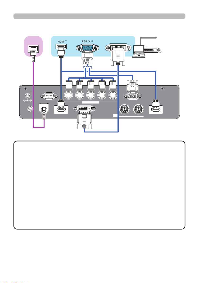
Connecting with your devices (continued)
Computer
LAN
INOUT
SDI
COMPUTER IN 2
REMOTE
CONTROLHDBaseTHDMI 1DVI-DHDMI 2
CONTROLVH
B/Cb/Pb
G/YR/Cr/PrCOMPUTER IN 1
12V OUTPUT
(OPTION)
HDBaseT
TM
DVI
• Before connecting the projector to a computer, consult the computer’s
manual and check the compatibility of the signal level, the synchronization
methods and the display resolution output to the projector.
- Some signal may need an adapter to input this projector.
- Some computers have multiple screen display modes that may include some
signals which are not supported by this projector.
- Although the projector can display signals with a resolution up to UXGA
(1600x1200) or up to W-UXGA (1920x1200), the signal will be converted
to the projector’s panel resolution before being displayed. The best display
performance will be achieved if the resolutions of the input signal and the
projector panel are identical.
• If you connect this projector and a notebook computer, you need output the
display to an external monitor, or output simultaneously to the internal display
and an external monitor. Consult the computer's manual for the setting.
• Depending on the input signal, the automatic adjustment function of this
projector may take some time and not function correctly.
NOT E
(continued on next page)

15
Sett ing up
Connecting with your devices (continued)
(continued on next page)
Computer
Access
point
External
device
LAN
INOUT
SDI
COMPUTER IN 2
REMOTE
CONTROLHDBaseTHDMI 1DVI-DHDMI 2
CONTROLVH
B/Cb/Pb
G/YR/Cr/PrCOMPUTER IN 1
12V OUTPUT
(OPTION)
► Before connecting the projector to a network system be sure
to obtain the consent of the administrator of the network.
►
Do not connect the LAN port to any network that might have the excessive voltage.
CAUT I ON
• HDBaseT is a technology to transmit image, ethernet or serial control signal
via LAN cable.
• Use LAN cables of up to 100m long. Exceeding this length, the image will be
deteriorated, and even experience malfunction on LAN transmission.
- Quali ed cable is required for HDBaseT connection.
About H DBa seT ™ conne c tion
16
LAN
INOUT
SDI
COMPUTER IN 2
REMOTE
CONTROLHDBaseTHDMI 1DVI-DHDMI 2
CONTROLVH
B/Cb/Pb
G/YR/Cr/PrCOMPUTER IN 1
12V OUTPUT
(OPTION)
Sett ing up
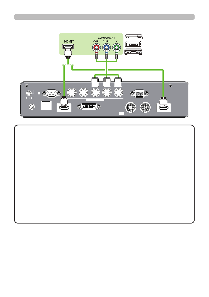
Connecting with your devices (continued)
VCR/DVD/
Blu-ray Disc
TM
player
(continued on next page)
• The HDMI ports of this model are compatible with HDCP (High-band-
width Digital Content Protection) and therefore capable of displaying video
signals from HDCP compatible DVD players or the like.
- The HDMI ports support the following signals:
For Video signals, refer to
User’s Manual (detailed) Technical
.
- This projector can be connected with another equipment that has HDMI
TM
connector, but with some equipment the projector may not work properly,
something like no video.
- Be sure to use an HDMI
TM
cable that has the HDMI
TM
logo.
- Use a Category 2-certi ed HDMI
TM
cable to input 1080p@50/60 signal to the
projector.
• The HDMI
TM
cables might come off easily due to the lack of a mechanical lock
on the cables and connectors.
・ The resolution of the signal input to the projector and signal output from the
projector may be restricted by the maximum resolution of the connected device
such as projector or monitor.
NOT E
17
Sett ing up
Connecting with your devices (continued)
LAN
INOUT
SDI
COMPUTER IN 2
REMOTE
CONTROLHDBaseTHDMI 1DVI-DHDMI 2
CONTROLVH
B/Cb/Pb
G/YR/Cr/PrCOMPUTER IN 1
12V OUTPUT
(OPTION)
SDI OUT
INFO
NETWORK
INTERACTIVE
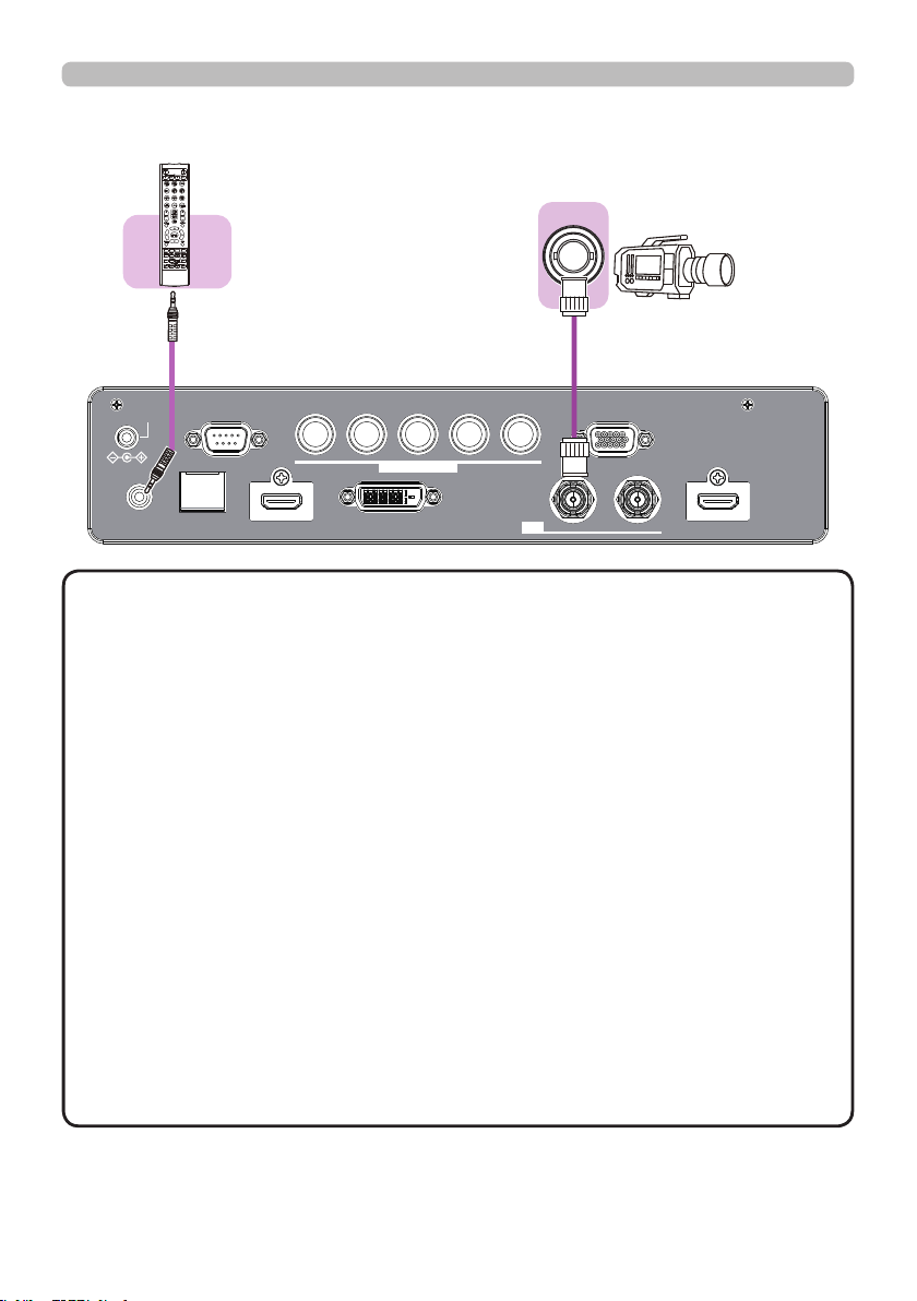
(Wired)
Remote
control
• To use a wired remote control, connect a wired remote control to
the REMOTE CONTROL port. This function is useful when a wireless remote
signal may not reliably reach the projector.
• The projector may not be operated correctly if they are operated from multiple
remote controls at the same time.
• The SDI port of this model supports the following SDI signals:
SD-SDI signal: conforming to SMPTE ST 259-C standard
YCBCR 4:2:2 10-bit
480i, 576i
Single link HD-SDI signal: conforming to SMPTE ST 292 standard
YPBPR 4:2:2 10-bit
720p@50/60, 1080i@50/60, 1080sf@25/30
3G-SDI Level-A signal: conforming to SMPTE ST 424 standard
YPBPR 4:2:2 10-bit
1080p@50/60
- This projector can be connected with another equipment that has SDI
connector, but with some equipments the projector may not work properly.
- Use a cable of 5CFB or greater (5CFB, 7CFB, etc.), or Belden 1694A or
greater to transmit the image properly. And use a cable with a length of 100m
or less.
- Setting by MENU is necessary depending on a connected device.
NOT E
18
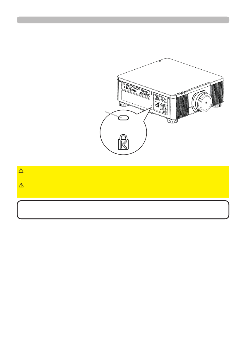
Using t he security slot
This product has the security slot for the Kensington lock.
For details, see the manual of the security tool.
►Do not use the security slot to prevent the projector from
falling down, since it is not designed for it.
WARN I N G
• The security slot is not comprehensive theft prevention measures. It
is intended to be used as supplemental theft prevention measure.
NOT E
Sett ing up
Security slot
►Do not put a cable of the Kensington lock near a ventilation
outlet to prevent it from getting hot.
CAUT I ON
19
Sett ing up
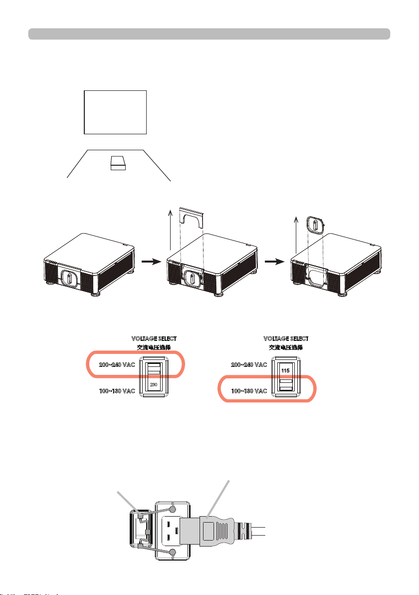
Inst allation of the projec tor
1. Installing the projector towards the screen
Screen
2. Removing the mount cap on the projector
3. Selecting the correct input voltage depending on your area
4. Connecting the power cord to the projector
Be sure that the power cord is not damaged and already connected to the power
outlet properly.
Select 200-240V
Select 100-130V
Secure the power plug by locking
the plug holder clamp.
Connect the female side of the
power cord to power input socket
of projector.
20
►Do not connect the projector to a power supply while no lens
unit is attached to it.
►Use extra caution when connecting the power cord, as incorrect or faulty
connections may result in re and/or electrical shock.
• Do not touch the power cord with a wet hand.
• Only use the power cord that came with the projector. If it is damaged, consult
your dealer to get a new one. Never modify the power cord.
• Only plug the power cord into an outlet whose voltage is matched to the power
cord. The power outlet should be close to the projector and easily accessible.
Remove the power cord for complete separation.
• Do not distribute the power supply to multiple devices. Doing so may overload
the outlet and connectors, loosen the connection, or result in re, electric shock
or other accidents.
• Connect the ground terminal for the AC inlet of this unit to the ground terminal
of the building using an appropriate power cord (bundled).
• This product is also designed for IT power systems with a phase-to
phase voltage of 220 to 240 V.
WARN I N G
NOT ICE
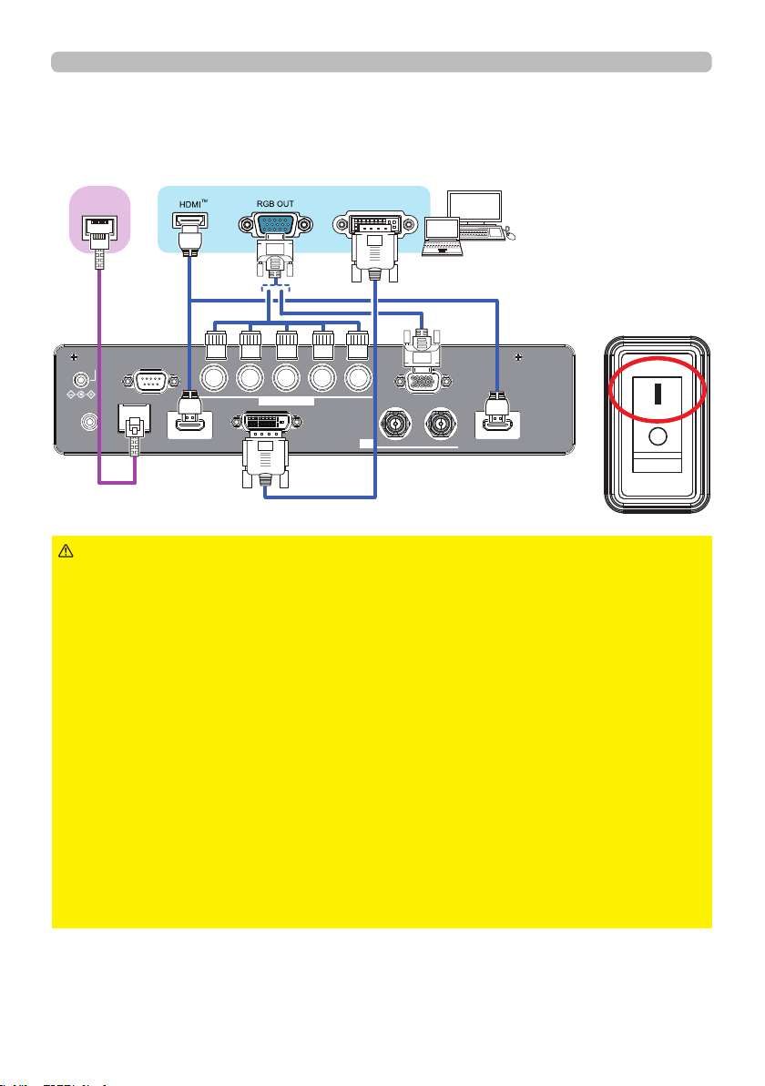
5. Connecting the projector to your PC and switching to “׀” to
turn on the power
POWER indicator turns to red, which means the projector is in standby mode.
LAN
INOUT
SDI
COMPUTER IN 2
REMOTE
CONTROLHDBaseTHDMI 1DVI-DHDMI 2
CONTROLVH
B/Cb/Pb
G/YR/Cr/PrCOMPUTER IN 1
12V OUTPUT
(OPTION)
HDBaseT
TM
DVI
Sett ing up
21
Remote control
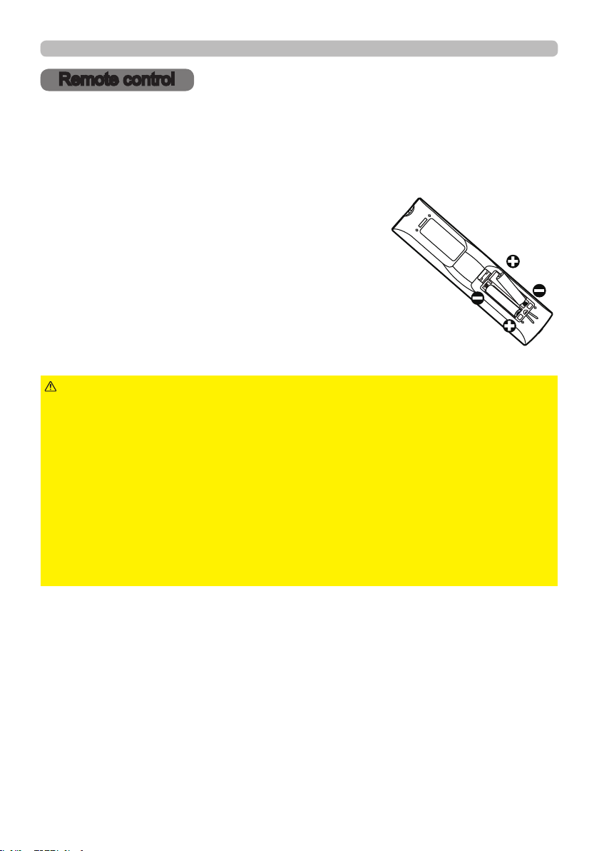
Inst alling the batt erie s
Insert the batteries into the remote control before using it. If the remote control
starts to malfunction, try to replace the batteries. If you will not use the remote
control for long period, remove the batteries from the remote control and store
them in a safe place.
1.
2.
Align and insert the two AA batteries
according to their plus and minus terminals
as indicated in the remote control. (Use
the appropriate AA carbon-zinc or alkaline
batteries (non-rechargeable) in accordance
with laws and regulations.)
3.
Put the battery cover back to the former state.
►Always handle the batteries with care and use them only as
directed. Improper use may result in battery explosion, cracking or leakage, which
could result in re, injury and/or pollution of the surrounding environment.
• Be sure to use only the batteries specied. Do not use batteries of different types at
the same time. Do not mix a new battery with used one.
• Make sure the plus and minus terminals are correctly aligned when loading a battery.
• Keep a battery away from children and pets.
• Do not recharge, short circuit, solder or disassemble a battery.
• Do not place a battery in a re or water. Keep batteries in a dark, cool and dry place.
• If you observe battery leakage, wipe out the leakage and then replace a battery.
If the leakage adheres to your body or clothes, rinse well with water immediately.
• Obey the local laws on disposing the battery.
WARN I N G
Re m ot e c ontrol
Remove the battery cover.
22
Re m ot e c ontrol
Using t he REMOTE ID func tion
Use this function to control specic projectors by the remote
control assigned the same ID number when you use multiple
projectors of the same type at the same time.
Assign an ID number to each projector before using the
REMOTE ID item in the SERVICE menu of the OPTION
menu (
61). Press the ID button with the same ID number
as assigned to the projector you are going to control. The ID
button selected will light for several seconds.
INFO
NETWORK
INTERACTIVE
• Each time you press any button (except ID buttons), the ID button of
current selected ID number will light.
• To conrm the projector's current ID, press any ID button for three seconds.
Its number will be shown on each screen regardless of set ID of projector.
NOT E
23
Re m ot e c ontrol
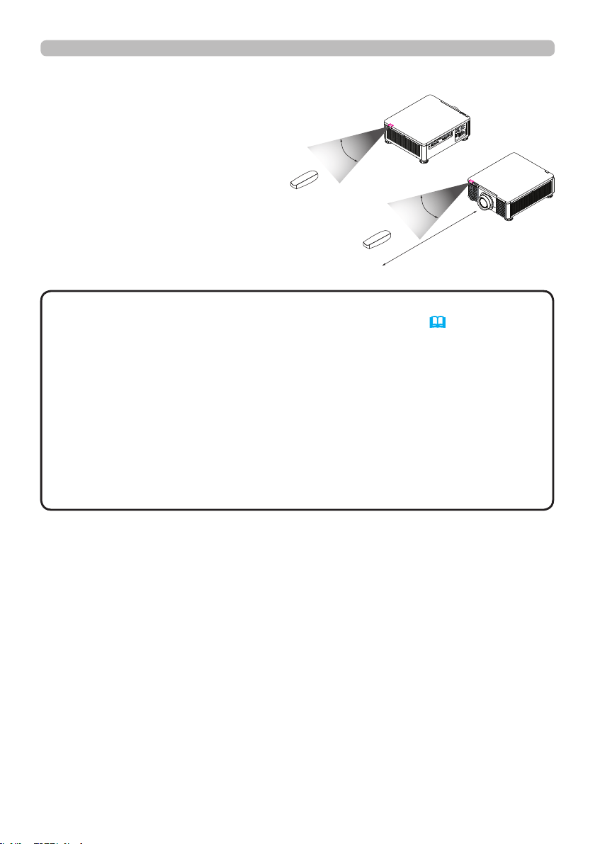
About t he rem ote cont rol signa l
The remote control works with the
projector’s remote sensor. This
projector has two remote sensors
on the front and back sides.
The sensors can sense signals
within the following range:
30 degrees (15 degrees to the
left and right of the sensor) within
about 7 meters.
• You can deactivate one of the sensors using the INFRARED
REMOTE item in the SERVICE menu of the OPTION menu (61).
• The remote control signal reected in the screen or the like may be available.
If it is difcult to send the signal to the sensor directly, attempt to make the
signal reect.
• The remote control uses infrared light to send signals to the projector (Class 1
LED), so be sure to use the remote control in an area free from obstacles that
could block the remote control’s signal to the projector.
• The remote control may not work correctly if strong light (such as direct
sunlight) or light from an extremely close range (such as from an inverter
uorescent lamp) shines on the remote sensor of the projector. Adjust the
position of projector avoiding those lights.
NOT E
(approx.)
30°
30°
7
m
24
Power on/off
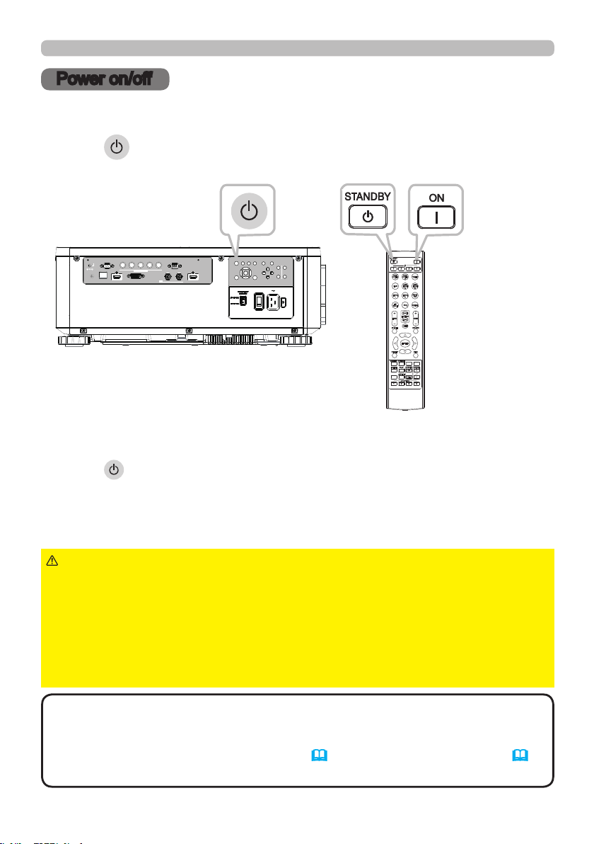
Pow e r on/off
Press the button on the projector or the ON button on the remote control to
start up the projector.
Turning on t he pow er
Turning off t he pow er
Press the button on the projector or the STANDBY button on the remote
control. The message will appear on the screen. Press the button again while the
message appears. When the projector has been turned off, the cooling fan will
remain in operation for approximately 120 seconds.
LAN
IN OUT
SDI
COMPUTER IN 2
REMOTE
CONTROL HDBaseT HDMI 1 DVI-D HDMI 2
CONTROL V H
B/Cb/Pb
G/Y R/Cr/Pr COMPUTER IN 1
EXITMENU
LENS
SHIFT
INPUT ASPECT BLANK
LENS
CENTERING
AUTO
FOCUS ZOOM
12V OUTPUT
(OPTION)
INFO
NETWORK
INTERACTIVE
►A strong light is emitted when the projector’s power is on.
Do not look into the lens of the projector or look inside of the projector through
any of the projector’s openings since the projection ray may cause a trouble on
your eyes.
►Keep any object away from concentrated projection light beam. Blocking the
beam by something causes high temperature and could result in re or smoke.
►Do not touch around the ventilation outlet during use or just after use, since it
is too hot.
WARN I N G
• Turn the power on/off in right order. Power on the projector prior to
the connected devices.
• This projector has the function that can make the projector automatically turn
on/off. Refer to the DIRECT POWER ON (58) and AUTO POWER OFF (58)
items of the OPTION menu.
NOT E
25
Ope rating
Operating
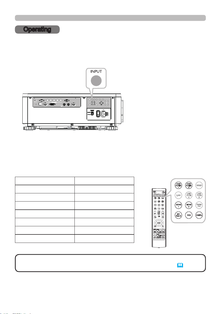
Press the INPUT button on the projector. Select a desirable input referring to the
displayed input list. Even if you press the button for an input port which is not
supported, input source list is displayed like when pressing the INPUT button.
Sele ct ing a n input signa l
LAN
IN OUT
SDI
COMPUTER IN 2
REMOTE
CONTROL HDBaseT HDMI 1 DVI-D HDMI 2
CONTROL V H
B/Cb/Pb
G/Y R/Cr/Pr COMPUTER IN 1
EXITMENU
LENS
SHIFT
INPUT ASPECT BLANK
LENS
CENTERING
AUTO
FOCUS ZOOM
12V OUTPUT
(OPTION)
Press HDMI 1, HDMI 2, COMPUTER 1, COMPUTER 2, HDBaseT, SDI or
DIGITAL button on the remote control.
The port corresponding to each button is selected as below.
INFO
NETWORK
INTERACTIVE
Button Ports
HDMI 1 HDMI 1
HDMI 2 HDMI 2
COMPUTER 1 COMPUTER IN1
COMPUTER 2 COMPUTER IN2
HDBaseT HDBaseT
SDI SDI
DIGITAL DVI-D
• While ON is selected for AUTO SEARCH item in OPTION menu, the
projector will keep checking the ports until an input signal is detected (
58).
NOT E
26
Ope rating
INFO
NETWORK
INTERACTIVE
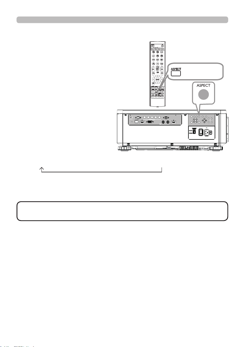
Sele ct ing a n aspe ct rat io
Press ASPECT button on the projector
or on the remote control.
Each time you press the button, the
projector switches the mode for aspect
ratio in turn.
• ASPECT button does not work when no proper signal is input.
• NORMAL mode keeps the original aspect ratio setting.
NOT E
If there is no signal
16:10 (xed)
NORMAL 4:3 16:9 16:10 ZOOM NATIVE
LAN
IN OUT
SDI
COMPUTER IN 2
REMOTE
CONTROL HDBaseT HDMI 1 DVI-D HDMI 2
CONTROL V H
B/Cb/Pb
G/Y R/Cr/Pr COMPUTER IN 1
EXITMENU
LENS
SHIFT
INPUT ASPECT BLANK
LENS
CENTERING
AUTO
FOCUS ZOOM
12V OUTPUT
(OPTION)
ASPECT button
27
Ope rating
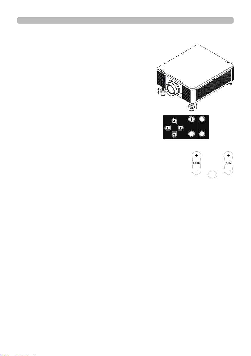
Adjust ing t he projector's a ngle , Le ns Shift , Zoom , Le ns
Ce nte ring, a nd Foc us
1. Use the adjustable feet to change the angle of
the projector in order to achieve the most suitable
angle for projection on the screen.
2. Adjusting the lens by horizontal and vertical lens
shift, and adjust Zoom and Focus of lens.
Method 1: Using the Keypad on the projector.
Method 2: Using the button on the remote control.
Press the SHIFT button on the remote
control to access Lens Shift. Use the ▲▼ ◄ ►
buttons to adjust the horizontal or
vertical position of the lens. Press FOCUS, ZOOM button then
use the ◄► buttons to adjust the focus and zoom.
The Lens shift, Zoom or Focus dialog will appear when you press the buttons of SHIFT,
ZOOM or FOCUS. Generally, better image can be got when the lens is set to the center.
Note : While the lens is moving to the center, the OSD will disappear and an
hourglass icon will appear on the screen. CENTERING may take some
time till the lens reaches to the center.
* Perform CENTERING before the projector is turned off.
* The adjustable range of LENS SHIFT varies depending on which lens is
mounted on the projector. Therefore, LENS SHIFT adjustment may not reach
the end of the indicator in the dialog. This is not a malfunction.
LENS
SHIFT
FOCUSZOOM
SHIFT
(continued on next page)
28
Ope rating
Horizontal and vertical lens shift
In addition to using the adjustable feet to adjust projection angle, you can also
use the Lens Shift function to adjust the projected picture.
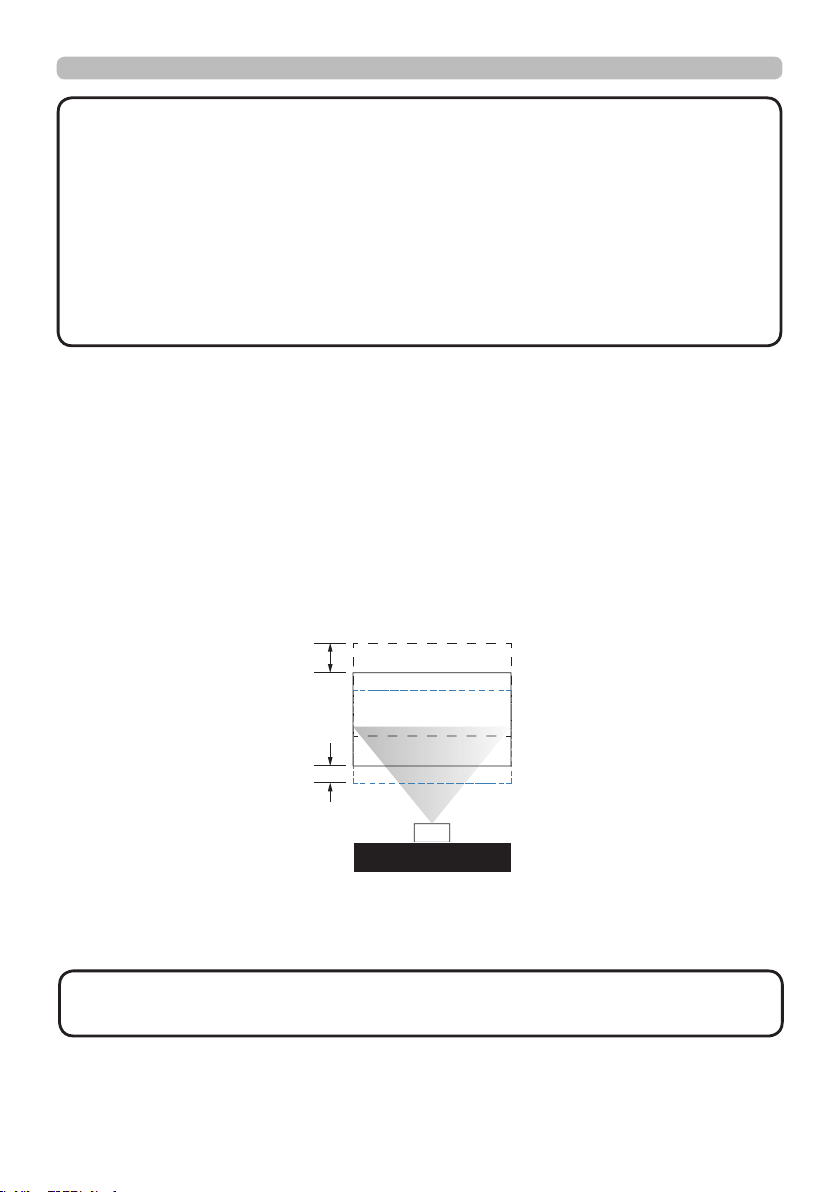
Moving the lens vertically
The distance of vertical lens shift is +60% or -22% of the screen height in both
directions. For instance, if you are using a 2.15m × 1.35m(100") screen, you will
be able to move the picture up to 81cm upwards or up to 29.7cm downwards.
Range of vertical
lens shift adjustment
Range of vertical
lens shift adjustment
This illustration shows normal vertical lens shift without the use of special speci cation lens
or projector.
· Make sure that the center of the lens is vertical to the center of the
screen. The above-described value is for SD-903 lens.
NOT E
•
Adjust the lens shift / zoom / focus 30 minutes after turning on the projector.
• Slight changes in the image position and/or focus may occur within 30 minutes
after turning on the projector. If the room temperature and humidity have
changed after adjusting the lens shift / zoom / focus, readjust as necessary.
• In anticipation of the changes after installation, set up the image size including
the margin from the screen edge.
• When adjusting the lens shift vertically, nish adjusting lens shift by moving
the projected screen upward. If you nish adjusting the lens shift by moving the
projected screen downward, the projected screen may be misaligned slightly
downward over time.
NOT E
29
Ope rating
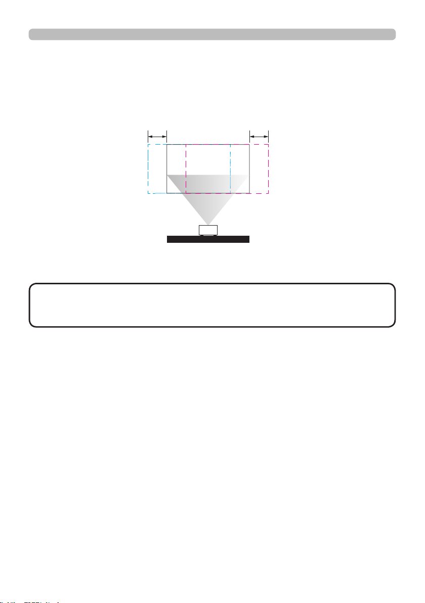
Moving the lens horizontally
The distance of horizontal lens shift is 10% of the screen width in both directions.
For instance, if you are using a 2.15m × 1.35m(100") screen, you will be able to
move the picture to the right or the left up to 21.5cm.
H: Range of Horizontal lens shift adjustment
H H
This illustration shows normal horizontal lens shift without using special speci cation lens
or projector.
· When the lens is in the neutral position (i.e. without horizontal or
vertical shift), the center of the projection should be aligned with the center of
the screen. The above-described value is for SD-903 lens.
NOT E
Lens Memory
This projector can save 3 sets of lens position information (including Focus, Zoom
and Lens shift setting). No matter how you adjust the lens, you can call these lens
memory to restore the lens position setting that you saved in the OSD.
•
Load Memory
Select this item to load your own setting for lens.
•
Save Setting
You can adjust the OSD’s color items by yourself then use this function to save
your setting for lens.
30
Ope rating
INFO
NETWORK
INTERACTIVE
Using t he a ut omat ic a djustm ent feat ure
Adjusts the signal synchronization
automatically.
LAN
IN OUT
SDI
COMPUTER IN 2
REMOTE
CONTROL HDBaseT HDMI 1 DVI-D HDMI 2
CONTROL V H
B/Cb/Pb
G/Y R/Cr/Pr COMPUTER IN 1
EXITMENU
LENS
SHIFT
INPUT ASPECT BLANK
LENS
CENTERING
AUTO
FOCUS ZOOM
12V OUTPUT
(OPTION)
• The automatic adjustment operation requires approx. 10 seconds. Also
note that it may not function correctly with some input.
• When this function is performed for a video signal, a certain extra such as a line
may appear outside a picture.
• When this function is performed for a computer signal, a black frame may be
displayed on the edge of the screen, depending on the computer model.
NOT E
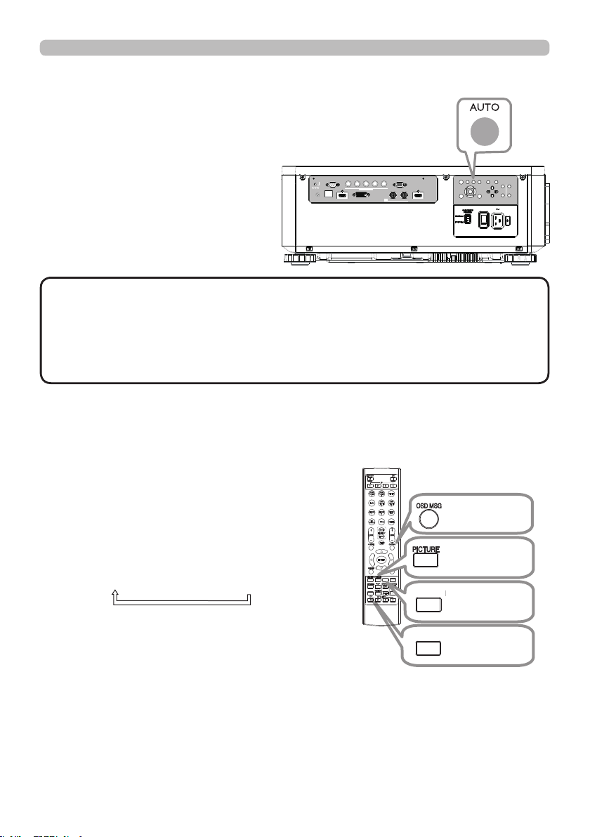
Othe r butt ons
OSD MSG: Displays the OSD MESSAGE
menu. When you press the key
for 3 seconds, the current OSD
MESSAGE setting is displayed.
Pressing the key while the setting is
displayed switches the setting in turn.
NORMAL
SILENT
INHIBIT
PICTURE: Displays the PICTURE QUALITY
menu.
INFO: Displays the INFORMATION menu.
NETWORK: Displays the NETWORK SETUP
menu.
OSD MSG
button
PICTURE
button
INFO
INFO
button
NETWORK
button
NETWORK
INTERACTIVE
31
Ope rating
KEYSTONE: allows you to adjust the vertical and
horizontal keystone.
PERFECT FIT:
allows you to adjust each of the screen
corners and sides to correct the
distortion.
WARPING:
allows you to project an image on several
types of screen.
• The menu or dialog will automatically disappear after several seconds
of inactivity. Press the GEOMETRY button again, or point the cursor at EXIT in
the dialog and press the ►or ENTER button to end the operation and close the
menu or dialog.
NOT E
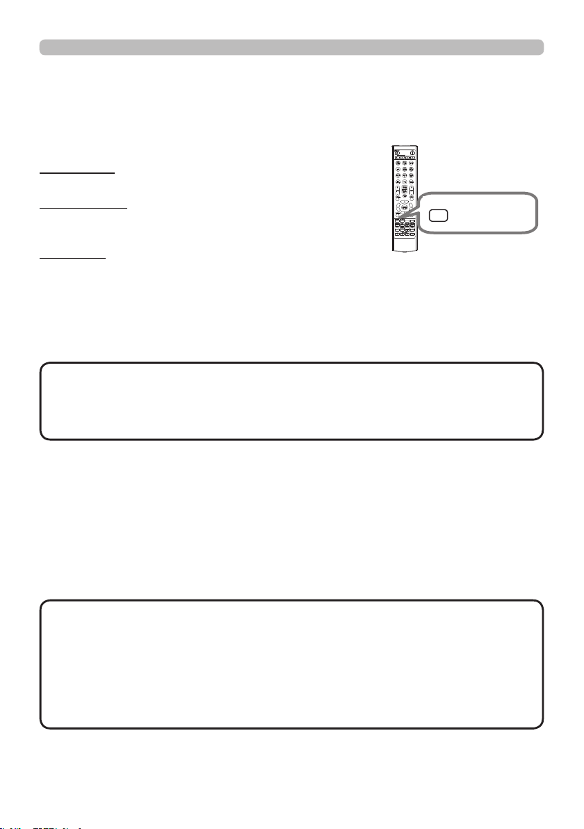
To correct the distortion of projected screen, you can select one of three options,
KEYSTONE, PERFECT FIT, and WARPING. First press the GEOMETRY button
to display the GEOMETRY CORRECTION menu, and point at one of the items
with the ▲/▼ buttons.
Corre ct ing the dist ort ion
Then follow the procedure shown below for the item you selected.
Use KEYSTONE / PERFECT FIT / WARPING for adjustment. When one of them
is selected, other items are not available.
KEYSTONE:
When KEYSTONE is pointed at, pressing the ► or ENTER button displays the
KEYSTONE dialog.
1.
Select the vertical or horizontal keystone with the ▲/▼ buttons.
2.
Use the ◄/► buttons to adjust the keystone distortion.
• When the zoom adjustment is set to the TELE (telephoto focus),
this function may be excessive. This function should be used when the zoom
adjustment is set to the full WIDE (wide-angle focus) whenever possible.
• When the horizontal lens shift is not set to the center, this function may not
work well.
• Point at RETURN in the dialog with the ▲/▼ buttons and press ◄ or ENTER
button to return to the GEOMETRY CORRECTION menu.
NOT E
INFO
NETWORK
INTERACTIVE
GEOMETRY
GEOMETRY
button

32
Ope rating
PERFECT FIT:
When PERFECT FIT is pointed at, pressing the ► or ENTER button displays
the PERFECT FIT dialog.
This projector is equipped with a test pattern for PERFECT FIT. Select
PATTERN with the
▲/▼
buttons, then press the
◄/►
buttons to switch on and
off.
1.
Select SETUP with the ▲/▼ buttons and press the ► or ENTER button.
2.
Select one of the corners or sides to be adjusted with the ▲/▼/◄/►
buttons and press the ENTER button.
3.
Adjust the selected part as below.
● For adjusting a corner, use the ▲/▼/◄/► buttons to adjust the position of
the corner.
● For adjusting the upper or lower side, use the ▲/▼ buttons to adjust the
distortion of the side.
● For adjusting the left or right side, use the ◄/► buttons to adjust the
distortion of the side.
● To adjust another corner or side, press the ENTER button and follow the
procedure from step 2.
Correcting the distortion (continued)
(continued on next page)

33
Ope rating
Correcting the distortion (continued)
4.
This projector is equipped with a memory feature for PERFECT FIT
adjustment. Up to 3 sets of adjustments can be stored.
● SAVE:
To store the current PERFECT FIT adjustment, select one of the "SAVE"
options numbered 1 to 3 (number of the memory).
Remember that the current data being stored of a memory will be lost by
saving new data into the memory.
● LOAD:
To recall stored adjustments, select one of the "LOAD" options numbered 1
to 3 (number of the memory).
Remember that the current adjusted condition will be lost by loading data. If
you want to keep the current adjustment, save it before performing a LOAD
function.
• The LOAD functions whose linked memory has no data are skipped.
• There may be some noise and the screen may icker for a moment when
loading data. This is not malfunction.
NOT E
WARPING:
Projection on several types of screen can be performed by WARPING function.
This function is operated by using dedicated PC tool, "Warping Tool".
PC and projector are required to be connected with LAN cable in order to use
this function.
You can get the PC tool from our website.
Refer to Application Manual for operations.
34
Ope rating
Using t he EDGE BLENDI NG feat ure s
1. MODE (MANUAL)
OFF:
Disables the Blending function.
ON: Allows you to adjust Blending Region or Blending Level by using menu.
2. BLENDING LEVEL
[1-25] can be selected with
◄/► buttons
.
Adjust the brightness of Blending Region according to the settings.
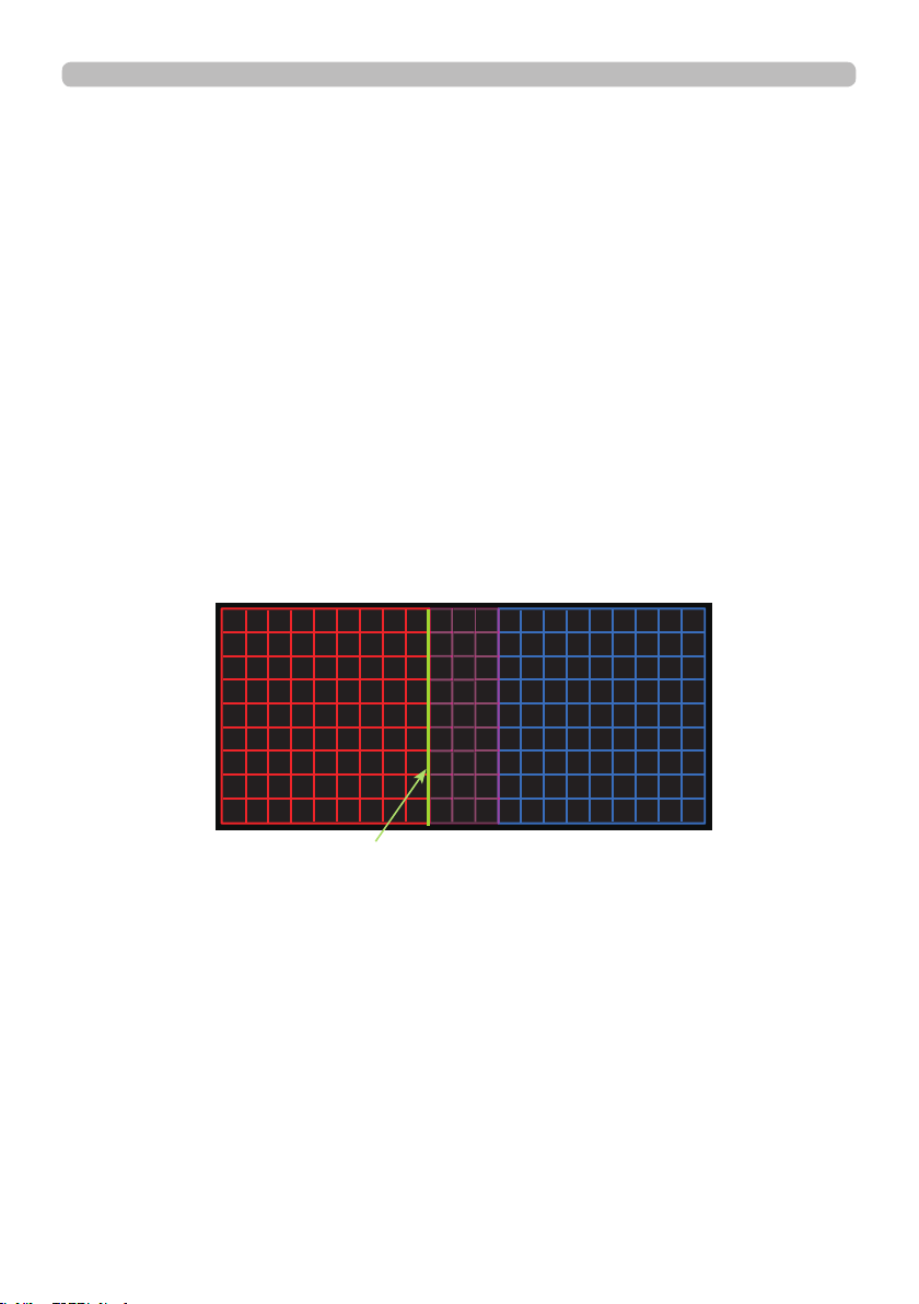
3. BLENDING REGION
3.1 Specifying Blending Region
Blending Region can be speci ed for left and right sides with
◄/► buttons
and
for top and bottom sides with ▲/▼
buttons
.
Specify Blending Region for each projector.
Adjust them referring to the guide displayed during the adjustment of Blending
Region.
* 20% of resolution is recommended for blending region.
(continued on next page)
Guide line

35
Ope rating
(continued on next page)
4.1 Displaying Cropping Menu
Select CROPPING with ▲/▼ buttons and press
►
, ENTER button to display
Cropping Menu.
4.2 Setting Cropping
Select MODE with ▲/▼ buttons and select ON with
◄/► buttons
.
Input image is automatically cut out according to the settings of Blending
Region.
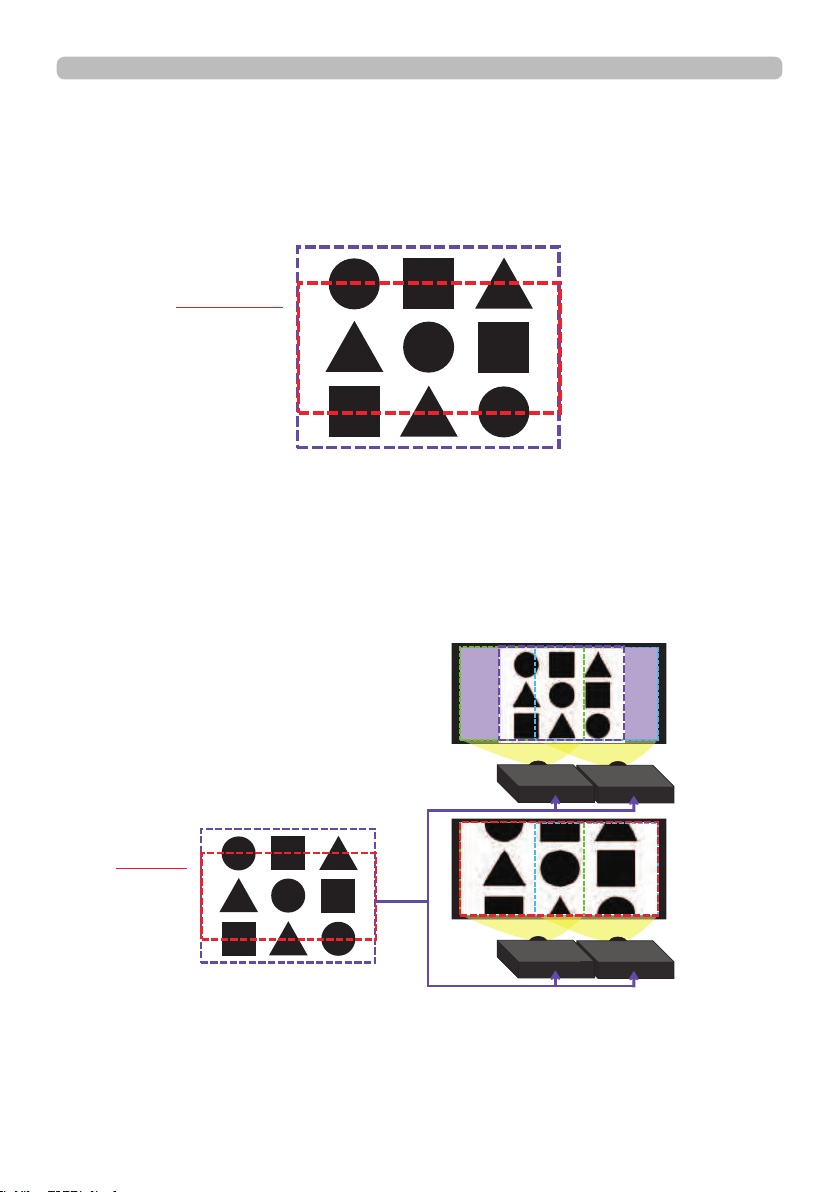
4. CROPPING
When inputting the same image to each projector, Cropping function enables
projector to cut out a part of input image and display one image on a large
screen. The following patterns are supported.
1 x 2
2 x 2
2 x 1
36
Ope rating
4.3 Adjusting Cropping Area
Adjust Cropping Area when cutting out a part of input image.
Press ENTER button and then press
◄ button
to select SETUP, and MODE
switches to ON automatically.
(continued on next page)
4.4 Adjusting Cropping Area of the other projector.
Set Cropping Area of the other projector with the same value as one projector.
Input image is automatically cut out according to the settings of Blending
Region.
* When you want to keep input image from not being seen while setting up, set
BLANK to ON.
Input Image
Cropping
Input Image
Cropping

37
Ope rating
5. DIMMING LEVEL
Adjusts the brightness of the projectors which are using Blending.
Using the ◄/► buttons to adjust the dimming level.
6. WHITE BALANCE
Adjusts the white balance of the whole screen.
6.1 OFFSET
OFFSET adjustments change the color intensity on the whole tones.
6.2 GAIN
GAIN adjustments mainly affect color intensity on the brighter tones.
7. BLACK LEVEL
Adjusts black color level of the projectors which are using Blending.
Adjusts the adjustment value of R/G/B at the same time when W is selected.
When each of R/G/B is selected, the adjustment value of R/G/B can be
adjusted respectively.
• The positional deviation of the screen may occur after installing
the projector over time. In that case, perform the screen adjustment again to
correct the positional deviation.
NOT E
38
Ope rating
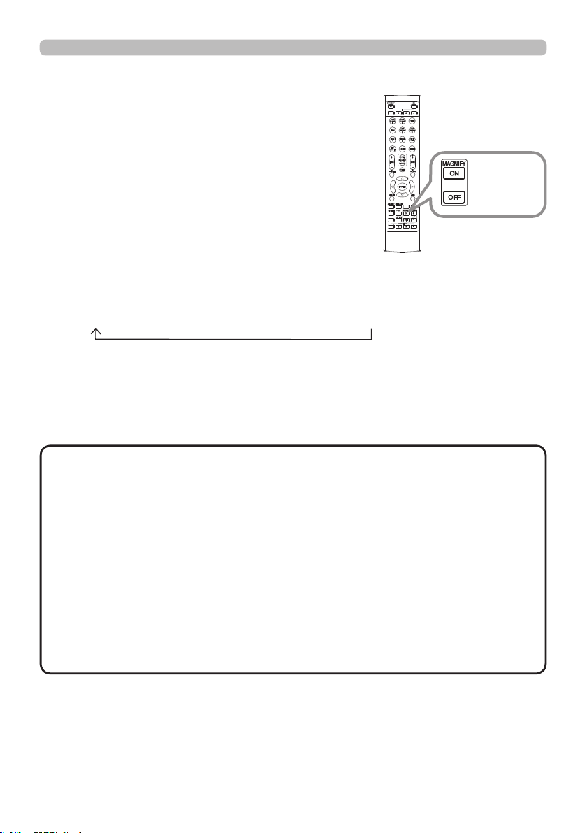
1.
Using t he m a gnify feat ure
2.
3.
4.
Press the MAGNIFY ON button on the remote
control.
The picture will be magnied, and the MAGNIFY
dialog will appear on the screen. When the
MAGNIFY ON button is pressed for the rst time
after the projector is turned on, the picture will
be zoomed by 1.5 times. On the dialog, triangle
marks to show each direction will be displayed.
The display magnication of the projector switches in order with every press
of the MAGNIFY ON button.
1.5 times 2 times 3 times 4 times 1 time
While the triangles are displayed on the dialog, use the ▲/▼/◄/► cursor
buttons to shift the magnifying area.
Press the MAGNIFY OFF button on the remote control to exit magnication.
• The MAGNIFY dialog will automatically disappear in several seconds
with no operation. The dialog will appear again if the MAGNIFY ON button is
pressed when the dialog has automatically disappeared.
• The magnication is automatically disabled when the displaying signal or its
display condition is changed.
• While the magnication is active, the keystone distortion condition may vary.
It will be restored when the magnication is disabled.
• Some horizontal stripes might be visible on the image while magnication is
active.
• This function is not available in the following cases:
- A sync signal in the range not supported is input.
- There is no input signal.
- EDGE BLENDING is set to ON.
NOT E
INFO
NETWORK
INTERACTIVE
MAGNIFY
ON/OFF
button
39
Ope rating
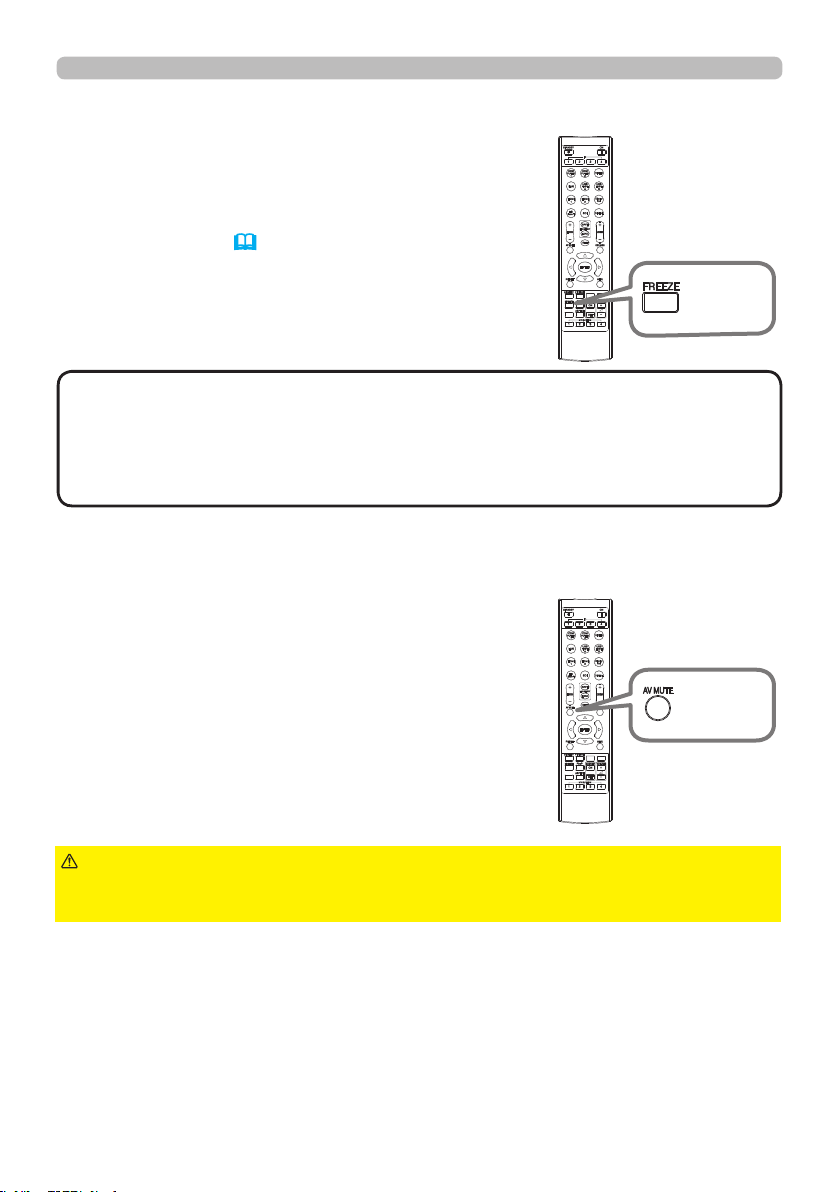
Press the FREEZE button on the remote control.
The “FREEZE” indication will appear on the screen
(however, the indication will not appear when
SILENT or INHIBIT is selected for the OSD MESSAGE
item in the SETUP (56)), and the projector will go
into the FREEZE mode, which the picture is frozen.
To exit the FREEZE mode and restore the screen to
normal, press the FREEZE button again.
Te mpora rily free zing the scre en
• The projector automatically exits from the FREEZE mode when some
control buttons are pressed.
• Do not leave the projector in the FREEZE mode for too long.
• Images might appear degraded when this function is operated, but it is not a
malfunction.
NOT E
Press AV MUTE button on the remote control.
The BLANK screen will be displayed instead of
the screen of input signal.
To exit from the BLANK screen and return to the
input signal screen, press AV MUTE button again.
Te mpora rily bla nking t he scre en
►If you wish to have a blank screen while the light source is lit,
use the BLANK function above.
Taking any other action may cause the damage on the projector.
CAUT I ON
INFO
NETWORK
INTERACTIVE
INFO
NETWORK
INTERACTIVE
FREEZE
button
AV MUTE
button

40
Ope rating
INFO
NETWORK
INTERACTIVE
The PbyP / PinP is a function for displaying two different picture signals on a
screen that is separated into main and sub areas for each signal.
PbyP (Pic ture by Pic ture ) / PinP (Pic ture in Pic ture)
•
There are certain functions that cannot be used when in the PbyP /
PinP mode.
• A message will be displayed when buttons that cannot be used are pressed
(70). However, note that there are certain unusable buttons for which
messages are not displayed.
• The functions on the OSD menu that cannot be used are displayed in gray
and cannot be selected.
NOT E
(continued on next page)
Press the PbyP button on the remote control. This activates
the PbyP / PinP mode.
The screen displayed before the
PbyP button was pressed will be displayed as the main
area. Most of operations are effective for the main area
only. To quit the PbyP / PinP mode, press the PbyP button
again.
PbyP
button

41
Ope rating
PbyP (Picture by Picture) / PinP (Picture in Picture) (continued)
The setting information will be appeared for several seconds when the PbyP /
PinP function is started. Displays the input information for each area. A frame
around the main area will be displayed.
Setting information
(continued on next page)
42
Ope rating
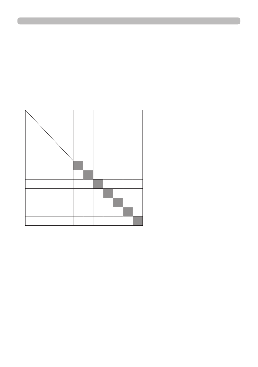
Press any button to select an input port on the remote control or press the
INPUT button on the control panel. A dialog box to select the input signal for
the main area will be displayed. Choose a signal using the ▲/▼ buttons. To
change the signal in the sub area, switch temporarily across to the main area
with the ◄/► buttons.
Displaying the same signal on the both areas is not allowed. Refer to the table
for details on available input signal combinations. Any combinations marked
with "X" cannot be selected.
Changing the picture input signal
Sub area
Main area
HDMI 1
HDMI 2
COMPUTER IN 1
COMPUTER IN 2
HDBaseT
SDI
DVI-D
HDMI 1
O O O X O X
HDMI 2
O X X O X O
COMPUTER IN 1
O X X O X O
COMPUTER IN 2
O X X O X O
HDBaseT
X O O O O X
SDI
O X X X O O
DVI-D
X O O O X O
PbyP (Picture by Picture) / PinP(Picture in Picture) (continued)
(continued on next page)

43
Ope rating
Select in the INPUT MENU > PinP POSITION (53).
Changing the position of sub area
PbyP (Picture by Picture) / PinP (Picture in Picture) (continued)
• For some signals, it may not be displayed correctly in the PbyP / PinP
mode, even if it can be displayed properly in the normal mode.
• PbyP/PinP is unavailable when ON is selected in GEOMETRY CORRECTION
> EDGE BLENDING > MODE.
• PbyP / PinP is unavailable when 3D is enabled.
NOT E
Press the MY BUTTON assigned the PbyP / PinP SWAP (
59). The position of
the both area is exchanged without any setting change.
PbyP / PinP SWAP function
44
Ope rating
INFO
NETWORK
INTERACTIVE
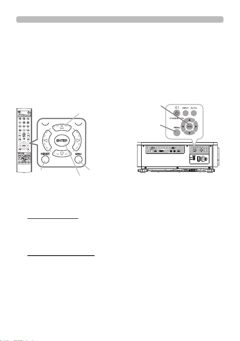
1.
To start the MENU, press the MENU button. The MENU you last used (EASY
or ADVANCED) will appear. EASY MENU has priority to appear just after
powered on.
Using t he m enu function
2.
(1) Use the ▲/▼ cursor buttons to select an item to operate. If you want to
change it to the ADVANCED MENU, select the ADVANCED MENU.
(2) Use the ◄/► cursor buttons to operate the item.
This projector has the following menus:
PICTURE, IMAGE, INPUT, SETUP, SCREEN, OPTION, NETWORK, and EASY
MENU. EASY MENU consists of functions often used, and the other menus are
classied into each purpose and brought together as the ADVANCED MENU.
Each of these menus is operated using the same methods. While the projector
is displaying any menu, the MENU button on the projector works as the cursor
buttons. The basic operations of these menus are as follows.
Some items cannot be operated depending on the selected channel or input
signal. Items that cannot be operated are displayed in light gray.
In the EASY MENU
(continued on next page)
(1) Use the ▲/▼ cursor buttons to select a menu.
If you want to change it to the EASY MENU, select the EASY MENU. The
items in the menu appear on the right side.
(2) Press the ► cursor button or ENTER button to move the cursor to the
right side. Then use the ▲/▼ cursor buttons to select an item to operate
and press the ► cursor button or ENTER button to progress. The
operation menu or dialog of the selected item will appear.
(3) Use the buttons as instructed in the OSD to operate the item.
In the ADVANCED MENU
ENTER button
MENU button
ENTER button
RESET button
Cursor buttons
LAN
IN OUT
SDI
COMPUTER IN 2
REMOTE
CONTROL HDBaseT HDMI 1 DVI-D HDMI 2
CONTROL V H
B/Cb/Pb
G/Y R/Cr/Pr COMPUTER IN 1
EXITMENU
LENS
SHIFT
INPUT ASPECT BLANK
LENS
CENTERING
AUTO
FOCUS ZOOM
12V OUTPUT
(OPTION)
MENU button

45
Ope rating
Using the menu function (continued)
3.
To close the MENU, press the MENU button again or select EXIT and press
the ◄ cursor button or ENTER button. Even if you do not do anything, the
dialog will automatically disappear after about 30 seconds.
Indic ation in OSD (On Scre e n Display)
The meanings of the general words on the OSD are as follows.
Indication Meaning
EXIT
Selecting this word nishes the OSD menu. It's the same as
pressing the MENU button.
RETURN Selecting this word returns the menu to the previous menu.
CANCEL or NO
Selecting this word cancels the operation in the present
menu and returns to the previous menu.
OK or YES
Selecting this word executes the prepared function or shifts
the menu to the next menu.
• Some functions cannot be performed when a certain input port is
selected, or when a certain input signal is displayed.
• When you want to reset the operation, press RESET button on the remote
control during the operation. Note that some items (ex. LANGUAGE) cannot be
reset.
• In the ADVANCED MENU, when you want to return to the previous display,
press the ◄ cursor button on the remote control.
NOT E
46
Ope rating
Using the menu function (continued)
Cont a ining ite m s of each m e nu
The items contained in the menus are as below;
Menu Items
EASY MENU (
47)
ASPECT, KEYSTONE, PERFECT FIT, PICTURE MODE,
ECO MODE, INSTALLATION, RESET, LANGUAGE,
ADVANCED MENU, EXIT
PICTURE(
48)
BRIGHTNESS, CONTRAST, COLOR, TINT, SHARPNESS,
DYNAMIC BLACK, PICTURE QUALITY, MY MEMORY
IMAGE (
52)
ASPECT, OVER SCAN, V POSITION, H POSITION, H PHASE,
H SIZE, AUTO ADJUST
INPUT (
53)
NOISE REDUCTION, COLOR SPACE, PbyP/PinP,
PinP POSITION, 3D FORMAT, 3D EYE SWAP, 3D DLP LINK
SETUP (
54)
GEOMETRY CORRECTION, ECO MODE, CUSTOM POWER,
PICTURE POSITION,
INSTALLATION, STANDBY MODE,
OSD MESSAGE
SCREEN(
57) LANGUAGE, MENU POSITION, START UP, TEMPLATE
OPTION (
58)
AUTO SEARCH, DIRECT POWER ON, AUTO POWER OFF,
MY BUTTON, SERVICE
NETWORK (
62)
NETWORK MODE, INFORMATION, SETUP,
EXTERNAL CONTROL
47
EASY M EN U
EASY MENU
Item Description
ASPECT
Switches the mode for aspect ratio.
See the ASPECT item in IMAGE menu (
52).
KEYSTONE
See the KEYSTONE item in GEOMETRY CORRECTION of SETUP
menu (
54).
PERFECT FIT
See the PERFECT FIT item in GEOMETRY CORRECTION of
SETUP menu (
54).
PICTURE MODE
Switches the picture mode.
The picture modes are combinations of GAMMA and COLOR TEMP
settings. Choose a suitable mode according to the projected source.
STANDARD
ó
NATURAL
ó
CINEMA
ó
DYNAMIC
USER-3
ó
USER-2
ó
USER-1
ó
DICOM SIM.
Refer to
(
49)
for details.
• Lines or other noise might appear on the screen when this function
is operated, but it is not a malfunction.
• DICOM SIM. is the projector's DICOM
®
("Digital Imaging and
Communication in Medicine") simulation mode. This mode
simulates the DICOM standard, which is a standard applicable to
digital communications in medicine, and can be useful for displaying
medical images, such as X-rays photos. This projector is not a
medical device and is not compliant to the DICOM standard, and
neither the projector nor the DICOM SIM. mode should be used for
medical diagnosis.
ECO MODE
Switches the ECO MODE.
See the ECO MODE item in SETUP menu (
55).
INSTALLATION
See the INSTALLATION item in SETUP menu (
55).
RESET
Performing this item resets all of the EASY MENU items except the
LANGUAGE.
A dialog is displayed for conrmation. Selecting the OK using the ►
button performs resetting.
LANGUAGE
Changes the display language.
See the LANGUAGE item in SCREEN menu (
57).
ADVANCED MENU
Press the ► or ENTER button to use the menu of PICTURE,
IMAGE, INPUT, SETUP, SCREEN, OPTION or NETWORK.
EXIT Press the ◄ or ENTER button to nish the OSD menu.

48
PICT URE m e nu
PICTURE menu
Item Description
BRIGHTNESS
Adjusts the brightness.
CONTRAST
Adjusts the contrast.
COLOR
Adjusts the strength of whole color.
TINT
Adjusts the tint.
SHARPNESS
Adjusts the sharpness.
• There may be some noise and/or the screen may icker for a
moment when an adjustment is made. This is not a malfunction.
DYNAMIC BLACK
Turn on/off the DYNAMIC BLACK function.
Use this function to congure the projector to automatically adjust
picture contrast from the source upon start up or shut down. When
activated, the projector will dynamically adjust the picture contrast
from the beginning of the projection until the content has ended.
Available while black image signal inputting.
This function might not work correctly, in the case of Analog signal
with noise.
(continued on next page)

49
PICT URE m e nu
Item Description
PICTURE
QUALITY
Selecting this item displays the PICTURE QUALITY menu.
PICTURE MODE
STANDARD
ó
NATURAL
ó
CINEMA
ó
DYNAMIC
USER-3
ó
USER-2
ó
USER-1
ó
DICOM SIM
.
STANDARD: For displaying general images
NATURAL: For displaying an image conforming to sRGB
CINEMA: For displaying cinema image
DYNAMIC: For enjoying sharp images
DICOM SIM.: For checking medical images such as X-ray photos
USER-1/2/3: For customizing
GAMMA
This feature is only available when USER-1 / USER-2 / USER-3 of
PICTURE MODE is selected.
1.0
ó
1.8
ó
2.0
ó
2.2
DICOM SIM.
ó
2.5
ó
2.35
• Lines or other noise might appear on the screen when this function
is operated, but it is not a malfunction.
(continued on next page)

50
PICT URE m e nu
Item Description
PICTURE
QUALITY
(continued)
COLOR TEMP
This feature is only available when USER-1 / USER-2 / USER-3 of
PICTURE MODE is selected.
5400K
ó
CUSTOM-1
ó
6500K
ó
CUSTOM-2
CUSTOM-5 7500K
NATIVE
ó
CUSTOM-4
ó
9300K
ó
CUSTOM-3
Selecting a mode whose name includes CUSTOM and then pressing
the ► button or the ENTER button displays a dialog to aid you in
adjusting the OFFSET and GAIN of the selected mode.
OFFSET adjustments change the color intensity on the whole tones.
GAIN adjustments mainly affect color intensity on the brighter tones.
• Lines or other noise might appear on the screen when this function
is operated, but it is not a malfunction.
(continued on next page)

51
PICT URE m e nu
Item Description
PICTURE
QUALITY
(continued)
ACCENTUALIZER
ACCENTUALIZER is a function to improve the legibility.
Using the ◄/► buttons adjusts the sharpness.
Weak
ó
Strong
• There may be some noise and/or the screen may icker for a
moment when an adjustment is made. This is not a malfunction.
HDCR
A function to show a clear picture in a bright room.
Using the◄/► buttons adjusts the contrast.
COLOR MANAGEMENT
A function to adjust color HUE, SATURATION, and LUMINANCE
respectively for red, yellow, green, cyan, blue, and magenta.
MY MEMORY
This projector has 4 memories for adjustment data (for all the items
of the PICTURE menu).
LOAD-1, LOAD-2, LOAD-3, LOAD-4
Performing a LOAD function loads the data from the memory linked
in the number included in the function’s name, and adjusts the
picture automatically depending on the data.
• The LOAD functions whose linked memory has no data are
skipped.
• Remember that the current adjusted condition will be lost by
loading data. If you want to keep the current adjustment, save it
before performing a LOAD function.
• There may be some noise and the screen may icker for a
moment when loading data. This is not malfunction.
• You can perform the LOAD function using MY BUTTON. See MY
BUTTON item in OPTION menu (
59).
SAVE-1, SAVE-2, SAVE-3, SAVE-4
Performing a SAVE function saves the current adjustment data into
the memory linked in the number included in the function’s name.
• Remember that the current data being stored of a memory will be
lost by saving new data into the memory.

52
IM AGE me nu
IMAGE menu
Item Description
ASPECT
Switches the mode for aspect ratio.
NORMAL
ó
4:3
ó
16:9
ó
16:10
ó
ZOOM
ó
NATIVE
If there is no signal
16:10 (xed)
• The NORMAL mode keeps the original aspect ratio of the signal.
OVER SCAN
Switches the OVER SCAN mode.
OFF: Unmagnied display
CROP: Reduced display
ZOOM: Magnied display
V POSITION
Adjusts the vertical position.
• Over-adjusting the vertical position may cause noise to appear on
the screen. If this occurs, reset the vertical position to the default
setting. Pressing the RESET button when the V POSITION is
selected will reset the V POSITION to the default setting.
H POSITION
Adjusts the horizontal position.
•
Over-adjusting the horizontal position may cause noise to appear on
the screen. If this occurs, reset the horizontal position to the default
setting. Pressing the RESET button when the H POSITION is selected
will reset the H POSITION to the default setting.
H PHASE
Adjusts the horizontal phase to eliminate icker.
H SIZE
Adjusts the horizontal size.
• When this adjustment is excessive, the picture may not be
displayed correctly. In such a case, reset the adjustment by pressing
the RESET button on the remote control during this operation.
• Images might appear degraded when this function is operated, but
it is not a malfunction.
AUTO ADJUST Adjusts the signal synchronization automatically.

53
IN PU T m e nu
INPUT menu
Item Description
NOISE
REDUCTION
Adjusts the noise reduction level.
HIGH
ó
LOW
COLOR SPACE
Switches the mode for color space.
AUTO
ó
REC709
ó
REC601
ó
RGB PC
ó
RGB VIDEO
PbyP / PinP
Switches on/off of PbyP/PinP.
This function is unavailable when EDGE BLENDING is set to ON or
3D display is enabled.
PinP POSITION
Changes the position of sub area in PinP mode.
This function is unavailable when PbyP / PinP is set to OFF.
3D FORMAT
AUTO is selected as the default setting.
If 3D image is not displayed,
it means the input signal does not contain 3D detection signal or
it cannot be detected by the projector. In that case, you need to
select the appropriate 3D format manually. You can select OFF /
AUTO / SIDE BY SIDE (HALF) / TOP AND BOTTOM / FRAME
SEQUENTIAL.
3D EYE SWAP
Select "NORMAL" or "REVERSE" to display the appropriate picture.
This function is unavailable when 3D FORMAT is set to OFF or
AUTO.
3D DLP LINK
This projector supports DLP Link glasses only. If your 3D glasses
are not DLP Link format, set this function to "OFF".
This function is unavailable when 3D FORMAT is set to OFF or
AUTO.
54
SET U P m e nu
SETUP menu
Item Description
GEOMETRY
CORRECTION
KEYSTONE
Selecting this item displays the KEYSTONE dialog.
For details, see KEYSTONE in Correcting the distortion(
31
).
• When the zoom adjustment is set to the TELE (telephoto focus),
this function may be excessive. This function should be used when
the zoom adjustment is set to the full WIDE (wide-angle focus)
whenever possible.
• When the horizontal lens shift is not set to the center, this function
may not work well.
•
This function is unavailable when the screen is activated by
PERFECT FIT (
32
), and WARPING (
33
)
.
PERFECT FIT
Selecting this item displays the PERFECT FIT dialog. For details,
see PERFECT FIT in Correcting the distortion (
32
).
•
This function is unavailable when the screen is activated by
KEYSTONE (
31
), and WARPING (
33
)
.
WARPING
Selecting this item displays the WARPING dialog. For details, see
Application Manual of this feature.
• This function is unavailable when the screen is activated by
KEYSTONE
(
31
)
and PERFECT FIT
(
32
)
.
EDGE BLENDING
Selecting this item displays the EDGE BLENDING dialog. For
details, see EDGE BLENDING feature (
34
~
37
).
PATTERN
Select PATTERN with ▲/▼ buttons.
Displayed pattern [Off/1/2/3/4/5/6] can be switched with ◄/► buttons.
PATTERN 1: Frame
PATTERN 2: Red Grid
PATTERN 3: Green Grid
PATTERN 4: Blue Grid
PATTERN 5: Vertical 9 steps
PATTERN 6: Horizontal 9 steps
OFF: Displays the input signal.
(continued on next page)
55
SET U P m e nu
Item Description
ECO MODE
Switches the Eco mode.
NORMAL
ó
ECO
ó
CUSTOM
• When the item other than NORMAL is selected, acoustic noise and
screen brightness are reduced.
CUSTOM POWER
Adjusts the brightness of the light source when ECO MODE is set
to CUSTOM. This function is unavailable when ECO MODE is set to
other than CUSTOM.
PICTURE
POSITION
Using the ▲/▼/◄/► cursor buttons selects the desirable picture
position.
The PICTURE POSITION is not changed if any of the following
cases apply.
・
There is no non-display area (black display or background display)
or it is not displayed on the screen.
• One of the following messages is displayed on the screen:
"NO INPUT IS DETECTED"
"SYNC IS OUT OF RANGE"
"INVALID SCAN FREQ."
• The BLANK or TEMPLATE function is selected.
INSTALLATION
FRONT / DESKTOP
REAR / DESKTOP
REAR / CEILING
FRONT / CEILING
• When REAR / CEILING or FRONT / CEILING is selected,
functions of ▲/▼/◄/► cursor buttons on the projector are reversed
after the dialog menu disappears.
(continued on next page)

56
SET U P m e nu
Item Description
STANDBY MODE
Switches the standby mode setting.
NORMAL
ó
SAVING
• When SAVING is selected, the RS-232C communication control
except to turn the projector on and the network function are disabled
while the projector is in the standby mode.
• When SAVING is selected, the CENTERING feature while the
projector is in the standby mode is disabled.
• When SAVING is selected, the HDBaseT functions are disabled
while the projector is in the standby mode.
OSD MESSAGE
Switches how to display the OSD messages.
■NORMAL
: All message functions work.
■SILENT
: The following message functions do not work.
“AUTO IN PROGRESS” while automatically adjusting.
“NO INPUT IS DETECTED”
“SYNC IS OUT OF RANGE”
“INVALID SCAN FREQ.”
“NOT AVAILABLE”
“Searching….” while searching for the input.
“Detecting….” while an input signal is detected.
The indication of the ZOOM displayed by changing.
*While operating from the remote control only.
The indication of the FOCUS displayed by changing.
The indication of the input signal displayed by changing.
The indication of the aspect ratio displayed by changing.
The indication of the PICTURE MODE displayed by changing.
The indication of the MY MEMORY displayed by changing.
The indication of “FREEZE” and “II” while freezing the screen by
pressing the FREEZE button.
The indication of the TEMPLATE displayed by changing.
The indication of the ECO MODE displayed by changing.
■INHIBIT
: All message functions do not work.
The only buttons will function are as below.
STANDBY, ON
• To change this function, follow the steps below.
1. Press the OSD MSG button on the remote control for 3 sec.
2. The INHIBIT OSD will be displayed.
While this OSD is displayed, press the OSD MSG button again
on the remote control.
3. Toggle and change the function.
NORMAL
ó
SILENT
ó
INHIBIT
57
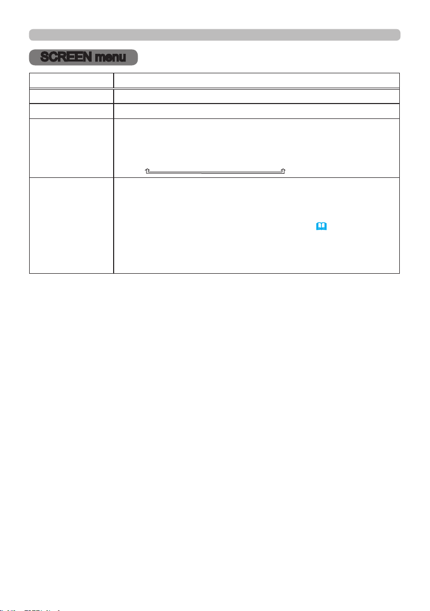
SCREEN me nu
SCREEN menu
Item Description
LANGUAGE
Switches the OSD (On Screen Display) language.
MENU POSITION Switches the menu position.
START UP
Switches the mode for the start-up screen.
The start-up screen is a screen displayed when no signal or an
unsuitable signal is detected.
ORIGINAL
ó
BLACK
ó
BLUE
ó
WHITE
TEMPLATE
Press the ► cursor (or the ENTER) button to display the selected
template, and press the ◄ cursor button to close the displayed
screen.
The last selected template is displayed when the MY BUTTON
allocated to the TEMPLATE function is pressed (
59).
TEST PATTERN
ó
DOT-LINE1
ó
DOT-LINE2
ó
DOT-LINE3
STACK
ó
MAP2
ó
MAP1
ó
CIRCLE2
ó
CIRCLE1
ó
DOT-LINE4
58
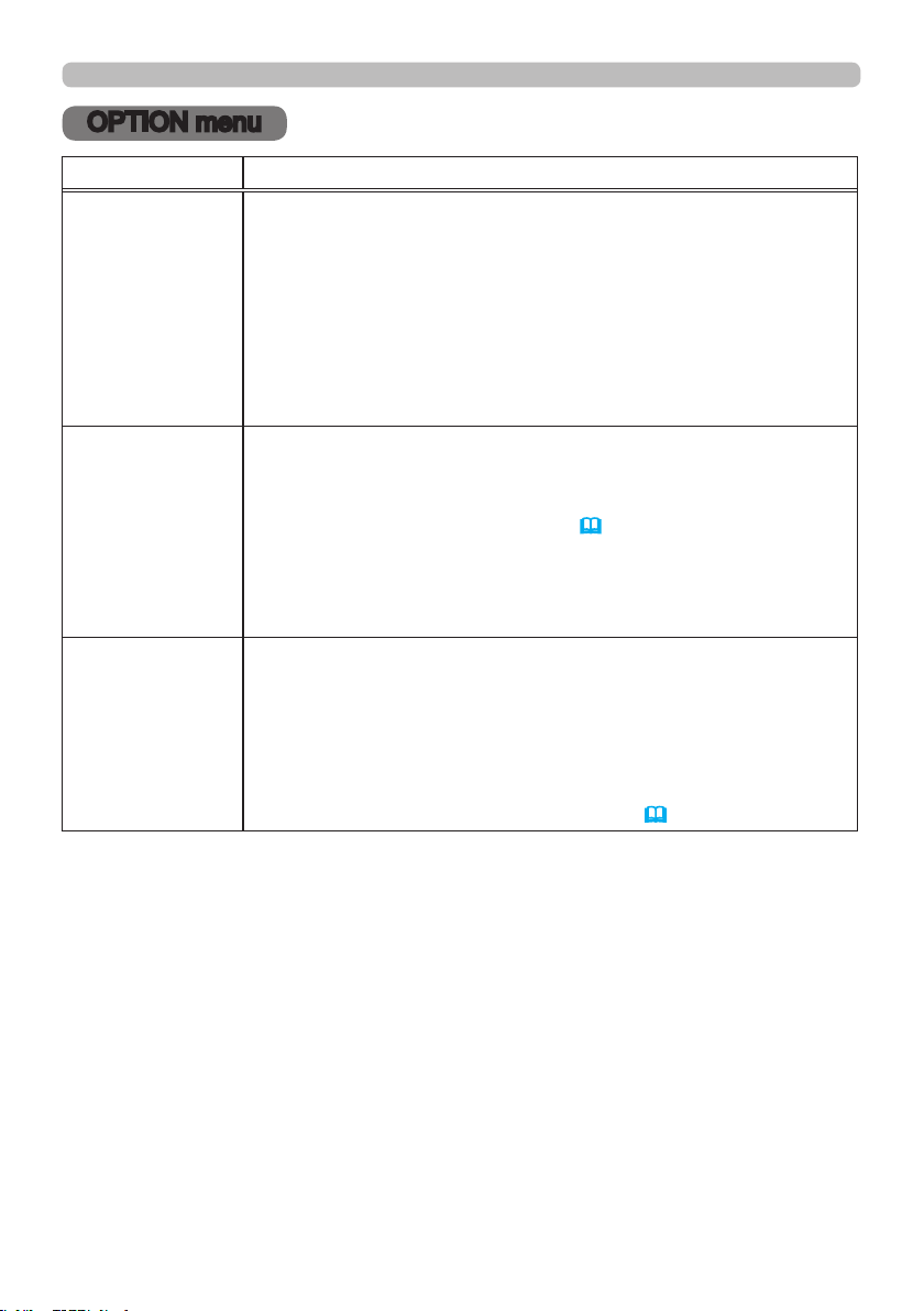
OPT I ON m e nu
OPTION menu
Item Description
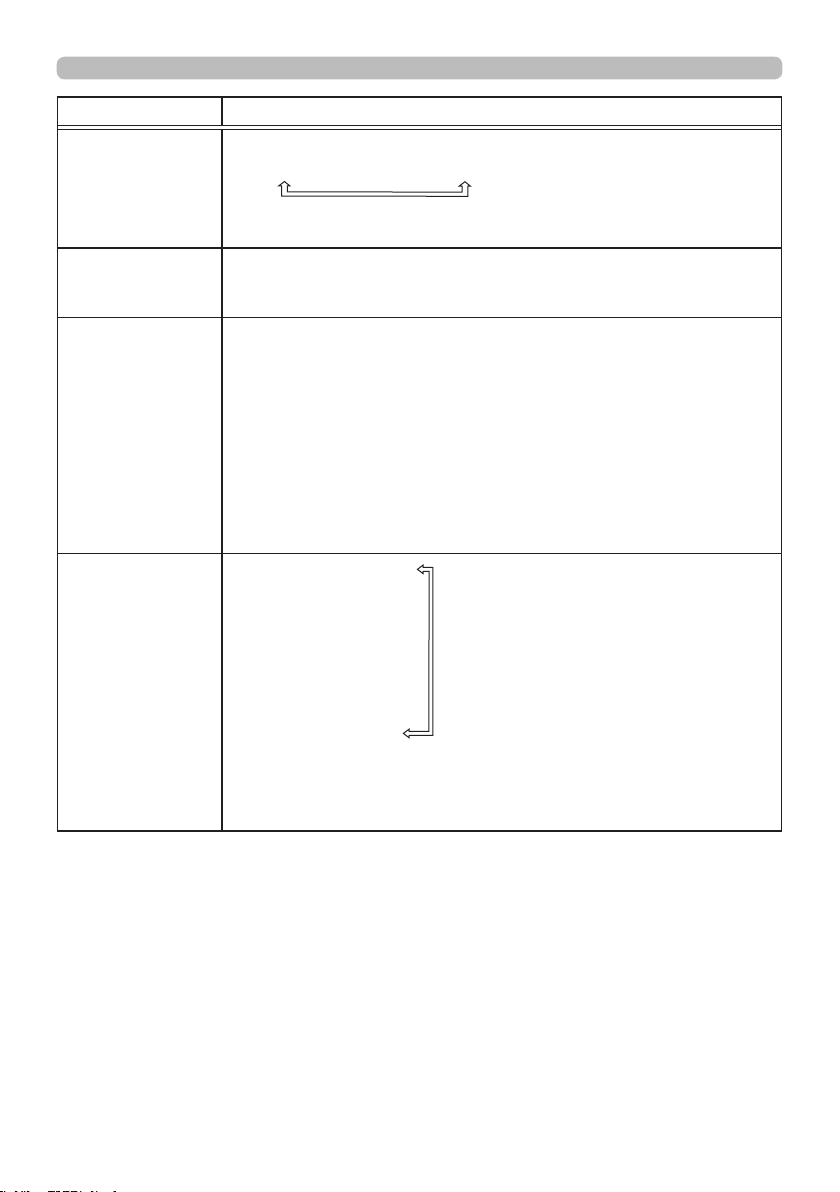
AUTO SEARCH
Turns on/off the automatic signal search function.
ON
ó
OFF
When the ON is selected, detecting no signal automatically cycles
through input ports in the following order. The search is started from
the current port. Then when an input is found, the projector will stop
searching and display the image.
HDMI 1
HDMI 2
COMPUTER IN1
DVI-D
ï
SDI
ï
HDBaseT
ï
COMPUTER IN2
DIRECT POWER
ON
Turns on/off the DIRECT POWER ON function.
ON
ó
OFF
When set to the ON, the light source in projector will be automatically
turned on without the usual procedure (
24), only when the projector
is supplied with the power after the power was cut while the light source
was on.
• This function does not work as long as the power has been
supplied to the projector while the light source is off.
AUTO POWER
OFF
Turns on/off the function to turn off the projector automatically in 20
minutes when no signal or sync out.
ON
ó
OFF
If one of the projector's buttons or the remote control buttons
is pressed or one of the commands (except get commands) is
transmitted to the CONTROL port during the corresponding time,
projector will not be turned off.
Refer to the section Turning off the power (
24).
(continued on next page)
59
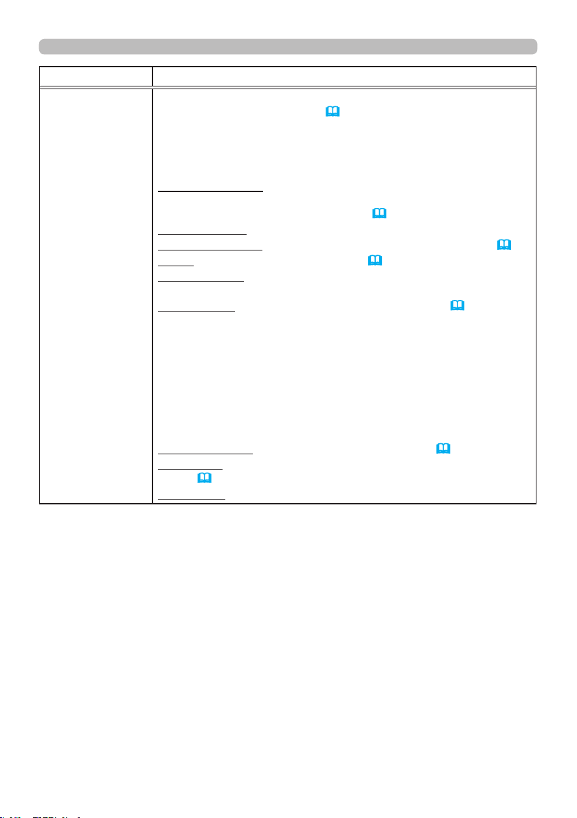
OPT I ON m e nu
Item Description
MY BUTTON
This item is to assign one of the following functions to MY BUTTON
(1 to 4) on the remote control (
7).
(1) Select a button from MY BUTTON - 1 to 4 and press the ► or
ENTER button to display the MY BUTTON setup dialog.
(2) Set one of the following functions to the chosen button. Press
the ENTER button to save the setting.
PbyP / PinP SWAP: Swaps the picture on the right with one on
the left in the PbyP mode. Swaps the primary picture and the
secondary picture in the PinP mode. (
43)
PinP POSITION: Toggles the PinP position.
ACCENTUALIZER: Turns on/off the ACCENTUALIZER dialog
(
51).
HDCR: Turns on/off the HDCR dialog
(
51).
INFORMATION: Displays SERVICE_ INFORMATION, NETWORK_
INFORMATION, or nothing.
MY MEMORY: Loads one of adjustment data stored (
51).
When more than one data are saved, the adjustment changes
every time the MY BUTTON is pressed.
When no data is saved in memory, the dialog "No saved data"
appears.
When the current adjustment is not saved to memory, the dialog
appears.
If you want to keep the current adjustment, press the ► button to
exit. Otherwise loading a data will overwrite the current adjusted
condition.
PICTURE MODE: Changes the PICTURE MODE (
49).
TEMPLATE: Makes the template pattern selected to the TEMPLATE
item (
57) appear or disappear.
ECO MODE: Changes the ECO MODE.
(continued on next page)

60
OPT I ON m e nu
Item Description
SERVICE
ALTITUDE
Switches the rotation speed of the cooling fans. It is recommended
to leave it at AUTO.
AUTO: The projector changes the rotation speed automatically to
suit the altitude and other environmental factors. Choose an
option below when there is a trouble with the AUTO mode.
NORMAL-1: This mode can be used below 610m (2000ft.).
NORMAL-2: This mode can be used below 1219m (4000ft.).
HIGH-1: This mode can be used between 1219 to 1676m (4000 to
5500ft.).
HIGH-2: This mode can be used between 1676 to 3048m (5500 to
10000ft.).
HIGH-3: This mode can be used between 3048 to 4200m (10000 to
13780ft.).
LENS TYPE
(1) Select the current lens type and press the ► or ENTER button.
If AUTO is selected, the projector determines the lens type
automatically.
(2) A message dialog is displayed for conrmation. Press the ► or
ENTER button to save the lens type.
• This setting has an inuence on the keystone distortion etc.
• The lens type determined by the projector will be displayed on the
right of "AUTO".
• If the projector cannot determine the lens type automatically when
this item is set to AUTO, "UNKNOWN LENS" is displayed on the
right of "AUTO".
• About the optional lens, ask your dealer.
(continued on next page)

61
OPT I ON m e nu
Item Description
SERVICE
(continued)
INFRARED REMOTE
Turns on/off the Infrared sensor. Wired remote operates regardless
of this item.
REMOTE ID
Select ID and press the ► button.
ALL
ó
1
ó
2
ó
3
ó
4
The projector is controlled by the remote control whose ID button
is set the same number as this number. When the ALL is selected,
the projector is controlled by a remote control irrespective of the ID
setting.
INFORMATION
Selecting this item displays a dialog titled “SERVICE_INFORMATION”.
It shows the information about the current input.
• This item cannot be selected for no signal and sync out.
FACTORY RESET
Selecting OK using the ► button performs this function. By this
function, all the items in all of menus will collectively return to the
initial setting. Note that the items LASER TIME, LANGUAGE,
STANDBY MODE, and NETWORK settings are not reset.
CANCEL
OK
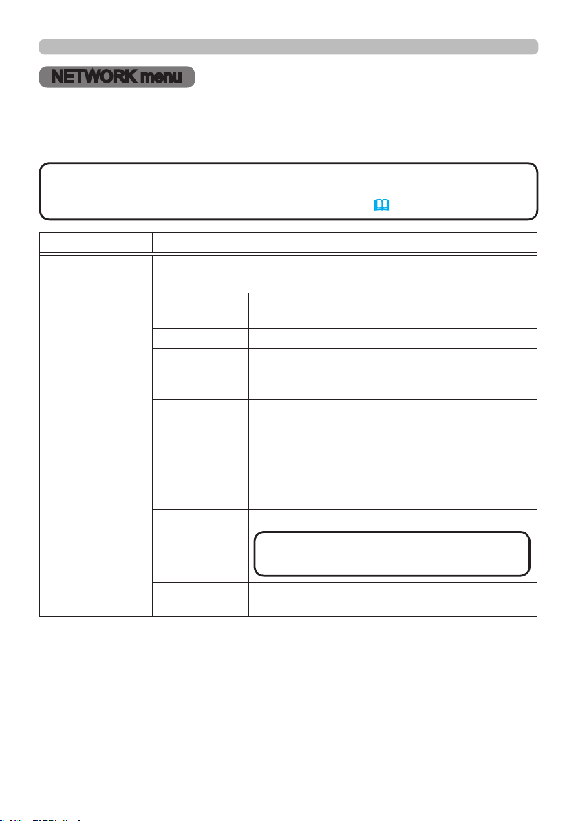
62
NETWORK m e nu
NETWORK menu
Remember that incorrect network settings on this projector may cause trouble on
the network. Be sure to consult with your network administrator before connecting
to an existing access point on your network.
• The network function is not available when STANDBY MODE is set
to SAVING and the projector is in standby mode. Connect the projector to the
network after setting STANDBY MODE to NORMAL. (56)
NOT E
Item Description
NETWORK MODE
Switches NETWORK MODE. Select USER.
USER
ó
SERVICE
INFORMATION
NETWORK
MODE
Displays USER or SERVICE of NETWORK MODE.
DHCP Displays the DHCP setting.
IP ADDRESS
Displays the IP address.
This function can only be used when DHCP is set
to OFF.
SUBNET
MASK
Displays the subnet mask.
This function can only be used when DHCP is set
to OFF.
DEFAULT
GATEWAY
Displays the default gateway.
This function can only be used when DHCP is set
to OFF.
DNS SERVER
Displays the DNS server address.
MAC
ADDRESS
Displays the MAC address.
(continued on next page)
• This setting cannot be obtained
automatically.
NOT E
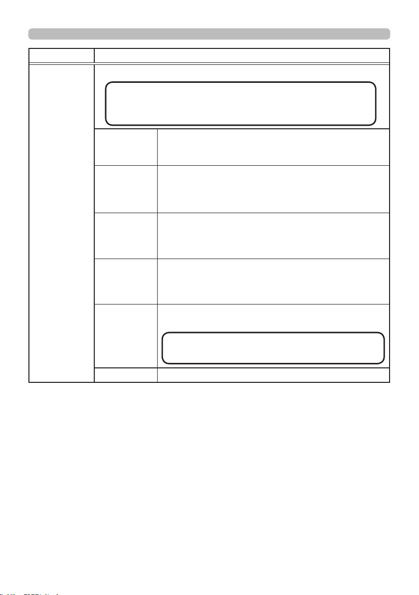
63
NETWORK m e nu
Item Description
SETUP
Congures wired network.
DHCP
Switches on/off of DHCP.
When DHCP is on, an IP address is obtained
automatically.
IP ADDRESS
Congures the IP address when DHCP is disabled.
Enter the IP ADDRESS.
This function can only be used when DHCP is set to
OFF.
SUBNET
MASK
Congures the subnet mask when DHCP is disabled.
Enter the SUBNET MASK.
This function can only be used when DHCP is set to
OFF.
DEFAULT
GATEWAY
Congures the default gateway when DHCP is disabled.
Enter the DEFAULT GATEWAY address.
This function can only be used when DHCP is set to
OFF.
DNS
SERVER
Congures the DNS server address.
Enter the DNS server address.
APPLY Saves the network settings above.
(continued on next page)
・ Setting values are not saved if Menu disappears
before selecting APPLY.
・ Execute APPLY after changing the settings.
NOT E
・ This setting cannot be obtained automatically.
NOT E

64
NETWORK m e nu
Item Description
EXTERNAL
CONTROL
AMX D.D.
(AMX Device
Discovery)
Turns on/off the AMX Device Discovery.
ON
ó
OFF
When ON is selected, the projector can be detected
by controllers of AMX connected to the same network.
For the details of AMX Device Discovery, visit the AMX
web site.
URL: http://www.amx.com/
CRESTRON
Turns on/off the Crestron Connected
TM
.
ON
ó
OFF
When ON is selected, controlling and managing the
projector can be performed by using the controllers
of Crestron connected to the same network. For the
details of Crestron Connected
TM
, visit the following web
site.
URL: http://www.crestron.com/
EXTRON
Turns on/off the Extron.
ON
ó
OFF
When ON is selected, the controllers of Extron
connected using HDBaseT
TM
can detect the projector.
For the details of Extron, visit the following web site.
URL: http://www.extron.com/

65
We b Cont rol
You can adjust or control the projector via a network from a web browser on a
computer connected to the same network.
■Projector Web Control
You can control the projector, collect the status such as laser time, and set
e-mail or schedule, etc. in Projector Web Control.
Recommended web browser
・ Internet Explorer
®
9/ 10/ 11
• Web browsers other than recommended ones may not work.
• If JavaScript
®
is disabled in your web browser conguration, you must enable
JavaScript
®
in order to use the projector web pages properly. See the Help les
for your web browser for details on how to enable JavaScript
®
.
• It is recommended that all web browser updates are installed.
• If data is transferred via wireless and wired LAN at the same time, the
projector may not process the data correctly.
NOT E
(continued on next page)
■Crestron e-Control
Crestron e-Control
®
is a control interface using a web browser provided by
Crestron Electronics, Inc..
Crestron e-Control
®
can control and monitor the projector.
Web Control
66
We b Cont rol
• Crestron e-Control
®
is created using Flash
®
. You need to install
Adobe
®
Flash
®
Player on your computer to use Crestron e-Control
®
. Crestron
e-Control
®
is not displayed in a web browser that does not support Flash
®
.
• If Crestron e-Control
®
in the Network Settings (64) is set to Disable,
Crestron e-Control
®
cannot be used to operate the projector.
NOT E
Refer to the following for conguring or controlling the projector via a web browser.
Make sure that your computer and the projector is connected via network, and
then start Web browser.
Enter the projector's IP address into URL input box of the Web browser as the
example below, and then press the Enter key or
button.
Example: If the IP address of the projector is set to 192.168.1.10:
Enter “http://192.168.1.10/” into the address bar of the web browser
and press the Enter key or click
button.
If a correct URL is input, and the projector and your computer are connected to
the same network correctly, the selection window will be displayed.
• Do not control the projector with the projector's menu or remote
control, and via Web Control at the same time. It may cause some operational
errors in the projector.
• The language used on the Projector Web Control is the same as that of the
OSD on the projector. If you want to change it, you need to change the OSD
language on the projector. (57)
NOT E
Login (Project or Web Control)
To use the Projector Web Control function, you need to login with your user name
and password.
Below are the factory default settings for user name and password.
User name Administrator
Password <blank>

67
Ma inte nanc e
►Before taking care of the ventilation inlet, make sure the
power cable is not plugged in, then allow the projector to cool sufciently. Before
taking care of the ventilation inlet, make sure to turn the projector off and to pull
out the power cable, then allow the inside of the projector to cool sufciently.
If you take care of the projector with the power cord connected, it could cause
a re or an electrical shock. If you handle the projector in a high temperature
state, it could cause a burn.
WARN I N G
Maintenance
If you nd something abnormal with the light source, contact your dealer or
service company.
Clea ning the ve ntilat ion inle t
It is recommended to check and clean the ventilation inlet periodically for
maintaining the ventilation inside of the projector and normal operation.
If a message prompts you to clean or check the ventilation inlet, or if the TEMP.
indicator lights in red, clean the ventilation inlet immediately.
1.
Turn the projector off and unplug the power cord. Allow the projector to cool
down sufciently.
2.
Use a vacuum cleaner on and around the ventilation inlet.
How to clean the ventilation inlet

68
Ma inte nanc e
In order to ensure the safe use of your projector, have it cleaned and inspected by
your dealer about once every year.
1.
Turn the projector off, and unplug the power cord. Allow the projector to cool
sufciently.
2.
After making sure that the projector is cool adequately, lightly wipe the lens
with a commercially available lens-cleaning wipe. Do not touch the lens
directly with your hand.
If the lens is awed, soiled or fogged, it could cause deterioration of display
quality. Take care of the lens, being cautious of handling.
Inside of the projector
Caring for the lens
• Use commercially available lens tissue to clean the lens (used to clean cameras,
eyeglasses, etc.).
• If the lens is heavily soiled, wipe it with a cloth moistened with little water.
• Never use polishing agents, detergents, chemicals, or solvents such as benzine
or thinner.
• Excepting for lens, use a soft cloth to clean. When excessively soiled, dilute a
neutral detergent in water, wet and wring out the soft cloth.
Othe r ca re

69
►Before caring, make sure the power cord is not plugged in,
and then allow the projector to cool sufciently. The care in a high temperature
state of the projector could cause a burn and/or malfunction to the projector.
►Never try to care for the inside of the projector personally. Doing is so
dangerous.
►Avoid wetting the projector or inserting liquids in the projector. It could result in
a re, an electric shock, and/or malfunction to the projector.
• Do not put anything containing water, cleaners or chemicals near the projector.
• Do not use aerosols or sprays.
WARN I N G
►Take right care of the projector according to the following.
Incorrect care could cause not only an injury but adverse inuence such as
discoloration, peeling paint, etc.
►Do not use cleaners or chemicals other than those specied in this manual.
►Do not polish or wipe with hard objects.
NOT ICE ►Do not directly touch the lens surface with hands.
CAUT I ON
1.
Turn the projector off, and unplug the power cord. Allow the projector to cool
sufciently.
2.
After making sure that the projector is cool adequately, lightly wipe with gauze
or a soft cloth.
If the projector is extremely dirty, dip soft cloth in water or a neutral cleaner
diluted in water, and wipe lightly after wringing well. Then, wipe lightly with a
soft, dry cloth.
Incorrect care could have adverse inuence such as discoloration, peeling paint,
etc.
Caring for the cabinet and remote control
Ma inte nanc e
70
Troubleshoot ing
Troubleshooting
If an abnormal operation should occur, stop using the projector immediately.
Otherwise if a problem occurs with the projector, the following checks and
measures are recommended before requesting repair.
If this does not resolve the problem, contact your dealer or service company.
They will tell you what warranty condition is applied.
►Never use the projector if abnormal operations such as
smoke, strange odor, excessive sound, damaged casing or elements or cables,
penetration of liquids or foreign matter, etc. should occur. In such cases,
immediately disconnect the power plug from the power outlet. After making sure
that the smoke or odor has stopped, contact to your dealer or service company.
WARN I N G
Relate d me ssa ges
When some message appears, check and cope with it according to the following
table. Although these messages will be automatically disappeared around several
minutes, it will be reappeared every time the power is turned on.
Description
There is no input signal.
Conrm the signal input connection, and the status of the signal source.
The horizontal or vertical frequency of the input signal is not within the
specied range.
Conrm the specs of your projector or the signal source specs.
An improper signal is input.
Conrm the specs of your projector or the signal source specs.
The button operation is not available.
Check the button you are going to use (
7).
The installed lens is incompatible.
Optical performance will decrease.
• The LENS TYPE may not be properly set. Check and set appropriate LENS TYPE.
Troubleshoot ing
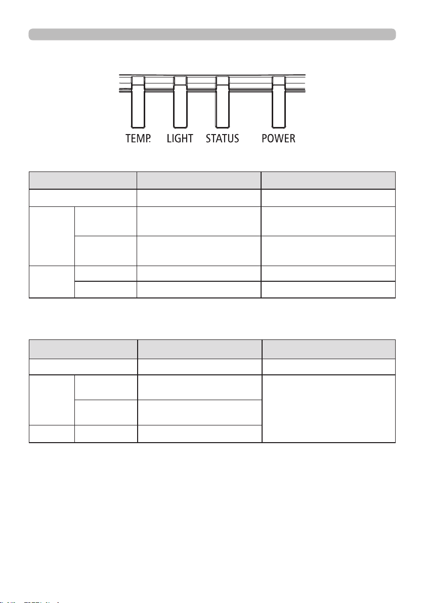
71
Troubleshoot ing
Re ga rding the indic ator
Troubleshoot ing
POWER LED
LED Display Projector Status Procedure
Off Power is off
Flashing
Green Projector warming up
Wait until projector starts
displaying.
Orange Projector cooling
Wait until cooling nishes.
( ~ 125 sec.)
On
Red Standby mode
Green Projector is on
STATUS LED
LED Display Projector Status Procedure
Off No Problem
Flashing
Red
(Cycles of 1)
Cover Error / Lens Error
If the problem occurs again
after retrying, contact your
dealer or service.
Red
(Cycles of 4)
Fan Error
On Red Standby mode with error
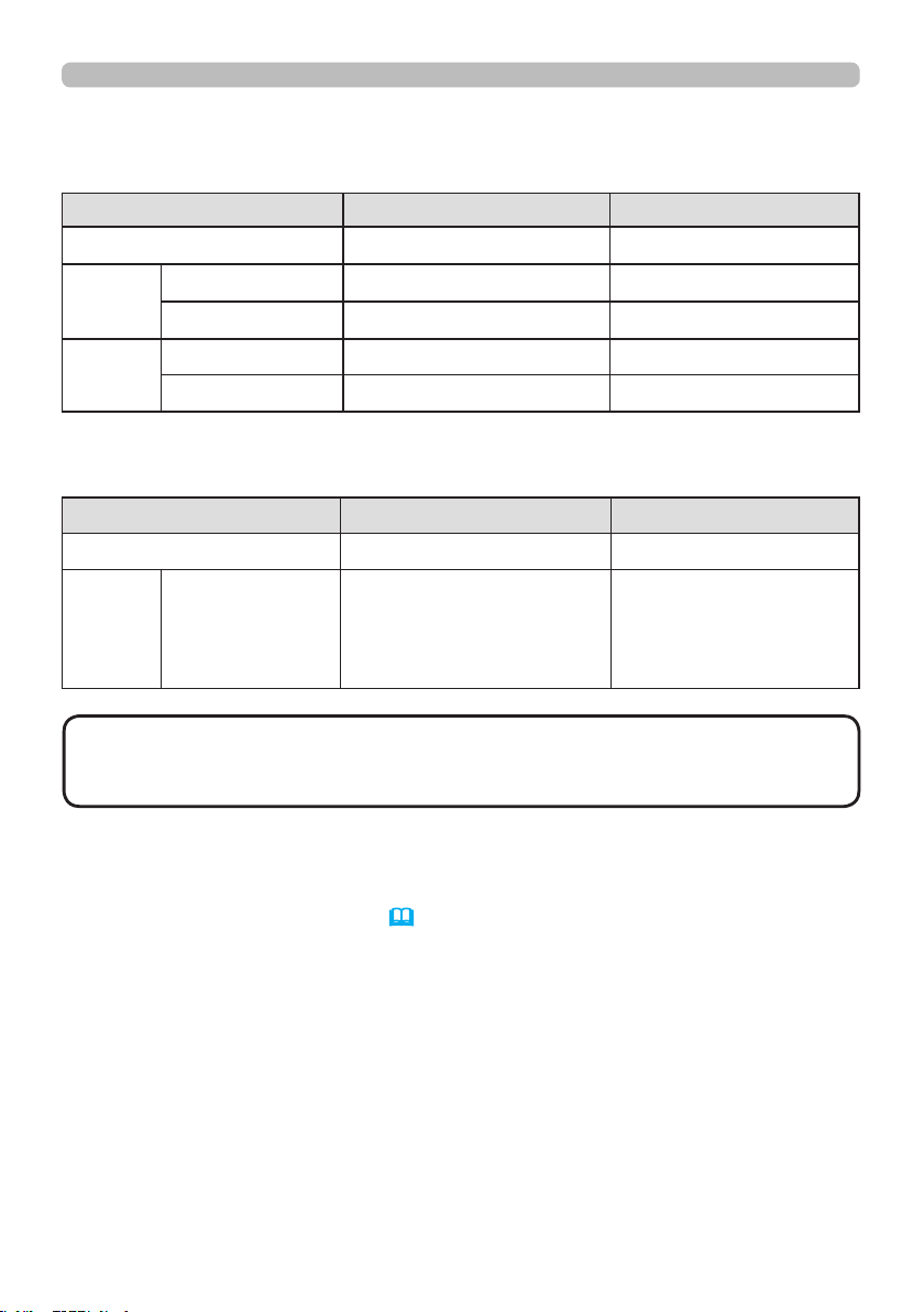
72
Troubleshoot ing
Regarding the indicator (continued)
LIGHT LED
LED Display Projector Status Procedure
Off Laser is off
Flashing
Green Prepare to light laser
Red (Cycles of 6) Laser lit fail
On
Red Laser is end-of-life
Green Laser is on
TEMP. LED
LED Display Projector Status Procedure
Off No Problem
Flashing Red Temperature problem
If the problem occurs
again after retrying,
contact your dealer or
service.
• The time period of each step in the above LED blinking pattern is 0.5
seconds, e.g., for “Cooling / Warming up” state, the green LED will ON for 0.5
seconds, and then OFF 0.5 seconds, and then repeat the above LED pattern.
NOT E
Rese tt ing a ll set tings
When it is hard to correct some wrong settings, the FACTORY RESET function of
SERVICE item in OPTION menu (61) can reset all settings (except settings such
as LANGUAGE, LASER TIME, STANDBY MODE, and NETWORK) to the factory
default.

73
Troubleshoot ing
Phenom ena that m ay be ea sy to be mist aken for ma chine defec ts
About the phenomenon confused with a machine defect, check and cope with it
according to the following table.
Phenomenon Cases not involving a machine defect
Reference
page
Power does not
come on.
The power switch is set to "
○
". Flip the switch to "
|
".
20
The electrical power cord is not plugged in.
Correctly connect the power cord.
19
The main power source has been interrupted during
operation such as by a power outage (blackout), etc.
Disconnect the power plug from the power outlet, and
allow the projector to cool down at least 20 minutes, then
turn the power on again.
19
No pictures are
displayed.
Signal source does not correctly work.
Correctly set up the signal source device by referring to
the manual of the source device.
–
The input changeover settings are mismatched.
Select the input signal, and correct the settings.
25
The signal cables are not correctly connected.
Correctly connect the connection cables.
13 ~ 17
The brightness is adjusted to an extremely low level.
Adjust BRIGHTNESS to a higher level using the menu
function.
48
The computer cannot detect the projector as a plug
and play monitor.
Make sure that the computer can detect a plug and play
monitor using another plug and play monitor.
13
The BLANK screen is displayed.
Press AV MUTE button on the remote control.
39
(continued on next page)

74
Phenomenon Cases not involving a machine defect
Reference
page
The remote
control does not
work.
The batteries in the remote control are near the end.
Replace the batteries.
21
The ID numbers set in the projector and the remote
control are different.
Press the ID button with the same ID number as the
projector, then perform the desired operation. The ID number
set in the projector can be displayed by pressing any of the
ID buttons on the remote control for 3 seconds while the
light source is on.
22
Video screen
display freezes.
The FREEZE function is working.
Press FREEZE button to restore the screen to normal.
39
Colors have
a faded-out
appearance,
or color tone is
poor.
Color settings are not correctly adjusted.
Perform picture adjustments by changing the COLOR TEMP,
COLOR and/or TINT settings, using the menu functions.
48, 50
COLOR SPACE setting is not suitable.
Change the COLOR SPACE setting.
53
Pictures appear
dark.
The brightness and/or contrast are adjusted to an
extremely low level.
Adjust BRIGHTNESS and/or CONTRAST settings to a
higher level using the menu function.
48
The projector is operating in Eco mode.
Set ECO MODE in the SETUP menu to NORMAL.
55
The light source is approaching the end of its
product lifetime.
Contact your dealer.
–
Pictures appear
blurry.
The lens cover is attached.
Remove the lens cover.
–
Either the focus and/or horizontal phase settings are
not properly adjusted.
Adjust the focus using the FOCUS + / - buttons, and/or H
PHASE using the menu function.
27, 52
The lens is dirty or misty.
Clean the lens referring to the section Caring for the lens.
68
(continued on next page)
Troubleshoot ing
Phenomena that may be easy to be mistaken for machine defects (continued)

75
Phenomenon Cases not involving a machine defect
Reference
page
Some kind
of image
degradation
such as
ickering or
stripes appear
on screen.
Flicker may appear on screen
Switch the light source ON and OFF, or try to switch the
ECO MODE once from NORMAL to ECO.
24, 55
The OVER SCAN is necessary.
Change OVER SCAN to Crop or Zoom in the IMAGE
menu.
52
Excessive NOISE REDUCTION.
Change the setting of NOISE REDUCTION in the INPUT
menu.
53
Network does
not work.
The SAVING function is working.
Select NORMAL for STANDBY MODE item in the
SETUP menu.
56
(continued on next page)
Troubleshoot ing
Phenomena that may be easy to be mistaken for machine defects (continued)

76
Phenomenon Cases not involving a machine defect
Reference
page
The IR and
RS-232C does
not work on
HDBaseT
connection.
The SAVING function is working.
Select NORMAL for STANDBY MODE item in the
SETUP menu.
56
HDBaseT
connection
does not work.
The SAVING function is working.
Select NORMAL for STANDBY MODE item in the
SETUP menu.
56
The connected equipment may not be supported by
HDBaseT.
Refer to User's manual(detailed) for connection.
15
LAN does not
work, if LAN is
connected to
the projector
while having
an input signal
from HDBaseT.
This projector is compatible with 100BASE-T only.
Check the specication of the connected equipments.
–
If the LAN cable is connected with the hub, try to change
the connected port at the hub.
–
If the LAN cable is connected directly to the computer,
try to connect to other computer.
–
(continued on next page)
Troubleshoot ing
Phenomena that may be easy to be mistaken for machine defects (continued)

77
Troubleshoot ing
Phenomenon Cases not involving a machine defect
Reference
page
No image is
displayed via
HDBaseT.
Check the LAN cable if it is CAT5e certied or higher.
–
Try to change the LAN cable.
–
If the LAN cable is connected with more than 3 extension
connector, the transmission of 100 meters may fail.
–
Check if the extension connector is compatible with
CAT5e.
All LAN cable and extension connector connected with
HDBaseT port must be CAT5e certied.
–
No image is
displayed via
SDI.
Check if it is connected with a cable of 5CFB or greater,
or Belden 1694A or greater.
–
Check if a cable with a length of 100m or less is used.
–
Try to change the cable.
–
Check if a supported signal format is input.
–
(continued on next page)
Phenomena that may be easy to be mistaken for machine defects (continued)
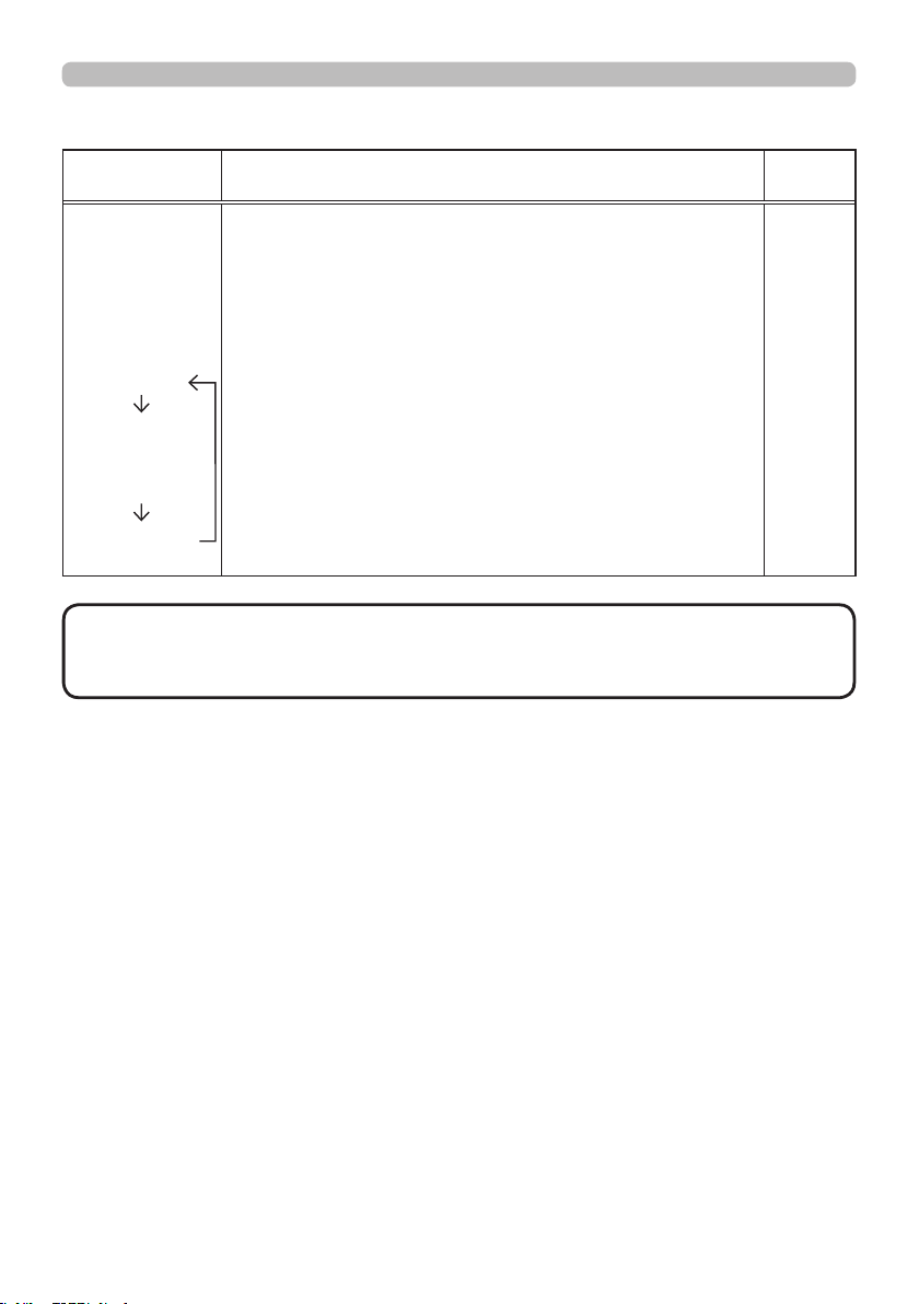
78
• Although bright spots or dark spots may appear on the screen, this is
a unique characteristic of panel, and it does not constitute or imply a machine
defect.
NOT E
Phenomenon Cases not involving a machine defect
Reference
page
When the
projector is
connected to
the network, it
powers off and
on as described
below.
Powers off
POWER
indicator blinks
in orange a few
times
Goes into
standby mode
Disconnect the LAN cable and check that the
projector is working properly.
If this phenomenon occurs after connecting to the
network, there may be a loop between two Ethernet
switching hubs within the network, as explained below.
- There are two or more Ethernet switching hubs in a
network.
- Two of the hubs are doubly connected by LAN cables.
- This double connection forms a loop between the two
hubs.
Such a loop may have an adverse effect on the projector
as well as the other network devices.
Check the network connection and remove the loop by
disconnecting the LAN cables such that there is only one
connecting cable between two hubs.
–
Troubleshoot ing
Phenomena that may be easy to be mistaken for machine defects (continued)

79
Specications
Specications
Description Specications
Resolution 1920 × 1200 (Native)
Micro display 1 x 0.67" WUXGA DMD
Light source
Laser Diode:
Green and Red by laser phosphor
Blue by diffuse laser
Projection lens -
projection ratio
FL-920 (0.38 : 1 100-350inch)
USL-901A (0.8~1.0 : 1 50-600inch)
SL-902 (1.1~1.7 : 1 50-600inch)
SD-903 (1.6~2.4 : 1 50-600inch)
ML-904 (2.4~3.6 : 1 50-600inch)
LL-905 (3.5~5.6 : 1 50-600inch)
UL-906 (5.5~8.8 : 1 50-600inch)
Input/Output ports
1 x 12V OUTPUT (DC OUTPUT JACK)
1 x Computer In (5BNC RGBHV/YPbPr/YCbCr)
1 x COMPUTER IN (D-SUB)
1 x RS-232
1 x Wire Remote
1 x HDBaseT/LAN
2 x HDMI
1 x DVI -D
1 x SDI(IN/OUT)
Primary voltage range 100V - 130V / 200V - 240V
Standby power
consumption
0.5W max power when Standby Power setting is disabled
Maximum input resolution 1920 × 1200
(continued on next page)

80
Specications
Specications (continued)
Description Specications
Operating temperature
0~45°C
Sea level Mode: 0 to 4000ft.
0 ~36℃ (100% LD power)
37~40℃ (80% LD power)
41~45℃ (70% LD power)
High Altitude Mode1: 4000 to 5500ft.
0 ~30℃ (100% LD power)
31~36℃ (90% LD power)
37~40℃ (80% LD power)
41~45℃ (70% LD power)
High Altitude Mode2: 5500 to 10000ft.
0 ~25℃ (100% LD power)
26~30℃ (90% LD power)
31~36℃ (80% LD power)
37~40℃ (70% LD power)
41~45℃ (60% LD power)
High Altitude Mode3: 10000 to 13780ft.
0 ~25℃ (100% LD power)
26~30℃ (90% LD power)
31~36℃ (80% LD power)
37~40℃ (70% LD power)
41~45℃ (60% LD power)
Relative Humidity: Operation 0~80% w/o condensing
Weight 28 kg (Without PJ Lens)
Optional parts
Lens
FL-920 support metal
FL-920 (Reective throw lens and support metal)
USL-901A (Short throw lens)
SL-902 (Short throw lens)
SD-903 (Standard lens)
ML-904 (Middle throw lens)
LL-905 (Long throw lens)
UL-906 (Ultra long throw lens)
Ceiling mount equipment
HAS-304H (Long ceiling mount)
HAS-204L (Standard ceiling mount)
HAS-104S (Short ceiling mount)
HAS-404U (Ceiling mount with 6-axis adjustment)
HAS-L9750 (Attachment bracket)

81
End U se r Lic e nse Agree m ent for t he Project or Softw are
• Software in the projector consists of the plural number of independent software
modules and there exist our copyright and/or third party copyrights for each of
such software modules.
• Be sure to read “End User License Agreement for the Projector Software” which
is separated document.
Trademark acknowledgment
• VESA and DDC are trademarks of the Video Electronics Standard Association.
•
HDMI
TM
, the HDMI logo, and High-Denition Multimedia Interface are trademarks or registered
trademarks of HDMI Licensing LLC in the United States and other countries.
• Blu-ray Disc
TM
and Blu-ray
TM
are trademarks of Blu-ray Disc Association.
• DICOM
®
is the registered trademark of the National Electrical Manufacturers Association
for its standards publications relating to digital communications of medical information.
• HDBaseT
TM
and the HDBaseT Alliance logo are trademarks of the HDBaseT Alliance.
• DLP and Digital Micromirror Device (DMD) are trademarks of Texas Instruments. Others
are copyrights of their respective companies or organizations.
• Crestron
®
, Crestron e-Control
®
, e-Control
®
,Crestron Connected
TM
, Fusion RV
®
,Crestron
RoomView
®
and RoomView
TM
are trademarks or registered trademarks of Crestron
Electronics, Inc. in the United States and other countries.
• Trademark PJLink is a trademark applied for trademark rights in
Japan, the United States of America and other countries and areas.
All other trademarks are the properties of their respective owners.
Specications