Loading ...
Loading ...
Loading ...
14
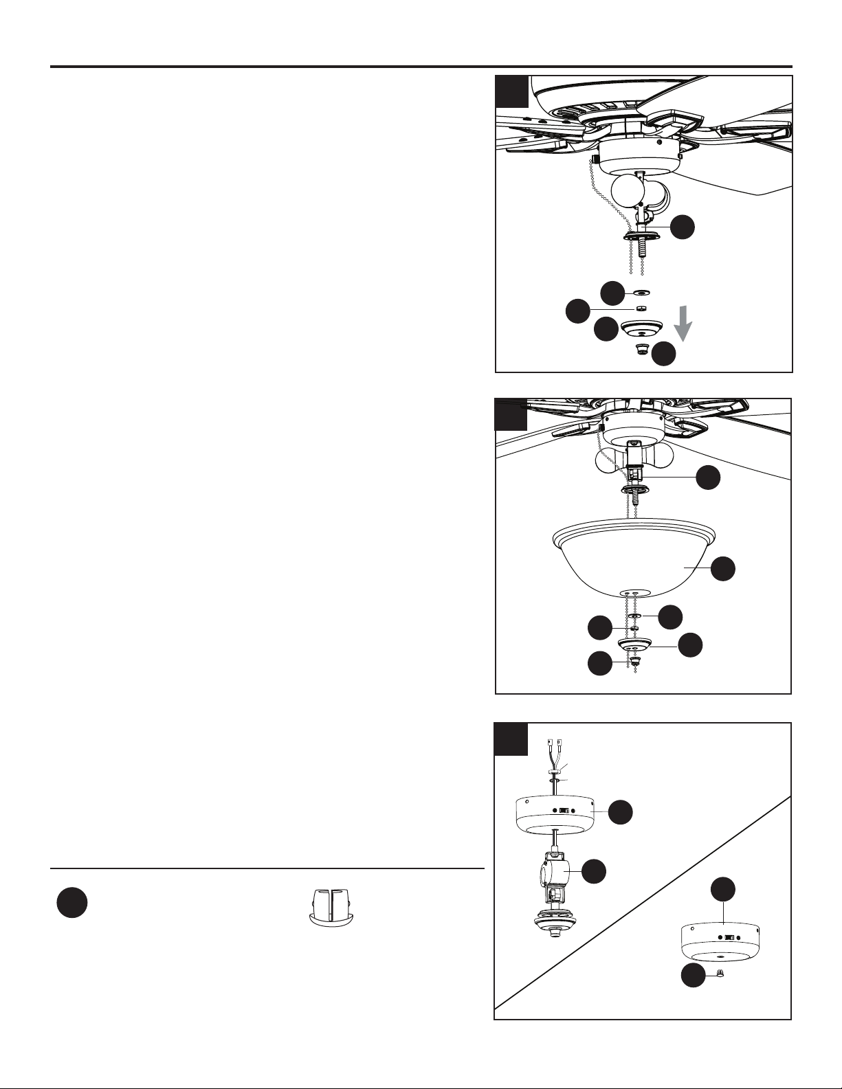
FINAL INSTALLATION
7. Remove the preassembled nial (L), nial cap (K), hex
nut (T) and rubber washer (U) from the light kit (J). Feed
the pull chain from the switch housing (I) down through
the preassembled grommet on the lower part of the light
kit (K).
8. Lift the glass bowl (N) onto the threaded rod at the
bottom of the light kit (J). Feed the pull chain coming
from the grommet in the light kit (J) through the o-
center hole in the glass bowl (N). Feed pull chain
coming from the center of the light kit (J) through the
center hole in the glass bowl (N). Secure glass bowl
(N) with rubber washer (U) and hex nut (T). Then attach
nial cap (K) and nial (L).
Proceed to Step 11.
9. To install the fan without the light kit (J), remove
the preassembled hex nut and lock washer from the
threaded rod on the inside of the switch housing (I).
Remove light kit (J) from the switch housing (I) and
discard, then install the plug button (EE) into the center
hole of the switch housing (I).
Hardware Used
EE
Plug Button x 1
8
I
EE
I
J
U
N
J
U
T
K
L
J
T
K
L
7
9
Hex Nut
Lock Washer
Loading ...
Loading ...
Loading ...