
Loading ...
Loading ...
Loading ...
3. Using the anti-tip bracket as a template, mark the two holes for either a Floor
Wood, Floor Concrete, or Wall installation, as shown.
a
b
c
d
e
a
Distance from
Adjacent Cabinet (³⁄₈"
to ¹⁄₂" [0.95 to 1.27 cm])
b
Wall Holes
c Concrete Floor Holes
d Wood Floor Holes
e
Rear Range Foot
4.
Drill two pilot holes where marked. Follow the instructions specic to your
construction.
NOTE: A nail or awl may be used to create a pilot hole, if a drill is not available.
For concrete construction ¹⁄₄" x 1¹⁄₂" Lag Bolts and ¹⁄₂" O.D. Sleeve Anchor
s are
required.
Wood
•
Floor - Drill a ¹⁄₈" pilot hole, as shown.
NOTE: Contact a qualied oor covering installer for the best procedure for
drilling mounting holes through your type of oor covering.
•
Wall - Drill an angled ¹⁄₈" pilot hole, as shown.
Concrete
•
Drill the size hole recommended for the anchors into the concrete at the
center of the holes identied as Floor Concrete or Wall.
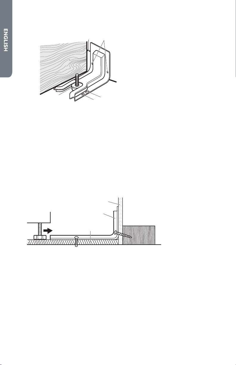
a
b
c
a
Wall
b
Anti-tip
Bracket
c
Floor
5. Install the anti-tip bracket.
Wood
•
Using the two screws (provided) fasten the anti-tip bracket to the oor or
wall.
NOTE: The screw must enter wood or metal.
Concrete
•
Insert the sleeve anchor into the drilled holes and then insert the lag bolts
through the anti-tip bracket and into the oor or wall. The bolts must be
properly tightened as recommended for the hardware.
6. Complete the range installation following the Installation Instructions
(provided).
16
Loading ...
Loading ...
Loading ...