USER GUIDE & SERVICE MANUAL
SAFETY • INSTALLATION & INTEGRATION • OPERATING INSTRUCTIONS • MAINTENANCE • SERVICE
2000 Series •
2224DWR •
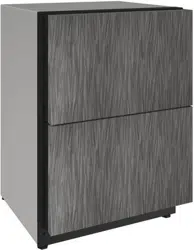
24" Drawer Model
RIGHT PRODUCT. RIGHT PLACE. RIGHT TEMPERATURE. SINCE 1962.
USER GUIDE
u-line.com
Contents
SAFETY • INSTALLATION & INTEGRATION • OPERATING INSTRUCTIONS • MAINTENANCE • SERVICE
Intro
Safety
Safety and Warning
Disposal and Recycling
Installation
Environmental Requirements
Electrical
Cutout Dimensions
Product Dimensions
Anti-Tip Bracket
General Installation
Integrated Panel Dimensions
Integrated Grille / Plinth Dimensions
Integrated Panel Installation
Grille / Plinth Installation
Drawers
Operating Instructions
First Use
Control Operation
Sabbath Mode
Airflow and Product Loading
Maintenance
Cleaning
Cleaning Condenser
Extended Non-Use
Service
Troubleshooting
Warranty
Service Extended
Wire Diagram
Product Liability
Warranty Claims
Parts
Ordering Replacement Parts
System Diagnosis Guide
Compressor Specifications
Troubleshooting Extended
Control Quick Guide
Thermistor
Defrost
Remove Fan and Cover
USER GUIDE
Introduction 1
u-line.com
WELCOME TO U-LINE
Congratulations on your U-Line purchase. Your product comes from a company with over five decades of premium modular
ice making, refrigeration, and wine preservation experience. U-Line continues to be the American leader, delivering versatility
and flexibility for multiple applications including residential, light commercial, outdoor and marine use. U-Line’s complete
product collection includes Wine Captain
®
Models, Beverage Centers, Clear Ice Machines, Crescent Ice Makers, Glass & Solid
Door Refrigerators, Drawer Models, Freezers, Combo
®
Models, and more.
U-Line has captivated those with an appreciation for the finer things with exceptional functionality, style, inspired innovations
and attention to even the smallest details. We are known and respected for our unwavering dedication to product design,
quality and selection. U-Line is headquartered in Milwaukee, Wisconsin and has shipped product to five continents for over
two decades and is proud to have the opportunity to ship to you.
PRODUCT INFORMATION
Looking for additional information on your product? User Guides, Quick Reference Guides, CAD Drawings, Compliance
Documentation, and Product Warranty information are all available for reference and download at u-line.com.
PROPERTY DAMAGE / INJURY CONCERNS
In the unlikely event property damage or personal injury is suspected related to a U-Line product, please take the following
steps:
1. U-Line Customer Care must be contacted immediately at +1.800.779.2547.
2. Service or repairs performed on the unit without prior written approval from U-Line is not permitted. If the unit has been
altered or repaired in the field without prior written approval from U-Line, claims will not be eligible.
GENERAL INQUIRIES
U-Line Corporation
8900 N. 55th Street
Milwaukee, Wisconsin 53223 USA
Monday - Friday 8:00 am to 4:30 pm CST
T: +1.414.354.0300
F: +1.414.354.7905
Email: sales@u-line.com
u-line.com
SERVICE & PARTS ASSISTANCE
Monday - Friday 8:00 am to 4:30 pm CST
T: +1.800.779.2547
F: +1.414.354.5696
Service Email: onlineservice@u-line.com
Parts Email: onlineparts@u-line.com
CONNECT WITH US
Designed, engineered and assembled in WI, USA
USER GUIDE
Safety and Warning 1
u-line.com
SAFETY • I NSTALLATION & I NTEGRATION • OPERATING I NSTRUCTIONS • MAINTENANCE • SERVICE
Safety and Warning
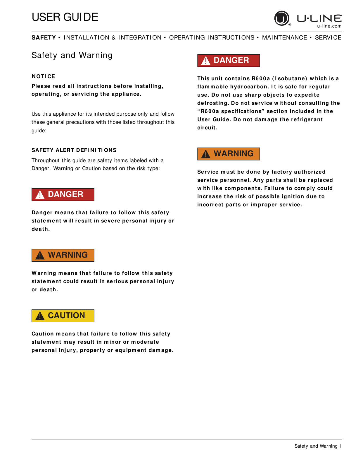
N OTI CE
Ple ase r ea d all inst r uct ions before inst a lling,
ope r a t ing, or se r vicing t he applian ce .
Use this appliance for its intended purpose only and follow
these general precautions with those listed throughout this
guide:
SAFETY ALERT DEFI NI TI ON S
Throughout this guide are safety items labeled with a
Danger, Warning or Caution based on the risk type:
DANGER
!
Dange r m e a ns t h a t fa ilure t o follow this safe t y
st a t e m ent w ill re sult in se vere pe rsona l inj ur y or
de a t h.
WARNING
!
W a rning m e a ns t h a t fa ilu r e t o follow this sa fet y
st a t e m ent could result in se r ious per sona l inj ury
or deat h.
CAUTION
!
Ca ut ion m ea n s t hat fa ilure t o follow t his sa fe t y
st a t e m ent m a y re sult in m inor or m ode r at e
persona l inj ury, propert y or equ ipm e nt da m a ge.
DANGER
!
This unit cont a ins R6 0 0 a ( I sobut a ne ) w hich is a
flam m a ble hydr oca rbon. I t is safe for re gular
use. Do not use shar p obj e ct s t o ex pe dite
de frost ing. Do not service w ithout consult ing t he
“ R6 0 0 a specifica t ion s” se ct ion included in the
Use r Guide. Do not da m age the refrigera nt
circu it .
WARNING
!
Se r vice m ust be done by fa ct or y aut h or ized
service personnel. Any part s shall be repla ce d
w it h lik e com pon e nt s. Fa ilure t o com ply could
incr e a se t h e risk of possible ignition due t o
incor r e ct pa rt s or im pr oper se r vice.
USER GUIDE
Disposal and Recycling 1
u-line.com
SAFETY • INSTALLATION & INTEGRATION • OPERATING INSTRUCTIONS • MAINTENANCE • SERVICE
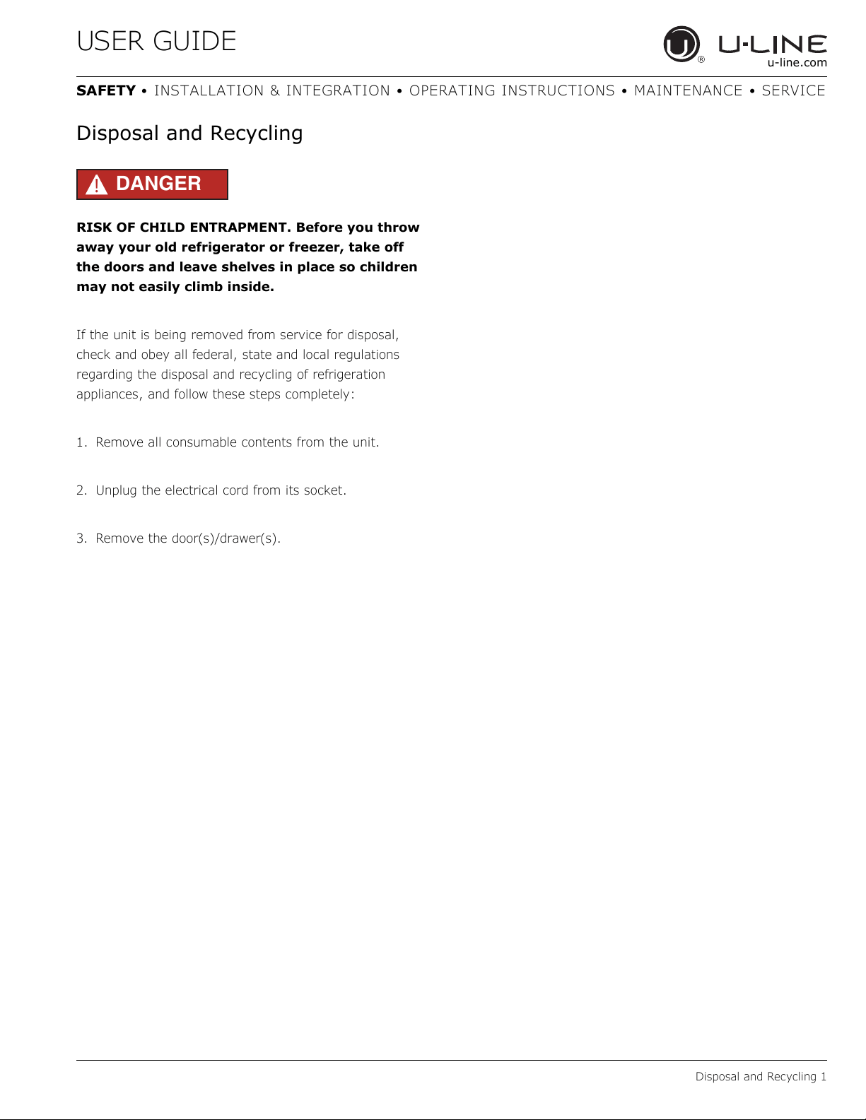
Disposal and Recycling
DANGER
!
RISK OF CHILD ENTRAPMENT. Before you throw
away your old refrigerator or freezer, take off
the doors and leave shelves in place so children
may not easily climb inside.
If the unit is being removed from service for disposal,
check and obey all federal, state and local regulations
regarding the disposal and recycling of refrigeration
appliances, and follow these steps completely:
1. Remove all consumable contents from the unit.
2. Unplug the electrical cord from its socket.
3. Remove the door(s)/drawer(s).
USER GUIDE
Environmental Requirements 1
u-line.com
SAFETY • INSTALLATION & INTEGRATION • OPERATING INSTRUCTIONS • MAINTENANCE • SERVICE
Environmental Requirements
This model is intended for indoor/interior applications only
and is not to be used in installations that are open/
exposed to natural elements.
This unit is designed to operate between 50°F (10°C) and
100°F (38°C). Higher ambient temperatures may reduce
the unit’s ability to reach low temperatures and/or reduce
ice production on applicable models.
For best performance, keep the unit out of direct sunlight
and away from heat generating equipment.
In climates where high humidity and dew points are
present, condensation may appear on outside surfaces.
This is considered normal. The condensation will
evaporate when the humidity drops.
CAUTION
!
Damages caused by ambient temperatures of
40°F (4°C) or below are not covered by the
warranty.
USER GUIDE
Electrical 1
u-line.com
SAFETY • INSTALLATION & INTEGRATION • OPERATING INSTRUCTIONS • MAINTENANCE • SERVICE
Electrical
WARNING
!
SHOCK HAZARD — Electrical Grounding
Required. Never attempt to repair or perform
maintenance on the unit until the electricity has
been disconnected.
Never remove the round grounding prong from
the plug and never use a two-prong grounding
adapter.
Altering, cutting or removing power cord,
removing power plug, or direct wiring can cause
serious injury, fire, loss of property and/or life,
and will void the warranty.
Never use an extension cord to connect power to
the unit.
Always keep your working area dry.
NOTICE
Electrical installation must observe all state and
local codes. This unit requires connection to a
grounded (three-prong), polarized receptacle
that has been placed by a qualified electrician.
The unit requires a grounded and polarized 115 VAC,
60 Hz, 15A power supply (normal household current). An
individual, properly grounded branch circuit or circuit
breaker is recommended. A GFCI (ground fault circuit
interrupter) is usually not required for fixed location
appliances and is not recommended for your unit because
it could be prone to nuisance tripping. However, be sure
to consult your local codes.
See CUTOUT DIMENSIONS for recommended receptacle
location.
USER GUIDE
Cutout Dimensions 1
u-line.com
SAFETY • INSTALLATION & INTEGRATION • OPERATING INSTRUCTIONS • MAINTENANCE • SERVICE
Cutout Dimensions
PREPARE SITE
Your U-Line product has been designed exclusively for a
built-in installation. When built-in, your unit does not
require additional air space for top, sides, or rear.
However, the front grille must NOT be obstructed.
The product is designed and manufactured for seamless
integration in the specified cutout opening shown, which
requires precise measurements. The opening must be
square and plumb front to back. Although not required,
you may choose to increase the overall cutout width for
ease of installation.
The Modular 3000 Series units are engineered with a
variety of adjustment features to help ensure a seamless
installation. Adjustable doors, leveling legs and grille will
assist in fine tuning the installation.
All 3000 Series models fully integrate into overlay/face
frame, inset or European/frameless cabinet styles and
install seamlessly into standard 24" (610 mm) depth
cabinet base.
CAUTION
!
Unit can NOT be installed behind a closed cabinet
door.
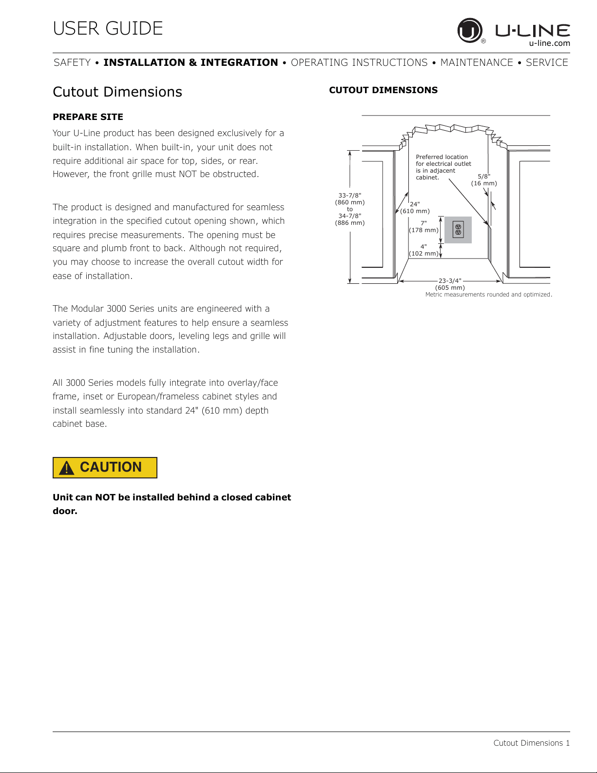
CUTOUT DIMENSIONS
Metric measurements rounded and optimized.
4"
(102 mm)
7"
(178 mm)
33-7/8"
(860 mm)
to
34-7/8"
(886 mm)
23-3/4"
(605 mm)
Preferred location
for electrical outlet
is in adjacent
cabinet.
24"
(610 mm)
5/8"
(16 mm)
USER GUIDE
Product Dimensions 1
u-line.com
SAFETY • INSTALLATION & INTEGRATION • OPERATING INSTRUCTIONS • MAINTENANCE • SERVICE
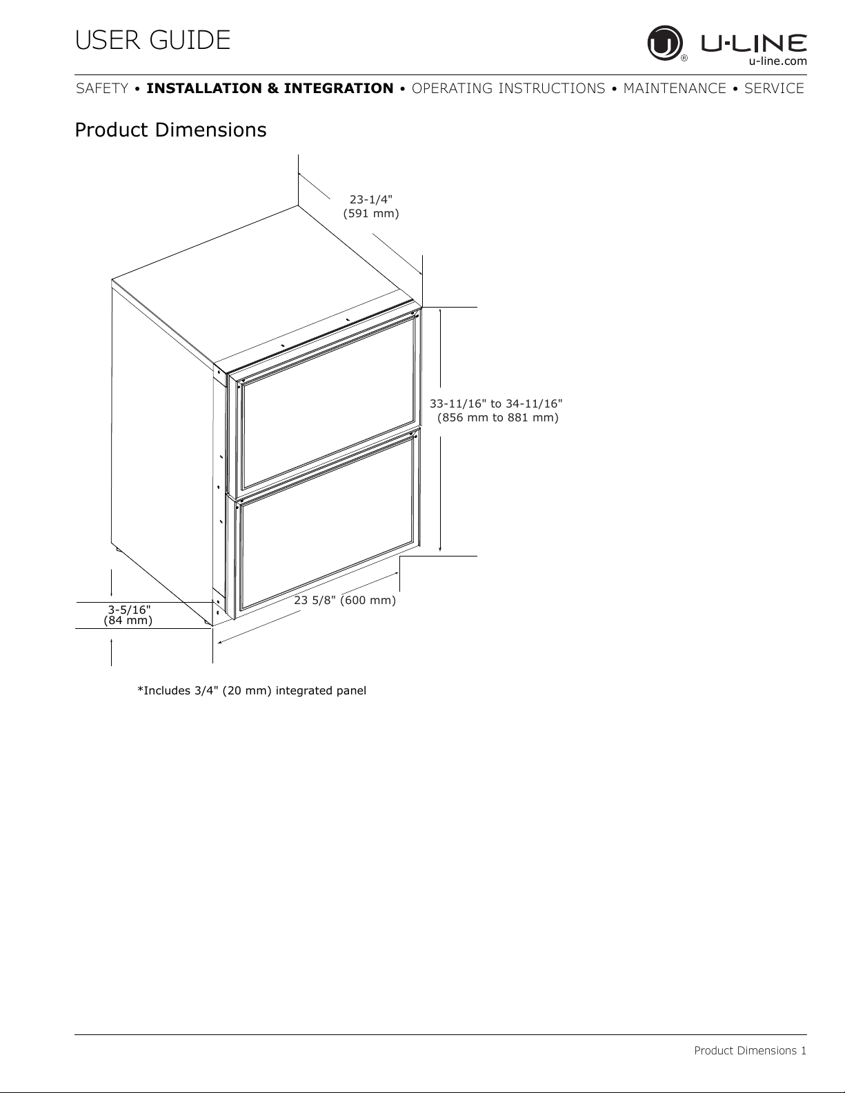
Product Dimensions
23-1/4"
(591 mm)
33-11/16" to 34-11/16"
(856 mm to 881 mm)
23 5/8" (600 mm)
*Includes 3/4" (20 mm) integrated panel
3-5/16"
(84 mm)
USER GUIDE
Anti-Tip Bracket 1
u-line.com
SAFETY • INSTALLATION & INTEGRATION • OPERATING INSTRUCTIONS • MAINTENANCE • SERVICE
Anti-Tip Bracket
CAUTION
!
The anti-tip bracket must be installed to prevent
the unit from tipping when doors are fully
opened or excess weight is placed on the front of
the unit.
The anti-tip bracket has multiple mounting options.
Mounting will depend on your particular cabinet
configuration. Locate 3 #8x5/8" screws included with your
unit.
TOP MOUNT
For ease of installation, the anti-tip bracket is pre-installed
in the top mount position.
1. Completely slide the unit into its position in the
cabinet. Be certain unit height is properly adjusted.
(See GENERAL INSTALLATION).
2. Open door completely. Make certain door clears
surrounding cabinetry.
3. Using a 3/32" (2.50 mm) drill bit, drill 3 pilot holes 5/8"
(16 mm) deep into bottom of counter top. Use the
anti-tip bracket as a template.
4. Install 3 #8x5/8" screws into the plate using a
#2 Phillips head screwdriver.
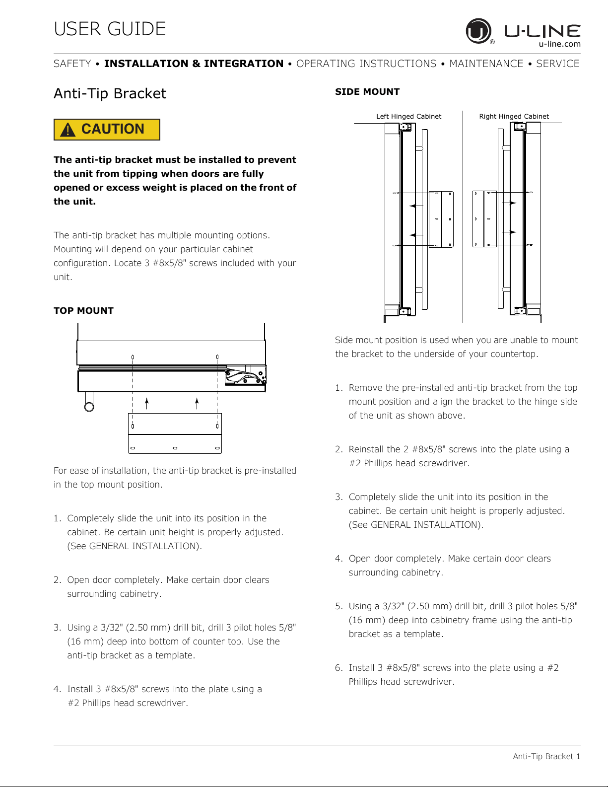
SIDE MOUNT
Side mount position is used when you are unable to mount
the bracket to the underside of your countertop.
1. Remove the pre-installed anti-tip bracket from the top
mount position and align the bracket to the hinge side
of the unit as shown above.
2. Reinstall the 2 #8x5/8" screws into the plate using a
#2 Phillips head screwdriver.
3. Completely slide the unit into its position in the
cabinet. Be certain unit height is properly adjusted.
(See GENERAL INSTALLATION).
4. Open door completely. Make certain door clears
surrounding cabinetry.
5. Using a 3/32" (2.50 mm) drill bit, drill 3 pilot holes 5/8"
(16 mm) deep into cabinetry frame using the anti-tip
bracket as a template.
6. Install 3 #8x5/8" screws into the plate using a #2
Phillips head screwdriver.
Left Hinged Cabinet
Right Hinged Cabinet
USER GUIDE
General Installation 1
u-line.com
SAFETY • INSTALLATION & INTEGRATION • OPERATING INSTRUCTIONS • MAINTENANCE • SERVICE
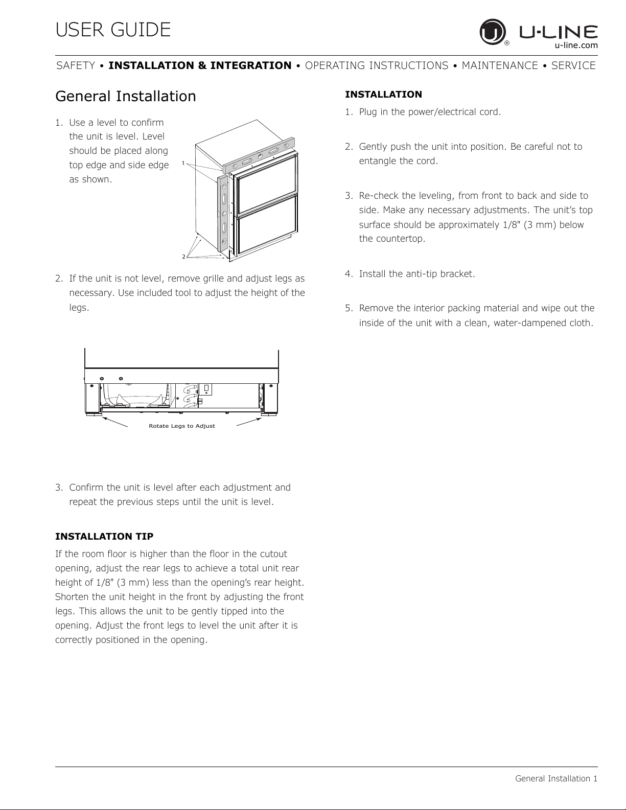
General Installation
1. Use a level to confirm
the unit is level. Level
should be placed along
top edge and side edge
as shown.
2. If the unit is not level, remove grille and adjust legs as
necessary. Use included tool to adjust the height of the
legs.
3. Confirm the unit is level after each adjustment and
repeat the previous steps until the unit is level.
INSTALLATION TIP
If the room floor is higher than the floor in the cutout
opening, adjust the rear legs to achieve a total unit rear
height of 1/8" (3 mm) less than the opening’s rear height.
Shorten the unit height in the front by adjusting the front
legs. This allows the unit to be gently tipped into the
opening. Adjust the front legs to level the unit after it is
correctly positioned in the opening.
INSTALLATION
1. Plug in the power/electrical cord.
2. Gently push the unit into position. Be careful not to
entangle the cord.
3. Re-check the leveling, from front to back and side to
side. Make any necessary adjustments. The unit’s top
surface should be approximately 1/8" (3 mm) below
the countertop.
4. Install the anti-tip bracket.
5. Remove the interior packing material and wipe out the
inside of the unit with a clean, water-dampened cloth.
1
2
Rotate Legs to Adjust
USER GUIDE
Integrated Panel Dimensions 1
u-line.com
SAFETY • INSTALLATION & INTEGRATION • OPERATING INSTRUCTIONS • MAINTENANCE • SERVICE
Integrated Panel Dimensions
Metric measurements rounded and optimized.
STANDARD PANELS
NOTICE
Due to differences in surrounding cabinetry the
panel may not perfectly align with drawer. The
procedure below is designed to provide a
finished integrated panel that seamlessly
integrates with surrounding cabinetry.
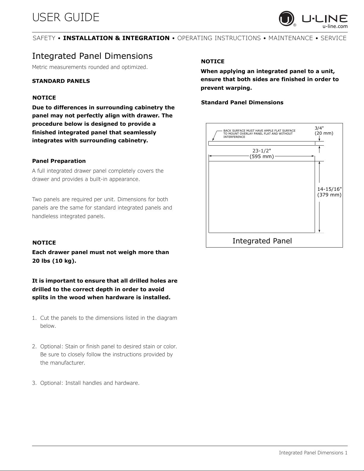
Panel Preparation
A full integrated drawer panel completely covers the
drawer and provides a built-in appearance.
Two panels are required per unit. Dimensions for both
panels are the same for standard integrated panels and
handleless integrated panels.
NOTICE
Each drawer panel must not weigh more than
20 lbs (10 kg).
It is important to ensure that all drilled holes are
drilled to the correct depth in order to avoid
splits in the wood when hardware is installed.
1. Cut the panels to the dimensions listed in the diagram
below.
2. Optional: Stain or finish panel to desired stain or color.
Be sure to closely follow the instructions provided by
the manufacturer.
3. Optional: Install handles and hardware.
NOTICE
When applying an integrated panel to a unit,
ensure that both sides are finished in order to
prevent warping.
BACK SURFACE MUST HAVE AMPLE FLAT SURFACE
TO MOUNT OVERLAY PANEL FLAT AND WITHOUT
INTERFERENCE
23-1/2"
(595 mm)
3/4"
(20 mm)
Integrated Panel
14-15/16"
(379 mm)
Standard Panel Dimensions
USER GUIDE
Integrated Panel Dimensions 2
u-line.com
SAFETY • INSTALLATION & INTEGRATION • OPERATING INSTRUCTIONS • MAINTENANCE • SERVICE
HANDLELESS INTEGRATED DRAWER PANELS
The following procedure is designed to provide a finished,
handleless solid panel for a 24" (600 mm) drawer that
seamlessly integrates with its surrounding cabinetry.
Prepare two panels for your drawer unit.
NOTE: Many cabinet manufacturers provide a ready
solution for a handleless, integrated design that can be
easily applied to your U-Line 3000 Series model. Consult
your cabinet manufacturer for applicable design and
installation details. The cabinet manufacturer’s solution to
this design and integration detail will often result in an
integrated panel solution wherein the size of the panel
may result in a height dimension taller than what we
specify. This can be achieved provided the additional
height is positioned above the appliance drawer.
NOTICE
The integrated panel aligns with the surrounding
cabinetry and, due to differences in cabinetry,
may not align perfectly with the drawer.
The appliance will need up to 34-1/2" (876 mm)
to the underside of the counter to leave room for
leveling adjustments.
Each drawer panel with insert must not weigh
more than 20 lbs (10 kg).
Integrated Panel Preparation
1. Cut the main panel to the dimensions below. For
details, see the drawings on the next page.
2. Create the top design for the handleless feature and
the 1/8" notch for the insert(s) indicated on the Top
Detail drawing.
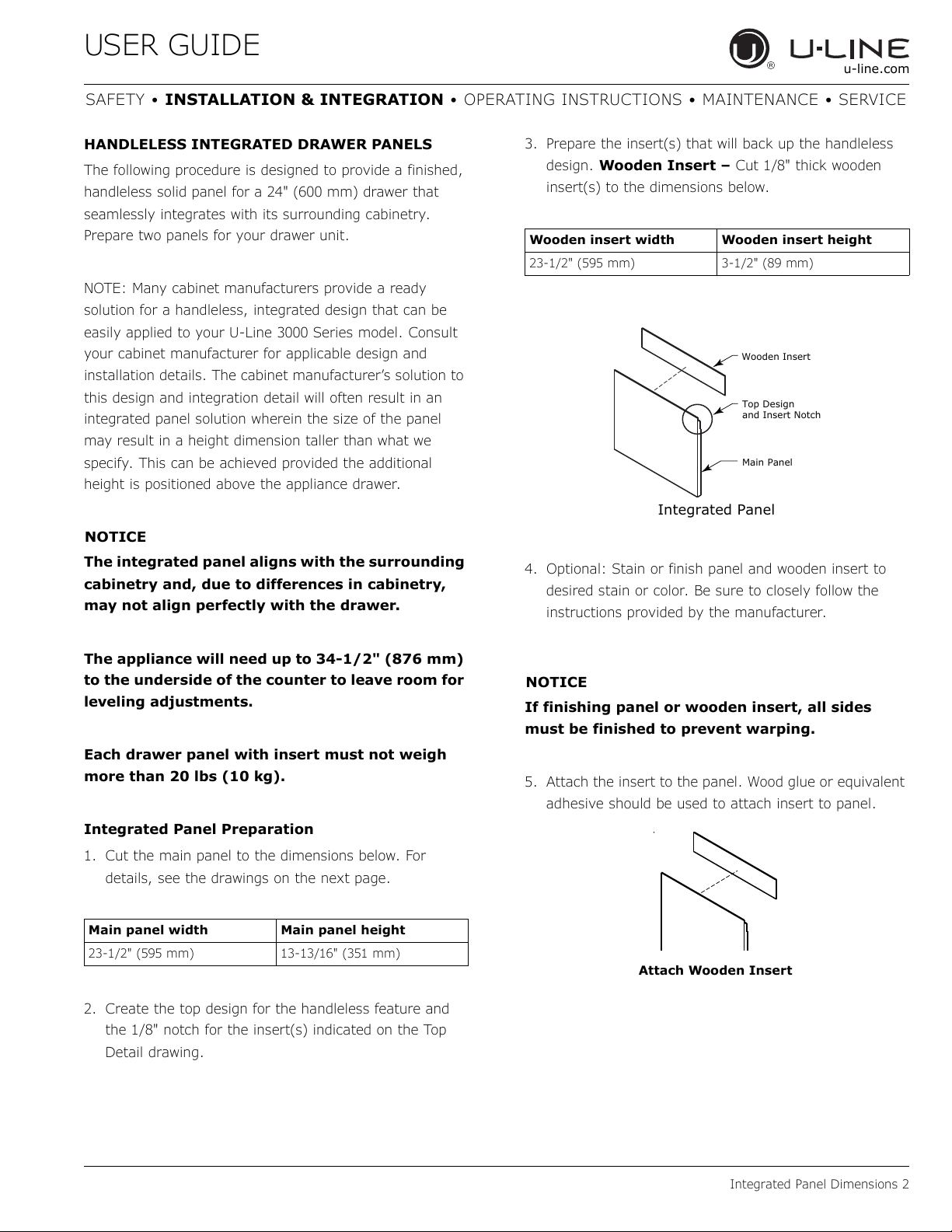
3. Prepare the insert(s) that will back up the handleless
design. Wooden Insert – Cut 1/8" thick wooden
insert(s) to the dimensions below.
4. Optional: Stain or finish panel and wooden insert to
desired stain or color. Be sure to closely follow the
instructions provided by the manufacturer.
NOTICE
If finishing panel or wooden insert, all sides
must be finished to prevent warping.
5. Attach the insert to the panel. Wood glue or equivalent
adhesive should be used to attach insert to panel.
Main panel width Main panel height
23-1/2" (595 mm) 13-13/16" (351 mm)
Wooden insert width Wooden insert height
23-1/2" (595 mm) 3-1/2" (89 mm)
Top Design
and Insert Notch
Wooden Insert
Main Panel
Integrated Panel
Attach Wooden Insert
USER GUIDE
Integrated Panel Dimensions 3
u-line.com
SAFETY • INSTALLATION & INTEGRATION • OPERATING INSTRUCTIONS • MAINTENANCE • SERVICE
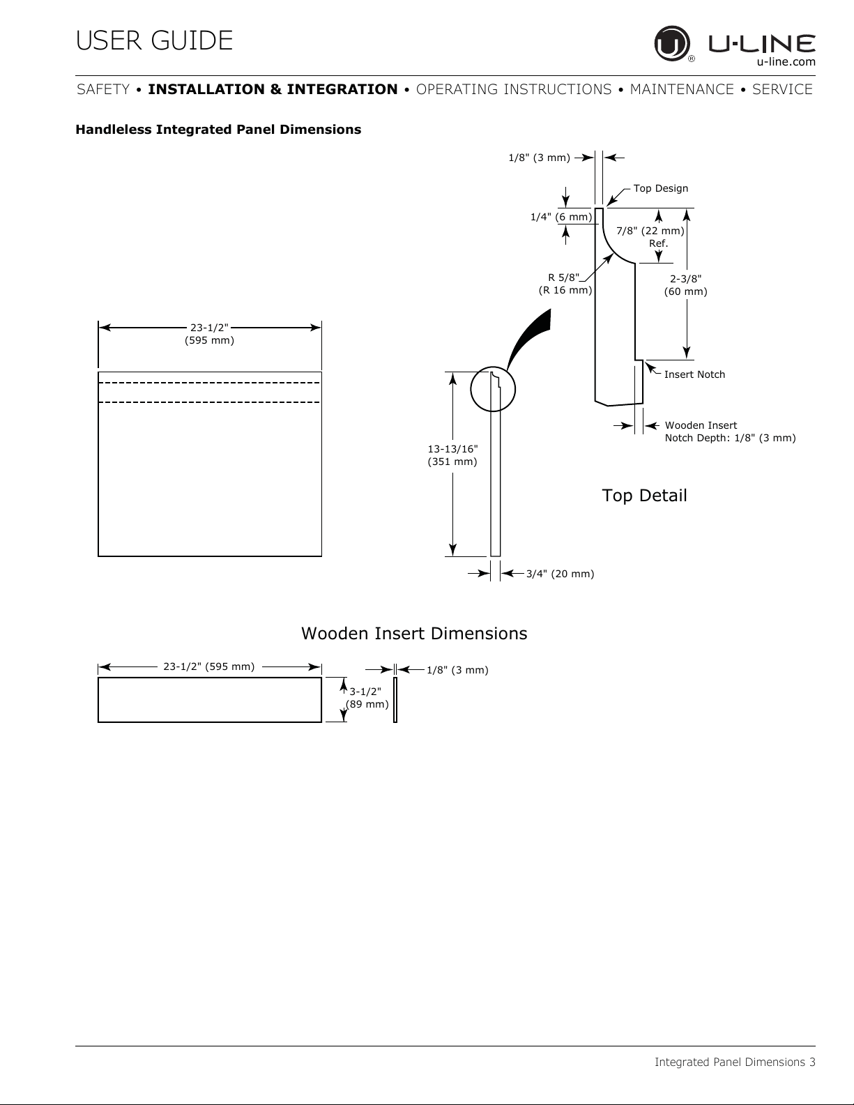
Handleless Integrated Panel Dimensions
3/4" (20 mm)
13-13/16"
(351 mm)
R 5/8"
(R 16 mm)
1/8" (3 mm)
1/4" (6 mm)
Wooden Insert
Notch Depth: 1/8" (3 mm)
2-3/8"
(60 mm)
7/8" (22 mm)
Ref.
Top Detail
Insert Notch
Top Design
1/8" (3 mm)
3-1/2"
(89 mm)
23-1/2" (595 mm)
Wooden Insert Dimensions
23-1/2"
(595 mm)
USER GUIDE
Integrated Panel Dimensions 4
u-line.com
SAFETY • INSTALLATION & INTEGRATION • OPERATING INSTRUCTIONS • MAINTENANCE • SERVICE
EXTENDED INTEGRATED PANELS
NOTICE
Due to differences in surrounding cabinetry the
panel may not perfectly align with drawer. The
procedure below is designed to provide a
finished panel that seamlessly integrates with
surrounding cabinetry.
Panel Preparation
An extended integrated panel can be used to maintain
alignment with an adjacent extended cabinet height or a
reduced toe-kick/grille application.
1. Cut the panels to the dimensions listed in the
appropriate diagram on the next page.
2. Optional: Stain or finish panel to desired stain or color.
Be sure to closely follow the instructions provided by
the manufacturer.
3. Optional: Install handles and hardware.
NOTICE
Each drawer panel must not weigh more than
20 lbs (10 kg).
It is important to ensure that all drilled holes are
drilled to the correct depth in order to avoid
splits in the wood when hardware is installed.
Appliance will need up to 34-1/2" (876 mm) to
the underside of the counter to leave room for
leveling adjustments.
When applying an integrated panel to a unit,
ensure that both sides are finished in order to
prevent warping.
USER GUIDE
Integrated Panel Dimensions 5
u-line.com
SAFETY • INSTALLATION & INTEGRATION • OPERATING INSTRUCTIONS • MAINTENANCE • SERVICE
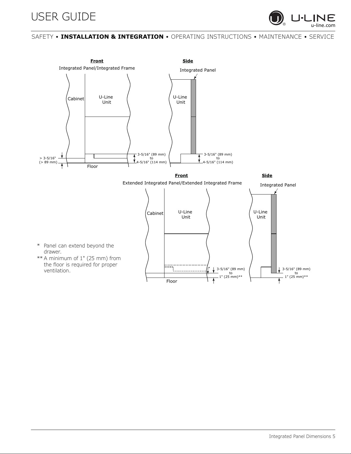
3-5/16" (89 mm)
to
4-5/16" (114 mm)
U-Line
Unit
U-Line
Unit
Integrated Panel
Integrated Panel/Integrated Frame
Front
Side
Front Side
3-5/16" (89 mm)
to
4-5/16" (114 mm)
Floor
Cabinet
> 3-5/16"
(> 89 mm)
3-5/16" (89 mm)
to
1" (25 mm)**
U-Line
Unit
Extended Integrated Panel/Extended Integrated Frame
Floor
Cabinet
3-5/16" (89 mm)
to
1" (25 mm)**
*
U-Line
Unit
Integrated Panel
* Panel can extend beyond the
drawer.
** A minimum of 1" (25 mm) from
the floor is required for proper
ventilation.
USER GUIDE
Integrated Panel Dimensions 6
u-line.com
SAFETY • INSTALLATION & INTEGRATION • OPERATING INSTRUCTIONS • MAINTENANCE • SERVICE
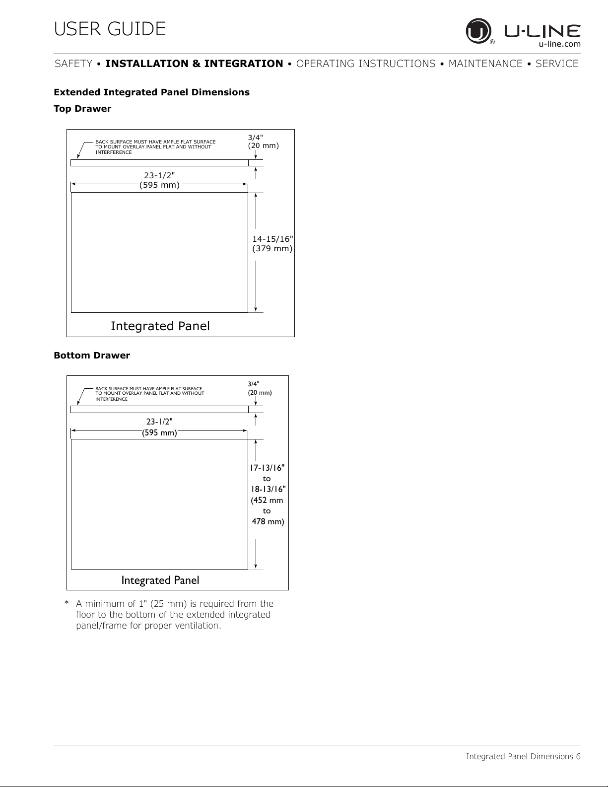
Extended Integrated Panel Dimensions
Top Drawer
Bottom Drawer
BACK SURFACE MUST HAVE AMPLE FLAT SURFACE
TO MOUNT OVERLAY PANEL FLAT AND WITHOUT
INTERFERENCE
23-1/2"
(595 mm)
3/4"
(20 mm)
Integrated Panel
14-15/16"
(379 mm)
BACK SURFACE MUST HAVE AMPLE FLAT SURFACE
TO MOUNT OVERLAY PANEL FLAT AND WITHOUT
INTERFERENCE
23-1/2"
(595 mm)
3/4"
(20 mm)
Integrated Panel
17-13/16"
to
18-13/16"
(452 mm
to
478 mm)
* A minimum of 1" (25 mm) is required from the
floor to the bottom of the extended integrated
panel/frame for proper ventilation.
USER GUIDE
Integrated Grille - Plinth Dimensions 1
u-line.com
SAFETY • INSTALLATION & INTEGRATION • OPERATING INSTRUCTIONS • MAINTENANCE • SERVICE
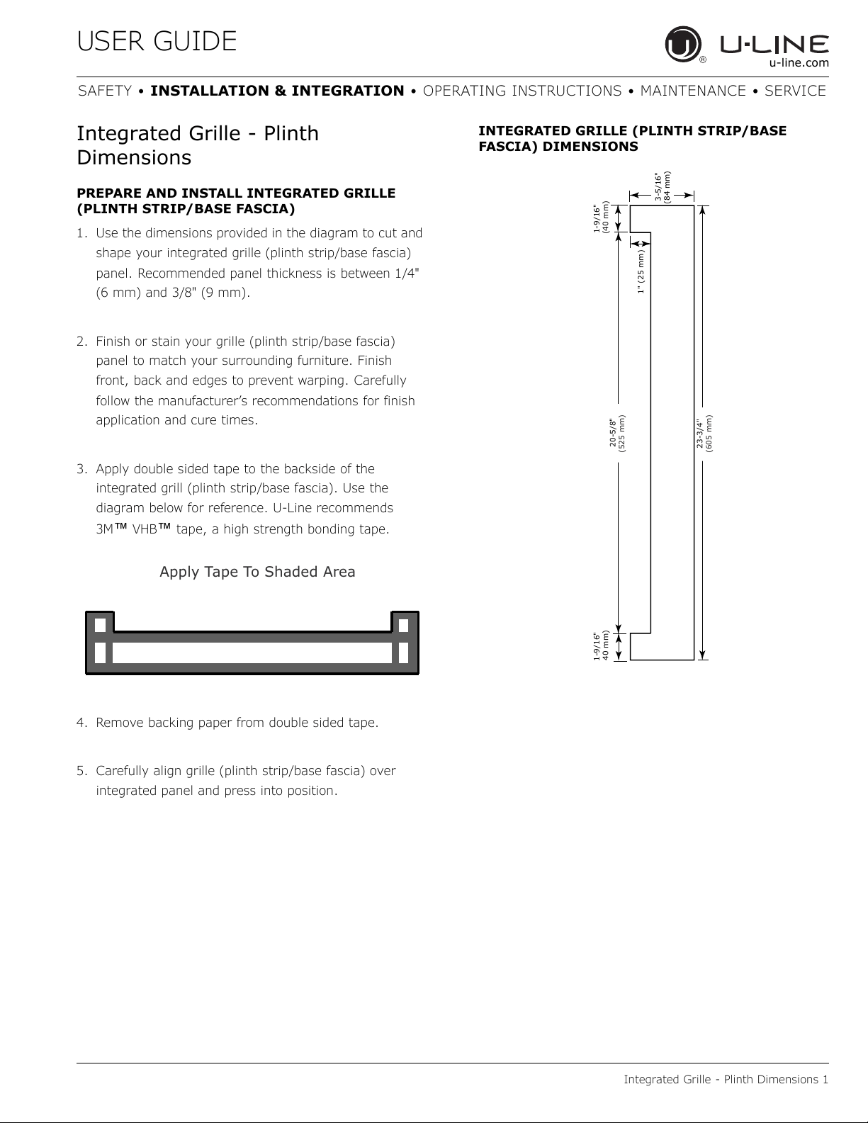
Integrated Grille - Plinth
Dimensions
PREPARE AND INSTALL INTEGRATED GRILLE
(PLINTH STRIP/BASE FASCIA)
1. Use the dimensions provided in the diagram to cut and
shape your integrated grille (plinth strip/base fascia)
panel. Recommended panel thickness is between 1/4"
(6 mm) and 3/8" (9 mm).
2. Finish or stain your grille (plinth strip/base fascia)
panel to match your surrounding furniture. Finish
front, back and edges to prevent warping. Carefully
follow the manufacturer’s recommendations for finish
application and cure times.
3. Apply double sided tape to the backside of the
integrated grill (plinth strip/base fascia). Use the
diagram below for reference. U-Line recommends
3M
™ VHB™ tape, a high strength bonding tape.
4. Remove backing paper from double sided tape.
5. Carefully align grille (plinth strip/base fascia) over
integrated panel and press into position.
INTEGRATED GRILLE (PLINTH STRIP/BASE
FASCIA) DIMENSIONS
Apply Tape To Shaded Area
23-3/4"
(605 mm)
20-5/8"
(525 mm)
1-9/16"
40 mm)
1-9/16"
(40 mm)
1" (25 mm)
3-5/16"
(84 mm)
USER GUIDE
Integrated Panel Installation 1
u-line.com
SAFETY • INSTALLATION & INTEGRATION • OPERATING INSTRUCTIONS • MAINTENANCE • SERVICE
Integrated Panel Installation
1. Fully open drawer.
2. Align top of panel with top edge of drawer. Center
panel on drawer.
NOTICE
Due to differences in floor construction or
surrounding cabinetry, the panel may not sit
flush with the top of the drawer.
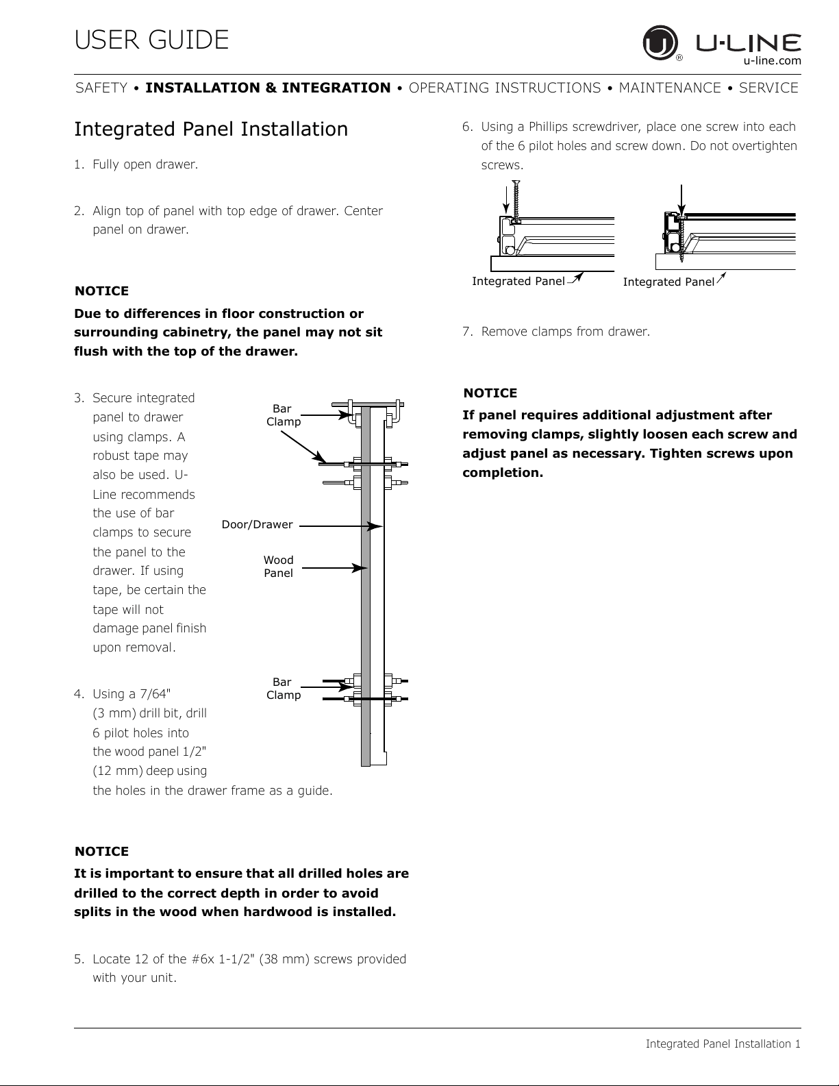
3. Secure integrated
panel to drawer
using clamps. A
robust tape may
also be used. U-
Line recommends
the use of bar
clamps to secure
the panel to the
drawer. If using
tape, be certain the
tape will not
damage panel finish
upon removal.
4. Using a 7/64"
(3 mm) drill bit, drill
6 pilot holes into
the wood panel 1/2"
(12 mm) deep using
the holes in the drawer frame as a guide.
NOTICE
It is important to ensure that all drilled holes are
drilled to the correct depth in order to avoid
splits in the wood when hardwood is installed.
5. Locate 12 of the #6x 1-1/2" (38 mm) screws provided
with your unit.
6. Using a Phillips screwdriver, place one screw into each
of the 6 pilot holes and screw down. Do not overtighten
screws.
7. Remove clamps from drawer.
NOTICE
If panel requires additional adjustment after
removing clamps, slightly loosen each screw and
adjust panel as necessary. Tighten screws upon
completion.
Wood
Panel
Door/Drawer
Bar
Clamp
Bar
Clamp
Integrated Panel
Integrated Panel
USER GUIDE
Grille - Plinth Installation 1
u-line.com
SAFETY • INSTALLATION & INTEGRATION • OPERATING INSTRUCTIONS • MAINTENANCE • SERVICE
Grille - Plinth Installation
REMOVING AND INSTALLING GRILLE
(PLINTH STRIP/BASE FASCIA)
WARNING
!
Disconnect electric power to the unit before
removing the grille (plinth strip/base fascia).
When using the unit, the grille (plinth strip/base
fascia) must be installed.
WARNING
!
DO NOT touch the condenser fins. The condenser
fins are SHARP and can be easily damaged.
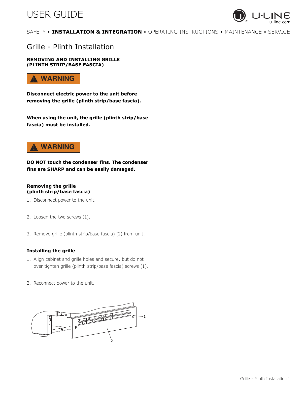
Removing the grille
(plinth strip/base fascia)
1. Disconnect power to the unit.
2. Loosen the two screws (1).
3. Remove grille (plinth strip/base fascia) (2) from unit.
Installing the grille
1. Align cabinet and grille holes and secure, but do not
over tighten grille (plinth strip/base fascia) screws (1).
2. Reconnect power to the unit.
1
2
USER GUIDE
Drawers 1
u-line.com
SAFETY • INSTALLATION & INTEGRATION • OPERATING INSTRUCTIONS • MAINTENANCE • SERVICE
Drawers
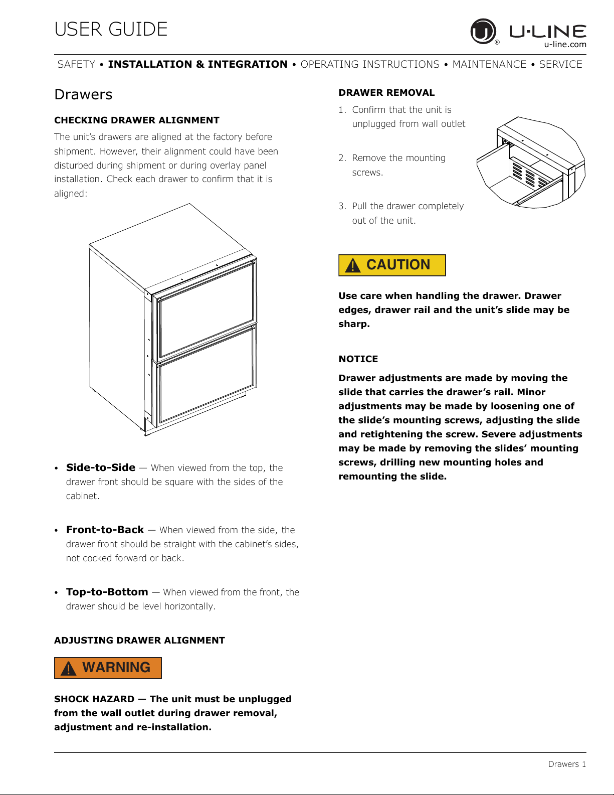
CHECKING DRAWER ALIGNMENT
The unit’s drawers are aligned at the factory before
shipment. However, their alignment could have been
disturbed during shipment or during overlay panel
installation. Check each drawer to confirm that it is
aligned:
• Side-to-Side — When viewed from the top, the
drawer front should be square with the sides of the
cabinet.
• Front-to-Back — When viewed from the side, the
drawer front should be straight with the cabinet’s sides,
not cocked forward or back.
• Top-to-Bottom — When viewed from the front, the
drawer should be level horizontally.
ADJUSTING DRAWER ALIGNMENT
WARNING
!
SHOCK HAZARD — The unit must be unplugged
from the wall outlet during drawer removal,
adjustment and re-installation.
DRAWER REMOVAL
1. Confirm that the unit is
unplugged from wall outlet
2. Remove the mounting
screws.
3. Pull the drawer completely
out of the unit.
CAUTION
!
Use care when handling the drawer. Drawer
edges, drawer rail and the unit’s slide may be
sharp.
NOTICE
Drawer adjustments are made by moving the
slide that carries the drawer’s rail. Minor
adjustments may be made by loosening one of
the slide’s mounting screws, adjusting the slide
and retightening the screw. Severe adjustments
may be made by removing the slides’ mounting
screws, drilling new mounting holes and
remounting the slide.
USER GUIDE
Drawers 2
u-line.com
SAFETY • INSTALLATION & INTEGRATION • OPERATING INSTRUCTIONS • MAINTENANCE • SERVICE
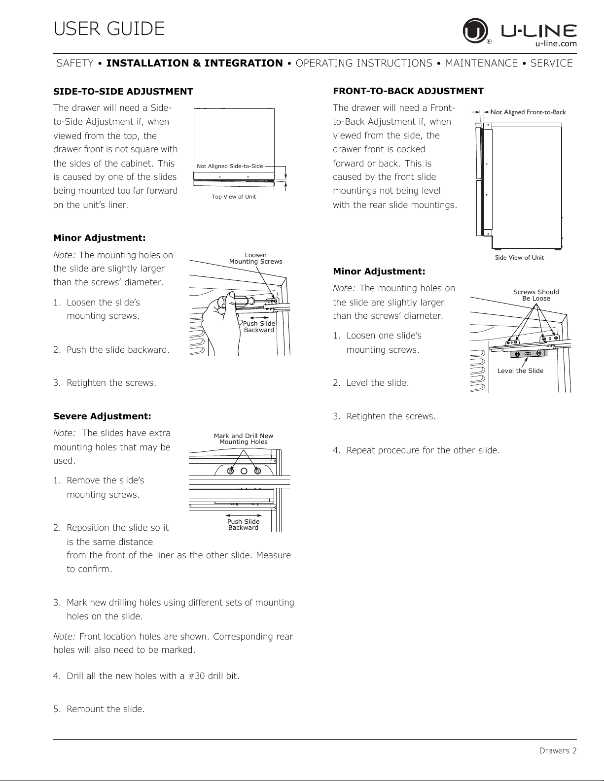
SIDE-TO-SIDE ADJUSTMENT
The drawer will need a Side-
to-Side Adjustment if, when
viewed from the top, the
drawer front is not square with
the sides of the cabinet. This
is caused by one of the slides
being mounted too far forward
on the unit’s liner.
Minor Adjustment:
Note: The mounting holes on
the slide are slightly larger
than the screws’ diameter.
1. Loosen the slide’s
mounting screws.
2. Push the slide backward.
3. Retighten the screws.
Severe Adjustment:
Note: The slides have extra
mounting holes that may be
used.
1. Remove the slide’s
mounting screws.
2. Reposition the slide so it
is the same distance
from the front of the liner as the other slide. Measure
to confirm.
3. Mark new drilling holes using different sets of mounting
holes on the slide.
Note: Front location holes are shown. Corresponding rear
holes will also need to be marked.
4. Drill all the new holes with a #30 drill bit.
5. Remount the slide.
FRONT-TO-BACK ADJUSTMENT
The drawer will need a Front-
to-Back Adjustment if, when
viewed from the side, the
drawer front is cocked
forward or back. This is
caused by the front slide
mountings not being level
with the rear slide mountings.
Minor Adjustment:
Note: The mounting holes on
the slide are slightly larger
than the screws’ diameter.
1. Loosen one slide’s
mounting screws.
2. Level the slide.
3. Retighten the screws.
4. Repeat procedure for the other slide.
Top View of Unit
Not Aligned Side-to-Side
Push Slide
Backward
Loosen
Mounting Screws
Mark and Drill New
Mounting Holes
Push Slide
Backward
Not Aligned Front-to-Back
Side View of Unit
Screws Should
Be Loose
Level the Slide
USER GUIDE
Drawers 3
u-line.com
SAFETY • INSTALLATION & INTEGRATION • OPERATING INSTRUCTIONS • MAINTENANCE • SERVICE
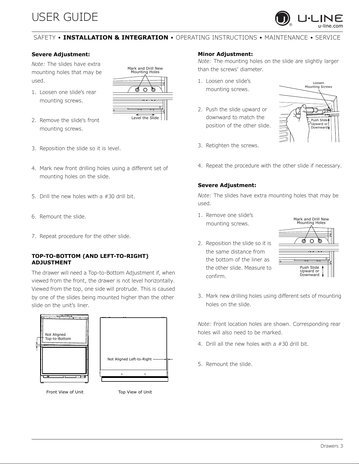
Severe Adjustment:
Note: The slides have extra
mounting holes that may be
used.
1. Loosen one slide’s rear
mounting screws.
2. Remove the slide’s front
mounting screws.
3. Reposition the slide so it is level.
4. Mark new front drilling holes using a different set of
mounting holes on the slide.
5. Drill the new holes with a #30 drill bit.
6. Remount the slide.
7. Repeat procedure for the other slide.
TOP-TO-BOTTOM (AND LEFT-TO-RIGHT)
ADJUSTMENT
The drawer will need a Top-to-Bottom Adjustment if, when
viewed from the front, the drawer is not level horizontally.
Viewed from the top, one side will protrude. This is caused
by one of the slides being mounted higher than the other
slide on the unit’s liner.
Minor Adjustment:
Note: The mounting holes on the slide are slightly larger
than the screws’ diameter.
1. Loosen one slide’s
mounting screws.
2. Push the slide upward or
downward to match the
position of the other slide.
3. Retighten the screws.
4. Repeat the procedure with the other slide if necessary.
Severe Adjustment:
Note: The slides have extra mounting holes that may be
used.
1. Remove one slide’s
mounting screws.
2. Reposition the slide so it is
the same distance from
the bottom of the liner as
the other slide. Measure to
confirm.
3. Mark new drilling holes using different sets of mounting
holes on the slide.
Note: Front location holes are shown. Corresponding rear
holes will also need to be marked.
4. Drill all the new holes with a #30 drill bit.
5. Remount the slide.
Mark and Drill New
Mounting Holes
Level the Slide
Not Aligned Left-to-Right
Top View of UnitFront View of Unit
Not Aligned
Top-to-Bottom
Push Slide
Upward or
Downward
Loosen
Mounting Screws
Mark and Drill New
Mounting Holes
Push Slide
Upward or
Downward
USER GUIDE
Drawers 4
u-line.com
SAFETY • INSTALLATION & INTEGRATION • OPERATING INSTRUCTIONS • MAINTENANCE • SERVICE
RE-INSTALLATION OF DRAWER
CAUTION
!
Use care when handling the drawer. Drawer
edges, drawer rail and the unit’s slide may be
sharp.
1. Set the drawer’s rails onto the slides.
2. Re-install the rails’ mounting screws.
USER GUIDE
First Use 1
u-line.com
SAFETY • INSTALLATION & INTEGRATION • OPERATING INSTRUCTIONS • MAINTENANCE • SERVICE
First Use
All U-Line controls are preset at the factory. Initial startup
requires no adjustments.
NOTICE
U-Line recommends allowing the unit to run
overnight before loading with product.
When plugged in, the unit will begin operating under the
factory default settings. If the unit was turned off during
installation, simply press and the unit will immediately
switch on. To turn the unit off, press .
USER GUIDE
Control Operation 1
u-line.com
SAFETY • INSTALLATION & INTEGRATION • OPERATING INSTRUCTIONS • MAINTENANCE • SERVICE
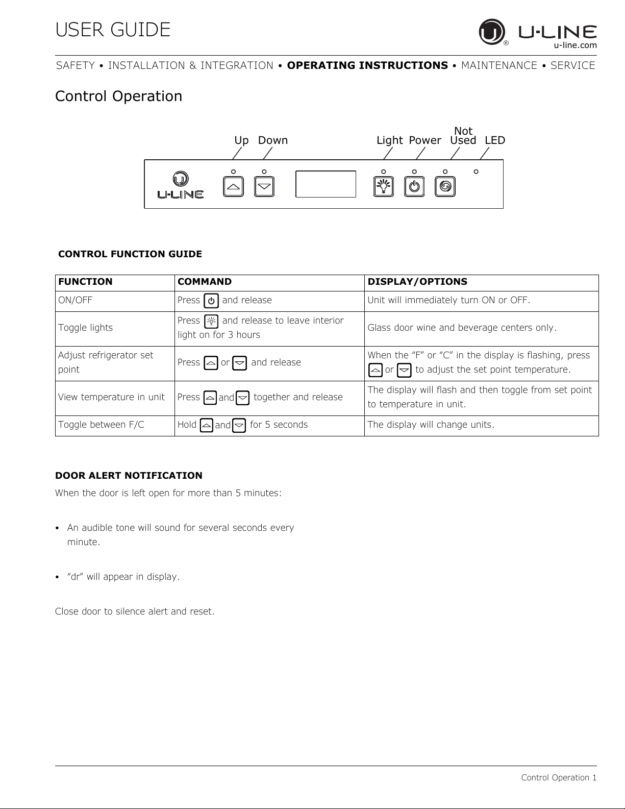
Control Operation
DOOR ALERT NOTIFICATION
When the door is left open for more than 5 minutes:
• An audible tone will sound for several seconds every
minute.
• “dr” will appear in display.
Close door to silence alert and reset.
Up Down Light Power
Not
Used LED
CONTROL FUNCTION GUIDE
FUNCTION COMMAND DISPLAY/OPTIONS
ON/OFF Press and release Unit will immediately turn ON or OFF.
Toggle lights
Press and release to leave interior
light on for 3 hours
Glass door wine and beverage centers only.
Adjust refrigerator set
point
Press and release
When the “F” or “C” in the display is flashing, press
to adjust the set point temperature.
View temperature in unit Press together and release
The display will flash and then toggle from set point
to temperature in unit.
Toggle between F/C Hold for 5 seconds The display will change units.
or
or
and
and
USER GUIDE
Sabbath Mode 1
u-line.com
SAFETY • INSTALLATION & INTEGRATION • OPERATING INSTRUCTIONS • MAINTENANCE • SERVICE
L
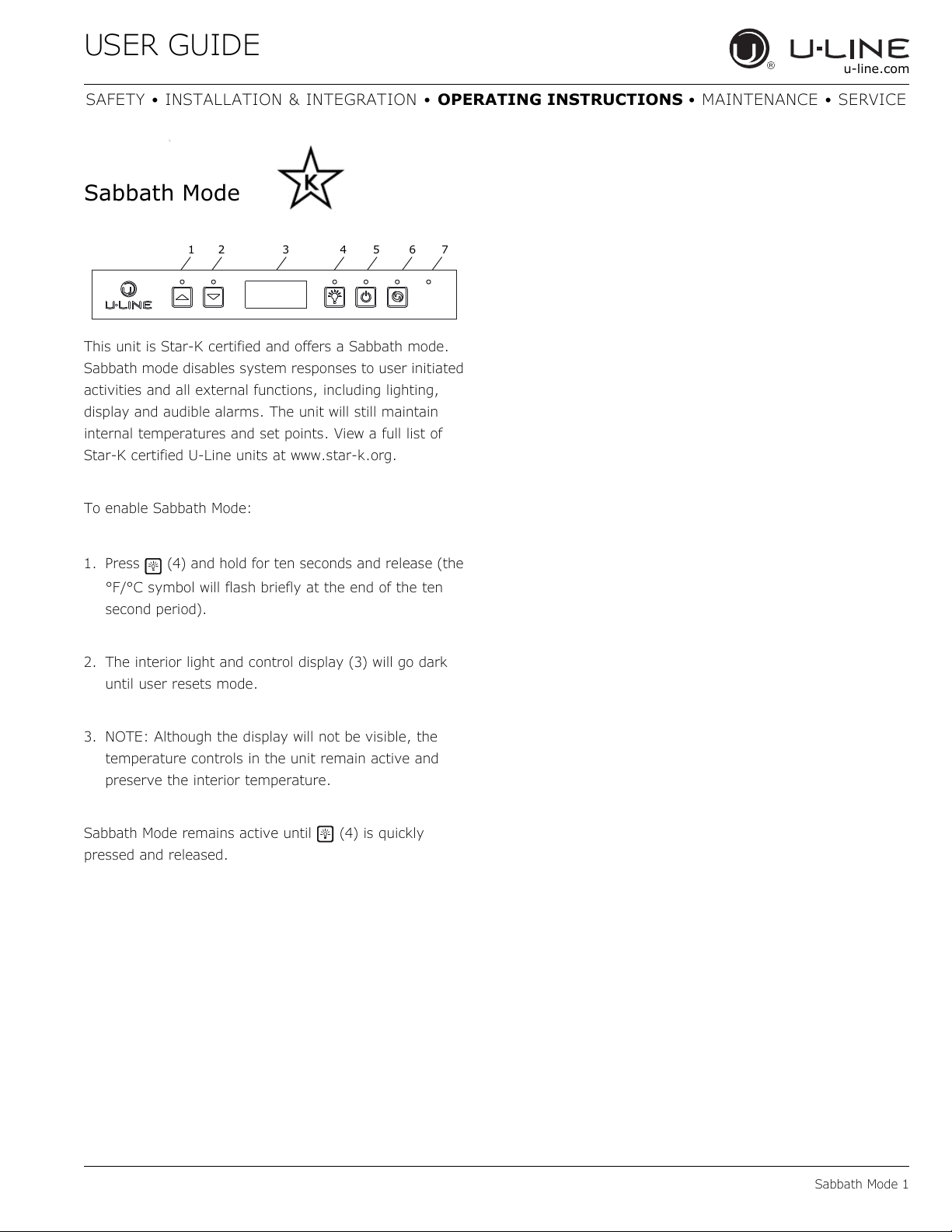
Sabbath Mode
This unit is Star-K certified and offers a Sabbath mode.
Sabbath mode disables system responses to user initiated
activities and all external functions, including lighting,
display and audible alarms. The unit will still maintain
internal temperatures and set points. View a full list of
Star-K certified U-Line units at www.star-k.org.
To enable Sabbath Mode:
1. Press (4) and hold for ten seconds and release (the
°F/°C symbol will flash briefly at the end of the ten
second period).
2. The interior light and control display (3) will go dark
until user resets mode.
3. NOTE: Although the display will not be visible, the
temperature controls in the unit remain active and
preserve the interior temperature.
Sabbath Mode remains active until (4) is quickly
pressed and released.
12 3456 7
USER GUIDE
Airflow and Product Loading 1
u-line.com
SAFETY • INSTALLATION & INTEGRATION • OPERATING INSTRUCTIONS • MAINTENANCE • SERVICE
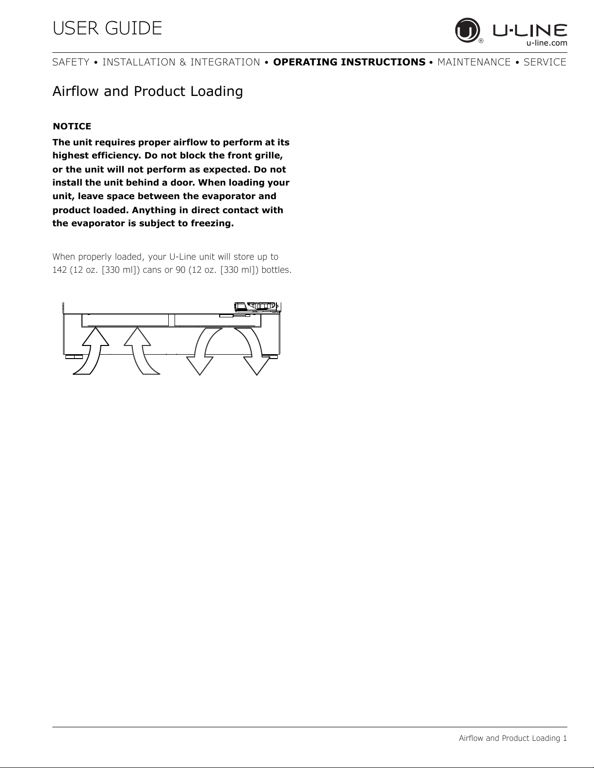
Airflow and Product Loading
NOTICE
The unit requires proper airflow to perform at its
highest efficiency. Do not block the front grille,
or the unit will not perform as expected. Do not
install the unit behind a door. When loading your
unit, leave space between the evaporator and
product loaded. Anything in direct contact with
the evaporator is subject to freezing.
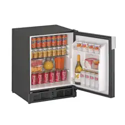
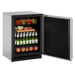
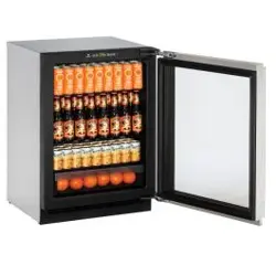
When properly loaded, your U-Line unit will store up to
142 (12 oz. [330 ml]) cans or 90 (12 oz. [330 ml]) bottles.
USER GUIDE
Cleaning 1
u-line.com
SAFETY • INSTALLATION & INTEGRATION • OPERATING INSTRUCTIONS • MAINTENANCE • SERVICE
Cleaning
EXTERIOR CLEANING
Stainless Models
Stainless door panels and handles can discolor when
exposed to chlorine gas, pool chemicals, saltwater or
cleaners with bleach.
Keep your stainless unit looking new by cleaning with a
good quality all-in-one stainless steel cleaner and polish
monthly. For best results use Claire
®
Stainless Steel
Polish and Cleaner. Comparable products are acceptable.
Frequent cleaning will remove surface contamination that
could lead to rust. Some installations may require cleaning
weekly.
Do not clean with steel wool pads.
Do not use stainless steel cleaners or polishes on
any glass surfaces.
Clean any glass surfaces with a non-chlorine glass
cleaner.
Do not use cleaners not specifically intended for
stainless steel on stainless steel surfaces (this
includes glass, tile and counter cleaners).
If any surface discoloring or rusting appears, clean it
quickly with Bon-Ami
®
or Barkeepers Friend Cleanser
®
and a nonabrasive cloth. Always clean with the grain.
Always finish with Claire
®
Stainless Steel Polish and
Cleaner or comparable product to prevent further
problems.
Using abrasive pads such as Scotchbrite™ will
cause the graining in the stainless steel to
become blurred.
Rust not cleaned up promptly can penetrate the
surface of the stainless steel and complete
removal of the rust may not be possible.
Integrated Models
To clean integrated panels, use household cleaner per the
cabinet manufacturer’s recommendation.
INTERIOR CLEANING
Disconnect power to the unit.
Clean the interior and all removed components using a
mild nonabrasive detergent and warm water solution
applied with a soft sponge or non-abrasive cloth.
Rinse the interior using a soft sponge and clean water.
Do not use any solvent-based or abrasive
cleaners. These types of cleaners may transfer taste to
the interior products and damage or discolor the lining.
DEFROSTING
Under normal conditions this unit does not require manual
defrosting. Minor frost on the rear wall or visible through
the evaporator plate vents is normal and will melt during
each off cycle.
If there is excessive build-up of 1/4" (6 mm) or more,
manually defrost the unit.
Ensure the door is closing and sealing properly.
High ambient temperature and excessive humidity can
also produce frost.
CAUTION
!
DO NOT use an ice pick or other sharp
instrument to help speed up defrosting. These
instruments can puncture the inner lining or
damage the cooling unit. DO NOT use any type of
heater to defrost. Using a heater to speed up
defrosting can cause personal injury and
damage to the inner lining.
USER GUIDE
Cleaning 2
u-line.com
SAFETY • INSTALLATION & INTEGRATION • OPERATING INSTRUCTIONS • MAINTENANCE • SERVICE
NOTICE
The drain pan was not designed to capture the
water created when manually defrosting. To
prevent water from overflowing the drain pan
and possibly damaging water sensitive flooring,
the unit must be removed from cabinetry.
To defrost:
1. Disconnect power to the unit.
2. Remove all products from the interior.
3. Prop the door in an open position (2 in. [50 mm]
minimum).
4. Allow the frost to melt naturally.
5. After the frost melts completely clean the interior and
all removed components. (See INTERIOR CLEANING).
6. When the interior is dry, reconnect power and turn unit
on.
USER GUIDE
Cleaning Condenser 1
u-line.com
SAFETY • INSTALLATION & INTEGRATION • OPERATING INSTRUCTIONS • MAINTENANCE • SERVICE
Cleaning Condenser
INTERVAL - EVERY SIX MONTHS
To maintain operational efficiency, keep the front grille
(plinth strip/base fascia) free of dust and lint, and clean
the condenser when necessary. Depending on
environmental conditions, more or less frequent cleaning
may be necessary.
WARNING
!
Disconnect electric current to the unit before
cleaning the condenser.
NOTICE
DO NOT use any type of cleaner on the
condenser unit. Condenser may be cleaned using
a vacuum, soft brush or compressed air.
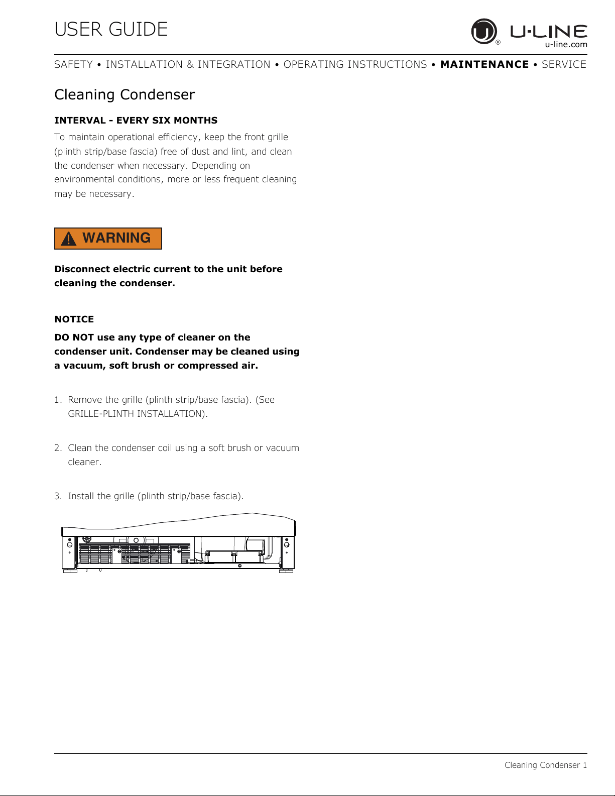
1. Remove the grille (plinth strip/base fascia). (See
GRILLE-PLINTH INSTALLATION).
2. Clean the condenser coil using a soft brush or vacuum
cleaner.
3. Install the grille (plinth strip/base fascia).
USER GUIDE
Extended Non-Use 1
u-line.com
SAFETY • INSTALLATION & INTEGRATION • OPERATING INSTRUCTIONS • MAINTENANCE • SERVICE
Extended Non-Use
VACATION/HOLIDAY, PROLONGED SHUTDOWN
The following steps are recommended for periods of
extended non-use:
1. Remove all consumable content from the unit.
2. Disconnect the power cord from its outlet/socket and
leave it disconnected until the unit is returned to
service.
3. If ice is on the evaporator, allow ice to thaw naturally.
4. Clean and dry the interior of the unit. Ensure all water
has been removed from the unit.
5. The door must remain open to prevent formation of
mold and mildew. Open door a minimum of 2"
(50 mm) to provide the necessary ventilation.
WINTERIZATION
If the unit will be exposed to temperatures of 40°F (5°C)
or less, the steps above must be followed.
For questions regarding winterization, please
call U-Line at +1.800.779.2547.
CAUTION
!
Damage caused by freezing temperatures is not
covered by the warranty.
USER GUIDE
Troubleshooting 1
u-line.com
SAFETY • INSTALLATION & INTEGRATION • OPERATING INSTRUCTIONS • MAINTENANCE • SERVICE
Troubleshooting
BEFORE CALLING FOR SERVICE
If you think your U-Line product is malfunctioning, read
the CONTROL OPERATION section to clearly understand
the function of the control.
If the problem persists, read the NORMAL OPERATING
SOUNDS and TROUBLESHOOTING GUIDE sections below
to help you quickly identify common problems and
possible causes and remedies. Most often, this will resolve
the problem without the need to call for service.
IF SERVICE IS REQUIRED
If you do not understand a troubleshooting remedy, or
your product needs service, contact U-Line Corporation
directly at +1.800.779.2547.
When you call, you will need your product Model and
Serial Numbers. This information appears on the Model
and Serial number plate located on the upper right or rear
wall of the interior of your product.
NORMAL OPERATING SOUNDS
All models incorporate rigid foam insulated cabinets to
provide high thermal efficiency and maximum sound
reduction for its internal working components. Despite this
technology, your model may make sounds that are
unfamiliar.
Normal operating sounds may be more noticeable because
of the unit’s environment. Hard surfaces such as cabinets,
wood, vinyl or tiled floors and paneled walls have a
tendency to reflect normal appliance operating noises.
Listed below are common refrigeration components with a
brief description of the normal operating sounds they
make. NOTE: Your product may not contain all the
components listed.
• Compressor: The compressor makes a hum or pulsing
sound that may be heard when it operates.
• Evaporator: Refrigerant flowing through an evaporator
may sound like boiling liquid.
• Condenser Fan: Air moving through a condenser may
be heard.
• Automatic Defrost Drain Pan: Water may be heard
dripping or running into the drain pan when the unit is
in the defrost cycle.
TROUBLESHOOTING GUIDE
DANGER
!
ELECTROCUTION HAZARD. Never attempt to
repair or perform maintenance on the unit
before disconnecting the main electrical power.
Troubleshooting - What to check when problems occur:
Problem Possible Cause and Remedy
Digital Display
and Light Do Not
Work.
Ensure power is connected to the unit.
If the unit is cooling, it may be in Sabbath
mode.
Interior Light
Does Not
Illuminate.
The light bulb may be defective.
If the unit is cooling, it may be in Sabbath
mode.
Light Remains on
When Door Is
Closed.
For glass door models, press the light icon
and close the door.
Check reed switch.
Unit Develops
Frost on Internal
Surfaces.
Frost on the rear wall is normal and will melt
during each off cycle.
If there is excessive build-up of 1/4" or
more, manually defrost the unit.
Ensure the door is closing and sealing
properly.
High ambient temperature and excessive
humidity can also produce frost.
Unit Develops
Condensation on
External
Surfaces.
The unit is exposed to excessive humidity.
Moisture will dissipate as humidity levels
decrease.
Digital Display
Functions, But
Unit Does Not
Cool.
Ensure the unit is not in “Showroom Mode.”
Momentarily unplug or interrupt power
supply to the unit.
Digital Display
Shows ER or E
Followed by a
Number.
E3 indicates the door may be opened too
long. Ensure the door is closing properly.
For other error codes contact U-Line
Customer Service.
USER GUIDE
Troubleshooting 2
u-line.com
SAFETY • INSTALLATION & INTEGRATION • OPERATING INSTRUCTIONS • MAINTENANCE • SERVICE
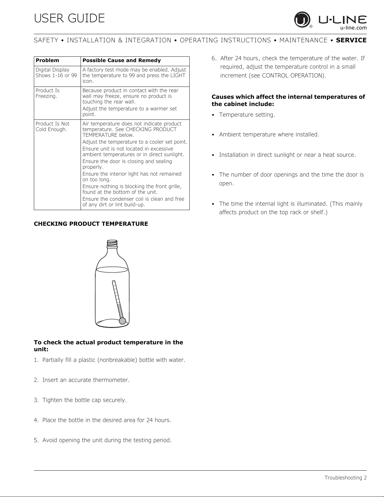
CHECKING PRODUCT TEMPERATURE
To check the actual product temperature in the
unit:
1. Partially fill a plastic (nonbreakable) bottle with water.
2. Insert an accurate thermometer.
3. Tighten the bottle cap securely.
4. Place the bottle in the desired area for 24 hours.
5. Avoid opening the unit during the testing period.
6. After 24 hours, check the temperature of the water. If
required, adjust the temperature control in a small
increment (see CONTROL OPERATION).
Causes which affect the internal temperatures of
the cabinet include:
• Temperature setting.
• Ambient temperature where installed.
• Installation in direct sunlight or near a heat source.
• The number of door openings and the time the door is
open.
• The time the internal light is illuminated. (This mainly
affects product on the top rack or shelf.)
Digital Display
Shows 1-16 or 99
A factory test mode may be enabled. Adjust
the temperature to 99 and press the LIGHT
icon.
Product Is
Freezing.
Because product in contact with the rear
wall may freeze, ensure no product is
touching the rear wall.
Adjust the temperature to a warmer set
point.
Product Is Not
Cold Enough.
Air temperature does not indicate product
temperature. See CHECKING PRODUCT
TEMPERATURE below.
Adjust the temperature to a cooler set point.
Ensure unit is not located in excessive
ambient temperatures or in direct sunlight.
Ensure the door is closing and sealing
properly.
Ensure the interior light has not remained
on too long.
Ensure nothing is blocking the front grille,
found at the bottom of the unit.
Ensure the condenser coil is clean and free
of any dirt or lint build-up.
Problem Possible Cause and Remedy
USER GUIDE
u-line.com
SAFETY • INSTALLATION & INTEGRATION • OPERATING INSTRUCTIONS • MAINTENANCE • SERVICE
U-Line Corporation (U-Line) Limited Warranty
One Year Limited Warranty
For one year from the date of original purchase, this U-Line product warranty covers all parts and labor to repair or replace any part of the
product that proves to be defective in materials or workmanship. For products installed and used for normal residential use, material
cosmetic defects are included in this warranty, with coverage limited to 60 days from the date of original purchase. All service provided by U-
Line under the above warranty must be performed by U-Line factory authorized service, unless otherwise specified by U-Line. Service
provided during normal business hours.
Available Second Year Limited Warranty
Beyond the standard one year warranty outlined above, U-Line offers an extension of the one year warranty coverage for an additional
second year from the date of purchase, free of charge. To take advantage of this second year warranty, you must register your product with
U-Line within two months from the date of purchase at u-line.com providing proof of purchase.
Five Year Sealed System Limited Warranty
For five years from the date of original purchase, U-Line will repair or replace the following parts, labor not included, that prove to be
defective in materials or workmanship: compressor, condenser, evaporator, drier, and all connecting tubing. All service provided by U-Line
under the above warranty must be performed by U-Line factory authorized service, unless otherwise specified by U-Line. Service provided
during normal business hours.
Terms
These warranties apply only to products installed in any one of the fifty states of the United States, the District of Columbia, or the ten
provinces of Canada. The warranties do not cover any parts or labor to correct any defect caused by negligence, accident or improper use,
maintenance, installation, service, repair, acts of God, fire, flood or other natural disasters. The product must be installed, operated, and
maintained in accordance with the U-Line User Guide.
The remedies described above for each warranty are the only ones that U-Line will provide, either under these warranties or under any
warranty arising by operation of law. U-Line will not be responsible for any consequential or incidental damages arising from the breach of
these warranties or any other warranty, whether express, implied, or statutory. Some states do not allow the exclusion or limitation of
incidental or consequential damages, so the above limitation or exclusion may not apply to you. These warranties give you specific legal
rights, and you may also have other rights which vary from state to state.
Any warranty that may be implied in connection with your purchase or use of the product, including any warranty of merchantability or any
warranty fit for a particular purpose is limited to the duration of these warranties, and only extends to five years in duration for the parts
described in the section related to the five year limited warranty above. Some states do not allow limitations on how long an implied warranty
lasts, so the above limitations may not apply to you.
• The warranties only apply to the original purchaser and are non-transferable.
• The second year and five year warranties cover products installed and used for normal residential or designated marine use only.
• The warranties apply to units operated outside only if designed for outdoor use by model and serial number.
• Replacement water filters, light bulbs, and other consumable parts are not covered by these warranties.
• The start of U-Line’s obligation is limited to four years after the shipment date from U-Line.
• In-home instruction on how to use your product is not covered by these warranties.
• Food, beverage, and medicine loss are not covered by these warranties.
• If the product is located in an area where U-Line factory authorized service is not available, you may be responsible for a trip charge
or you may be required to bring the product to a U-Line factory authorized service location at your own cost and expense.
• Units purchased after use as floor displays are covered by the limited one year warranty only and no coverage is provided for cosmetic
defects.
• Signal issues related to Wi-Fi connectivity are not covered by these warranties.
For parts and service assistance, or to find U-Line factory authorized service near you, contact U-Line:
8900 N. 55th Street, Milwaukee, WI 53223 • u-line.com • onlineservice@u-line.com • +1.800.779.2547
Copyright © 2014/2017 U-Line Corporation. All Rights Reserved. | Publication Number 30379 | 04/2017 Rev. K
Warranty 1
USER GUIDE
Wire Diagram 1
u-line.com
SAFETY • INSTALLATION & INTEGRATION • OPERATING INSTRUCTIONS • MAINTENANCE • SERVICE
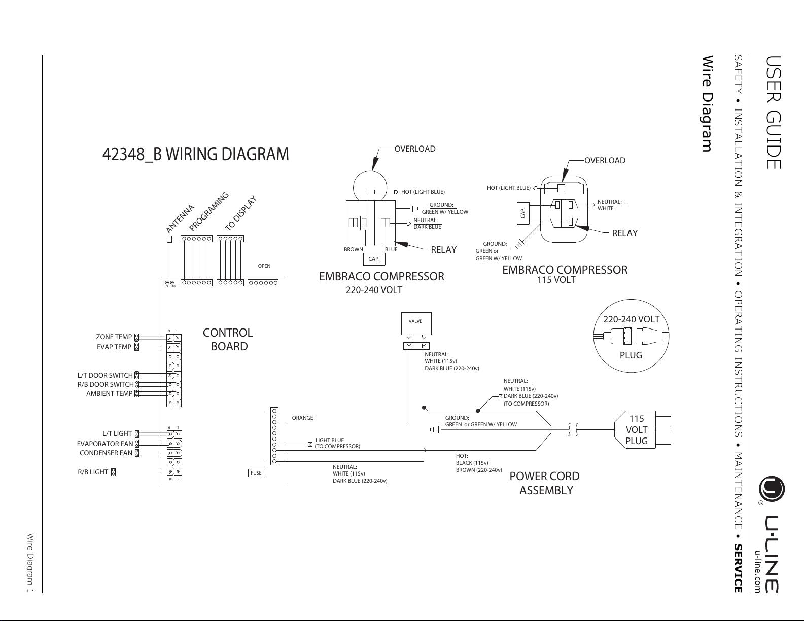
Wire Diagram
42348_B WIRING DIAGRAM
POWER CORD
ASSEMBLY
GROUND:
GREEN or GREEN W/ YELLOW
HOT:
BLACK (115v)
BROWN (220-240v)
NEUTRAL:
LIGHT BLUE
(TO COMPRESSOR)
1
10
NEUTRAL:
WHITE
HOT (LIGHT BLUE)
RELAY
EMBRACO COMPRESSOR
GREEN or
GREEN W/ YELLOW
GROUND:
115
VOLT
PLUG
220-240 VOLT
PLUG
OVERLOAD
NEUTRAL:
WHITE (115v)
DARK BLUE (220-240v)
(TO COMPRESSOR)
WHITE (115v)
DARK BLUE (220-240v)
VALVE
ORANGE
NEUTRAL:
WHITE (115v)
DARK BLUE (220-240v)
CONTROL
BOARD
ZONE TEMP
9
1
EVAP TEMP
L/T DOOR SWITCH
AMBIENT TEMP
R/B DOOR SWITCH
FUSE
6
1
10
5
R/B LIGHT
L/T LIGHT
CONDENSER FAN
EVAPORATOR FAN
PROGRAMING
TO DISPLAY
OPEN
ANTENNA
J9
J10
115 VOLT
HOT (LIGHT BLUE)
OVERLOAD
EMBRACO COMPRESSOR
220-240 VOLT
RELAY
GREEN W/ YELLOW
GROUND:
NEUTRAL:
DARK BLUE
CAP.
CAP.
BROWN BLUE
USER GUIDE
Product Liability 1
u-line.com
SAFETY • INSTALLATION & INTEGRATION • OPERATING INSTRUCTIONS • MAINTENANCE • SERVICE
Product Liability
Field service technicians are authorized to make an initial
assessment in the event of reported damages. If there are
any questions about the process involved, the technician
should call U-Line for further explanation.
While inspecting for defects or installation issues, photos
should be taken to document any damages or issues
found.
During the assessment, if the service technician is able to
find the source of the damage and it can be resolved by
replacement of a part, the servicer is authorized to
replace the part in question. The part that caused the
damage must be returned to U-Line in its entirety. The
part must be clearly labeled with the serial number of the
unit it was removed from, the date, and the servicer who
removed the part.
If the service technician determines the damage is the
result of installation issues (water connection/drain, etc.),
the consumer would be notified and the issues shall be
resolved at the direction of the consumer.
If damage is evident and the service technician is unable
to find the source, U-Line must be contacted at 1-800-
799-2547 for further direction
8900 N. 55th Street • Milwaukee, WI 53223
T: +1.414.354.0300 • F: +1.414.354.354.5696
Website:
www.u-line.com
Right product. Right place.
Right temperature Since 1962.
USER GUIDE
Warranty Claims 1
u-line.com
SAFETY • INSTALLATION & INTEGRATION • OPERATING INSTRUCTIONS • MAINTENANCE • SERVICE
Warranty Claims
The following information defines the parameters for filing
a warranty claim:
• Valid serial number needed
• Valid model number needed
• Narda (or equivalent) form or submitted online at
www.u-line.com
• 60 day submittal deadline from date of completed
service
• Only one repair or unit per warranty claim
• Refrigerant should be labeled and included on the labor
submittal
• Door and water level adjustments are covered 30 days
from install date.
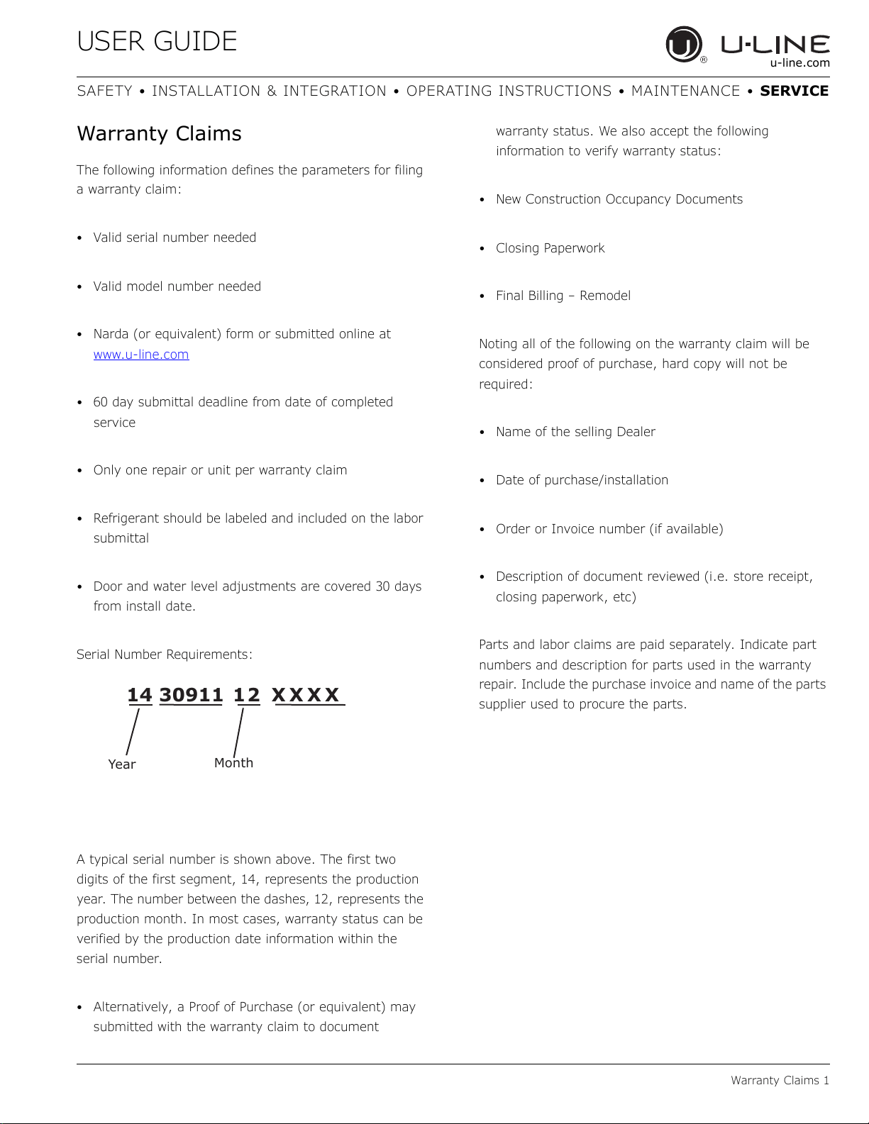
Serial Number Requirements:
A typical serial number is shown above. The first two
digits of the first segment, 14, represents the production
year. The number between the dashes, 12, represents the
production month. In most cases, warranty status can be
verified by the production date information within the
serial number.
• Alternatively, a Proof of Purchase (or equivalent) may
submitted with the warranty claim to document
warranty status. We also accept the following
information to verify warranty status:
• New Construction Occupancy Documents
•Closing Paperwork
• Final Billing – Remodel
Noting all of the following on the warranty claim will be
considered proof of purchase, hard copy will not be
required:
• Name of the selling Dealer
• Date of purchase/installation
• Order or Invoice number (if available)
• Description of document reviewed (i.e. store receipt,
closing paperwork, etc)
Parts and labor claims are paid separately. Indicate part
numbers and description for parts used in the warranty
repair. Include the purchase invoice and name of the parts
supplier used to procure the parts.
14 30911 12 XXXX
Year
Month
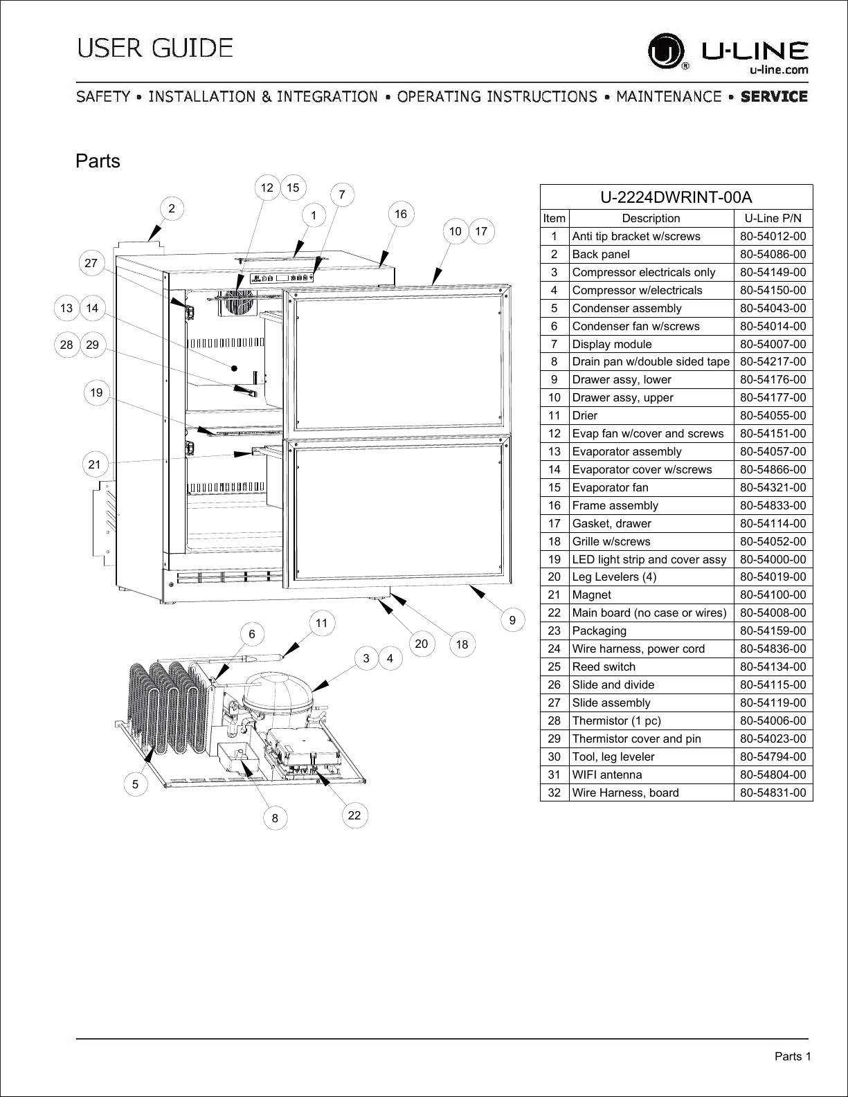
U-2224DWRINT-00A
Item Description U-Line P/N
1 Anti tip bracket w/screws 80-54012-00
2 Back panel 80-54086-00
3 Compressor electricals only 80-54149-00
4 Compressor w/electricals 80-54150-00
5 Condenser assembly 80-54043-00
6 Condenser fan w/screws 80-54014-00
7 Display module 80-54007-00
8 Drain pan w/double sided tape 80-54217-00
9 Drawer assy, lower 80-54176-00
10 Drawer assy, upper 80-54177-00
11 Drier 80-54055-00
12 Evap fan w/cover and screws 80-54151-00
13 Evaporator assembly 80-54057-00
14 Evaporator cover w/screws 80-54866-00
15 Evaporator fan 80-54321-00
16 Frame assembly 80-54833-00
17 Gasket, drawer 80-54114-00
18 Grille w/screws 80-54052-00
19 LED light strip and cover assy 80-54000-00
20 Leg Levelers (4) 80-54019-00
21 Magnet 80-54100-00
22 Main board (no case or wires) 80-54008-00
23 Packaging 80-54159-00
24 Wire harness, power cord 80-54836-00
25 Reed switch 80-54134-00
26 Slide and divide 80-54115-00
27 Slide assembly 80-54119-00
28 Thermistor (1 pc) 80-54006-00
29 Thermistor cover and pin 80-54023-00
30 Tool, leg leveler 80-54794-00
31 WIFI antenna 80-54804-00
32 Wire Harness, board 80-54831-00
Parts
Parts 1
1
2
3 4
5
6
7
8
9
10 17
11
13 14
20
16
27
18
22
21
19
28 29
12 15
USER GUIDE
Ordering Replacement Parts 1
u-line.com
SAFETY • INSTALLATION & INTEGRATION • OPERATING INSTRUCTIONS • MAINTENANCE • SERVICE
Ordering Replacement Parts
If you have a purchasing account, please utilize our
service website to order parts.
Orders may also be placed by Fax or phone. See our
contact information below:
www.U-LineService.com (with service login)
FAX Number: +1.414.354.5696
Phone Number: +1.800.779.2547
NOTICE
Use only genuine U-Line replacement parts. The
use of non-U-Line parts can reduce speed of ice
production, cause water to overflow from ice
maker mold, damage the unit, and void the
warranty.
Warranty parts will be shipped at no charge after U-Line
confirms warranty status. Please provide the model, serial
number, part number and part description. Some parts
will require color or voltage information.
If U-Line requires the return of original parts, we will
inform you when the parts order is taken. This
requirement will be noted on your packing list. A prepaid
shipping label will be included with the replacement part.
Please enclose a copy of the parts packing list and any
labor claims with your return. Please be sure the model
and serial numbers are legible on the paperwork. Tag the
part with the reported defect.
When ordering a non-warranty part, you will need an open
account and tax exemption on file at U-Line. Another
option would be to visit www.u-line.com to locate an
authorized parts distributor in your area.
USER GUIDE
System Diagnosis Guide 1
u-line.com
SAFETY • I NSTALLATION & INTEGRATION • OPERATING I NSTRUCTIONS • MAI NTENANCE • SERVI CE
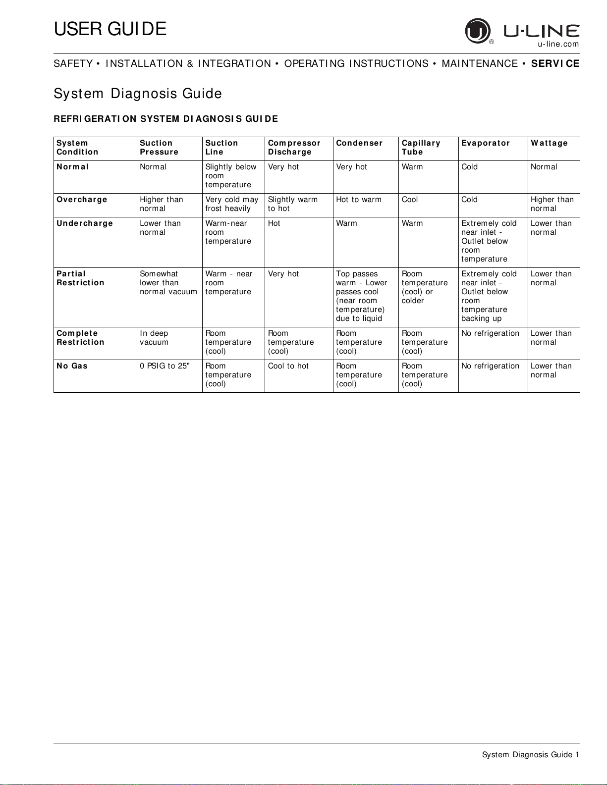
Syst em Diagnosis Guide
REFRI GERATI ON SYSTEM DI AGN OSI S GUI DE
Syst e m
Condition
Suct ion
Pre ssur e
Suct ion
Lin e
Com pr e ssor
Discha rge
Condense r Capillar y
Tube
Eva por at or W at tage
N orm al Normal Slightly below
room
temperature
Very hot Very hot Warm Cold Normal
Over char ge Higher than
normal
Very cold may
frost heavily
Slightly warm
to hot
Hot to warm Cool Cold Higher than
normal
Unde r cha r ge Lower than
normal
Warm-near
room
temperature
Hot Warm Warm Extremely cold
near inlet -
Outlet below
room
temperature
Lower than
normal
Part ia l
Re st r iction
Somewhat
lower than
normal vacuum
Warm - near
room
temperature
Very hot Top passes
warm - Lower
passes cool
(near room
temperature)
due to liquid
Room
temperature
(cool) or
colder
Extremely cold
near inlet -
Outlet below
room
temperature
backing up
Lower than
normal
Com plet e
Re st r iction
In deep
vacuum
Room
temperature
(cool)
Room
temperature
(cool)
Room
temperature
(cool)
Room
temperature
(cool)
No refrigeration Lower than
normal
N o Ga s 0 PSIG to 25" Room
temperature
(cool)
Cool to hot Room
temperature
(cool)
Room
temperature
(cool)
No refrigeration Lower than
normal
USER GUIDE
Compressor Specifications 1
u-line.com
SAFETY • INSTALLATION & INTEGRATION • OPERATING INSTRUCTIONS • MAINTENANCE • SERVICE
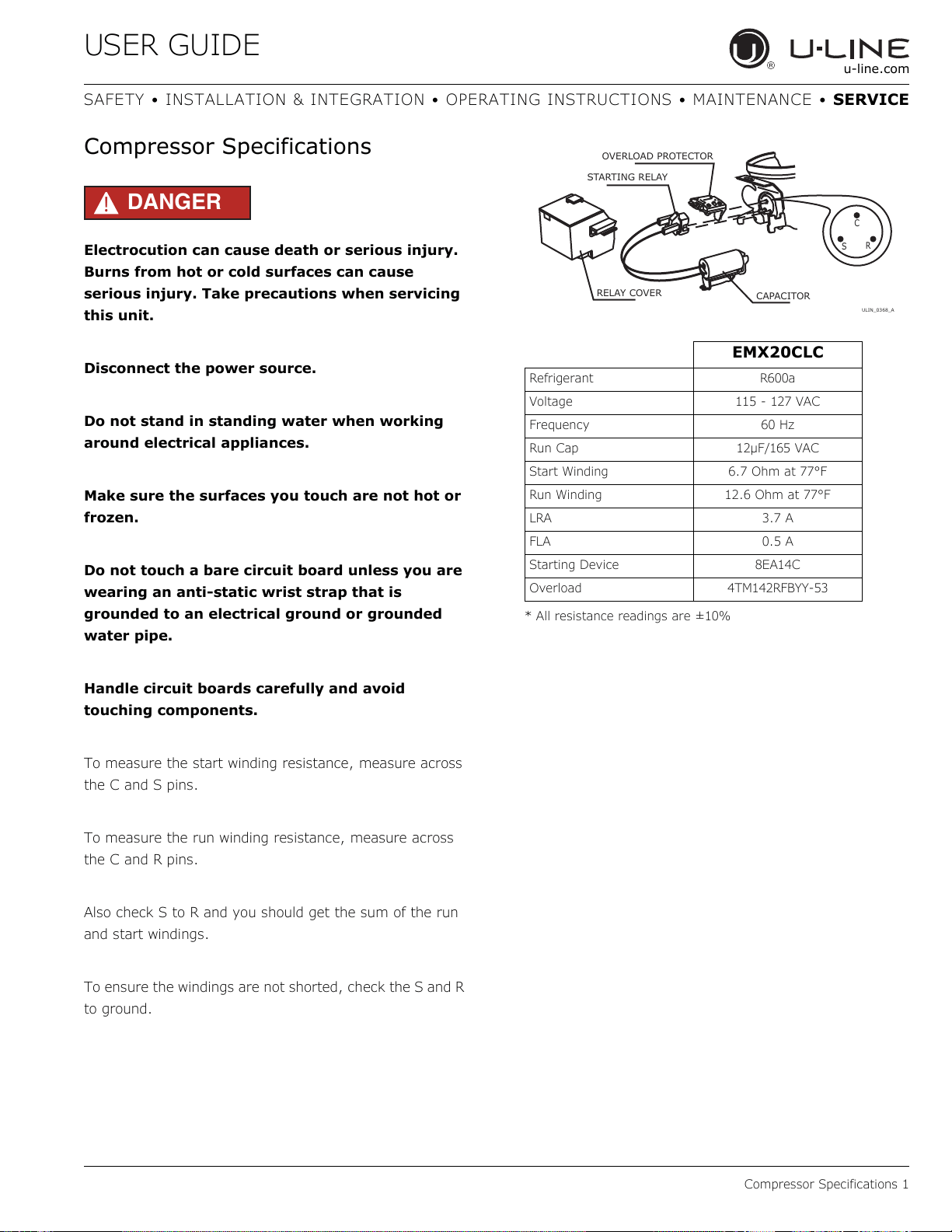
Compressor Specifications
DANGER
!
Electrocution can cause death or serious injury.
Burns from hot or cold surfaces can cause
serious injury. Take precautions when servicing
this unit.
Disconnect the power source.
Do not stand in standing water when working
around electrical appliances.
Make sure the surfaces you touch are not hot or
frozen.
Do not touch a bare circuit board unless you are
wearing an anti-static wrist strap that is
grounded to an electrical ground or grounded
water pipe.
Handle circuit boards carefully and avoid
touching components.
To measure the start winding resistance, measure across
the C and S pins.
To measure the run winding resistance, measure across
the C and R pins.
Also check S to R and you should get the sum of the run
and start windings.
To ensure the windings are not shorted, check the S and R
to ground.
* All resistance readings are ±10%
EMX20CLC
Refrigerant R600a
Voltage 115 - 127 VAC
Frequency 60 Hz
Run Cap 12μF/165 VAC
Start Winding 6.7 Ohm at 77°F
Run Winding 12.6 Ohm at 77°F
LRA 3.7 A
FLA 0.5 A
Starting Device 8EA14C
Overload 4TM142RFBYY-53
C
S
R
OVERLOAD PROTECTOR
STARTING RELAY
CAPACITOR
RELAY COVER
ULIN_0368_A
USER GUIDE
Troubleshooting - Extended 1
u-line.com
SAFETY • INSTALLATION & INTEGRATION • OPERATING INSTRUCTIONS • MAINTENANCE • SERVICE
Troubleshooting - Extended
CAUTION
!
Never attempt to repair or perform maintenance
on the unit until the main electrical power has
been disconnected from the unit.
SPECIFIC ERRORS AND ISSUES
The technically advanced diagnostic capabilities of the
electronic controls utilized on the 1200 and 2200 series
units allows for easy and thorough troubleshooting.
Navigation of the control is the key and is explained in the
CONTROL OPERATION section of the manual, along with
control button layout, control function descriptions, a
service mode menu and service menu selection
explanations.
Verification of temperature and thermistor performance
can be identified by directly viewing thermistor readings in
the service mode.
Component failure issues can be identified through service
mode menu #19, “Component Testing.” Individual
components can be switched on and off to check for both
proper function of a specific component and also delivery
of supply voltage to the components through the relays
and DC outputs located on the relay/power board.
Included in this section are some diagnostic tips and of
course, if additional help is required please contact the
U-Line Corp, “Customer Care Facility” at +1.800.779.2547
for assistance.
NORMAL OPERATING SOUNDS
All models incorporate rigid foam insulated cabinets to
provide high thermal efficiency and maximum sound
reduction for its internal working components. Despite this
technology, your model may make sounds that are
unfamiliar.
Normal operating sounds may be more noticeable because
of the unit’s environment. Hard surfaces such as cabinets,
wood, vinyl or tiled floors and paneled walls have a
tendency to reflect normal appliance operating noises.
Listed below are common refrigeration components with a
brief description of the normal operating sounds they
make. NOTE: Your product may not contain all the
components listed.
• Compressor: The compressor makes a hum or pulsing
sound that may be heard when it operates.
• Evaporator: Refrigerant flowing through an evaporator
may sound like boiling liquid.
• Condenser Fan: Air moving through a condenser may
be heard.
• Automatic Defrost Drain Pan: Water may be heard
dripping or running into the drain pan when the unit is
in the defrost cycle.
Solenoid Valves: An occasional clicking sound may be
heard as solenoid valves are operated.
USER GUIDE
Troubleshooting - Extended 2
u-line.com
SAFETY • INSTALLATION & INTEGRATION • OPERATING INSTRUCTIONS • MAINTENANCE • SERVICE
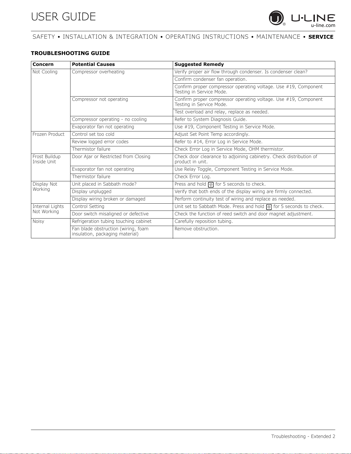
TROUBLESHOOTING GUIDE
Concern Potential Causes Suggested Remedy
Not Cooling Compressor overheating Verify proper air flow through condenser. Is condenser clean?
Confirm condenser fan operation.
Confirm proper compressor operating voltage. Use #19, Component
Testing in Service Mode.
Compressor not operating Confirm proper compressor operating voltage. Use #19, Component
Testing in Service Mode.
Test overload and relay, replace as needed.
Compressor operating - no cooling Refer to System Diagnosis Guide.
Evaporator fan not operating Use #19, Component Testing in Service Mode.
Frozen Product Control set too cold Adjust Set Point Temp accordingly.
Review logged error codes Refer to #14, Error Log in Service Mode.
Thermistor failure Check Error Log in Service Mode, OHM thermistor.
Frost Buildup
Inside Unit
Door Ajar or Restricted from Closing Check door clearance to adjoining cabinetry. Check distribution of
product in unit.
Evaporator fan not operating Use Relay Toggle, Component Testing in Service Mode.
Thermistor failure Check Error Log.
Display Not
Working
Unit placed in Sabbath mode? Press and hold for 5 seconds to check.
Display unplugged Verify that both ends of the display wiring are firmly connected.
Display wiring broken or damaged Perform continuity test of wiring and replace as needed.
Internal Lights
Not Working
Control Setting Unit set to Sabbath Mode. Press and hold for 5 seconds to check.
Door switch misaligned or defective Check the function of reed switch and door magnet adjustment.
Noisy Refrigeration tubing touching cabinet Carefully reposition tubing.
Fan blade obstruction (wiring, foam
insulation, packaging material)
Remove obstruction.
USER GUIDE
Troubleshooting - Extended 3
u-line.com
SAFETY • INSTALLATION & INTEGRATION • OPERATING INSTRUCTIONS • MAINTENANCE • SERVICE
MAIN CONTROL
The main control board is very robust and is rarely the
cause of system issues. It is important to fully diagnose
the board for any suspected failures before attempting to
remove the board for replacement or service. Follow the
guidelines below to fully test and diagnose the main
control.
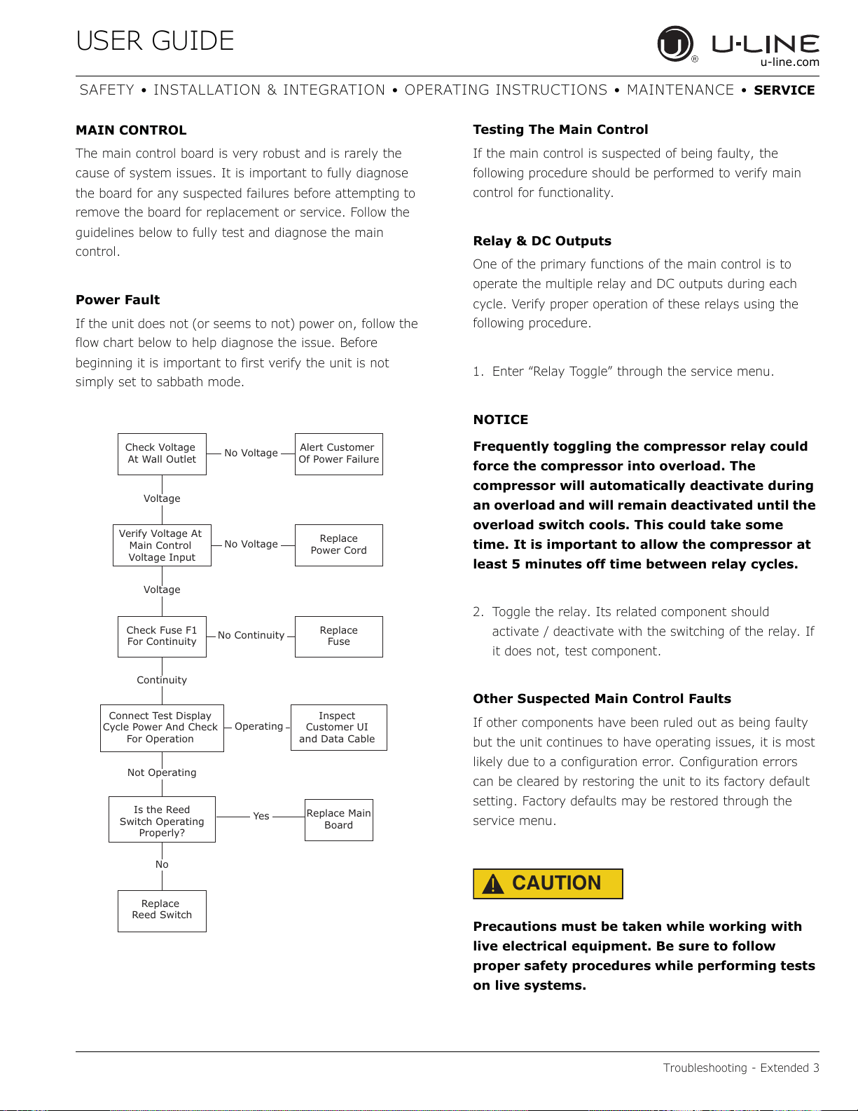
Power Fault
If the unit does not (or seems to not) power on, follow the
flow chart below to help diagnose the issue. Before
beginning it is important to first verify the unit is not
simply set to sabbath mode.
Testing The Main Control
If the main control is suspected of being faulty, the
following procedure should be performed to verify main
control for functionality.
Relay & DC Outputs
One of the primary functions of the main control is to
operate the multiple relay and DC outputs during each
cycle. Verify proper operation of these relays using the
following procedure.
1. Enter “Relay Toggle” through the service menu.
NOTICE
Frequently toggling the compressor relay could
force the compressor into overload. The
compressor will automatically deactivate during
an overload and will remain deactivated until the
overload switch cools. This could take some
time. It is important to allow the compressor at
least 5 minutes off time between relay cycles.
2. Toggle the relay. Its related component should
activate / deactivate with the switching of the relay. If
it does not, test component.
Other Suspected Main Control Faults
If other components have been ruled out as being faulty
but the unit continues to have operating issues, it is most
likely due to a configuration error. Configuration errors
can be cleared by restoring the unit to its factory default
setting. Factory defaults may be restored through the
service menu.
CAUTION
!
Precautions must be taken while working with
live electrical equipment. Be sure to follow
proper safety procedures while performing tests
on live systems.
Check Voltage
At Wall Outlet
Verify Voltage At
Main Control
Voltage Input
Check Fuse F1
For Continuity
Replace
Reed Switch
Replace Main
Board
Replace
Fuse
Replace
Power Cord
Alert Customer
Of Power Failure
Is the Reed
Switch Operating
Properly?
Inspect
Customer UI
and Data Cable
Connect Test Display
Cycle Power And Check
For Operation
No Voltage
No Voltage
Voltage
Continuity
Operating
Not Operating
No Continuity
No
Yes
Voltage
USER GUIDE
Troubleshooting - Extended 4
u-line.com
SAFETY • INSTALLATION & INTEGRATION • OPERATING INSTRUCTIONS • MAINTENANCE • SERVICE
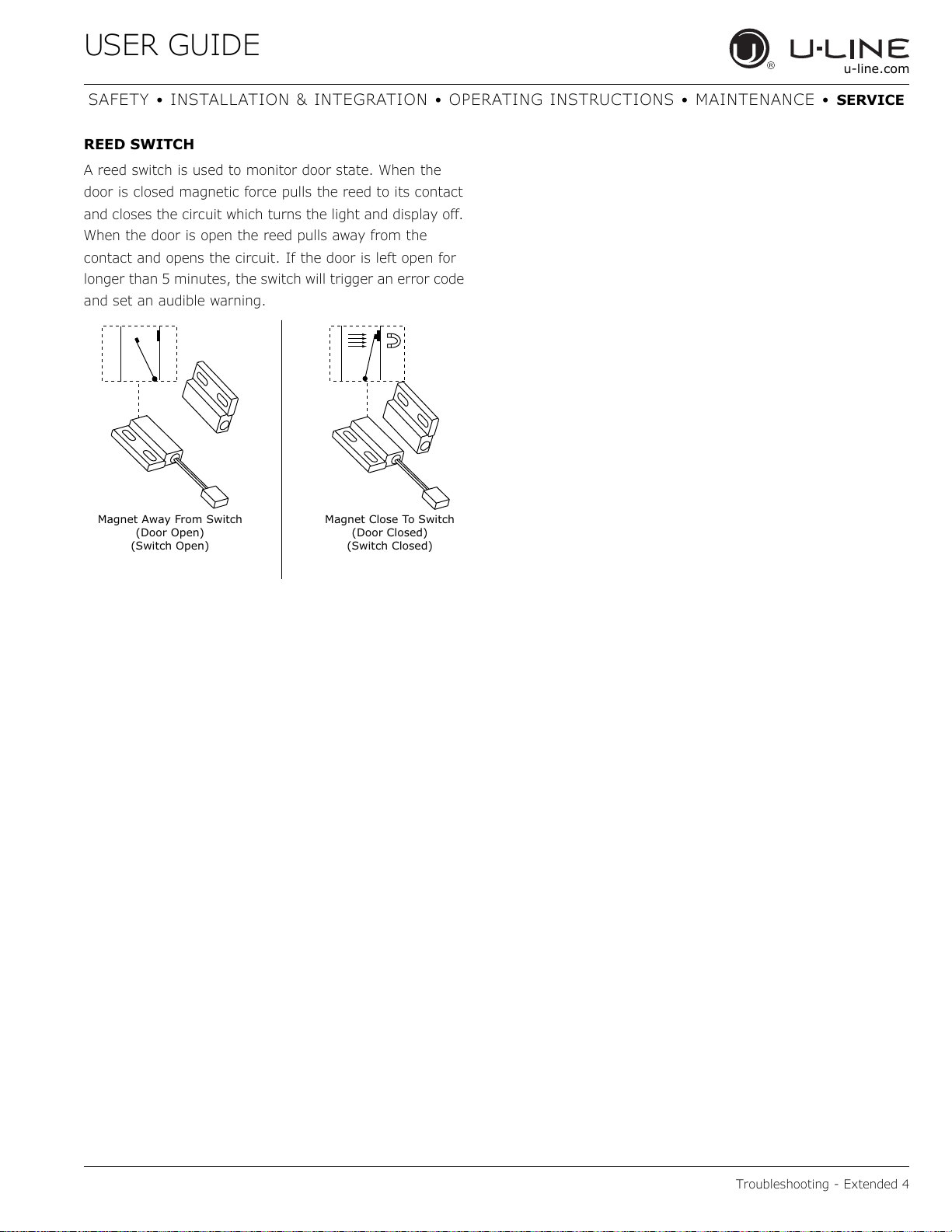
REED SWITCH
A reed switch is used to monitor door state. When the
door is closed magnetic force pulls the reed to its contact
and closes the circuit which turns the light and display off.
When the door is open the reed pulls away from the
contact and opens the circuit. If the door is left open for
longer than 5 minutes, the switch will trigger an error code
and set an audible warning.
Magnet Close To Switch
(Door Closed)
(Switch Closed)
Magnet Away From Switch
(Door Open)
(Switch Open)
USER GUIDE
Control Operation - Service 1
u-line.com
SAFETY • INSTALLATION & INTEGRATION • OPERATI NG INSTRUCTIONS • MAI NTENANCE • SERV I CE
Control Operation - Service
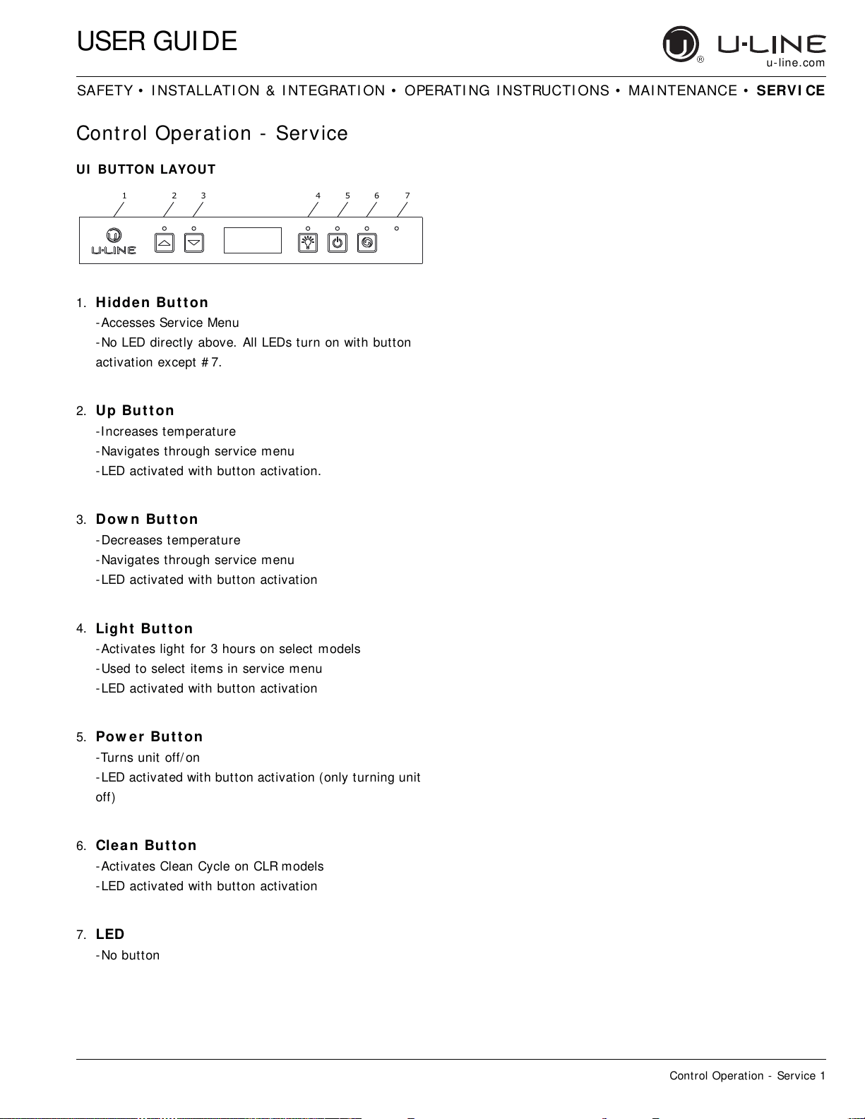
UI BUTTON LAYOUT
1. Hidde n Bu t t on
-Accesses Service Menu
-No LED directly above. All LEDs turn on with button
activation except # 7.
2.
Up But t on
-Increases temperature
-Navigates through service menu
-LED activated with button activation.
3.
Dow n But t on
-Decreases temperature
-Navigates through service menu
-LED activated with button activation
4.
Light But t on
-Activates light for 3 hours on select models
-Used to select items in service menu
-LED activated with button activation
5.
Pow e r But t on
-Turns unit off/ on
-LED activated with button activation (only turning unit
off)
6. Clea n But t on
-Activates Clean Cycle on CLR models
-LED activated with button activation
7. LED
-No button
123 4567
USER GUIDE
Control Operation - Service 2
u-line.com
SAFETY • INSTALLATION & INTEGRATION • OPERATI NG INSTRUCTIONS • MAI NTENANCE • SERV I CE
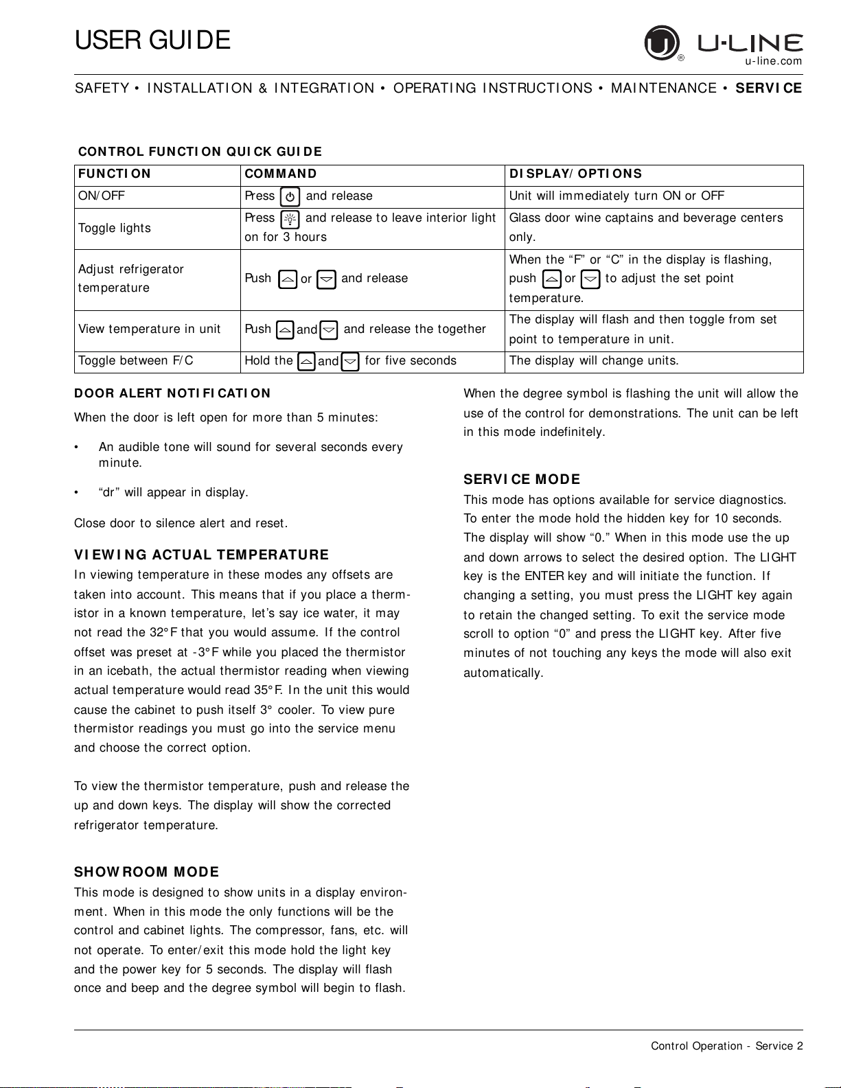
DOOR ALERT N OTI FI CATI ON
When the door is left open for more than 5 minutes:
• An audible tone will sound for several seconds every
minute.
• “dr” will appear in display.
Close door to silence alert and reset.
VI EW I NG ACTUAL TEM PERATURE
In viewing temperature in these modes any offsets are
taken into account. This means that if you place a therm-
istor in a known temperature, let ’s say ice water, it may
not read the 32° F that you would assume. If the control
offset was preset at - 3° F while you placed the thermistor
in an icebath, the actual thermistor reading when viewing
actual temperature would read 35° F. In the unit this would
cause the cabinet to push itself 3° cooler. To view pure
thermistor readings you must go into the service menu
and choose the correct option.
To view the thermistor temperature, push and release the
up and down keys. The display will show the corrected
refrigerator temperature.
SH OW ROOM MOD E
This mode is designed to show units in a display environ-
ment. When in this mode the only functions will be the
control and cabinet lights. The compressor, fans, etc. will
not operate. To enter/ exit this mode hold the light key
and the power key for 5 seconds. The display will flash
once and beep and the degree symbol will begin to flash.
When the degree symbol is flashing the unit will allow the
use of the control for demonstrations. The unit can be left
in this mode indefinitely.
SERVI CE MOD E
This mode has options available for service diagnostics.
To enter the mode hold the hidden key for 10 seconds.
The display will show “0.” When in this mode use the up
and down arrows to select the desired option. The LIGHT
key is the ENTER key and will initiate the function. If
changing a setting, you must press the LIGHT key again
to retain the changed setting. To exit the service mode
scroll to option “0” and press the LIGHT key. After five
minutes of not touching any keys the mode will also exit
automatically.
CON TROL FUN CTI ON QUI CK GUI D E
FUN CTI ON COMM AN D DI SPLAY/ OPTI ON S
ON/ OFF Press and release Unit will immediately turn ON or OFF
Toggle lights
Press and release to leave interior light
on for 3 hours
Glass door wine captains and beverage centers
only.
Adjust refrigerator
temperature
Push and release
When the “F” or “C” in the display is flashing,
push to adjust the set point
temperature.
View temperature in unit Push and release the together
The display will flash and then toggle from set
point to temperature in unit.
Toggle between F/ C Hold the for five seconds The display will change units.
or
or
and
and
USER GUIDE
Control Operation - Service 3
u-line.com
SAFETY • INSTALLATION & INTEGRATION • OPERATI NG INSTRUCTIONS • MAI NTENANCE • SERV I CE
SERVI CE MOD E GUI DE
1. THERMI STOR 1 — ZONE
This shows the pure thermistor reading with no
offsets taken into account.
2. THERMI STOR 2 — EVAPORATOR
This shows the pure thermistor reading with no
offsets taken into account.
3. Does not apply to this model.
4. Does not apply to this model.
5. THERMI STOR 1 — ZON E OFFSET
(DO NOT MAKE AN ADJUSTMENT TO THI S WI THOUT
CONTACTING TECH LINE: 800-779-2547)
This calibration is only to be used if actual
temperature at thermistor # 1 is off from set
point.
By adjusting the offset higher we can force the
unit to drive the temperature down below the set
point. (example: adjusting from 0 to + 2 will drop
the unit temperature 2 degrees)
6. THERMI STOR 2 — EVAPORATOR OFFSET
(DO NOT MAKE AN ADJUSTMENT TO THI S WI THOUT
CONTACTING TECH LINE: 800-779-2547)
7. THERM I STOR 3 — AMBI EN T OFFSET
Not adjustable.
8. Does not apply to this model.
9. THERMI STOR 2 — SET POI NT M I N US
OFFSET
This shows the thermistor reading with offsets
taken into account.
10. Does not apply to this model.
11. Does not apply to this model.
12. ADJUST DEFROST I NTERVAL — 3 TO 2 4
HOURS
This will adjust the interval between defrosts
from 3 to 24 hours. Adjusting from the factory
settings may cause undesired temperature in
the refrigerator section.
13. ADJUST DEFROST DURATI ON — 0 TO 9 9
MI N UTES
The length of the defrost can be adjusted 0 to 99
minutes long. The other defrost parameters still
apply. Lengthening a defrost may cause higher
than normal temperatures in the refrigerator
section.
# Se r vice M ode M enu I tem
1 View thermistor # 1 (no offsets)
2 View thermistor # 2 (no offsets)
3 View thermistor # 3 (no offsets)
4 View thermistor # 4 (no offsets)
5 Adjust thermistor # 1 offset
6 Adjust thermistor # 2 offset
7 Adjust thermistor # 3 offset
8 Adjust thermistor # 4 offset
9 View thermistor # 2 set point no offsets
10 View thermistor # 3 set point no offsets
11 View thermistor # 4 set point no offsets
12 Adjust defrost interval 3 to 24 hours
13 Adjust defrost duration 0 to 99 minutes
14 View error log
15 Clear error log
16 Adjust thermistor # 1 differential
17 Adjust evaporator fan delay in minutes (start of cooling
cycle) 0 - 99 minutes
18 Adjust evaporator fan delay in minutes (after cooling
cycle stops) 0 - 99 minutes
19 Individual com ponent toggle
20 Model number indicator
21 Light all LED segments of display
22 View defrost cycles
23 View compressor run time
24 Activate defrost/ harvest
25 Restore factory defaults
26 View software version - main board
27 View software version - user interface
28 Login period
29 Factory test mode
0Exit service mode
N AVI GATE SERVI CE MOD E
Use up or down arrows to scroll through the menu.
Use the light bulb key to enter or exit menu. If values
have been changed, they will be saved when exiting.
SERVI CE MOD E GUI DE
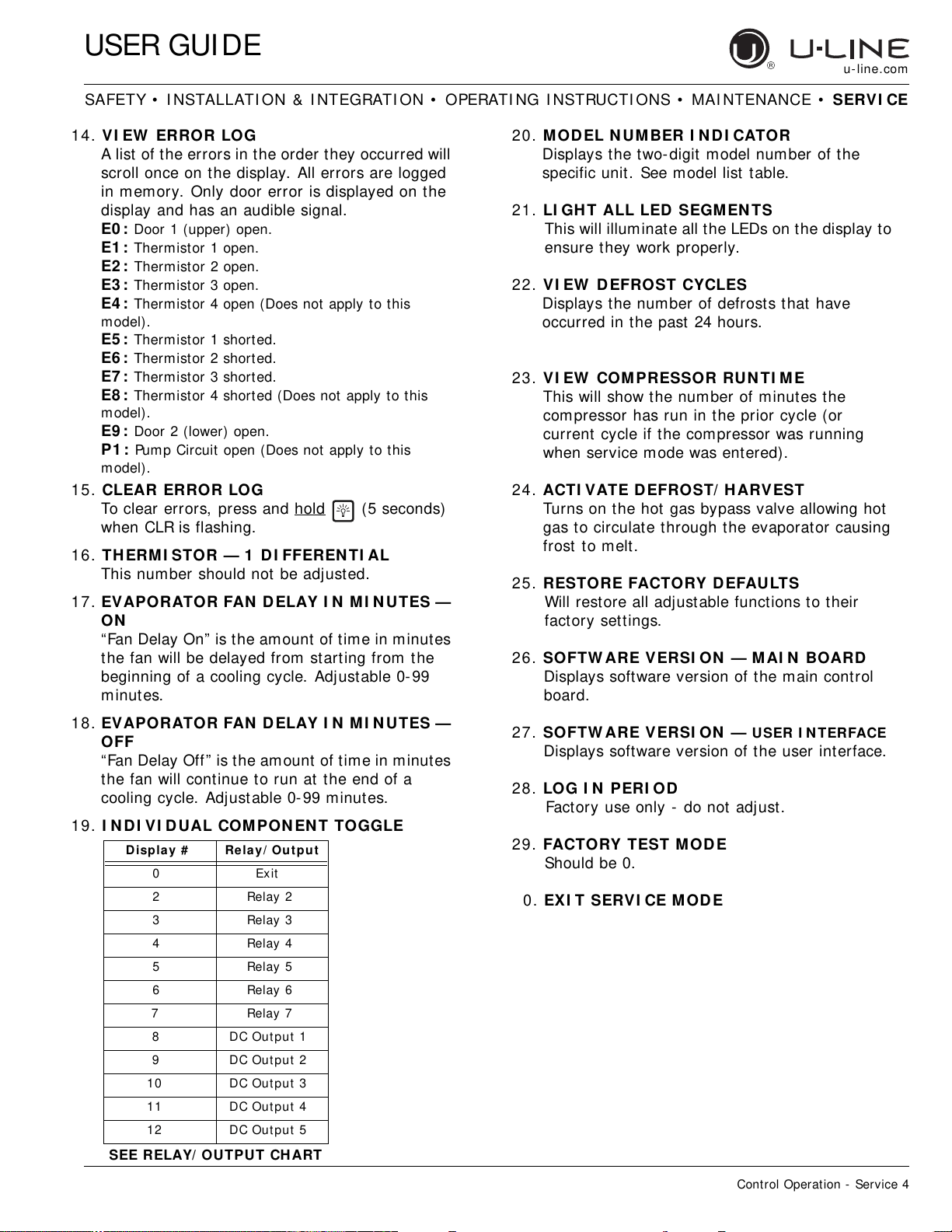
USER GUIDE
Control Operation - Service 4
u-line.com
SAFETY • INSTALLATION & INTEGRATION • OPERATI NG INSTRUCTIONS • MAI NTENANCE • SERV I CE
14. VI EW ERROR LOG
A list of the errors in the order they occurred will
scroll once on the display. All errors are logged
in memory. Only door error is displayed on the
display and has an audible signal.
E0 : Door 1 (upper) open.
E1 : Thermistor 1 open.
E2 : Thermistor 2 open.
E3 : Thermistor 3 open.
E4 : Thermistor 4 open (Does not apply to this
model).
E5 : Thermistor 1 shorted.
E6 : Thermistor 2 shorted.
E7 : Thermistor 3 shorted.
E8 : Thermistor 4 shorted (Does not apply to this
model).
E9 : Door 2 (lower) open.
P1 : Pump Circuit open (Does not apply to this
model).
15. CLEAR ERROR LOG
To clear errors, press and hold
(5 seconds)
when CLR is flashing.
16. THERM I STOR — 1 DI FFEREN TI AL
This number should not be adjusted.
17. EVAPORATOR FAN DELAY I N M I N UTES —
ON
“Fan Delay On” is the amount of time in minutes
the fan will be delayed from starting from the
beginning of a cooling cycle. Adjustable 0- 99
minutes.
18. EVAPORATOR FAN DELAY I N M I N UTES —
OFF
“ Fan Delay Off ” is t h e am oun t of t im e in m inu t es
the fan will continue to run at the end of a
cooling cycle. Adjust able 0- 99 minutes.
19. I N D I VI DUAL COMPON EN T TOGGLE
20. M ODEL N UMBER I N DI CATOR
Displays the two- digit model number of the
specific unit. See model list table.
21. LI GH T ALL LED SEGM EN TS
This will illuminate all the LEDs on the display to
ensure they work properly.
22. VI EW D EFROST CYCLES
Displays the number of defrosts that have
occurred in the past 24 hours.
23. VI EW COMPRESSOR RUN TI ME
This will show the number of minutes the
compressor has run in the prior cycle (or
current cycle if the compressor was running
when service mode was entered).
24. ACTI VATE D EFROST/ HARVEST
Turns on the hot gas bypass valve allowing hot
gas to circulate through the evaporator causing
frost to melt.
25. RESTORE FACTORY DEFAULTS
Will restore all adjustable functions to their
factory settings.
26. SOFTW ARE VERSI ON — MAI N BOARD
Displays software version of the m ain control
board.
27. SOFTW ARE VERSI ON —
USER I NTERFACE
Displays software version of the user interface.
28. LO G I N PERI OD
Factory use only - do not adjust.
29. FACTORY TEST M ODE
Should be 0.
0. EXI T SERVI CE M OD E
Display # Re lay/ Out put
0 Exit
2 Relay 2
3 Relay 3
4 Relay 4
5 Relay 5
6 Relay 6
7 Relay 7
8 DC Out put 1
9 DC Out put 2
10 DC Out put 3
11 DC Out put 4
12 DC Out put 5
SEE RELAY/ OUTPUT CH ART
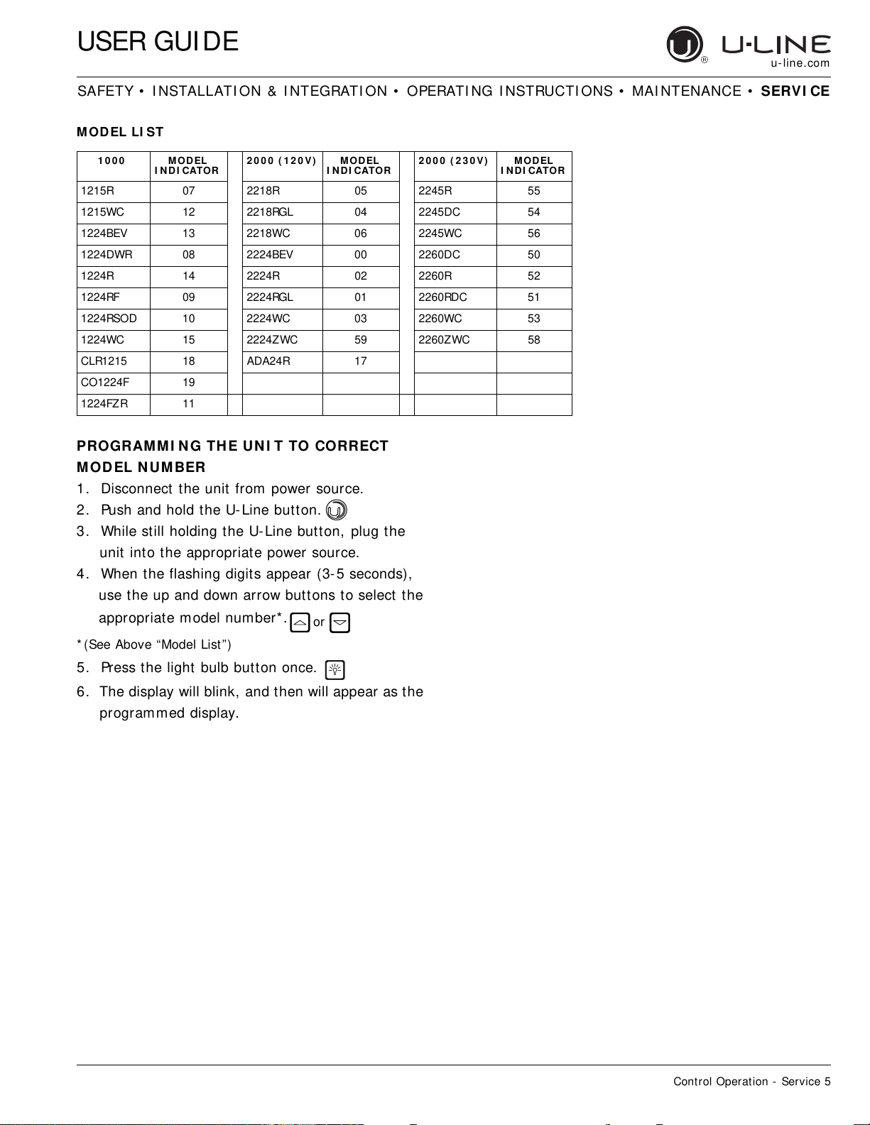
USER GUIDE
Control Operation - Service 5
u-line.com
SAFETY • INSTALLATION & INTEGRATION • OPERATI NG INSTRUCTIONS • MAI NTENANCE • SERV I CE
MOD EL LI ST
PROGRAM MI N G TH E UN I T TO CORRECT
MOD EL N UM BER
1. Disconnect the unit from power source.
2. Push and hold the U-Line button.
3. While still holding the U-Line button, plug the
unit into the appropriate power source.
4. When the flashing digits appear (3- 5 seconds),
use the up and down arrow buttons to select the
appropriate model number*.
* (See Above “Model List”)
5. Press the light bulb button once.
6. The display will blink, and then will appear as the
programmed display.
1 0 0 0 MOD EL
I NDI CATOR
2 0 0 0 ( 1 2 0 V) MODEL
I NDI CATOR
2 0 0 0 ( 2 3 0 V ) M ODEL
I NDI CATOR
1215R 07 2218R 05 2245R 55
1215WC 12 2218RGL 04 2245DC 54
1224BEV 13 2218WC 06 2245WC 56
1224DWR 08 2224BEV 00 2260DC 50
1224R 14 2224R 02 2260R 52
1224RF 09 2224RGL 01 2260RDC 51
1224RSOD 10 2224WC 03 2260WC 53
1224WC 15 2224ZWC 59 2260ZWC 58
CLR1215 18 ADA24R 17
CO1224F 19
1224FZR 11
or
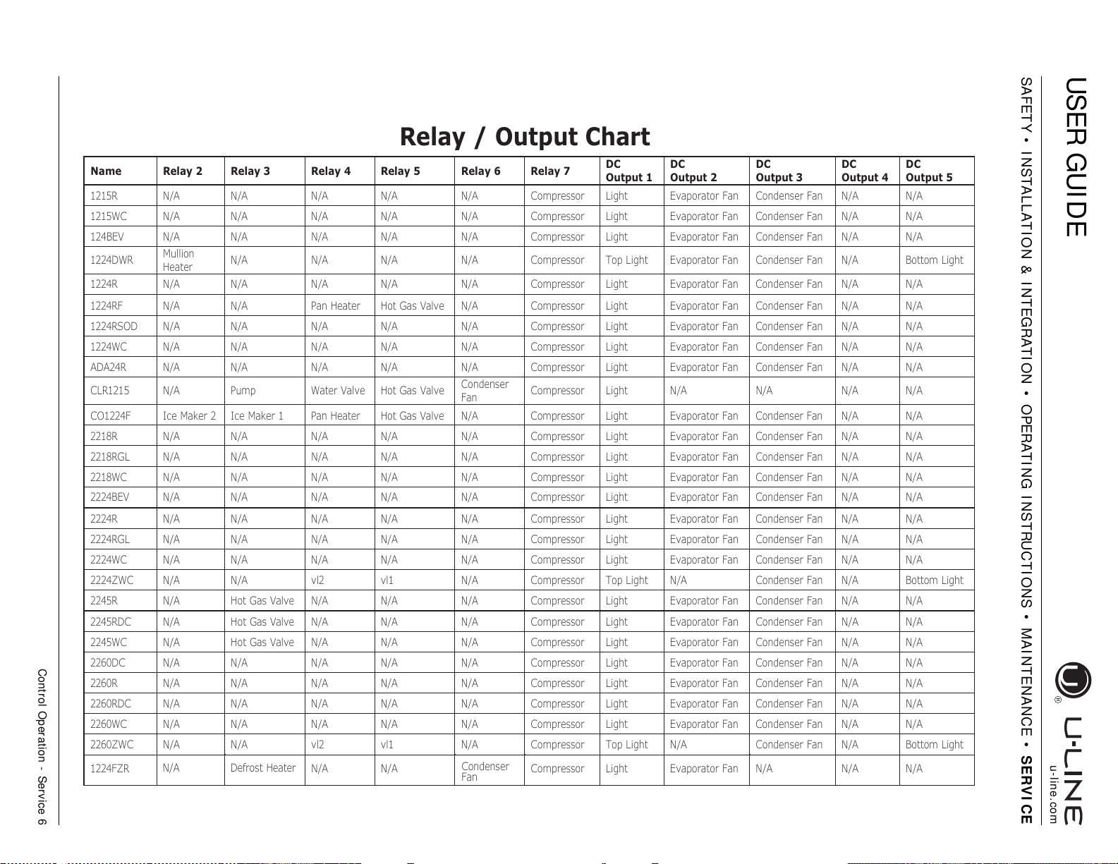
USER GUIDE
Control Operation - Service 6
u-line.com
SAFETY • INSTALLATION & INTEGRATION • OPERATI NG INSTRUCTIONS • MAI NTENANCE • SERV I CE
Name Relay 2 Relay 3 Relay 4 Relay 5 Relay 6 Relay 7
DC
Out
p
ut 1
DC
Out
p
ut 2
DC
Out
p
ut 3
DC
Out
p
ut 4
DC
Out
p
ut 5
1215R N/A N/A N/A N/A N/A Compressor Light Evaporator Fan Condenser Fan N/A N/A
1215WC N/A N/A N/A N/A N/A Compressor Light Evaporator Fan Condenser Fan N/A N/A
124BEV N/A N/A N/A N/A N/A Compressor Light Evaporator Fan Condenser Fan N/A N/A
1224DWR
Mullion
Heater
N/A N/A N/A N/A Compressor Top Light Evaporator Fan Condenser Fan N/A Bottom Light
1224R N/A N/A N/A N/A N/A Compressor Light Evaporator Fan Condenser Fan N/A N/A
1224RF N/A N/A Pan Heater Hot Gas Valve N/A Compressor Light Evaporator Fan Condenser Fan N/A N/A
1224RSOD N/A N/A N/A N/A N/A Compressor Light Evaporator Fan Condenser Fan N/A N/A
1224WC N/A N/A N/A N/A N/A Compressor Light Evaporator Fan Condenser Fan N/A N/A
ADA24R N/A N/A N/A N/A N/A Compressor Light Evaporator Fan Condenser Fan N/A N/A
CLR1215 N/A Pump Water Valve Hot Gas Valve
Condenser
Fan
Compressor Light N/A N/A N/A N/A
CO1224F Ice Maker 2 Ice Maker 1 Pan Heater Hot Gas Valve N/A Compressor Light Evaporator Fan Condenser Fan N/A N/A
2218R N/A N/A N/A N/A N/A Compressor Light Evaporator Fan Condenser Fan N/A N/A
2218RGL N/A N/A N/A N/A N/A Compressor Light Evaporator Fan Condenser Fan N/A N/A
2218WC N/A N/A N/A N/A N/A Compressor Light Evaporator Fan Condenser Fan N/A N/A
2224BEV N/A N/A N/A N/A N/A Compressor Light Evaporator Fan Condenser Fan N/A N/A
2224R N/A N/A N/A N/A N/A Compressor Light Evaporator Fan Condenser Fan N/A N/A
2224RGL N/A N/A N/A N/A N/A Compressor Light Evaporator Fan Condenser Fan N/A N/A
2224WC N/A N/A N/A N/A N/A Compressor Light Evaporator Fan Condenser Fan N/A N/A
2224ZWC N/A N/A vl2 vl1 N/A Compressor Top Light N/A Condenser Fan N/A Bottom Light
2245R N/A Hot Gas Valve N/A N/A N/A Compressor Light Evaporator Fan Condenser Fan N/A N/A
2245RDC N/A Hot Gas Valve N/A N/A N/A Compressor Light Evaporator Fan Condenser Fan N/A N/A
2245WC N/A Hot Gas Valve N/A N/A N/A Compressor Light Evaporator Fan Condenser Fan N/A N/A
2260DC N/A N/A N/A N/A N/A Compressor Light Evaporator Fan Condenser Fan N/A N/A
2260R N/A N/A N/A N/A N/A Compressor Light Evaporator Fan Condenser Fan N/A N/A
2260RDC N/A N/A N/A N/A N/A Compressor Light Evaporator Fan Condenser Fan N/A N/A
2260WC N/A N/A N/A N/A N/A Compressor Light Evaporator Fan Condenser Fan N/A N/A
2260ZWC N/A N/A vl2 vl1 N/A Compressor Top Light N/A Condenser Fan N/A Bottom Light
1224FZR
Defrost Heater
N/A
N/A
N/A
Condenser
Fan
Compressor
Light
Evaporator Fan
N/A
N/A N/A
Relay / Output Chart
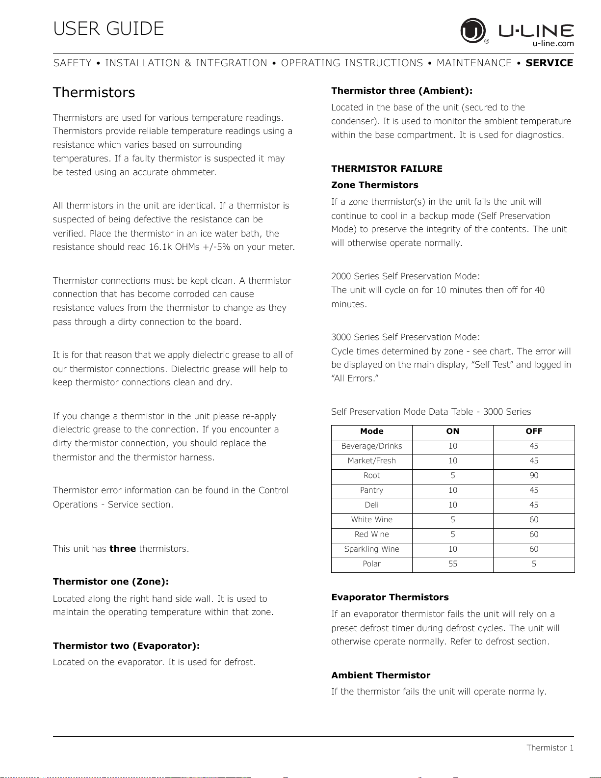
USER GUIDE
Thermistor 1
u-line.com
SAFETY • INSTALLATION & INTEGRATION • OPERATING INSTRUCTIONS • MAINTENANCE • SERVICE
Thermistors
Thermistors are used for various temperature readings.
Thermistors provide reliable temperature readings using a
resistance which varies based on surrounding
temperatures. If a faulty thermistor is suspected it may
be tested using an accurate ohmmeter.
All thermistors in the unit are identical. If a thermistor is
suspected of being defective the resistance can be
verified. Place the thermistor in an ice water bath, the
resistance should read 16.1k OHMs +/-5% on your meter.
Thermistor connections must be kept clean. A thermistor
connection that has become corroded can cause
resistance values from the thermistor to change as they
pass through a dirty connection to the board.
It is for that reason that we apply dielectric grease to all of
our thermistor connections. Dielectric grease will help to
keep thermistor connections clean and dry.
If you change a thermistor in the unit please re-apply
dielectric grease to the connection. If you encounter a
dirty thermistor connection, you should replace the
thermistor and the thermistor harness.
Thermistor error information can be found in the Control
Operations - Service section.
This unit has three thermistors.
Thermistor one (Zone):
Located along the right hand side wall. It is used to
maintain the operating temperature within that zone.
Thermistor two (Evaporator):
Located on the evaporator. It is used for defrost.
Thermistor three (Ambient):
Located in the base of the unit (secured to the
condenser). It is used to monitor the ambient temperature
within the base compartment. It is used for diagnostics.
THERMISTOR FAILURE
Zone Thermistors
If a zone thermistor(s) in the unit fails the unit will
continue to cool in a backup mode (Self Preservation
Mode) to preserve the integrity of the contents. The unit
will otherwise operate normally.
2000 Series Self Preservation Mode:
The unit will cycle on for 10 minutes then off for 40
minutes.
3000 Series Self Preservation Mode:
Cycle times determined by zone - see chart. The error will
be displayed on the main display, “Self Test” and logged in
“All Errors.”
Self Preservation Mode Data Table - 3000 Series
Evaporator Thermistors
If an evaporator thermistor fails the unit will rely on a
preset defrost timer during defrost cycles. The unit will
otherwise operate normally. Refer to defrost section.
Ambient Thermistor
If the thermistor fails the unit will operate normally.
Mode ON OFF
Beverage/Drinks 10 45
Market/Fresh 10 45
Root 5 90
Pantry 10 45
Deli 10 45
White Wine 5 60
Red Wine 5 60
Sparkling Wine 10 60
Polar 55 5
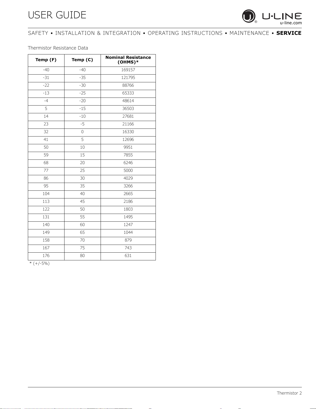
USER GUIDE
Thermistor 2
u-line.com
SAFETY • INSTALLATION & INTEGRATION • OPERATING INSTRUCTIONS • MAINTENANCE • SERVICE
Thermistor Resistance Data
Temp (F) Temp (C)
Nominal Resistance
(OHMS)*
-40 -40 169157
-31 -35 121795
-22 -30 88766
-13 -25 65333
-4 -20 48614
5 -15 36503
14 -10 27681
23 -5 21166
32 0 16330
41 5 12696
50 10 9951
59 15 7855
68 20 6246
77 25 5000
86 30 4029
95 35 3266
104 40 2665
113 45 2186
122 50 1803
131 55 1495
140 60 1247
149 65 1044
158 70 879
167 75 743
176 80 631
* (+/-5%)
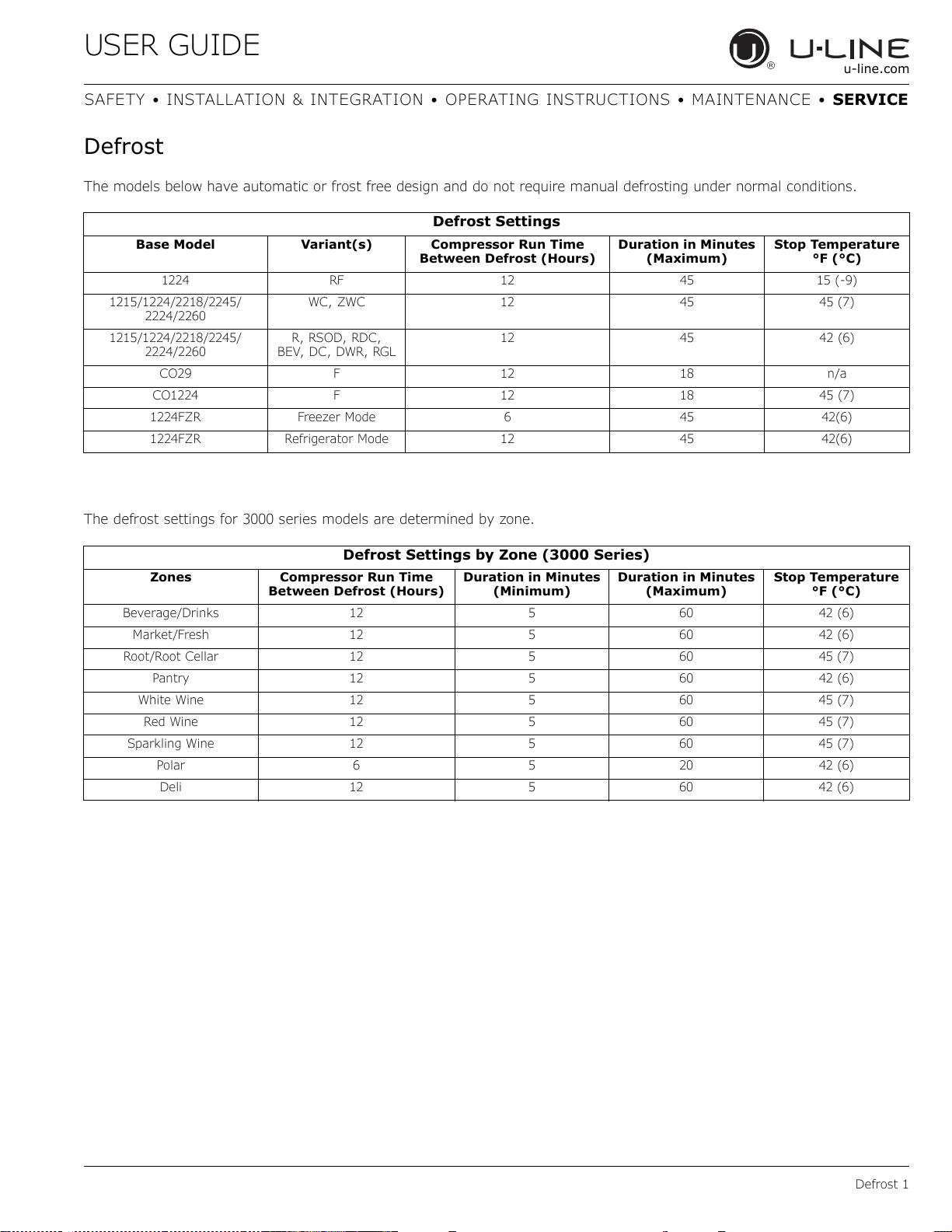
USER GUIDE
Defrost 1
u-line.com
SAFETY • INSTALLATION & INTEGRATION • OPERATING INSTRUCTIONS • MAINTENANCE • SERVICE
Defrost
The models below have automatic or frost free design and do not require manual defrosting under normal conditions.
The defrost settings for 3000 series models are determined by zone.
Defrost Settings
Base Model Variant(s) Compressor Run Time
Between Defrost (Hours)
Duration in Minutes
(Maximum)
Stop Temperature
°F (°C)
1224 RF 12 45 15 (-9)
1215/1224/2218/2245/
2224/2260
WC, ZWC 12 45 45 (7)
1215/1224/2218/2245/
2224/2260
R, RSOD, RDC,
BEV, DC, DWR, RGL
12 45 42 (6)
CO29 F 12 18 n/a
CO1224 F 12 18 45 (7)
1224FZR Freezer Mode 6 45 42(6)
1224FZR Refrigerator Mode 12 45 42(6)
Defrost Settings by Zone (3000 Series)
Zones Compressor Run Time
Between Defrost (Hours)
Duration in Minutes
(Minimum)
Duration in Minutes
(Maximum)
Stop Temperature
°F (°C)
Beverage/Drinks 12 5 60 42 (6)
Market/Fresh 12 5 60 42 (6)
Root/Root Cellar 12 5 60 45 (7)
Pantry 12 5 60 42 (6)
White Wine 12 5 60 45 (7)
Red Wine 12 5 60 45 (7)
Sparkling Wine 12 5 60 45 (7)
Polar 6 5 20 42 (6)
Deli 12 5 60 42 (6)
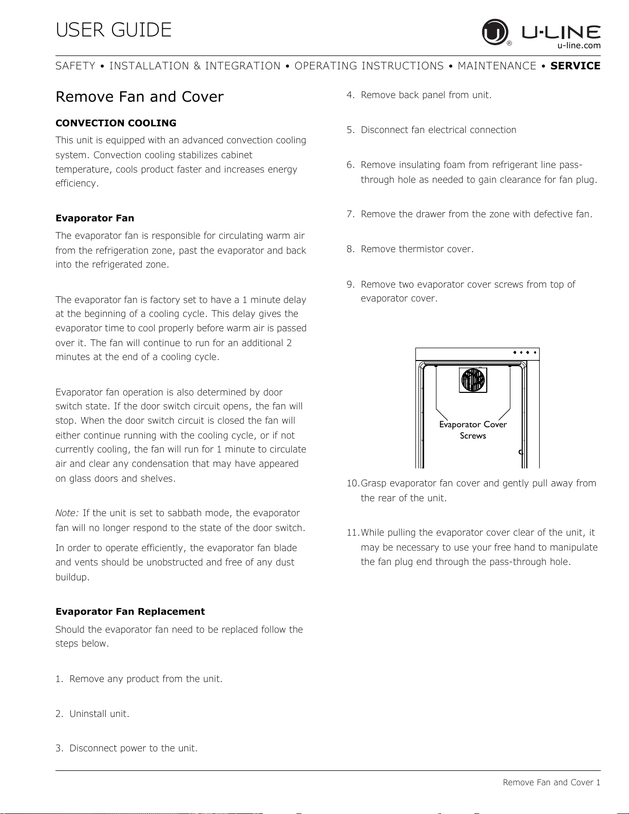
USER GUIDE
Remove Fan and Cover 1
u-line.com
SAFETY • INSTALLATION & INTEGRATION • OPERATING INSTRUCTIONS • MAINTENANCE • SERVICE
Remove Fan and Cover
CONVECTION COOLING
This unit is equipped with an advanced convection cooling
system. Convection cooling stabilizes cabinet
temperature, cools product faster and increases energy
efficiency.
Evaporator Fan
The evaporator fan is responsible for circulating warm air
from the refrigeration zone, past the evaporator and back
into the refrigerated zone.
The evaporator fan is factory set to have a 1 minute delay
at the beginning of a cooling cycle. This delay gives the
evaporator time to cool properly before warm air is passed
over it. The fan will continue to run for an additional 2
minutes at the end of a cooling cycle.
Evaporator fan operation is also determined by door
switch state. If the door switch circuit opens, the fan will
stop. When the door switch circuit is closed the fan will
either continue running with the cooling cycle, or if not
currently cooling, the fan will run for 1 minute to circulate
air and clear any condensation that may have appeared
on glass doors and shelves.
Note: If the unit is set to sabbath mode, the evaporator
fan will no longer respond to the state of the door switch.
In order to operate efficiently, the evaporator fan blade
and vents should be unobstructed and free of any dust
buildup.
Evaporator Fan Replacement
Should the evaporator fan need to be replaced follow the
steps below.
1. Remove any product from the unit.
2. Uninstall unit.
3. Disconnect power to the unit.
4. Remove back panel from unit.
5. Disconnect fan electrical connection
6. Remove insulating foam from refrigerant line pass-
through hole as needed to gain clearance for fan plug.
7. Remove the drawer from the zone with defective fan.
8. Remove thermistor cover.
9. Remove two evaporator cover screws from top of
evaporator cover.
10.Grasp evaporator fan cover and gently pull away from
the rear of the unit.
11.While pulling the evaporator cover clear of the unit, it
may be necessary to use your free hand to manipulate
the fan plug end through the pass-through hole.
Evaporator Cover
Screws
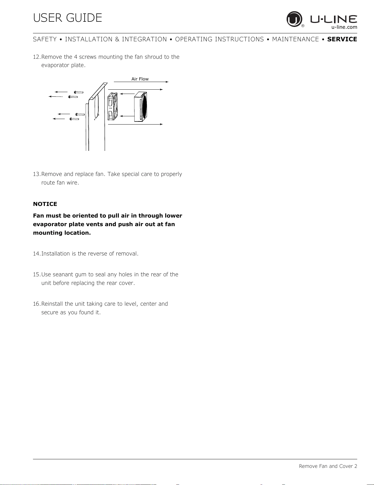
USER GUIDE
Remove Fan and Cover 2
u-line.com
SAFETY • INSTALLATION & INTEGRATION • OPERATING INSTRUCTIONS • MAINTENANCE • SERVICE
12.Remove the 4 screws mounting the fan shroud to the
evaporator plate.
13.Remove and replace fan. Take special care to properly
route fan wire.
NOTICE
Fan must be oriented to pull air in through lower
evaporator plate vents and push air out at fan
mounting location.
14.Installation is the reverse of removal.
15.Use seanant gum to seal any holes in the rear of the
unit before replacing the rear cover.
16.Reinstall the unit taking care to level, center and
secure as you found it.
Air Flow