Installation and
User's Manual for
Residential Ice Machine
Models SCCG50 and SCCP50

Introduction:
This ice machine is the result of Scotsman’s
decades of experience as an industry leader in the
design and manufacture of both commercial and
residential ice machines.
This manual includes the information needed to
install, start up and maintain the ice machine. Note
any Caution or Warning indicators, as they provide
notice of potential hazards. Keep this manual for
future reference.
June 2008
Page 1
SCCG50 & SCCP50
Installation and User's Manual
Table of Contents
Specifications .......................................... Page 2
Cabinet Layout ......................................... Page 3
Air flow ............................................. Page 4
Water Quality .......................................... Page 5
Door Covering .......................................... Page 6
Door Panel Attachment ..................................... Page 7
Door swing change ....................................... Page 8
Installation: Water & Drain ................................... Page 9
Gravity Drain .......................................... Page 10
Electrical ............................................ Page 11
Use ............................................... Page 12
How to clean the condenser and winterize. ........................... Page 13
How to remove scale from the ice making system. ....................... Page 14
Specifications
This ice machine is designed to be used indoors, in
a controlled environment. It can be used in a wide
variety of environmental conditions, but there are
limits. Use outside of the listed limitations is misuse
and will void the warranty.
Air temperature limits:
The ice machine will operate adequately within the
limits, but functions best in temperatures between
70 and 80 degrees F.
•
Minimum – 50 degrees F. (10
o
C)
•
Maximum – 100 degrees F. (38
o
C)
Water temperature limits:
•
Minimum – 40 degrees F. (4.5
o
C)
•
Maximum – 100 degrees F. (38
o
C)
Water pressure limits:
•
Minimum – 20 psi (1.4 bar)
•
Maximum – 80 psi (5.5 bar)
Because the ice machine is making a food product,
the water supply to the ice machine must be
potable, or fit for human consumption.
Electrical voltage limits:
•
Minimum - 104 volts
•
Maximum – 126 volts
Models
Options:
Door Panels
: Finished door panels are available
from Scotsman for attachment to the machine, or a
custom panel can be made. The panel kits are:
Kit Number Panel Finish Handle Finish
KDFW White White
KDFWS White Stainless Steel
KDFB Black Black
KDFBS Black Stainless Steel
KDFS Stainless Steel Stainless Steel
Kickplate Extension: In some situations the leg
levelers will be extended enough to become visible.
A kit to extend the kickplate over the legs is KKPF.
Cabinet Stability
: In some free standing
installations it may be prudent to add a bracket that
secures the back of the cabinet to a wall. That kit
number is KATB.
Drain Conversion
: A gravity drain model can be
converted to a drain pump model by installing a
drain pump kit. The drain pump kit consists of a
drain pump, wiring harness and associated tubing.
The part number is A39462-021.
Warranty Information
Warranty information is supplied separately from
this manual. Refer to it for coverage. In general, the
warranty covers defects in materials or
workmanship and does not cover corrections of
installation errors or maintenance.
July 2008
Page 2
SCCG50 & SCCP50
Installation and User's Manual
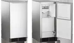
There are six models, all air cooled:
•
SCCP50M-1WU – Pump model, white cabinet
•
SCCG50M-1WU – Gravity drain model, white cabinet
•
SCCP50M-1BU – Pump model, black cabinet
•
SCCG50M-1BU – Gravity drain model, black cabinet
•
SCCP50M-1SU – Pump model, stainless cabinet
•
SCCG50M-1SU – Gravity drain model, stainless cabinet
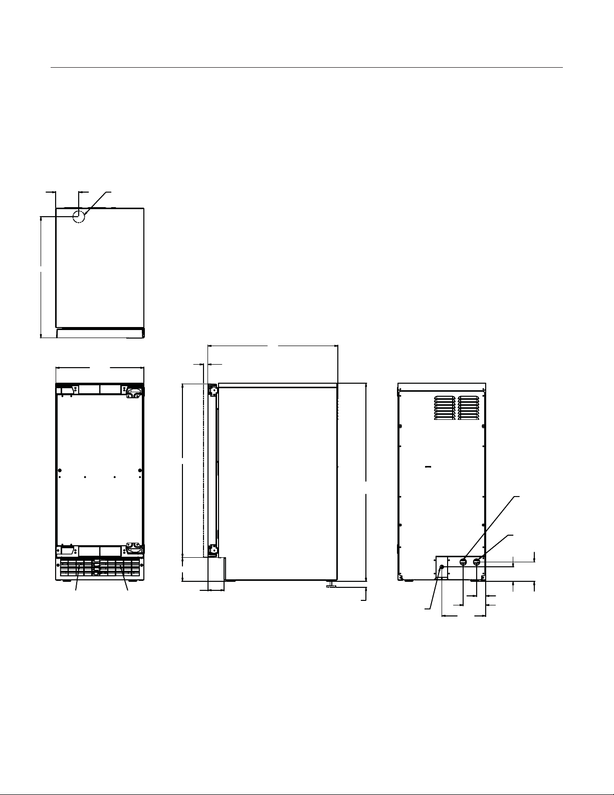
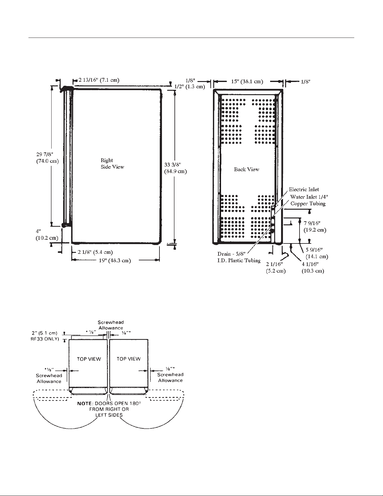
Cabinet Dimensions
Width Depth, w/out door panel Depth, with door panel, handle adds 1 5/8" Height
14 7/8" 22" 22 3/4" 33 3/8" to 34 3/8"
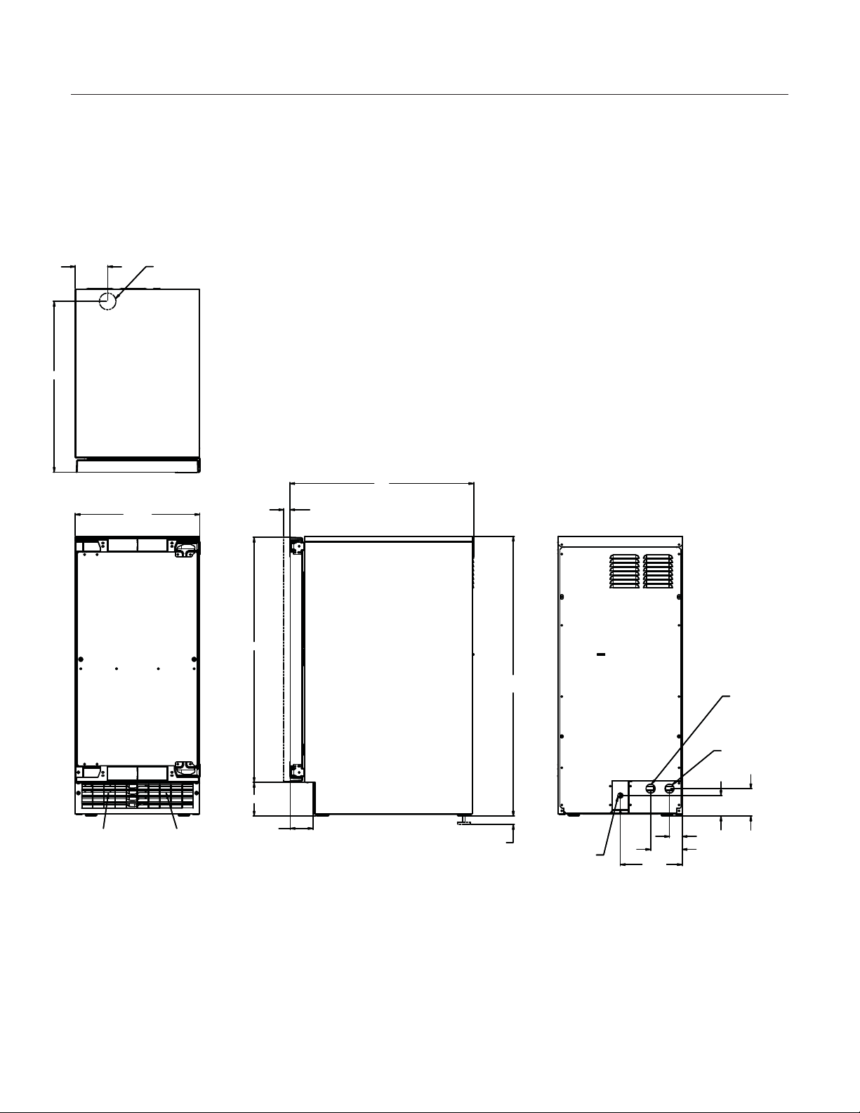
Cabinet Layout
June 2008
Page 3
SCCG50 & SCCP50
Installation and User's Manual
14 7/8"
AIR IN
AIR OUT
.75
SHEET METAL DOOR FRONT
.63 MIN. CABINET DOOR
29 1/4"
1"
LEG ADJUSTMENT
(4) PLACES
33 3/8" MIN.
34 3/8" MAX.
22"
2 3/4"
4"
3 3/4"
1 1/2"
2 1/2"
3 1/4"
7 3/8"
115 V
POWER CORD
DRAIN
FLEXIBLE TUBING
3/8 I.D. PUMP MODEL (INCLUDED)
5/8 I.D. GRAVITY MODEL (NOT INCLUDED)
POTABLE WATER INLET
1/4" COMPRESSION FITTING
3 7/8"
20 3/8"
FLOOR DRAIN
ACCESS HOLE
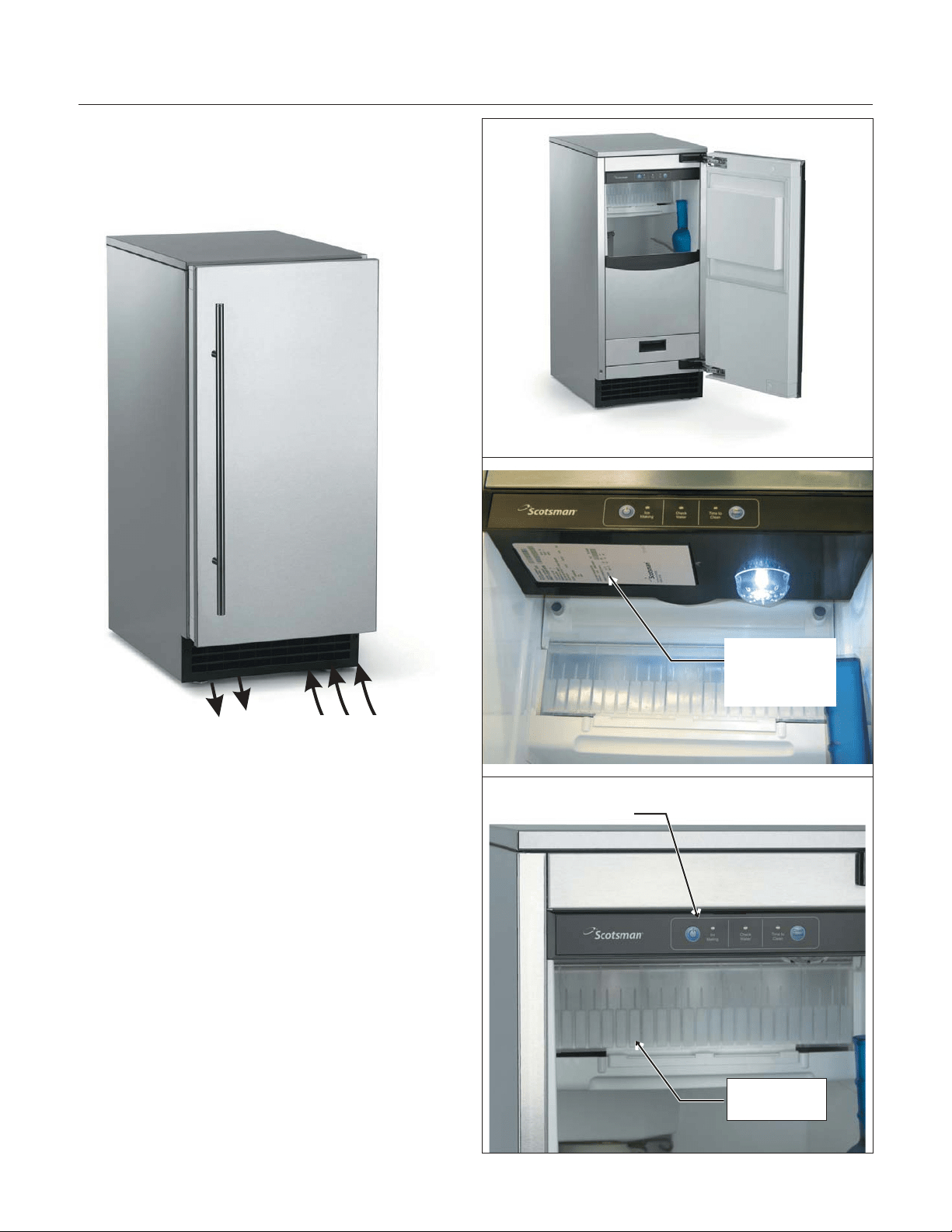
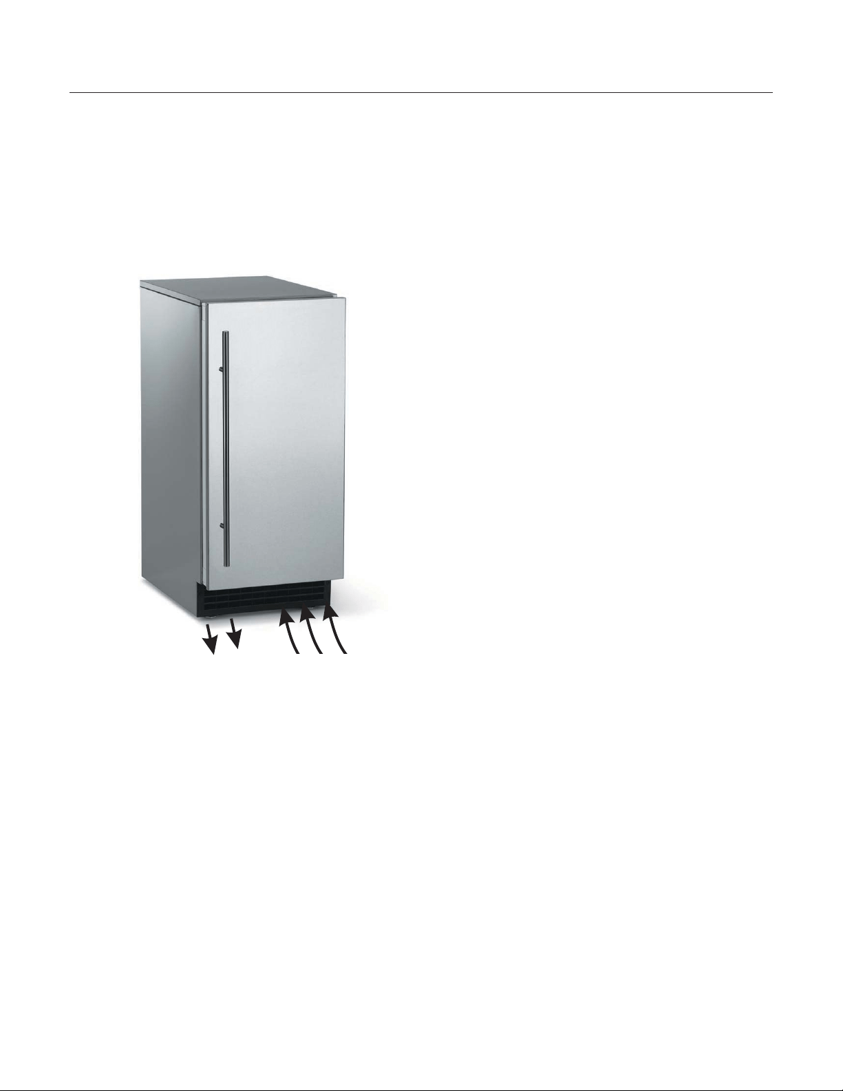
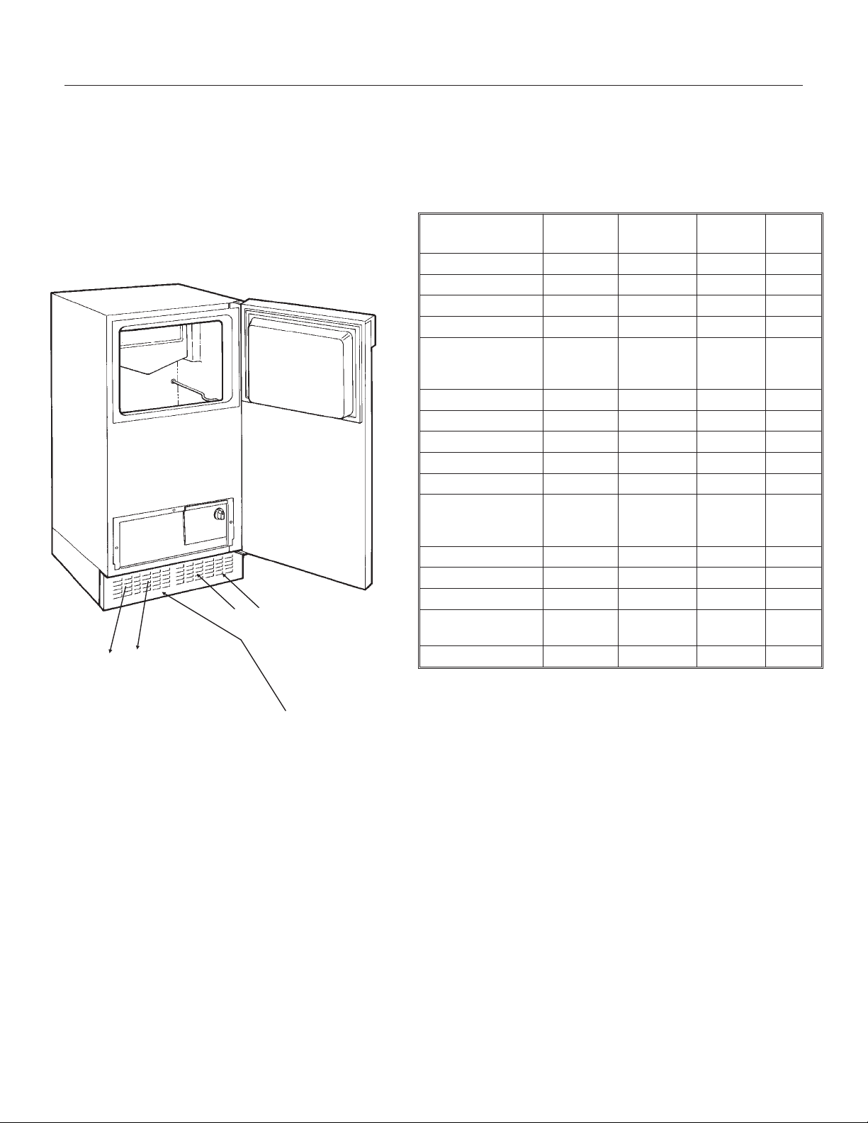
Air flow
The machine takes in room temperature air at the
lower right front and forces warm air out the lower
left front. Restricting the airflow will adversely affect
the ability of the ice machine to make ice.
Scotsman Ice Systems are designed and
manufactured with the highest regard for safety
and performance. They meet or exceed the
standards of agencies like U.L.
Scotsman assumes no liability or responsibility of
any kind for products manufactured by Scotsman
that have been altered in any way, including the
use of any parts and/or other components not
specifically approved by Scotsman.
Scotsman reserves the right to make design
changes and/or improvements at any time.
Specifications and designs are subject to change
without notice.
June 2008
Page 4
SCCG50 & SCCP50
Installation and User's Manual
Air IntakeWarm Air Out
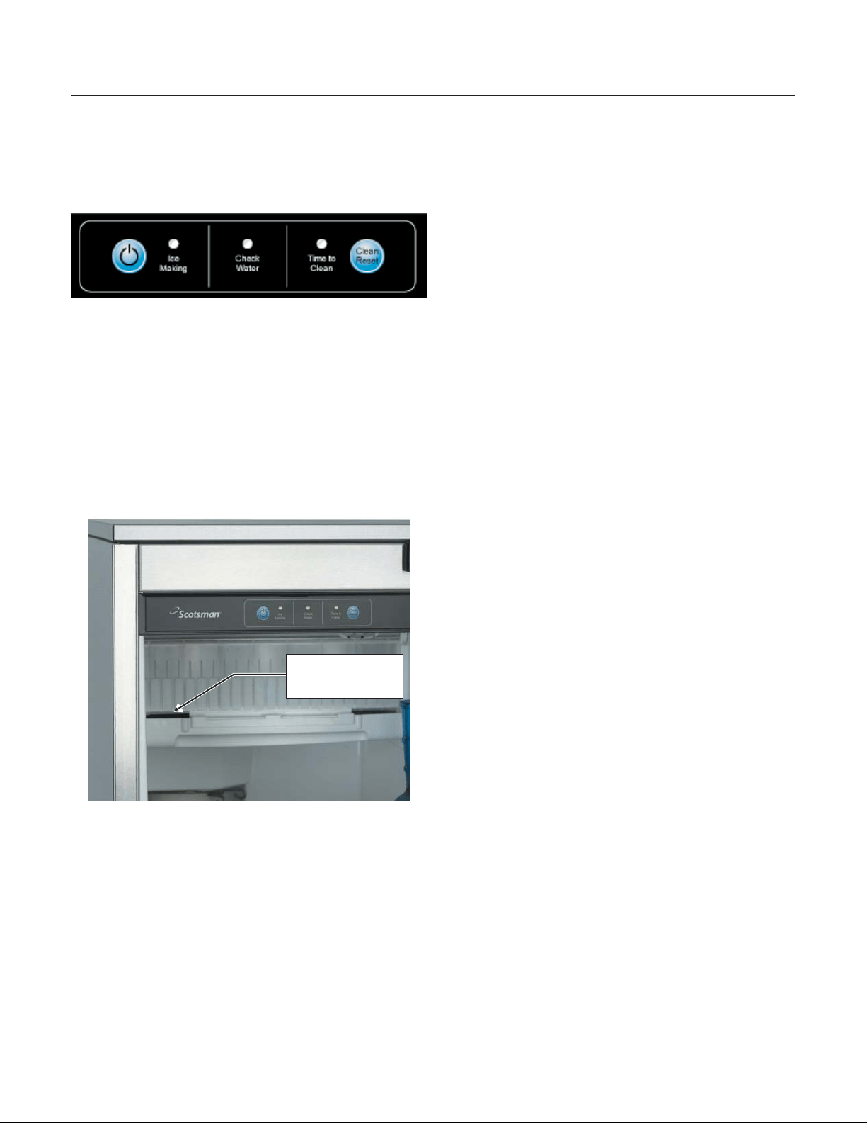
Control Panel
Ice Making
Area
Model and
Serial Number
Tag

Water Quality
All water, including potable water supplied by
municipalities, contains some impurities or
minerals. Water absorbs impurities from the air as
rain and/or as it flows through the ground. Some of
the impurities are solid particles, these are known
as suspended solids, and a fine particle filter will
remove them. Other impurities are chemically
bonded to the water molecules, and cannot be
filtered out, these are called dissolved solids.
Ice made by this machine will have a lower mineral
content than the water it was made from. This is
due to the method of making ice. Purer water will
freeze first in the ice making molds. The reason for
this is that anything dissolved in water lowers the
water’s freezing temperature. This concentrates
most of the impurities in the ice machine water
reservoir where they may form hard deposits
known as scale. The machine dilutes the
concentration of minerals by over-filling the
reservoir during the harvest cycle (with the excess
water flowing down the drain). s. Between 2 and 4
pints of water flow into the unit each cycle.
Between 1 and 3.5 pints of that rinses the reservoir
and goes down the drain.
Some impurities will inevitably remain, and will stick
to the parts in the machine, and will cause
malformed ice cubes. Eventually, built up mineral
scale can shorten machine life.
To keep the machine operating properly, these
impurities or minerals will have to be regularly
dissolved by an acid cleaning, using Scotsman Ice
Machine Scale Remover. Directions for this may be
found in the section under cleaning.
Filters and Treatment
In general, it is always a good idea to filter the
water. A water filter, if it is of the proper type, can
remove taste and odors as well as particles. Some
methods of water treatment for dissolved solids
include reverse osmosis, and polyphosphate
feeders.
RO Water
This machine can be supplied with Reverse
Osmosis water, but the water conductivity must be
no less than 10 microSiemens/cm. A reverse
osmosis system should include post treatment to
satisfy the R.O. water’s potential aggressiveness.
Deionized water is not recommended.
Because water softeners exchange one mineral for
another, softened water may not improve water
conditions when used with ice machines. Where
water is very hard, softened water could result in
white, mushy cubes that stick together.
If in doubt about the water, contact a local point of
use water specialist for recommendations on water
treatment.
Installation Overview
The ice machine must:
•
be connected to cold, potable water
•
be connected to a drain
•
be connected to the proper power supply
•
be able circulate air through the vents at the
front.
Note: Do not build in so that the door is recessed.
June 2008
Page 5
SCCG50 & SCCP50
Installation and User's Manual

Door Covering
Door Panel
The ice machine is supplied without a conventional
door covering so it can be decorated to the user’s
preference. Scotsman offers several coverings
including white, black and stainless steel. In
addition, a custom built panel can be placed onto
the door.
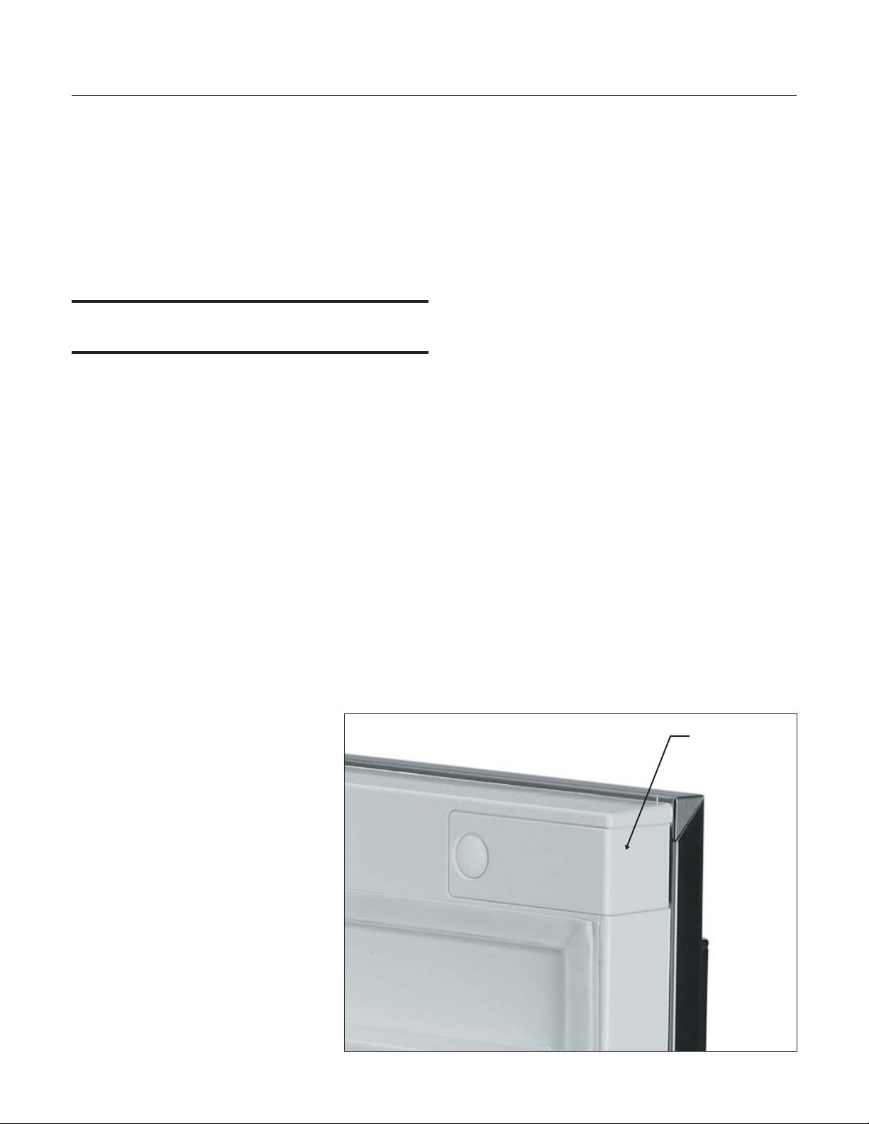
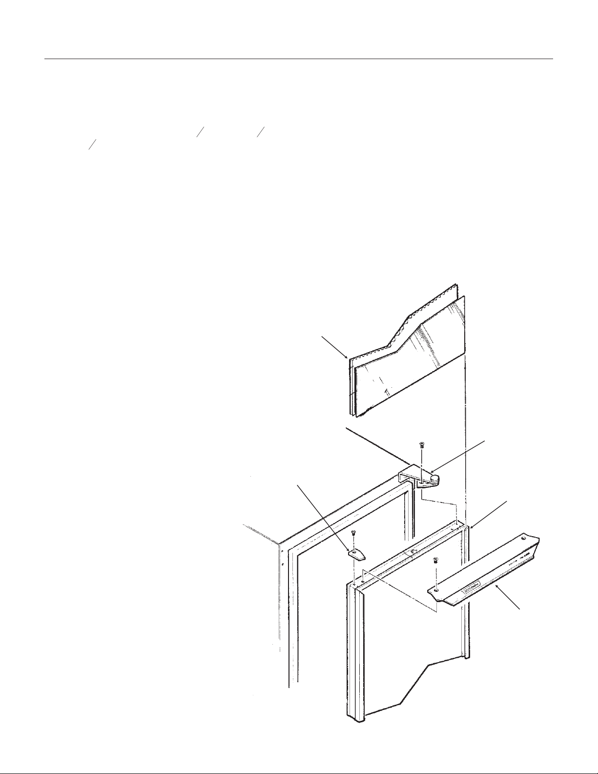
Door Panel Attachment
To attach a Scotsman supplied panel:
Note: If door swing is to be changed, it must be
done before panel is attached.
The panel will be held on by 6 sheet metal screws
and 2 machine screws.
1. Remove the gasket and retain for later use.
2. If the door panel is stainless steel, remove any
plastic covering the stainless steel panel.
3. Place the panel onto the outside of the door,
and secure it to the door using two machine
screws, located at the left center and right
center.
4. Fasten the panel to the door using the 6 sheet
metal screws. In the hinge area, use the
outermost screw holes.
5. Place the covers over the hinge
areas, and secure each cover to
the door using a sheet metal
screw.
6. Insert hole plug over screw
installed in step 5.
7. Return the gasket to its original
position.
Custom Panel
A custom panel of wood or other material not
exceeding 15 lb can be attached to the door.
Attachment is from the ice side of the door. Holes
are provided in the door for this purpose.
See instructions in information packet to create and
attach a custom panel:
June 2008
Page 6
SCCG50 & SCCP50
Installation and User's Manual
Hole Plug
Cover
Gasket
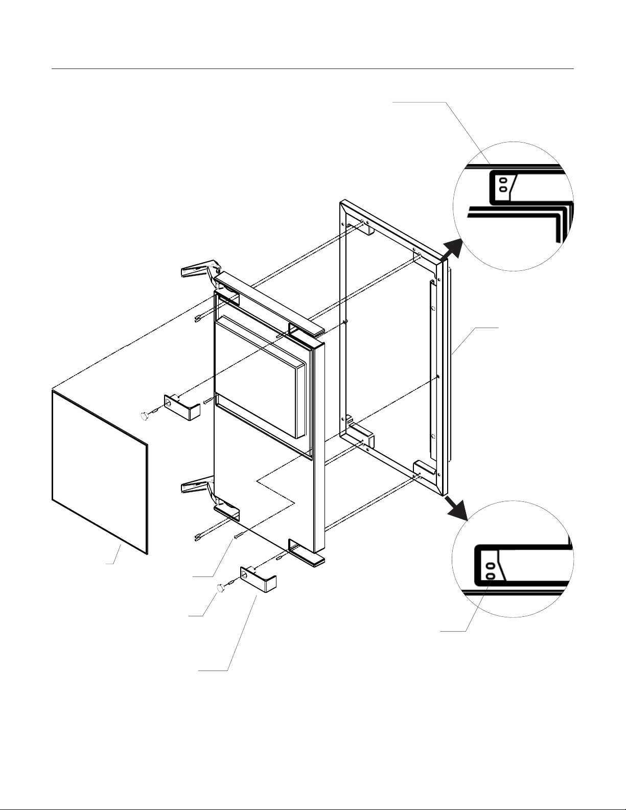
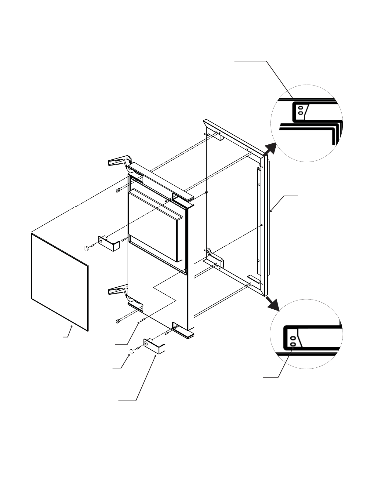
Door Panel Attachment
June 2008
Page 7
SCCG50 & SCCP50
Installation and User's Manual
Gasket
Scotsman
Door Panel
Cover
Machine
Screw
Use Upper
Hole at the
Top
Use Lower
Hole at the
Bottom
Hole Plug
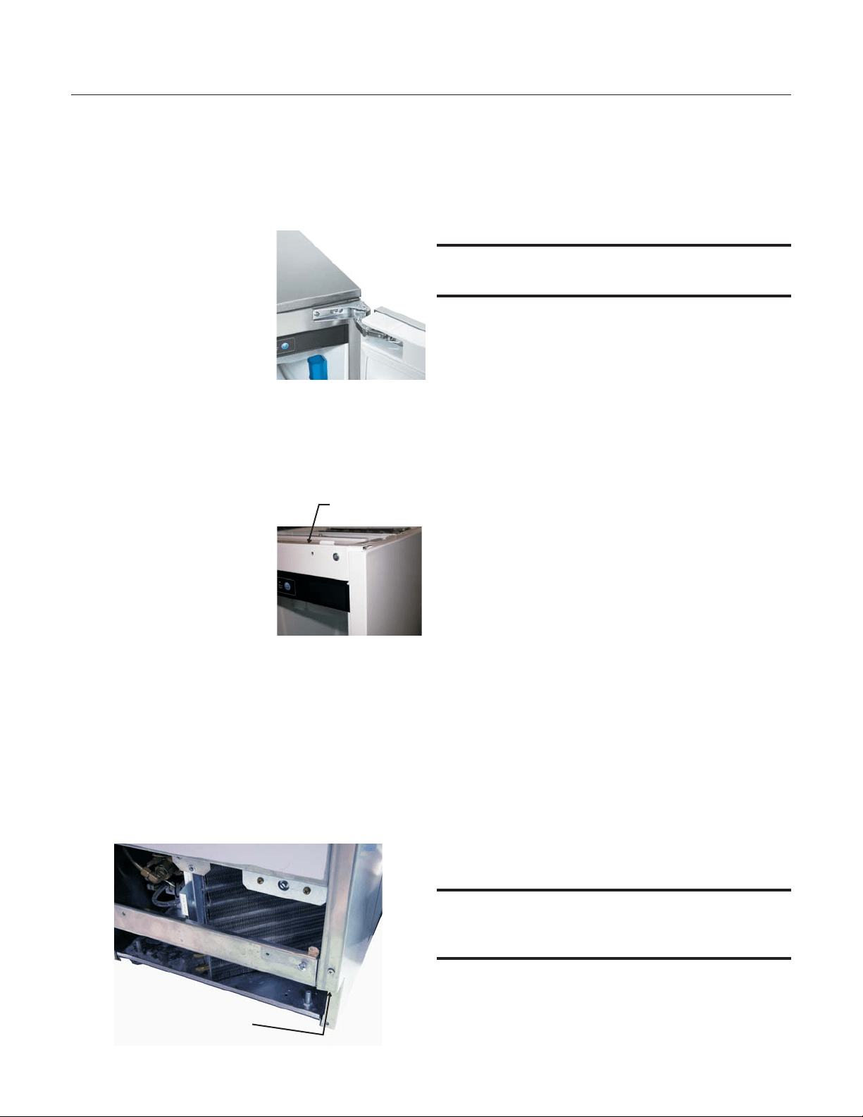
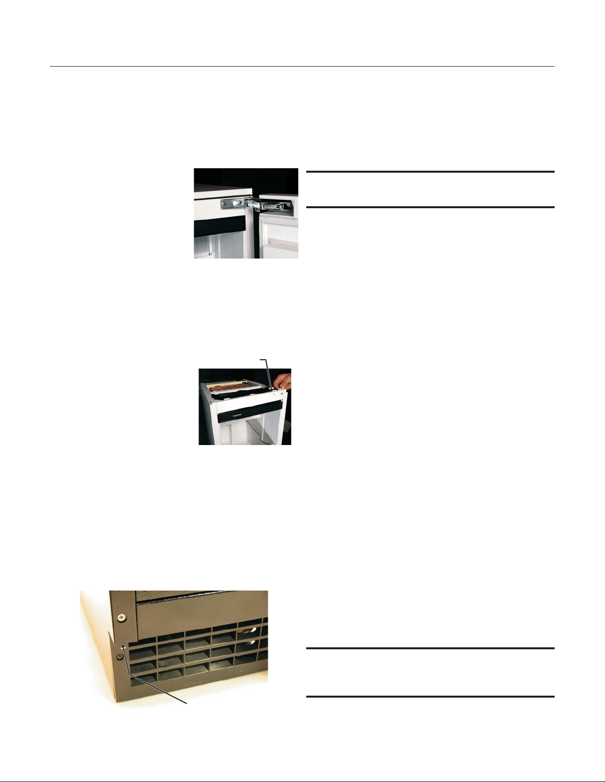
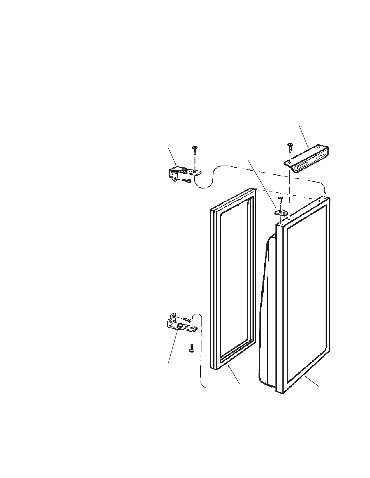
Door swing change
The door can be attached to open with hinges on
the left or right using new hinge brackets shipped
loose in the ice bin. Retain all screws for re-use.
To change:
1. Remove innermost
screw holding each
hinge to cabinet, loosen
the other.
2. Slide hinges to the side
and remove door from
cabinet. Remove
screws loosened in step
1 from both cross
braces.
3. Remove two screws securing top panel to
back, pull top panel back and remove from
cabinet.
4. Remove two screws at
the top and lift the
upper bracket out of
the cabinet. Replace
with the one supplied
loose with the machine.
Fasten it to the cabinet
using the original
screws.
5. Return the top panel to the cabinet and fasten
it with the original screws.
6. Remove kickplate and front service panel.
7. Remove two front screws and two bottom
screws holding the bottom door bracket to the
cabinet.
8. Replace the bracket with the one supplied
loose with the machine. Secure it using the
original screws.
9. Remove the upper hinge and move it to the
door's opposite side, bottom location. Secure
using the original screws.
Note: If door panel is attached, it must be removed
to access hinge screws.
10. Remove the original lower hinge and move it to
the door's opposite side, upper location.
Secure using the original screws.
11. Install a screw removed in step 2 in outermost
hole of upper and lower cross braces.
12. Attach the door to the cabinet using the original
screws.
13. Return kickplate and front service panel to their
original positions and attach to the cabinet
using the original screws.
Installation Notes
Built In Situations: If a finished floor is to be
installed in the area after the ice machine has been
built in, shims the expected thickness of the floor
should be installed under the unit to keep the
machine level with the planned floor level.
Installations on a slab: Use a pump model and
pump the water to the point of drainage. Pump
models will pump 1 story (10 feet) high.
Installations over a crawl space or basement:
Either gravity drain or pump model units may be
used, if there is not enough room behind the
machine for a drain/waste receptacle, the drain will
have to be below the floor.
Note: When installed in a corner, the door swing
may be limited due to handle contact with the wall
or cabinet face.
June 2008
Page 8
SCCG50 & SCCP50
Installation and User's Manual
Screw Below
Upper
Bracket
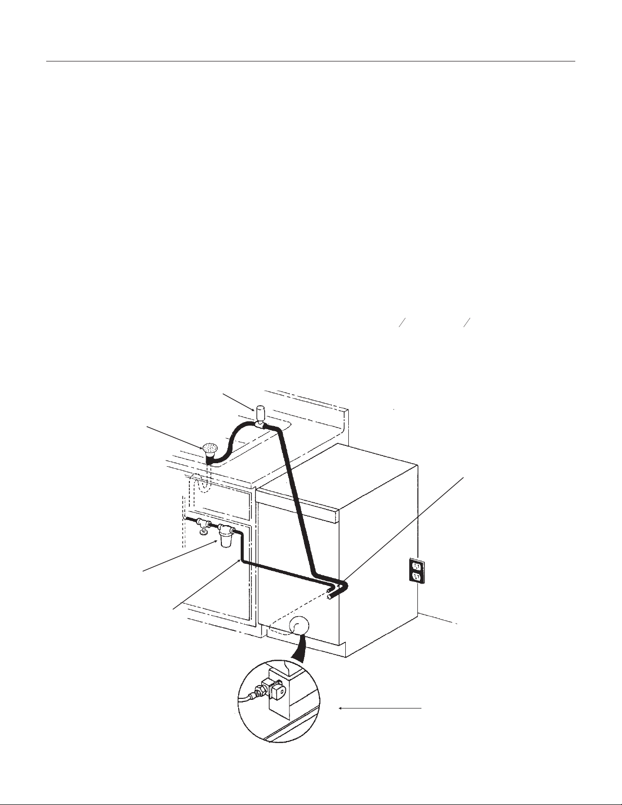
Installation: Water & Drain
The recommended water supply tubing is ¼ inch
OD copper. Stainless steel flex or reinforced PCV
tube may also be used. Install an easily accessible
shut-off valve between the supply and the unit. This
shut-off valve should not be installed behind the
unit.
Note: Do not use self-piercing type valves.
1. Remove the front service panel.
2. Route the tubing through the right hole in the
back to the inlet water solenoid valve inlet.
3. Install a compression fitting on the tubing and
connect to the inlet of the solenoid.
Drains
There are two types of ice machine models, one
that drains by gravity and one that has an internal
drain pump.
Drain Pump Model drain installation
1. Locate the coil of 3/8” ID plastic drain tubing
secured to the back of the unit.
2. Route the plastic drain tube from the back of the
unit to the drain connection point.
IMPORTANT NOTE: Often an air gap is required by
local codes between the ice maker drain tube and
the drain receptacle.
June 2008
Page 9
SCCG50 & SCCP50
Installation and User's Manual
Back View, Drain Pump Model
Water Inlet
Tube (field
supplied)
Drain Tube,
Route to
building drain
Screw
Securing
Front Service
Panel
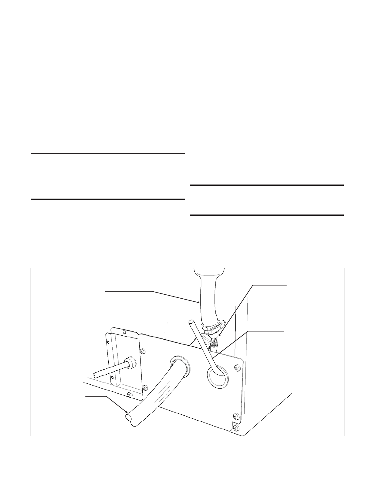
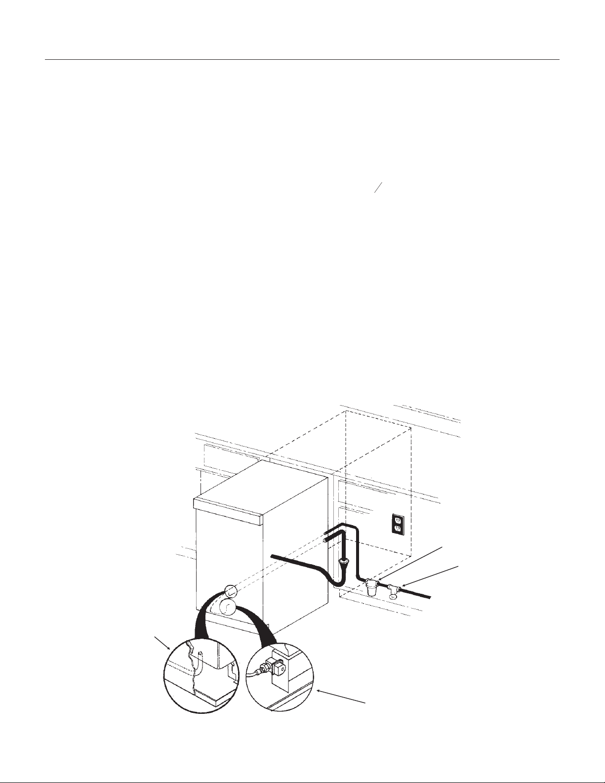
Gravity Drain
Caution: Restrictions in the drain system to the
machine will cause water to back up into the ice
storage bin and melt the ice. Gravity drain tubing
must be vented, have no kinks and slope to the
building drain. Air gaps are typically required by
local code.
1. Place the ice machine in front of the installation
opening. Adjust leveling legs to the approximate
height.
2. Remove the front service access panel and the
upper back panel.
Note: If you are connecting a gravity drain model
and the drain opening has been located in the floor
under the base pan according to the pre install
specifications, follow steps 3 through 5 to drain the
unit through the base. If not, proceed to step 6b.
3. Remove the clamp and barbed elbow and take
off the plastic cover in the base pan below the drain
hose.
4. Connect a straight 5/8” barbed connector to the
drain hose, securing with the clamp removed in
step 4.
5. Cut an 8” piece of 5/8” ID X 7/8” OD tygon (clear
plastic) tubing. Slide one end of the tube onto the
outlet of the barbed connector and secure with a
clamp. Leave the other end of the tube lying on the
floor of the base pan until the unit is positioned
over the floor drain.
6. Route the drain tube. Either a) Insert the drain
tube through the base pan into the floor drain or b)
Route the drain tube through the left hole in the
lower back panel and connect to barbed elbow and
secure with a clamp.
7. Reinstall the upper back panel.
8. Reinstall the service access panel. Level the
unit.
June 2008
Page 10
SCCG50 & SCCP50
Installation and User's Manual
Back View, Gravity Drain Model
Water Inlet
Tube (field
supplied)
Drain Hose
Barbed Elbow
Drain Hose,
Route to
building drain
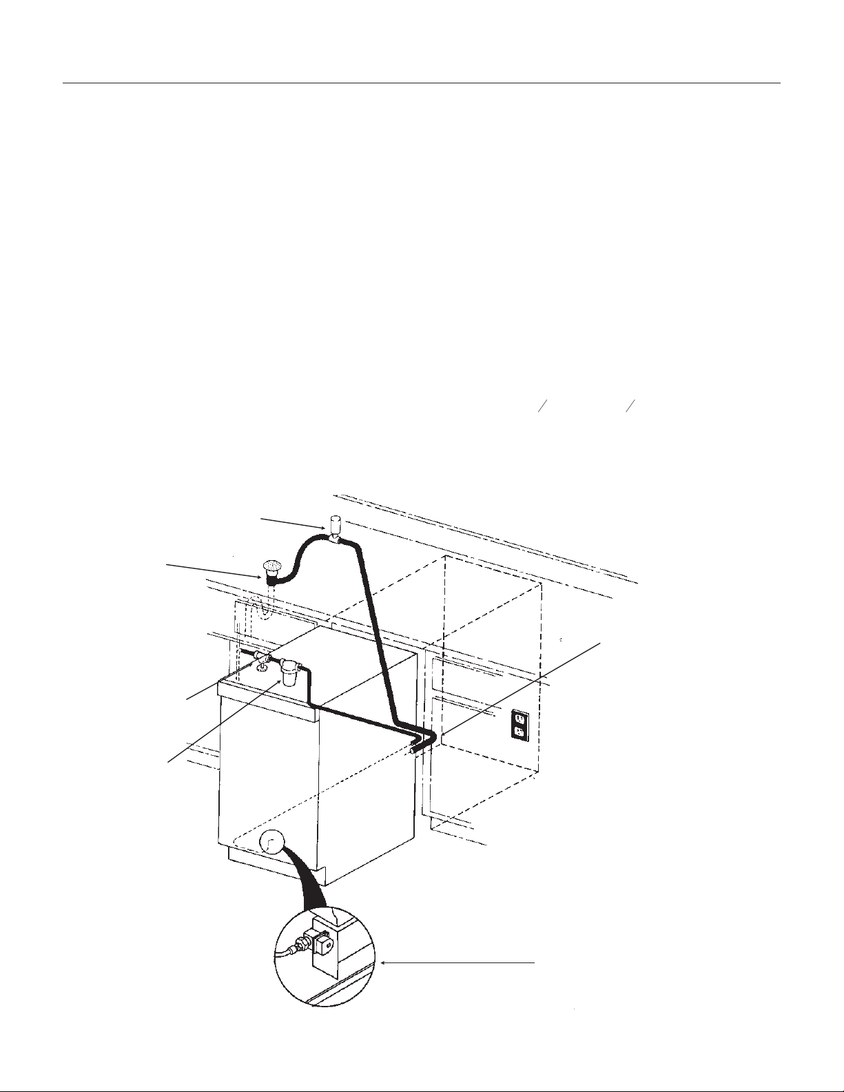
Electrical
The ice machine is supplied with a power cord. Do
not remove the grounding pin from the cord’s plug.
Do not use extension cords. Follow all codes.
Connect the machine to its own 115 volt, 15 amp
circuit.
1. If the electrical outlet for the ice maker is
behind the unit, plug in the unit.
2. Position the unit in the installation opening.
3. Turn on the water supply. Make sure that the
ice maker is plugged in and the power is on.
4. Slide unit into installation opening, paying
careful attention to water supply and drain
connections. Do not kink!
5. Pour a couple of quarts of water into the ice
storage bin; on drain pump equipped machines
the drain pump should start and water should
pump out. Check for leaks.
6. Replace the service access panel.
7. Level the unit as needed.
Installation check list:
1. Has the unit been connected to the proper
water supply?
2. Has the water supply been checked for leaks?
3. Has the unit been connected to a drain?
4. Has the drain been tested for flow and leaks?
5. Has the unit been connected to the proper
electrical supply?
6. Has the unit been leveled?
7. Have all packing materials been removed from
the machine?
8. Has the door covering been installed?
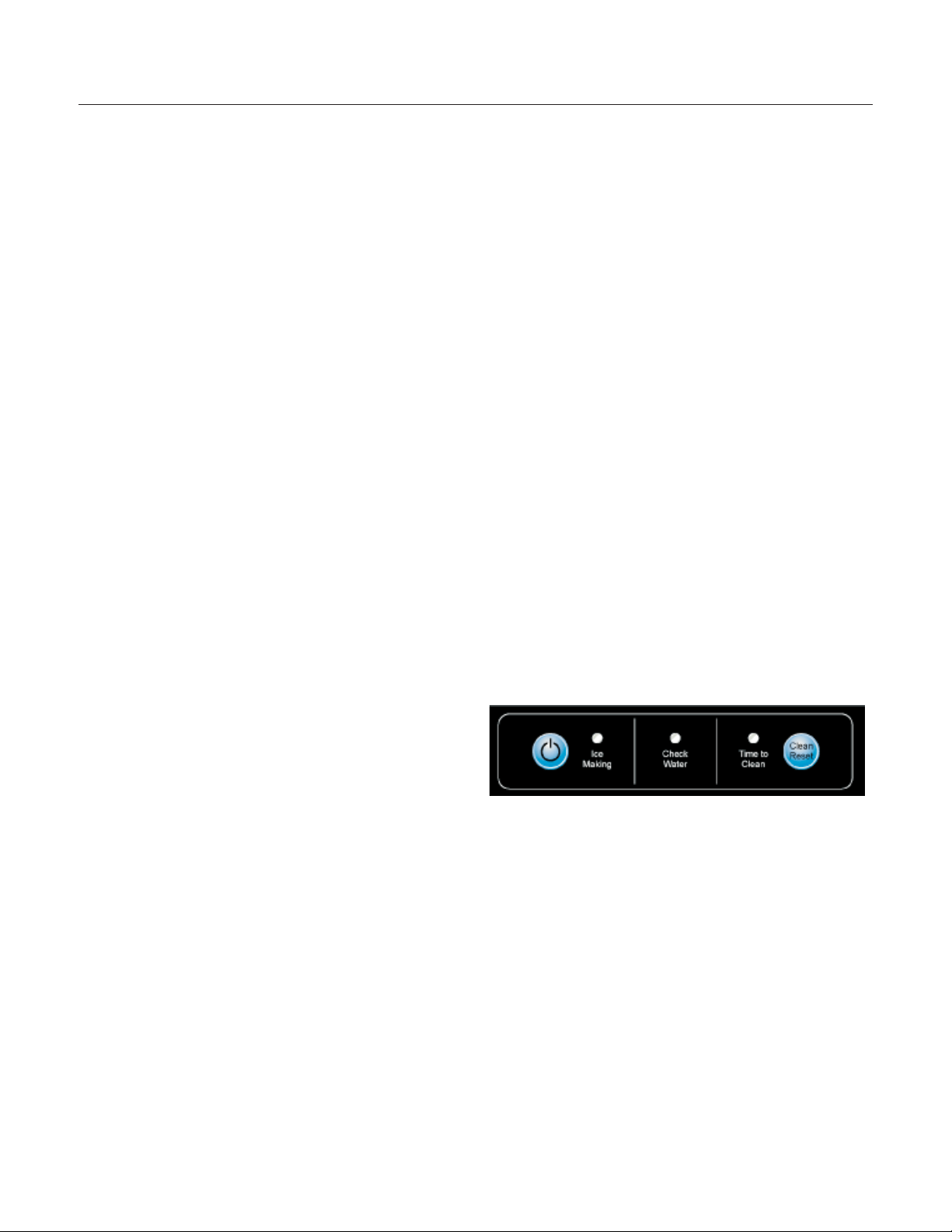
Initial Start Up
1. Turn on the water supply.
2. Switch on the electrical power.
3. Push and release the On/Off switch to start the
machine. The Ice Making light next to the
On/Off switch will glow Green.
4.
Water will begin to flow into the unit. When the
reservoir is full, water will start to drain from the
machine. After a few minutes the compressor,
water pump and fan motor will begin to operate
and the first ice making cycle will have begun.
No adjustments are needed.
After about a half hour, ice will fall into the ice
storage bin. The machine makes 24 cubes per
batch. It is normal for the first batches of ice to
melt, that continues until the bin has cooled. It will
take 8 to 10 hours of continuous run time to fill the
ice bin. When the bin is full of ice, the ice machine
will shut off. It will automatically restart when the
ice level falls, either from use or normal meltage.
July 2008
Page 11
SCCG50 & SCCP50
Installation and User's Manual
Use
No special instructions are needed for use. Just
take as much ice as you need, the machine will
replace it. A scoop is provided, and it can be stored
in the machine using the loop of tubing on the right
side as a holder. That tubing is also the ice level
sensor; ice will fill the storage bin until it's near to or
on that tube and then the machine will shut off.
The machine can be shut off anytime by just
pushing and releasing the On/Off button. The
machine will shut off at the end of the next cycle.
To shut off immediately, push and hold the On/Off
button in until the machine stops.
What shouldn’t be done?
Never keep anything in the ice storage bin that is
not ice. Objects like wine or beer bottles are not
only unsanitary, but the labels can slip off and plug
up the drain.
Never allow the machine to operate without regular
cleaning. The machine will last longer if it is kept
clean. Regular cleaning should happen at least
once per year, and preferably twice. Some water
conditions will dictate even more frequent cleaning
of the ice making section, and some carpets or
pets will dictate more frequent cleaning of the
condenser.
Note: The Time to Clean light will switch ON after 6
months of use. It will remain ON until the ice
making system is cleaned using the process on
page 13.
Noise:
The ice machine is designed for quiet operation,
but will make some noise during the ice making
cycle. During a freezing cycle, it is normal to hear
the fan moving air and the water pump circulating
water. Ice hitting the bin or ice in the bin can be
heard during harvest.
If ice making noise is objectionable, an appliance
grade timer can be added to the power supply. Set
the timer to turn the machine off at the time(s) of
day when the noise is most objectionable.
Maintenance
There are 5 things to keep clean:
1. The outside cabinet & door.
2. The ice storage bin.
3. The condenser.
4. The ice making system.
5. The ice scoop.
How to clean the cabinet.
Wipe off any spills on the surface of the door and
handle as they occur. If anything spilled on the
door or gasket dries onto the surface, wash with
soap and warm water to remove.
How to clean the ice storage bin.
The ice storage bin should be sanitized
occasionally. It is usually convenient to sanitize the
bin after the ice making system has been cleaned,
and the storage bin is empty.
A sanitizing solution can be made of 1 ounce of
household bleach and two gallons of hot (95
o
F. –
115
o
F.) water. Use a clean cloth and wipe the
interior of the ice storage bin with the sanitizing
solution, pour some of the solution down the drain.
Allow to air dry.
June 2008
Page 12
SCCG50 & SCCP50
Installation and User's Manual
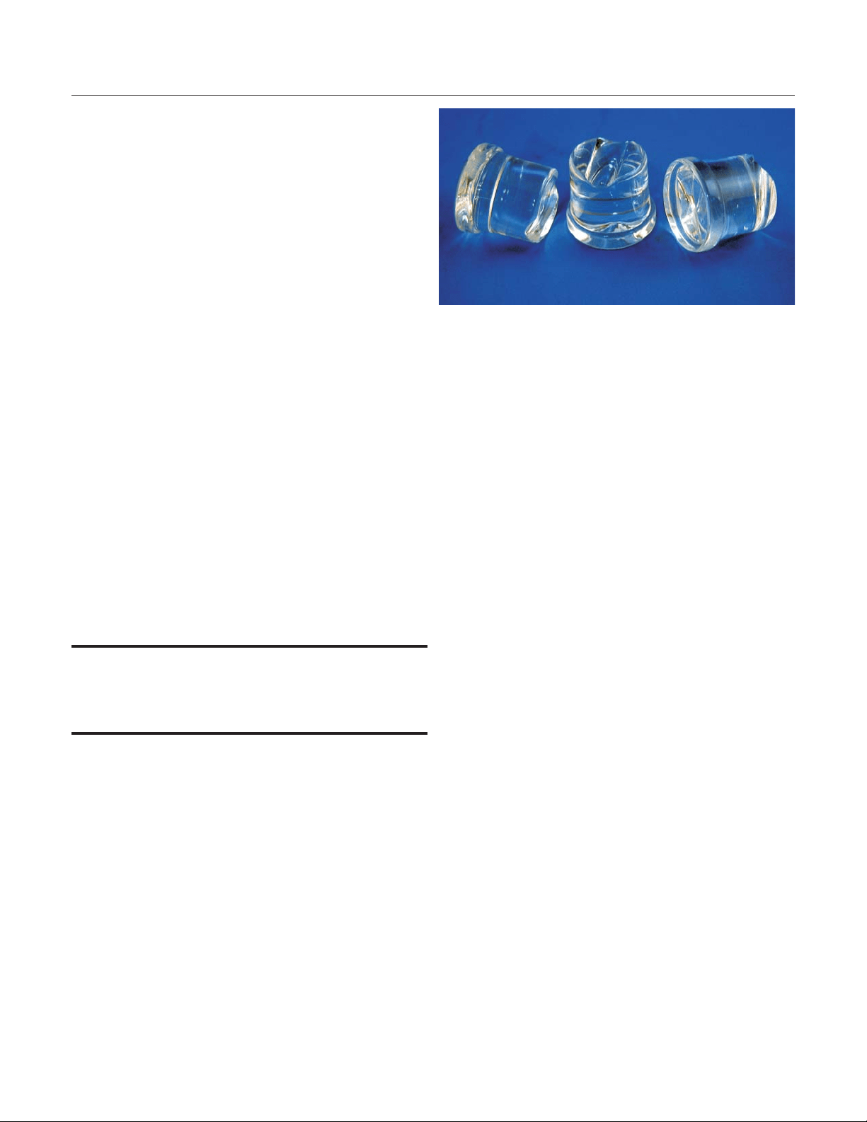
Normal cubes are tapered cylinders. If the cubes
are ragged and mis-shaped, mineral scale must be
removed from the ice making system
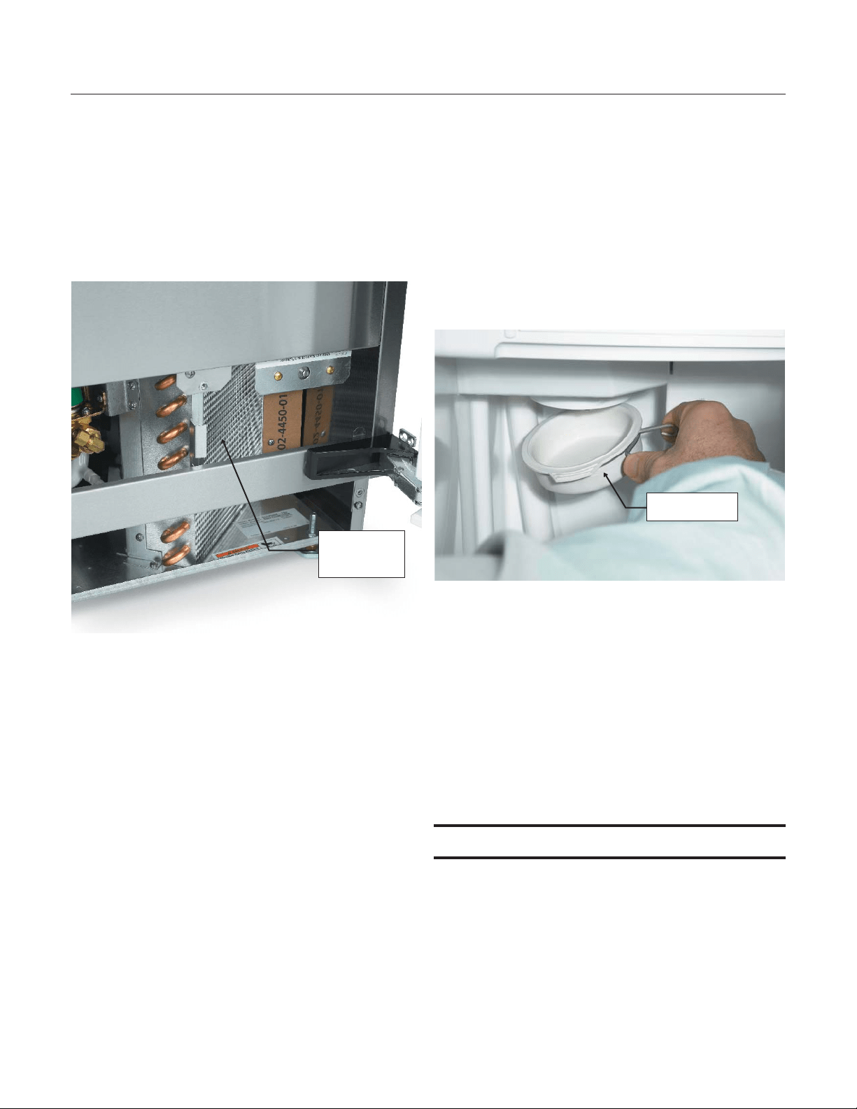
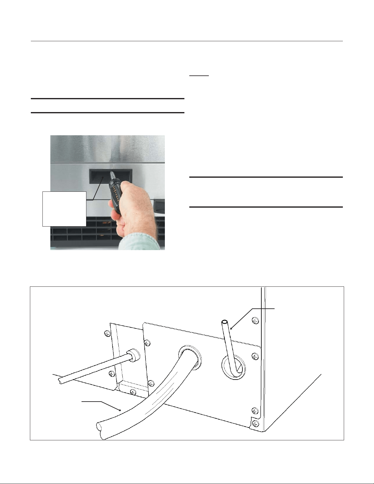
How to clean the condenser and winterize.
Condenser cleaning
The condenser is like the radiator on a car, it has
fins and tubes that can become clogged with dirt
and lint. To clean:
1. Remove the kickplate and front service panel.
2. Locate the condenser surface.
3. Vacuum the surface, removing all dust and lint.
Caution: Do not dent the fins.
4. Return the kickplate and front service panel to
their original positions. Fasten them to the cabinet
using the original screws.
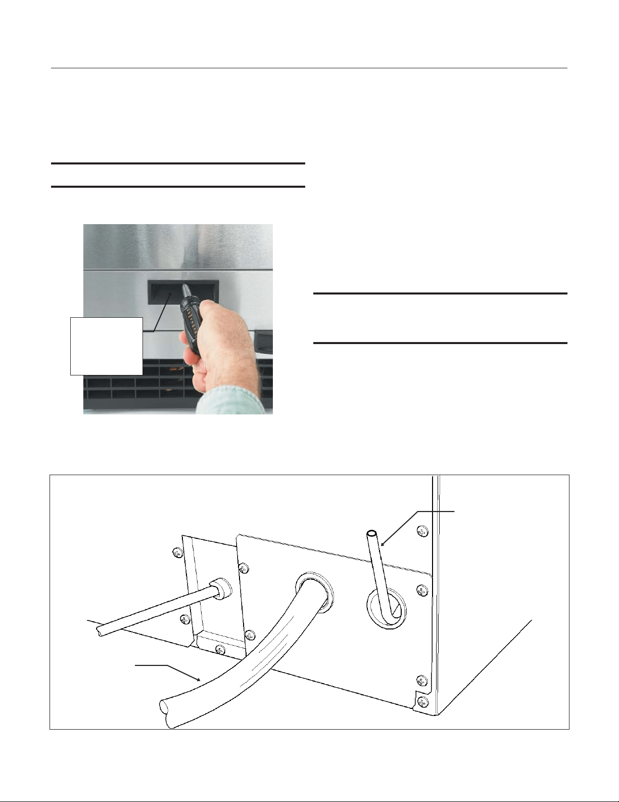
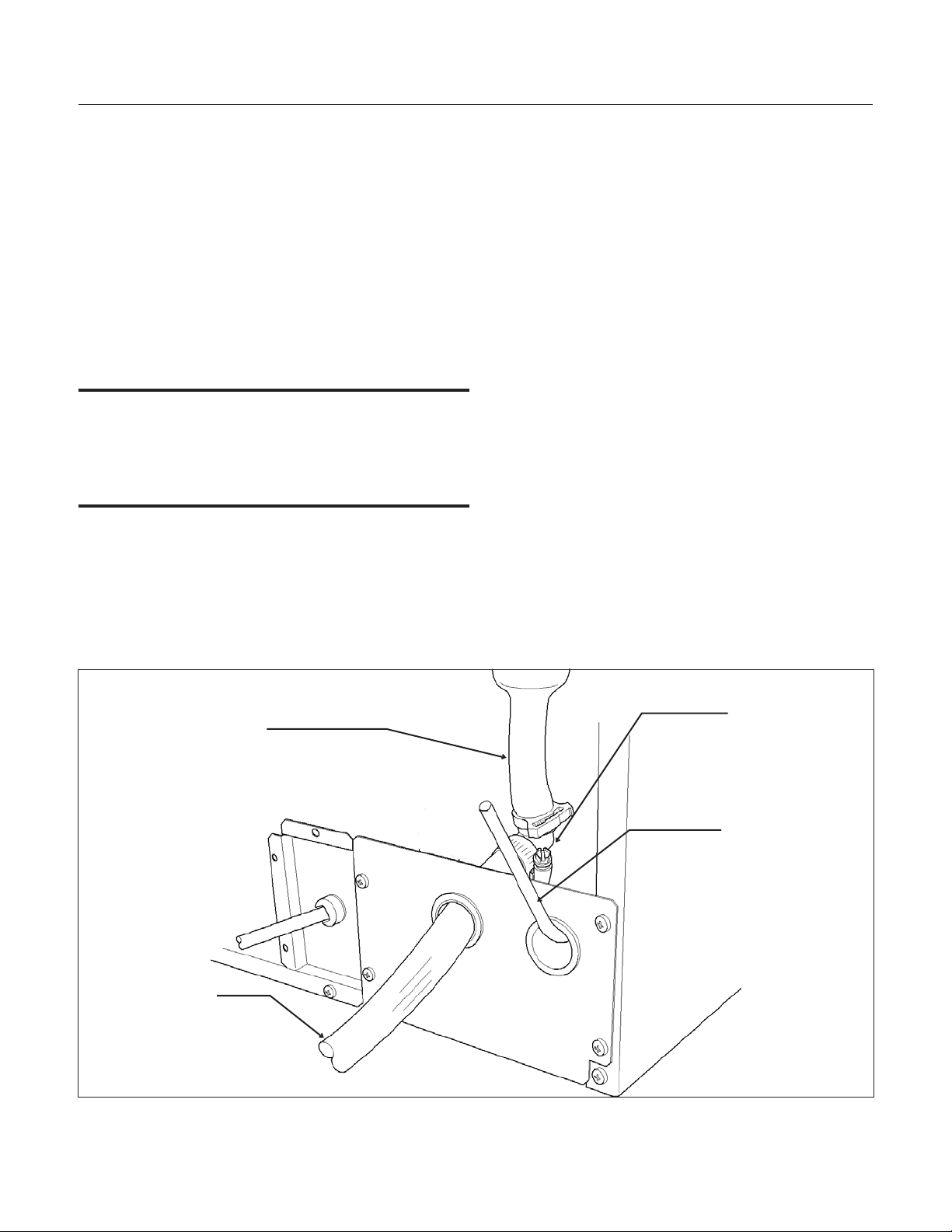
Winterizing
1. Clean the ice making system.
2. Open the door and push and release the On/Off
switch to turn the machine off.
3. Turn off the water supply.
4. Drain the water reservoir by removing the rubber
cap under the reservoir - it's near the back wall of
the ice storage bin.
5. Disconnect the incoming water line at the inlet
water valve.
6. Open the door, push and release the on/off
switch to turn the machine on.
7. Blow air through the inlet water valve; a tire
pump could do the job.
8. Drain pump models should have about 1/2
gallon of RV antifreeze (propylene glycol) poured
into the ice storage bin drain.
Note: Automotive antifreeze must NOT be used.
9. Switch off and unplug the machine.
June 2008
Page 13
SCCG50 & SCCP50
Installation and User's Manual
Rubber Cap
Condenser
Surface
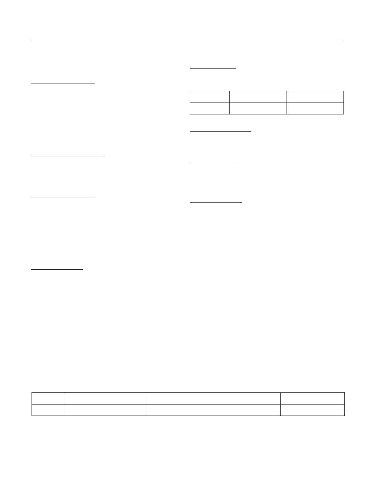
How to remove scale from the ice making system.
1. Scoop out all of the ice, either discard it or save
it in an ice chest or cooler.
2. Press and HOLD the On/Off button in for 3
seconds until the Green light goes out.
3. Press and HOLD the both the Clean-Reset and
On/Off buttons for 5 seconds. The Time to Clean
light will blink on and off.
4. Pour 4 ounces of Scotsman Ice Machine Scale
Remover (available from a local Scotsman
Distributor or Dealer) into the ice machine
reservoir.
5. Operate the machine for about ½ hour.
6. Push and release the On/Off switch. The
machine will begin to flush out the cleaning
solution.
7. Operate the machine for another ½ hour.
8. Push and release the On/Off switch. The
machine will stop the cleaning process.
9. Pour a gallon of hot (95
o
F. – 115
o
F.) water into
the bin to flush out the drain.
10. Clean the bin liner of mineral scale by mixing
some ice machine scale remover and hot water,
and using that solution to scrub the scale off of the
liner.
11. Rinse the liner with hot water.
12. Sanitize the bin interior.
13. Replace the ice removed in step 1.
14. Push and release the On/Off button to restart
ice making.
The ice scoop should be washed regularly, wash it
just like any other food container.
What to do before calling for service
Ice cubes are incompletely formed
•
Clean the ice making system
Low capacity
•
Check for restricted drain or standing water
in the bin
•
Clean the air cooled condenser fins
No ice
•
Check on-off switch
•
Check electrical breaker
•
If the Check Water light is flashing Red,
check water supply. The control system
checks for water every 20 minutes. When the
water supply is restored, the machine will
automatically restart ice making.
Time to Clean light is on
•
Clean the ice making system.
June 2008
Page 14
SCCG50 & SCCP50
Installation and User's Manual
Pour Scale
Remover Here

SCOTSMAN ICE SYSTEMS
775 Corporate Woods Parkway, Vernon Hills, IL 60061
800-533-6006
www.scotsman-ice.com
17-3191-02
Installation and
User's Manual for
Residential Ice Machine
Models SCCG30 and SCCP30

Introduction:
This ice machine is the result of Scotsman’s
decades of experience in the design and
manufacturing of both commercial and residential
ice machines.
This manual includes the information needed to
install, start up and maintain the ice machine. Note
any Caution or Warning indicators, as they provide
notice of potential hazards. Keep this manual for
future reference.
November 2009
Page 2
SCCG30 & SCCP30
User Manual
Table of Contents
Specifications .......................................... Page 3
Cabinet Layout ......................................... Page 4
Air flow ............................................. Page 5
Water Quality: .......................................... Page 6
Door Panel ........................................... Page 7
Door Panel Attachment ..................................... Page 8
Door swing change ....................................... Page 9
Water .............................................. Page 10
Gravity Drain .......................................... Page 11
Electrical ............................................ Page 12
Use ............................................... Page 13
How to clean the condenser. .................................. Page 14
Specifications
This ice machine is designed to be used indoors, in
a controlled environment. Use outside of the listed
limitations is misuse and will void the warranty.
Air temperature limits
The ice machine will operate adequately within the
limits, but functions best in temperatures between
70 and 80 degrees F.
•
Minimum – 50 degrees F
•
Maximum – 100 degrees F
Water temperature limits
•
Minimum – 40 degrees F.
•
Maximum – 100 degrees F.
Water pressure limits
•
Minimum – 20 psi
•
Maximum – 80 psi
Because the ice machine is making a food product,
the water supply to the ice machine must be
potable, or fit for human consumption.
Electrical Voltage
•
Minimum - 104 volts
•
Maximum – 126 volts
Options:
Door Panel kits
:Finished door panels are available
from Scotsman for attachment to the machine, or a
custom panel can be made.
Kit Number Panel Finish Handle Finish
KDFS Stainless Steel Stainless Steel
Kickplate Extension: In some situations the leg
levelers will be extended enough to become visible.
A kit to extend the kickplate over the legs is KKPF.
Cabinet Stability
: In some free standing
installations it may be prudent to add a bracket that
secures the back of the cabinet to a wall. That kit
number is KATB.
Drain Conversion
: A gravity drain model can be
converted to a drain pump model by installing a
drain pump kit. The drain pump kit consists of a
drain pump, wiring harness and associated tubing.
The part number is A39462-021.
Warranty Information
Warranty information is supplied separately from
this manual. Refer to it for coverage. In general, the
warranty covers defects in materials or
workmanship and does not cover corrections of
installation errors or maintenance.
November 2009
Page 3
SCCG30 & SCCP30
User Manual
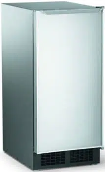
Models
•
SCCP30M-1SU – Pump model, stainless cabinet
•
SCCG30M-1SU – Gravity drain model, stainless cabinet
Cabinet Dimensions
Width Depth, w/out door panel Depth, with door panel, handle adds 1 5/8" Height
14 7/8" 22" 22 3/4" 33 3/8" to 34 3/8"
Cabinet Layout
November 2009
Page 4
SCCG30 & SCCP30
User Manual
14 7/8"
AIR IN
AIR OUT
.75
SHEET METAL DOOR FRONT
.63 MIN. CABINET DOOR
29 1/4"
1"
LEG ADJUSTMENT
(4) PLACES
33 3/8" MIN.
34 3/8" MAX.
22"
2 3/4"
4"
3 3/4"
1 1/2"
2 1/2"
3 1/4"
7 3/8"
115 V
POWER CORD
DRAIN
FLEXIBLE TUBING
3/8 I.D. PUMP MODEL (INCLUDED)
5/8 I.D. GRAVITY MODEL (NOT INCLUDED)
POTABLE WATER INLET
1/4" COMPRESSION FITTING
3 7/8"
20 3/8"
FLOOR DRAIN
ACCESS HOLE
Air flow
The machine takes in room temperature air at the
lower right front and discharges warm air from the
lower left front. Restricting the airflow will adversely
affect the ability of the ice machine to make ice.
Scotsman Ice Systems are designed and
manufactured with the highest regard for safety
and performance. They meet or exceed the
standards of agencies like U.L.
Scotsman assumes no liability or responsibility of
any kind for products manufactured by Scotsman
that have been altered in any way, including the
use of any parts and/or other components not
specifically approved by Scotsman.
Scotsman reserves the right to make design
changes and/or improvements at any time.
Specifications and designs are subject to change
without notice.
November 2009
Page 5
SCCG30 & SCCP30
User Manual
Air Intake
Warm Air Out

Water Quality:
All water, including potable water supplied by
municipalities, contains some impurities or
minerals. Water absorbs impurities from the air as
rain and/or as it flows through the ground. Some of
the impurities are solid particles, these are known
as suspended solids, and a fine particle filter will
remove them. Other impurities are chemically
bonded to the water molecules, and cannot be
filtered out, these are called dissolved solids.
Ice made by this machine will have a lower mineral
content than the water it was made from. This is
due to the method of making ice. Purer water will
freeze first in the ice making molds. The reason for
this is that anything dissolved in water lowers the
water’s freezing temperature. This concentrates
most of the impurities in the ice machine water
reservoir where they may form hard deposits
known as scale. The machine dilutes the
concentration of minerals by over-filling the
reservoir during the harvest cycle (with the excess
water flowing down the drain). About 3 quarts of
water flow into the unit each cycle. About 1 quart of
that rinses the reservoir and goes down the drain.
Some impurities will inevitably remain, and will stick
to the parts in the machine, and will cause
malformed ice cubes. Eventually, built up mineral
scale can shorten machine life.
To keep the machine operating properly, these
impurities or minerals will have to be regularly
dissolved by an acid cleaning, using Scotsman Ice
Scale Remover. Directions for this may be found in
the section under cleaning.
Filters and Treatment
In general, it is always a good idea to filter the
water. A water filter, if it is of the proper type, can
remove taste and odors as well as particles. Some
methods of water treatment for dissolved solids
include reverse osmosis, and polyphosphate
feeders. A reverse osmosis system should include
post treatment to satisfy the R.O. water’s potential
aggressiveness. Deionized water is not
recommended.
Because water softeners exchange one mineral for
another, softened water may not improve water
conditions when used with ice machines. Where
water is very hard, softened water could result in
white, mushy cubes that stick together.
If in doubt about the water, contact a local point of
use water specialist for recommendations on water
treatment.
Installation Overview
The ice machine must be connected to cold,
potable water; it must have a drain; it must be
connected to the proper power supply and must be
able circulate air through the vents at the front.
November 2009
Page 6
SCCG30 & SCCP30
User Manual
Door Panel
The ice machine is supplied without a conventional
door covering so it can be decorated to the user’s
preference. Scotsman offers several coverings
including white, black and stainless steel. In
addition, a custom built panel can be placed onto
the door.
Door Panel Attachment
To attach a Scotsman supplied panel:
Note: If door swing is to be changed, it must be
done before panel is attached.
The panel will be held on by 6 sheet metal screws
and 2 machine screws.
1. Remove the gasket and retain for later use.
2. If the door panel is stainless steel, remove any
plastic covering the stainless steel panel.
3. Place the panel onto the outside of the door,
and secure it to the door using two machine
screws, located at the left center and right
center.
4. Fasten the panel to the door using the 6 sheet
metal screws. In the hinge area, use the
outermost screw holes.
5. Place the covers over the hinge areas, and
secure each cover to the door
using a sheet metal screw.
6. Insert hole plug over screw
installed in step 5.
7. Return the gasket to its original
position.
Custom Panel
A custom panel of wood or other material not
exceeding 15 lb can be attached to the door.
Attachment is from the ice side of the door. Holes
are provided in the door for this purpose.
See instructions in information packet to create and
attach a custom panel:
November 2009
Page 7
SCCG30 & SCCP30
User Manual
Hinge Area
Cover
Door Panel Attachment
November 2009
Page 8
SCCG30 & SCCP30
User Manual
Gasket
Scotsman
Door Panel
Cover
Machine
Screw
Use Upper
Hole at the
Top
Use Lower
Hole at the
Bottom
Hole Plug
Door swing change
The door can be attached to open with hinges on
the left or right using new hinge brackets shipped
loose in the ice bin. Retain all screws for re-use.
To change:
1. Remove innermost
screw holding each
hinge to cabinet, loosen
the other.
2. Slide hinges to the side
and remove door from
cabinet. Remove
screws loosened in step
1 from both cross
braces.
3. Remove two screws securing top panel to
back, pull top panel back and remove from
cabinet.
4. Remove two screws at
the top and lift the
upper bracket out of
the cabinet. Replace
with the one supplied
loose with the machine.
Fasten it to the cabinet
using the original
screws.
5. Return the top panel to the cabinet and fasten
it with the original screws.
6. Remove kickplate and front service panel.
7. Remove two front screws and two bottom
screws holding the bottom door bracket to the
cabinet.
8. Replace the bracket with the one supplied
loose with the machine. Secure it using the
original screws.
9. Remove the upper hinge and move it to the
door's opposite side, bottom location. Secure
using the original screws.
Note: If door panel is attached, it must be removed
to access hinge screws.
10. Remove the original lower hinge and move it to
the door's opposite side, upper location.
Secure using the original screws.
11. Install a screw removed in step 2 in outermost
hole of upper and lower cross braces.
12. Attach the door to the cabinet using the original
screws.
13. Return kickplate and front service panel to their
original positions and attach to the cabinet
using the original screws.
Installation Notes
Built In Situations: If a finished floor is to be
installed in the area after the ice machine has been
built in, shims the expected thickness of the floor
should be installed under the unit to keep the
machine level with the planned floor level.
Installations on a slab: Use a pump model and
pump the water to the point of drainage. Pump
models will pump 1 story (10 feet) high.
Installations over a crawl space or basement:
Either gravity drain or pump model units may be
used, if there is not enough room behind the
machine for a drain/waste receptacle, the drain will
have to be below the floor.
Note: When installed in a corner, the door swing
may be limited due to handle contact with the wall
or cabinet face.
November 2009
Page 9
SCCG30 & SCCP30
User Manual
Screw Below
Upper
Bracket
Water
The recommended water supply tubing is ¼ inch
OD copper. Stainless steel flex or reinforced PVC
tube may also be used. Install an easily accessible
shut-off valve between the supply and the unit. This
shut-off valve should not be installed behind the
unit.
Note: Do not use self-piercing type valves.
1. Remove the front service panel.
2. Route the tubing through the right hole in the
back to the inlet water solenoid valve inlet.
3. Install a compression fitting on the tubing and
connect to the inlet of the solenoid.
Drains
There are two types of ice machine models, one
that drains by gravity and one that has an internal
drain pump.
Drain Pump Model drain installation
1. Locate the coil of 3/8” ID plastic drain tubing
secured to the back of the unit.
2. Route the plastic drain tube from the back of the
unit to the drain connection point.
IMPORTANT NOTE: Often an air gap is required by
local codes between the ice maker drain tube and
the drain receptacle.
November 2009
Page 10
SCCG30 & SCCP30
User Manual
Back View, Drain Pump Model
Water Inlet
Tube (field
supplied)
Drain Tube,
Route to
building drain
Screw
Securing
Front Service
Panel
Gravity Drain
Caution: Restrictions in the drain system to the
machine will cause water to back up into the ice
storage bin and melt the ice. Gravity drain tubing
must be vented, have no kinks and slope to the
building drain. Air gaps are typically required by
local code.
1. Place the ice machine in front of the installation
opening. Adjust leveling legs to the approximate
height.
2. Remove the front service access panel and the
upper back panel.
Note: If you are connecting a gravity drain model
and the drain opening has been located in the floor
under the base pan according to the pre install
specifications, follow steps 3 through 5 to drain the
unit through the base. If not, proceed to step 6b.
3. Remove the clamp and barbed elbow and take
off the plastic cover in the base pan below the drain
hose.
4. Connect a straight 5/8” barbed connector to the
drain hose, securing with the clamp removed in
step 4.
5. Cut an 8” piece of 5/8” ID X 7/8” OD tygon (clear
plastic) tubing. Slide one end of the tube onto the
outlet of the barbed connector and secure with a
clamp. Leave the other end of the tube lying on the
floor of the base pan until the unit is positioned
over the floor drain.
6. Route the drain tube. Either a) Insert the drain
tube through the base pan into the floor drain or b)
Route the drain tube through the left hole in the
lower back panel and connect to barbed elbow and
secure with a clamp.
7. Reinstall the upper back panel.
8. Reinstall the service access panel. Level the
unit.
IMPORTANT NOTE: Often an air gap is required by
local codes between the ice maker drain tube and
the drain receptacle.
November 2009
Page 11
SCCG30 & SCCP30
User Manual
Back View, Gravity Drain Model
Water Inlet
Tube (field
supplied)
Drain Hose
Barbed Elbow
Drain Hose,
Route to
building drain

Electrical
The ice machine is supplied with a power cord. Do
not remove the grounding pin from the cord’s plug.
Do not use extension cords. Follow all codes.
Connect the machine to its own 115 volt, 15 amp
circuit.
1. If the electrical outlet for the ice maker is behind
the unit, plug in the unit.
2. Position the unit in the installation opening.
3. Turn on the water supply. Make sure that the ice
maker is plugged in and the power is on.
4. Slide unit into installation opening, paying careful
attention to water supply and drain connections. Do
not kink!
5. Pour a couple of quarts of water into the ice
storage bin; on units equipped with a drain pump
the drain pump should start and water should pump
out. Check for leaks and proper draining.
6. Replace the service access panel. Level the unit
as needed.
Installation check list:
Has the unit been connected to the proper water
supply?
Has the water supply be checked for leaks?
Has the unit been connected to a drain?
Has the drain been tested for flow and leaks?
Has the unit been connected to the proper
electrical supply?
Has the unit been leveled?
Have all packing materials been removed from the
machine?
Has the door covering been installed?
Initial Start Up
1. Turn on the water supply.
2. Switch on the electrical power.
3. Switch the on/off switch to On.
The compressor will start and water will begin to
flow into the unit. When the reservoir is full, water
will start to drain from the machine. After a few
minutes the water pump and fan motor will begin to
operate and the first ice making cycle will have
begun.
No adjustments are needed.
After about a half hour, ice will fall into the ice
storage bin. The first batches of ice will melt, this is
normal. It will take 24 to 36 hours of continuous run
time to fill the ice storage bin. When the bin is full of
ice, the ice machine will shut off. It will
automatically restart when the ice level falls, either
from use or meltage.
November 2009
Page 12
SCCG30 & SCCP30
User Manual

Use
No special instructions are needed for use. Just
take as much ice as you need, the machine will
replace it. A scoop is provided, and it can be stored
in the machine using the loop of tubing on the right
side as a holder.
What shouldn’t be done?
Never keep anything in the ice storage bin that is
not ice; objects like wine or beer bottles are not
only unsanitary, but the labels may slip off and plug
up the drain.
Never allow the machine to operate without regular
cleaning. The machine will last longer if it is kept
clean. Regular cleaning should happen at least
once per year, and preferably twice. Some water
conditions will dictate even more frequent cleaning
of the ice making section, and some carpets or
pets will dictate more frequent cleaning of the
condenser.
Noise:
The ice machine is designed for quite operation,
but will make some noise during the ice making
cycle. It is normal to hear the fan and circulating
water during the freeze cycle, and ice hitting the bin
or ice in the bin can be heard during harvest.
If ice making noise is objectionable, a timer can be
added to the power supply. Set the timer to turn the
machine off at the time of day when the noise is
most objectionable.
Maintenance
There are 5 things to keep clean:
1. The outside cabinet & door.
2. The ice storage bin.
3. The condenser.
4. The ice making system.
5. The ice scoop.
How to clean the cabinet.
Wipe off any spills on the surface of the door and
handle as they occur. If anything spilled on the
door or gasket dries onto the surface, wash with
soap and warm water to remove.
How to clean the ice storage bin.
The ice storage bin should be sanitized
occasionally. It is usually convenient to sanitize the
bin after the ice making system has been cleaned,
and the storage bin is empty.
A sanitizing solution can be made of 1 ounce of
household bleach and two gallons of hot (95
o
F. –
115
o
F.) water. Use a clean cloth and wipe the
interior of the ice storage bin with the sanitizing
solution, pour some of the solution down the drain.
Allow to air dry.
November 2009
Page 13
SCCG30 & SCCP30
User Manual

How to clean the condenser.
The condenser is like the radiator on a car, it has
fins and tubes that can become clogged. To clean:
1. Remove the kickplate.
2. Locate the condenser surface.
3. Vacuum the surface, removing all dust and lint.
Caution: Do not dent the fins.
4. Replace the kickplate.
Winterizing
1. Clean the machine as explained on the next
page.
2. Open the door and switch the machine off.
3. Turn off the water supply.
4. Drain the water reservoir by removing the rubber
cap on the back wall of the ice storage bin.
5. Disconnect the incoming water line at the inlet
water valve.
6. Switch the machine to On.
7. Blow air through the inlet water valve until water
stops flowing from it; a tire pump could do the job.
8. Drain pump models should have about 1/2
gallon of RV antifreeze (propylene glycol) poured
into the ice storage bin drain.
Note: Automotive antifreeze must NOT be used.
9. Switch off and unplug the machine.
How to clean the ice making system
.
1. Scoop out all of the ice, either discard it or save
it in a ice chest or cooler.
2. Pour 8 ounces of Scotsman Ice Machine Scale
Remover (available from a local Scotsman
Distributor or Dealer) into the ice machine
reservoir.
3. Allow the machine to operate for about 2 hours.
4. Pour hot (95
o
F. – 115
o
F.) water into the bin to
melt the ice that has formed. That ice will likely be
white and frosty looking.
5. Clean the bin liner of mineral scale by mixing
some ice machine scale remover with hot water,
and using that solution to scrub the scale off of the
liner.
6. Rinse the liner with hot water.
7. Sanitize the bin interior.
8. Replace the ice removed in step 2.
The ice scoop should be washed regularly, wash it
just like any other food container.
What to do before calling for service
Ice cubes are incompletely formed
•
Clean the ice making system
Low capacity
•
Check for restricted drain or standing water
in the bin
•
Clean the air cooled condenser fins
No ice
•
Check on-off switch
•
Check electrical breaker
•
Check water supply
November 2009
Page 14
SCCG30 & SCCP30
User Manual

SCOTSMAN ICE SYSTEMS
775 Corporate Woods Parkway, Vernon Hills, IL 60061
800-533-6006
www.scotsman-ice.com
17-3191-01
User's Manual
for Residential Ice Machine
Model
DCE33

INTRODUCTION
The Scotsman DCE33 is a restaurant type ice
machine designed for home use. It produces the
same high quality ice as large Scotsman
commercial ice cube machines, and stores that ice
in a heavily insulated storage bin.
Table of Contents
Parts lists and wiring diagrams are located in the
center of the manual.
DCE33
September 2011
Page 1
This service manual is intended as a resource for
people installing, using, and servicing the DCE33.
Because it contains information on safety and
maintenance, Scotsman strongly recommends that
this manual be kept where it is readily available.
TECHNICAL INFORMATION ··································· Page 2
CABINET DIMENSIONS ····································· Page 3
INSTALLATION ·········································· Page 4
TO INSTALL: Plumbing ······································ Page 5
TO INSTALL: Plumbing ······································ Page 6
TO INSTALL: Plumbing ······································ Page 7
TO INSTALL: Plumbing ······································ Page 8
TO INSTALL: Plumbing ······································ Page 9
TO INSTALL: Add On Kits ···································· Page 10
TO INSTALL: Add On Kits ···································· Page 11
AFTER INSTALLATION ····································· Page 12
AFTER INSTALLATION - OPERATION ····························· Page 13
OPERATION ··········································· Page 14
COMPONENT LOCATION ···································· Page 15
MAINTENANCE AND CLEANING ································ Page 16
CLEANING ············································ Page 17
ADJUSTMENTS ········································· Page 18
ADJUSTMENTS ········································· Page 19
HARVEST TIME ADJUSTMENT, models DCE33A-1BD, DCE33PA-1BD, DCE33A-1SSD or
DCE33PA-1SSD ········································· Page 20
SERVICE DIAGNOSIS ······································ Page 21
SERVICE DIAGNOSIS ······································ Page 22
REPAIR·············································· Page 23
REPAIR·············································· Page 24
REPAIR·············································· Page 25
REPAIR·············································· Page 26
TECHNICAL INFORMATION
Scotsman Ice Systems are designed and
manufactured with the highest regard for safety
and performance. They meet or exceed the
standards of U.L., and C.U.L.
Scotsman assumes no liability or responsibility of
any kind for products manufactured by Scotsman
that have been altered in any way, including the
use of any parts and/or other components not
specifically approved by Scotsman.
Scotsman reserves the right to make design
changes and/or improvements at any time.
Specifications and designs are subject to change
without notice.
DCE33
April 2013
Page 2
Serial Number
Tag Location
Cool Air In
Warm Air Out
Model Number Basic
Electrical
Maximum
Fuse Size
Cabinet
Color
Drain
Pump?
DCE33A-1WB 115/60/1 15 amp White No
DCE33PA-1WB 115/60/1 15 amp White Yes
DCE33A-1BB 115/60/1 15 amp Black No
DCE33PA-1BB 115/60/1 15 amp Black Yes
DCE33A-1SB 115/60/1 15 amp Black
with SS
door
No
DCE33PA-1SB 115/60/1 15 amp same Yes
DCE33A-1WC 115/60/1 15 amp White No
DCE33PA-1WC 115/60/1 15 amp White Yes
DCE33A-1BC 115/60/1 15 amp Black No
DCE33PA-1BC 115/60/1 15 amp Black Yes
DCE33A-1SC 115/60/1 15 amp Black
with SS
door
No
DCE33PA-1SC 115/60/1 15 amp same Yes
DCE33A-1BD 115/60/1 15 amp Black No
DCE33PA-1BD 115/60/1 15 amp Black Yes
DCE33A-1SSD 115/60/1 15 amp Stainless
Steel
No
DCE33PA-1SSD 115/60/1 15 amp same Yes
Add On Kits: Stainless Steel Door Panel Kit is SS33
Cabinet Extensions: KCE18-SS (Stainless Steel) KCE18-B
(black)
Stainless steel door sleeve conversion kit is K-SS
Drain Pump Kit to convert gravity drain to pump drain, see
page 10.
Refrigerant Charge is 5 ounces of R-134a. Compressor HP
is 1/8
D series utilizes an electronic harvest timer. All others
equipped with mechanical timer.
CABINET DIMENSIONS
DCE33
September 2011
Page 3
Overhead View of DCE33 and
Companion Refrigerator Side By
Refrig.
Ice
Machine
DCE33 Cabinet Views
Pump Drain Hose is 3/8"
ID

INSTALLATION
To properly make and store ice, the DCE33
requires access to air, potable water, 115 volt
electricity and a drain. The machine must be
installed indoors, in a controlled environment.
Air: The ice machine uses a fan to take in room air
at the front of the machine through the right side of
the kick plate. It discharges warm air out the left
side of the kick plate. Anything placed in front of
the kick plate will restrict air flow and cause a
decrease in performance and efficiency. The
minimum air temperature the machine will operate
in is 50
0
F., and the maximum is 100
0
F.
Water Supply: The ice machine requires a
continuous supply of potable water at no less than
20 p.s.i.g. of flowing pressure. Static water
pressure should not exceed 80 p.s.i.g. The
minimum water temperature the machine will
operate in is 40
0
F., and the maximum is 100
0
F.
Water Quality:
There is no such thing as “pure” water; all water,
including potable water supplied by municipalities,
contains some “impurities”. Water absorbs
impurities from the air as rain and/or as it flows
through the ground. Some of the impurities are
solid particles, these are known as suspended
solids, and a fine particle filter will remove them.
Other impurities are chemically bonded to the
water molecules, and cannot be filtered out, these
are called dissolved solids.
Ice made by the DCE33 will have a lower
mineral content than the water it was made from.
Purer water will freeze first in the ice making
molds. The reason for this is that anything
dissolved in water lowers the water’s freezing
temperature.
This concentrates most of the impurities in the ice
machine water reservoir where they may form hard
deposits known as scale. The DCE33 dilutes the
concentration of minerals by over-filling the
reservoir during the harvest cycle (with the excess
water flowing down the drain). About 3 quarts of
water flow into the unit each cycle. About 1 quart
of that rinses the reservoir and goes down the
drain.
Some impurities will inevitably remain, and will
stick to the parts in the machine, and will cause
malformed ice cubes. Eventually, built up mineral
scale can shorten machine life.
To keep the machine operating properly, these
impurities or minerals will have to be regularly
dissolved by an acid cleaning, using Scotsman Ice
Machine Cleaner. Directions for this may be found
in the section under cleaning.
In general, it is always a good idea to filter the
water. A water filter, if it is of the proper type, can
remove taste and odors as well as particles. Some
methods of water treatment for dissolved solids
include reverse osmosis, and polyphosphate
feeders. A reverse osmosis system should include
post treatment to satisfy the R.O. water’s
“aggressiveness”.
Deionized water is not recommended.
Because water softeners exchange one mineral for
another, Scotsman does not recommend their use
for ice machines. Where water is very hard,
softened water may result in white, mushy cubes
that stick together.
Scotsman suggests, that if in doubt about the
water, that a local point of use water specialist be
contacted for recommendations on water
treatment.
Electricity: The machine is supplied with a cord,
and may be plugged into a wall outlet. The ice
machine should be the only device using that
circuit.
The fuse (or circuit breaker) size should be 15
amps.
Drain: There are two DCE33 models:
The DCE33A-1 is a gravity drain model that
requires a drain tube that’s pitched down from the
outlet at the back of the cabinet to the connection
to the sanitary sewer.
The DCE33PA-1 has a built in drain pump that will
pump water up to a drain point, such as a nearby
sink.
September 2011
Page 4
DCE33
TO INSTALL: Plumbing
The water supply and drain should be roughed in
and ready at the point of installation. A wall outlet
directly behind the ice machine will make
undercounter installation easier. All electrical,
water and drain connections must conform to local
codes.
Installation Cautions: Although the DCE33 has
been designed to be serviced in place, in some
cases it may be necessary to pull the unit out for
service. For that reason do not restrict access to
the cabinet at the front - top and bottom.
If a floor is to be installed after the ice machine,
shims the thickness of the floor should be installed
under the DCE33 to keep the machine level with
the floor. Also, allow 1/8" clearance on each side of
the cabinet.
Installations on a slab: Use a pump
(DCE33PA-1) model and pump the water to the
point of drainage. Pump models will pump 1 story
high.
Installations over a crawl space or basement:
Either gravity drain or pump model units may be
used, if there is not enough room behind the
machine for a drain/waste receptacle, the drain will
have to be below the floor.
ALL PLUMBING MUST MEET LOCAL CODES
Note: When installed in a corner, the door
swing may be limited due to handle contact
with the wall or cabinet face.
DCE33
September 2011
Page 5
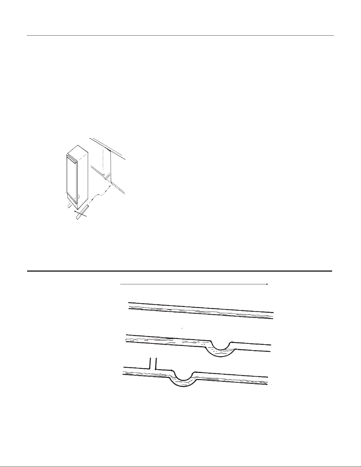
Normal Drain Line, Pitched
Down From Ice Machine
With Trap, Causes Poor Draining
With Trap And Vent,
Draining Is Normal
EXAMPLES OF GRAVITY DRAIN TUBE INSTALLATIONS
From Ice Machine
To Drain
Good Draining
Poor Draining
Good Draining
Shims
Install Unit
Flush With Floor
TO INSTALL: Plumbing
Free Standing Cabinet, Gravity Drain
Model:
All horizontal runs of drain lines must have a 1/4"
per foot fall. An air gap will likely be required
between the ice machine drain tube and the
drain/waste receptacle. A stand pipe with a trap
below it would be acceptable for the drain/waste
receptacle. A floor drain is also acceptable.
FOLLOW ALL LOCAL PLUMBING CODES
Poor draining will cause a high rate of ice
melting in the bin.
1. Remove the kick plate and the access cover
above it.
2. Route the water supply, which should be a 1/4"
O.D. copper tube through the back of the cabinet
to the front.
3. Install a flare nut and flare the end of the tube.
4. Flush the water line and fasten the flare nut to
the male flare on the inlet water valve.
5. Route a
5
8
" ID (7/8" OD) drain tube through the
back panel of the machine and connect to the bin
drain fitting at the bottom of the bin. Secure with
hose clamps.
Be certain that the drain tube is pushed up well
past the barbs on the drain fitting. If needed to
ease installation, soak the drain hose in hot water
just before connecting to the fitting.
6. Route the drain tube from the ice machine to the
drain/waste receptacle. Note: if using a long
horizontal run (more than 5’) the drain should be
vented at back of cabinet.
7. Turn on the water supply and check for leaks.
8. Replace the kick plate and the access cover
above it.
9. Level the unit using the leg levelers.
DCE33
September 2011
Page 6
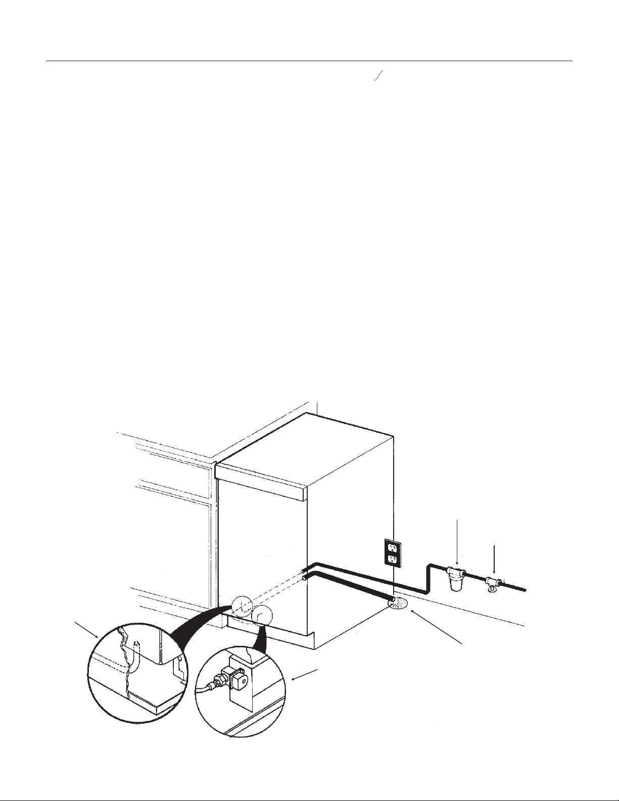
INSTALLATION OF WATER AND DRAIN
Water Inlet
Connection Detail
Drain Detail
Floor Drain
Shut Off Valve
Water Filter
(Recommended)
TO INSTALL: Plumbing
Free Standing Cabinet, Pump Model:
1. Remove the kickplate and control box cover.
2. Route the water supply, which should be a 1/4"
O.D. copper tube through the back of the cabinet
to the front.
3. Install a flare nut and flare the end of the tube.
4. Flush the water line and fasten the flare nut to
the male flare on the inlet water valve.
5. Locate the coil of 3/8" ID plastic drain tubing
secured to the back of the cabinet.
6. Route the plastic drain tubing to the drain point
connection. Do not connect to a drain/waste line
below a trap. Connect the discharge line to the
drain, per local codes. An air gap will likely be
required between the ice machine drain tube and
the drain/waste receptacle.
7. Turn on the water and plug in the ice machine.
Pour a couple quarts of water in the bin, the drain
pump should start. Check for water leaks.
8. Replace the kickplate and control box cover.
9. Level the unit using the leg levelers.
ALL PLUMBING MUST MEET LOCAL CODES
DCE33
September 2011
Page 7
Air Gap Device
(Where Required)
Drain
Connection
Water Shut
Off Valve
Water Filter
(Recommended)
Drain Tube
From Back Of
Machine
Water Inlet Connection
WATER AND DRAIN
INSTALLATION
THE DCE33 WILL FIT IN A SPACE
15
1
4
"WIDEX33
3
4
" HIGH.
THE DEPTH OF THE CABINET IS 22" TO
THE FRONT EDGE OF THE HANDLE.
TO INSTALL: Plumbing
Built In, Gravity Drain Model:
The drain and inlet water tubes must be plumbed
before connecting to the ice machine. All horizontal
runs of drain lines must have a 1/4" per foot fall. An
air gap will likely be required between the ice
machine drain tube and the drain/waste
receptacle. A stand pipe with a trap below it would
be acceptable for the drain/waste receptacle.
Note: Poor draining will cause a high rate of ice
melting in the bin.
1. Place ice machine in front of installed location.
Adjust leg levelers to approximately correct
position.
2. Remove kickplate and the access cover above
it.
3. Route water inlet line, which should be a 1/4"
O.D. copper tube, from wall through ice machine to
the front.
4. Route drain line from wall position through ice
machine. Note: if using a long horizontal run (more
than 5’) the drain should be vented at back of
cabinet.
5. If electrical outlet for ice machine is behind the
cabinet, plug in the ice machine now.
6. Push ice machine into installed position.
7. Cut off water inlet line at required length.
8. Flush water line. Place flare nut on inlet water
line and flare the end of the copper tube.
9. Attach flare nut to the male flare on the inlet
water valve.
10. Cut off the drain tube to the required length.
11. Route a
5
8
" drain tube through the back panel
of the machine and connect to the bin drain fitting
at the bottom of the bin. Secure with hose clamps.
Be certain that the drain tube is pushed up well
past the barbs on the drain fitting. If needed to
ease installation, soak the drain hose in hot water
just before connecting to the fitting.
12. Turn on the water supply and check for leaks.
13. Replace the kickplate and the access cover
above it. Level as needed.
ALL PLUMBING MUST MEET LOCAL CODES
DCE33
September 2011
Page 8
INSTALLATION OF WATER
AND DRAIN
Water Inlet Connection
Detail
Drain
Connection
Shut Off Valve
Water Filter
(Recommended)
TO INSTALL: Plumbing
Built In Pump Model:
1. Place ice machine in front of installed location.
Adjust leg levelers to approximately correct
position.
2. Remove kickplate and control box cover.
3. Route water inlet line from wall through ice
machine to the front.
4. Locate coil of 3/8" ID plastic drain tubing
secured to the back of the cabinet.
5. Route plastic drain tube from back of cabinet to
drain connection point.
Note: Often an air gap is required by local codes
between the ice machine drain tube and the drain
receptacle.
6. If electrical outlet for ice machine is behind the
cabinet, plug in the ice machine now.
7. Push ice machine into installed position.
8. Cut off water inlet line at required length.
9. Flush water line. Place flare nut on inlet water
line and flare the end of the copper tube.
10. Attach flare nut to the male flare on the inlet
water valve.
11. Turn on the water supply, and make sure that
the ice machine is plugged in and the power is on.
12. Pour a couple of quarts of water into the
storage bin, the drain pump should start and pump
water out. Check for leaks.
13. Replace kickplate and control box cover.
14. Level the cabinet as needed.
ALL PLUMBING MUST MEET LOCAL CODES
DCE33
September 2011
Page 9
THE DCE33 WILL FIT IN A SPACE 15
1
4
"WIDEX33
3
4
" HIGH.
THE DEPTH OF THE CABINET IS 22" TO
THE FRONT EDGE OF THE HANDLE.
Air Gap Device
(Where Required)
Drain
Connection
Water Shut Off
Valve
Water Filter
(Recommended)
Drain Tube From
Back Of Machine
Water Inlet Connection
WATER AND DRAIN
INSTALLATION
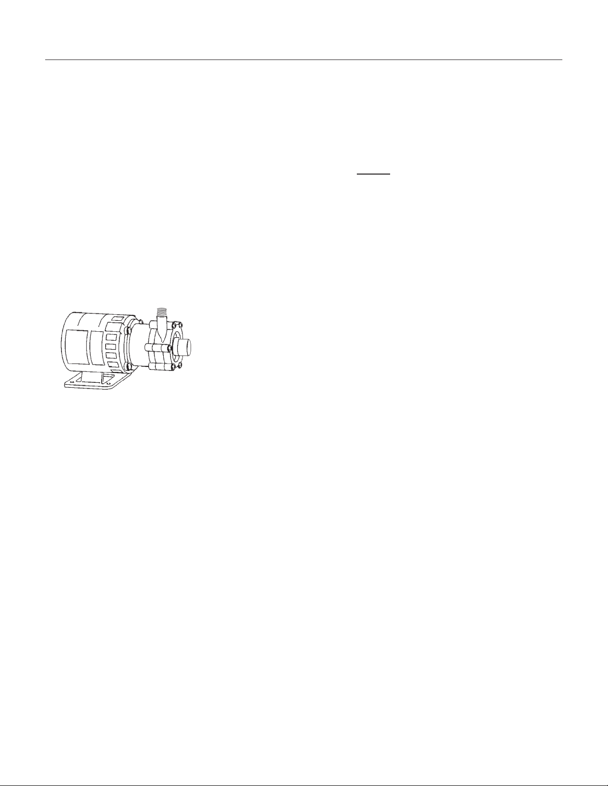
TO INSTALL: Add On Kits
Drain Pump Kit
The DCE33 is delivered either with or without a
drain pump. Models without a drain pump drain
their water by gravity. However, gravity drain
models may be converted to Pump models thru the
installation of a Drain Pump Kit and Drain Pump.
Two parts are required for this conversion:
Drain pump kit part number........A36892-020 (all except
DCE33A-1BD or DCE33A-1SSD)
Drain pump kit part number.................A39885-001 for DCE33A-1BD or DCE33A-1SSD
Drain pump part number..........12-2503-21
Specific step-by-step instructions are included with
the kit.
DCE33
April 2013
Page 10
Drain Pump
TO INSTALL: Add On Kits
Door Kit: The door may be modified to accept a
decorator door panel.
Customizing Door Panel:
A custom door panel may be installed in front of
the standard one. Any panel 14
3
4
" wide, 28
15
16
"
high and
1
4
" thick or less at the edges may be used
as a decorator panel. Examples of decorator
panels include wood to match the adjacent
cabinets; metal of different colors to match nearby
appliances; or just about any material that will fit.
Scotsman has a stainless steel panel available to
fit this machine, the kit number is SS33.
If the material is less than 1/4" thick, the space
between the new panel and the original may be
filled with cardboard.
1. Remove single screw and the left
hand hinge filler plate from the top of the
door.
2. Remove two screws from the top of
the door and lift off the door handle.
3. Open the door slightly, about one-third
or so; then, remove the front screw
holding the hinge to the door.
4. Loosen the rear screw of the hinge
just enough to allow the door to sag or
move forward. This will allow access to
the top of the channels at the right and
left edges of the door.
5. From the top of the door, insert the
decorator panel (pre-cut) evenly into the
channels; carefully slide the panel all the
way down until the panel is fully into the
bottom channel.
6. Check that the panel is the in all the
way and does not protrude past the top
edge of the door.
7. Push the top hinge corner of the door
IN to align screw hole in the hinge with
the screw hole in the door. Install the
screw previously removed. Tighten the
other screw.
8. Replace the door handle and filler
plate; secure with screws previously
removed.
DCE33
September 2011
Page 11
Custom Panel,
Thin Panel
Shown With Filler
Hinge
Door With
Groove
Door Handle
Hinge
Filler Plate
Parts Involved in Customizing Door Panel
DCE33
September 2011
Page 12
AFTER INSTALLATION
Reversing Door Swing:
The hinged side of the door may be reversed to
the other side if desired:
The DCE33 was shipped with the door hinged at
the right. The door and hinges are designed for
placing the hinges on either the right or the left
side of the cabinet. Moving the hinges to the left
allows the door to pivot from the left side.
Note: There is a part, packed with the machine,
that is required for this procedure.
1. Open the door and remove the three screws
holding the lower hinge to the cabinet.
2. With the door open enough to see both
screws at the top door hinge, remove the two
screws. The door is now free of the cabinet.
3. Remove the single screw and the hinge
filler plate from the top of the door.
4. Install the other filler plate (shipped inside
refrigerator compartment) onto the top corner
of the door where the hinge was.
5. Remove the three plastic plugs from the
top front corner where the hinge will mount.
6. Remove the three plastic plugs from the
lower front corner where that hinge will
mount.
7. Remove the three screws holding the top
hinge to the cabinet. Remove that hinge from
the top and, flipping it upside down, install it
onto the bottom of the door, on the opposite
side using the original screws.
8. Remove the hinge assembly from the
bottom of the door, and flip it upside down;
secure it to the cabinet at the opposite side
top position with the original screws.
9. Hold the door up to the cabinet. Secure
the door to the top hinge with the original
screws.
10. Secure the bottom hinge to the cabinet
with the original screws.
11. Place the plastic plugs removed earlier
into the empty holes.
12. Check operation of the door by opening
and closing it.
Hinge
Filler Plate
Door Handle
Door
Magnetic
Gasket
Hinge
Reverse Hinges From Top to Bottom and
Left to Right to Reverse Door Swing

AFTER INSTALLATION - OPERATION
Final Check List
1. Has the machine been properly uncrated, and
have all packing materials and tape been removed
from inside the bin?
2. Have the installation instructions been followed,
including connecting the machine to water, drain
and electricity?
3. Has the machine been leveled?
Initial Start Up - DCE33A-1BD,
DCE33PA-1BD, DCE33A-1SSD or
DCE33PA-1SSD
1. Turn on water supply.
2. With unit plugged in, rotate ice machine control
knob to the ON position.
3. Allow the unit to operate for 1 hour, and check
the size of the cubes, if they are not correct, adjust
as recommended on page 18.
4. After the cubes are confirmed to be the correct
size, replace all panels.
5. Locate the nameplate on the control box cover.
Record the serial number and date of start up here
in the manual. Keep the manual handy for future
reference.
Serial Number:___________________________
Date of initial start up:_____________________
6. Fill out and mail the Warranty Registration.
How To Use:
The ice machine is extremely simple to use, just
turn the ice machine control knob to the on
position. The DCE33 will automatically begin to
freeze ice and will continue to do so until the bin is
full. A new machine, warm out of the box, could
take as long as 48 hours to fill and shut off.
Use the scoop to remove ice and place the ice
scoop in the holder provided (do not leave the
scoop on the ice, as it will gradually disappear into
the ice).
What to expect from the DCE33
The DCE33 will release a batch of 8 ice cubes
about every 30 minutes. At the same time the
cubes fall into the storage bin, water will be
entering the ice machine and draining out.
Ice: The ice cubes are tapered cylinders about 1
1
4
"
in diameter at the widest end; taper down to 1"
wide at the top; and are 1
1
8
" high. When the
machine is adjusted properly, there should be a
1
4
"
indent in the base of the cube. The ice will appear
wet when fresh, this is normal. It may also develop
frost on the outside and look cloudy - this is also
normal (the frost will disappear when liquid is
poured over the ice).
Storage: All restaurant type ice machine operate
on this principal: The ice storage bin is not
refrigerated; instead it’s heavily insulated, much
like a picnic cooler or ice chest. If the ice bin were
to be refrigerated, the ice would freeze together
into one very large cluster of ice, and would begin
to evaporate. This would yield ice that is very poor
in quality, and difficult to remove from the machine.
The DCE33 will continue to operate until ice builds
up high enough to contact the bin thermostat
sensor tube, then it will shut off. Models with a
drain pump will occasionally pump out melt water
when the machine is off. The pump will only be on
for a few seconds.
Run Time: The amount of time the DCE33 will run
to replace melted ice is about 6 hours per day. The
amount of time the ice machine will run to replace
ice removed is dependent upon how much is
removed, how clean the ice machine is, and how
hot the air and water supplied to the machine are.
A machine that has been emptied will usually take
about 24-36 hours to re-fill.
DCE33
April 2013
Page 13
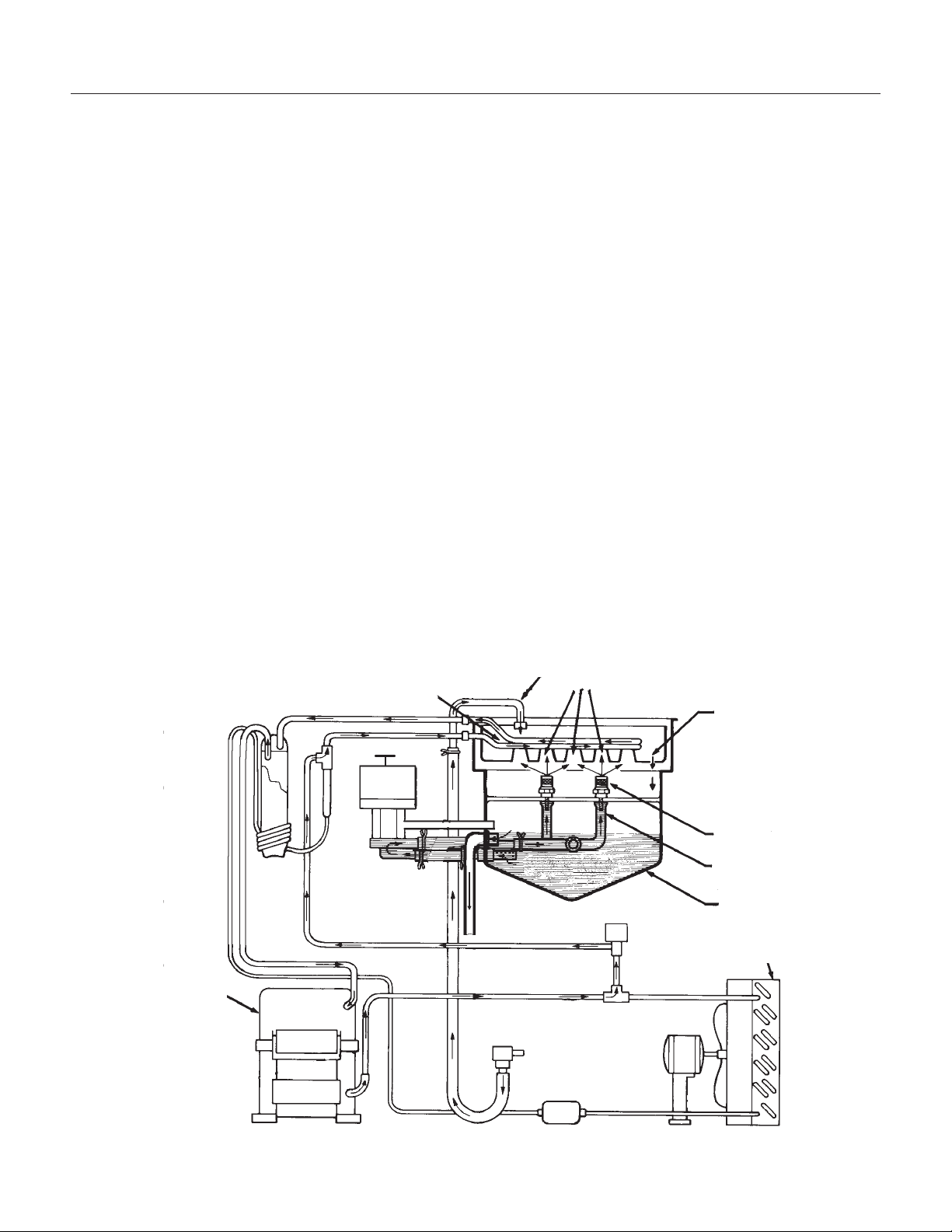
OPERATION
How does the machine make ice?
There are two distinct cycles: freeze and harvest.
1 freeze cycle + 1 harvest cycle = 1 batch of 8
cubes.
The Freeze cycle happens when water is sprayed
against the freezing surface. The Harvest cycle is
when the ice is released and water enters the
machine. A complete cycle takes about 30
minutes.
Freeze: During the freeze cycle the compressor is
pumping refrigerant, the fan motor is blowing air,
and the water pump is circulating water. As the
refrigerated surface absorbs heat from the water
sprayed against it, that heat is moved to the area
where the fan is blowing air. The heat is
transferred to the air, and the warmed up air is
discharged from the ice machine. At the same time
ice is forming on the refrigerated surface (located
at the upper back of the machine). When the
refrigerated surface gets cold enough, the ice
machine’s timer will start. After a few minutes the
timer will stop the freeze cycle and begin the
harvest.
Harvest: During the harvest cycle the compressor
is still operating, but the spray pump and fan motor
have stopped. Two other components have been
energized; the hot gas valve and the inlet water
valve. These two valves open and warm up the
freezing surface, allowing the cubes to fall into the
bin. The timer is still turning, and when it gets to
the end of the harvest cycle, the freeze cycle will
restart.
How does the machine use water? The ice
machine begins with a fixed charge of water that is
contained in the reservoir. As the water is sprayed
against the freezing surface, the part of water that
does not contain mineral impurities will freeze and
stick to the ice cup molds. The water containing
impurities falls back into the reservoir. Gradually,
during the freezing portion of the ice making cycle,
the water in the reservoir will become highly
concentrated with mineral impurities.
During the harvest cycle fresh water flows into the
machine to dilute the reservoir water and to rinse
the concentrated minerals down the drain.
DCE33
September 2011
Page 14
Cube Molds
Spray Jets
Water Tube
Reservoir
Condenser
Weep
Hole
Compressor
Evaporator
Water
Inlet
Schematic Diagram - Shown In
Harvest Cycle
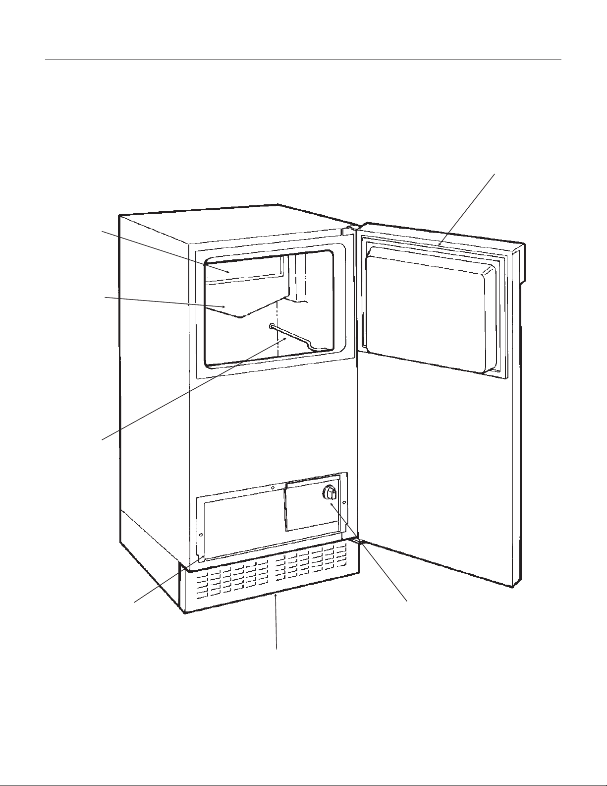
COMPONENT LOCATION
DCE33
September 2011
Page 15
Reservoir
Curtain
Bin
Thermostat
Bracket
Control Box
Cover
Kickplate
Control Knob
Door Gasket
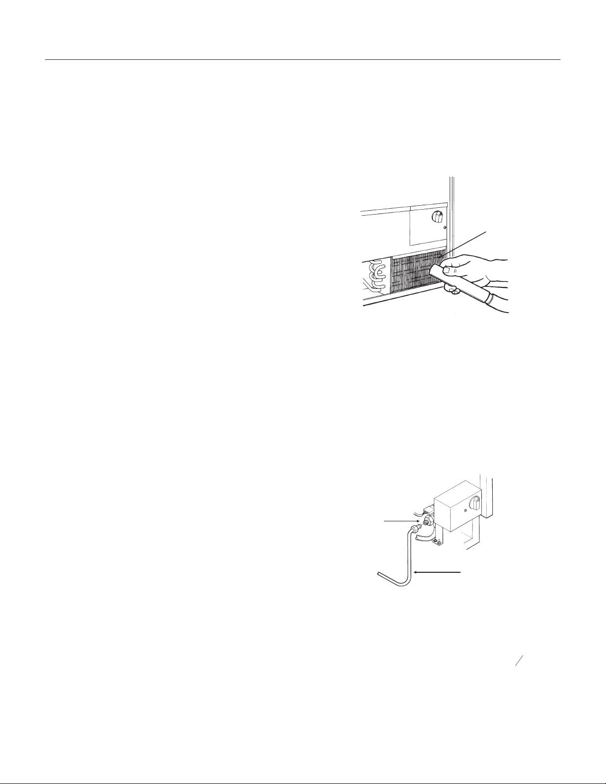
MAINTENANCE AND CLEANING
What shouldn’t be done?
Never keep anything in the ice storage bin that is
not ice; objects like wine or beer bottles are not
only unsanitary, but the labels may slip off and plug
up the drain.
Never allow the machine to operate without regular
cleaning. The machine will last longer if it is kept
clean. Regular cleaning should happen at least
once per year, and preferably twice. Some water
conditions will dictate even more frequent cleaning
of the ice making section, and some carpets or
pets will dictate more frequent cleaning of the
condenser.
What should be kept clean?
There are 5 things to keep clean:
1. The outside cabinet & door.
2. The ice storage bin.
3. The condenser.
4. The ice making system.
5. The ice scoop.
How to clean the cabinet.
Wipe off any spills on the surface of the door and
handle as they occur. If anything spilled on the
door or gasket dries onto the surface, wash with
soap and warm water to remove.
How to clean the ice storage bin.
The ice storage bin should be sanitized
occasionally. It is usually convenient to sanitize the
bin after the ice making system has been cleaned,
and the storage bin is empty.
A sanitizing solution can be made of 1 ounce of
household bleach and two gallons of hot (95
0
F. -
115
0
F.) water. Use a clean cloth and wipe the
interior of the ice storage bin with the sanitizing
solution, pour some of the solution down the drain.
Allow to air dry.
How to clean the condenser.
The condenser is like the radiator on a car, it has
fins and tubes that can become clogged. To clean:
1. Remove the kickplate.
2. Locate the condenser surface.
3. Vacuum the surface, removing all dust and lint.
Caution: Do not dent the fins.
4. Replace the kickplate.
Winterizing
1. Clean the machine as explained on the next
page.
2. Turn off the water supply.
3. Drain the water reservoir. See page 24, Spray
Pump Repair and follow the instructions to remove
the pump hose (step 2, bottom hose only).
4. Disconnect the incoming water line at the inlet
water valve.
5. Remove control box cover and turn the timer
into the harvest cycle.
6. With the machine operating, blow air through the
inlet water valve; a tire pump could do the job.
7. Drain pump models should have about
1
2
gallon
of RV antifreeze (propylene glycol) poured into the
ice storage bin drain.
Note: Automotive antifreeze must NOT be used.
8. Replace control box cover. Switch off and
unplug the machine.
DCE33
September 2011
Page 16
Note: To use after winterizing,
reconnect pump hose and water line.
Repeat Initial Start Up.
Inlet Water
Valve
Water Line
Condenser
Surface
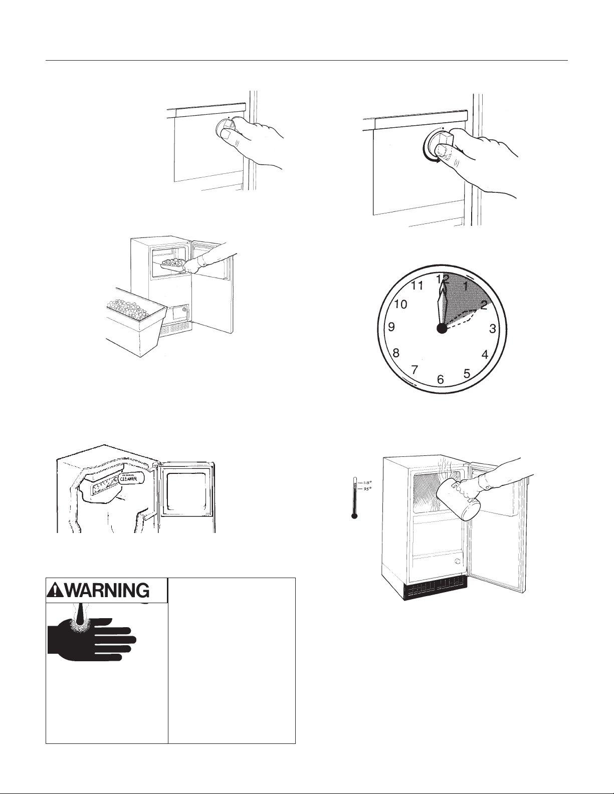
CLEANING
How to clean the ice making system.
1. Open the door and
turn the ice machine
control knob to off.
2. Scoop out all of the ice, either discard it or save
it in a ice chest or cooler.
3. Pour 4 ounces of Scotsman Ice Machine
Cleaner (available from a local Scotsman
Distributor or Dealer, ask for part number
19-0343-06 - an 8 ounce bottle) into the ice
machine reservoir.
4. Turn the ice machine control to ON.
5. Allow the machine to operate for about 2 hours.
6. Pour hot (95
0
F.-115
0
F.) water into the bin to
melt the ice that has formed. That ice will likely be
white and frosty looking.
7. Clean the bin liner of mineral scale by mixing
some ice machine cleaner and hot water, and
using that solution to scrub the scale off of the
liner.
8. Rinse the liner with hot water.
9. Sanitize the bin interior.
10. Replace the ice removed in step 2.
The ice scoop should be washed regularly, wash it
just like any other food container.
DCE33
September 2011
Page 17
Scotsman Ice Machine
Cleaner contains acids.
These compounds may
cause burns.
If swallowed, DO NOT
induce vomiting. Give
large amounts of water or
milk. Call Physician
immediately. In case of
skin contact, flush with
water. Keep out of the
reach of children.
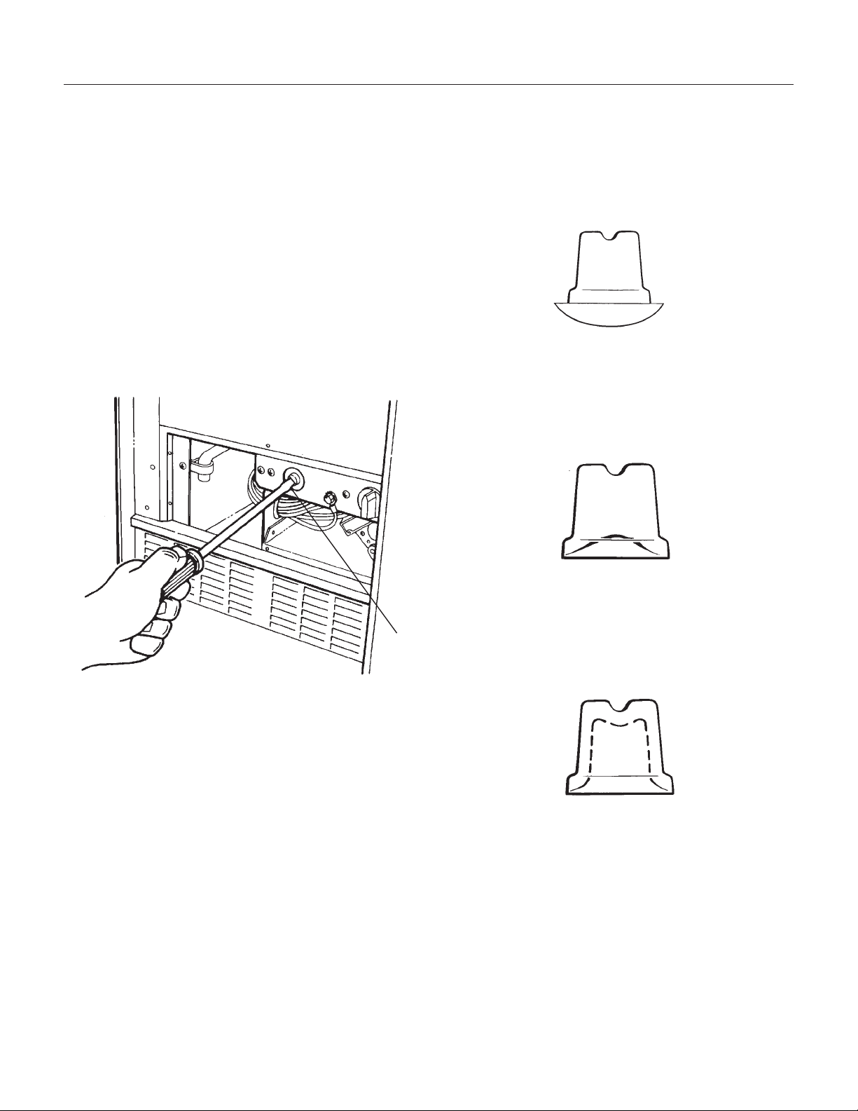
ADJUSTMENTS
There are three items that may be adjusted: Cube
Size, Harvest Time, and Bin Level. Note: Cube
Size and Harvest Time adjustments should only be
done by a qualified service person.
Cube size control.
The cube size control should only be adjusted to
bring the cubes to the correct shape, the overall
size cannot be adjusted. Try to adjust the cube
size control when the ice machine is in the harvest
cycle, or in the first 10 minutes of the freeze cycle.
1. Open the door and remove the control box
cover.
2. Locate the cube size adjustment screw, and to
make fuller cubes, turn the screw clockwise about
1/4 turn. This will make the freezing cycle longer.
3. To shorten the freezing cycle and make cubes
that are not as full, turn the adjustment screw 1/4
turn counterclockwise.
4. After the next freezing cycle, the cubes should
have responded to the adjustment, if another
adjustment is required, do it early in the freeze
cycle.
DCE33
September 2011
Page 18
CUBE SIZE ADJUSTMENT
TOO
BIG
CORRECT
SIZE
TOO
SMALL
SIDE VIEW OF CUBES
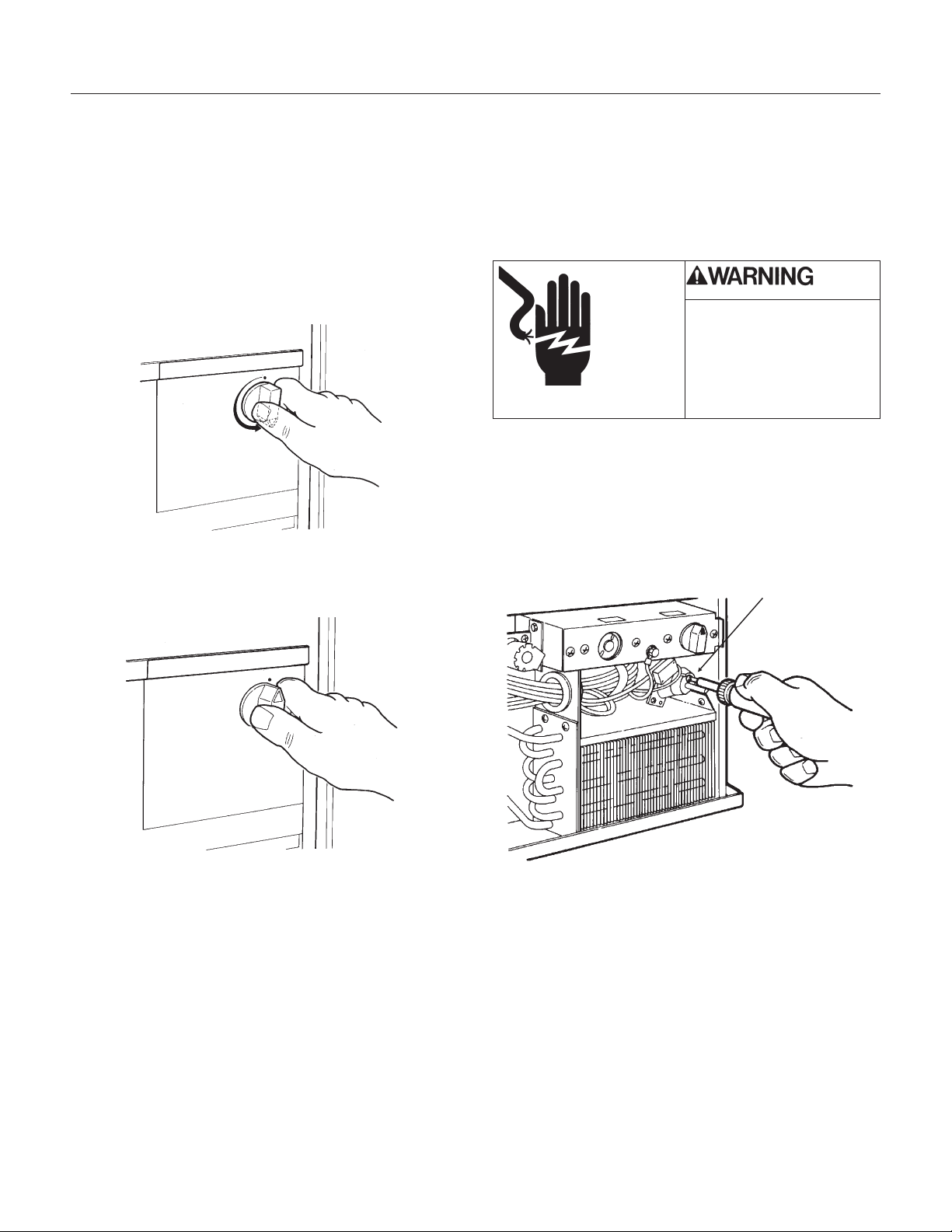
Bin’s ice level.
When the ice machine shuts off the ice level in the
bin should be even with the metal tube inside the
bin. If the ice in the bin is too high or low, turn the
ice machine control knob to adjust the bin
thermostat.
1. To lower the ice level, turn the knob
counterclockwise. Usually a 1/8 turn will be
enough.
2. To increase the ice level, turn the knob
clockwise. Usually a 1/8 turn will be enough.
Timer - up to DCE33A-1BD, DCE33PA-1BD,
DCE33A-1SSD or DCE33PA-1SSD
The amount of harvest time may be adjusted. It is
preset from the factory at about 3 minutes, which
should be adequate to release all cubes and fill the
reservoir. If the timer needs to be adjusted:
1. Unplug or disconnect the electrical power.
2. Remove the kickplate.
3. Remove the control box cover.
4. Locate the timer, and loosen the set screw that
holds the two halves of the timer cam together.
5. Rotate one half of the cam to open or close the
lower portion of the cam. More of an opening
equals more harvest time and less of an opening
means less harvest time.
6. Tighten the set-screw.
7. Replace the control box cover and kickplate.
8. Reconnect the electrical power.
DCE33
April 2013
Page 19
Timer Set Screw
ADJUSTMENT OF THE TIMER
Electrical Shock Hazard
Disconnect Electrical
Power Before Beginning
Removal of Parts
ADJUSTMENTS
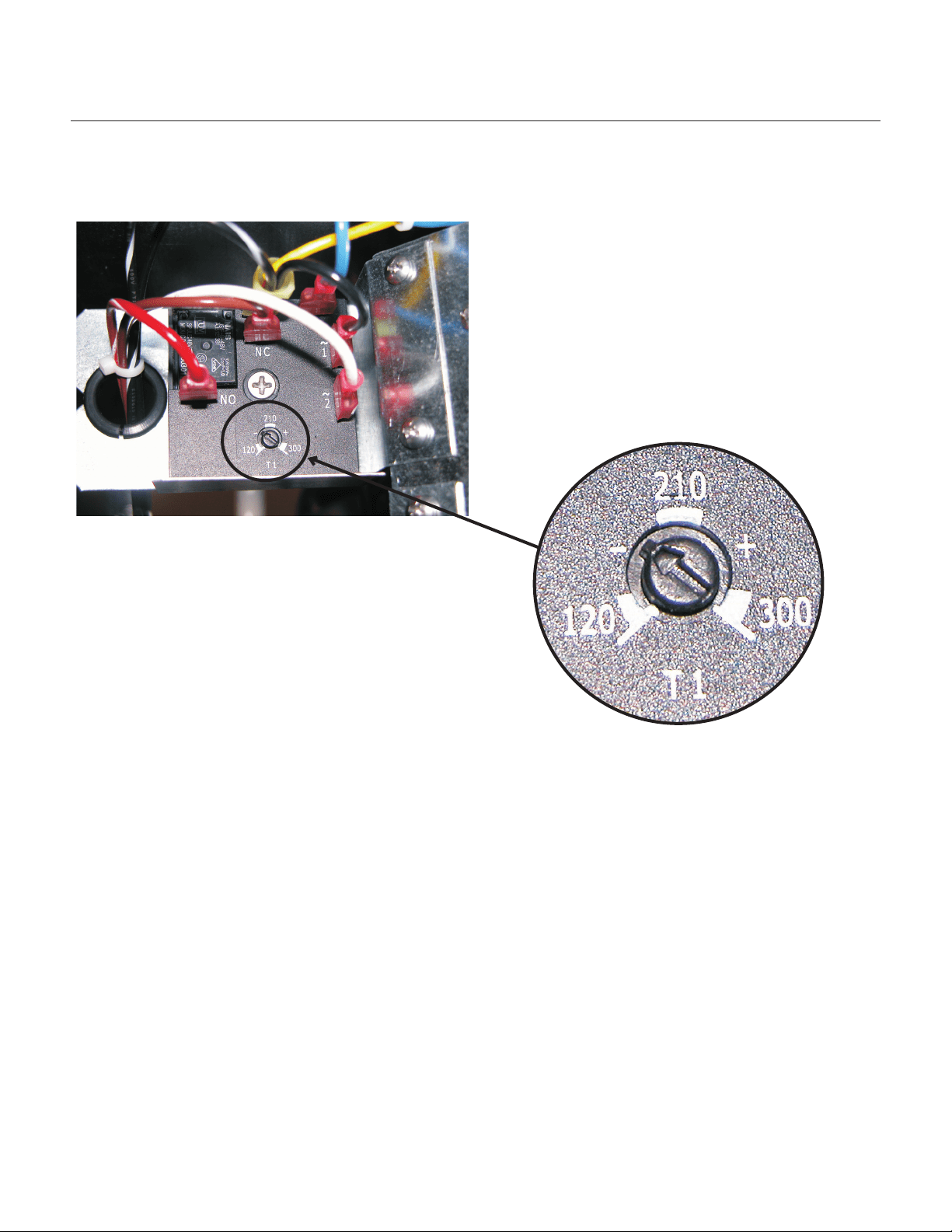
HARVEST TIME ADJUSTMENT, models DCE33A-1BD, DCE33PA-1BD,
DCE33A-1SSD or DCE33PA-1SSD
The harvest time can be adjusted so that all the ice
is released during the harvest period, with a few
seconds extra for a safety margin. The adjustment
range is between 2 to 5 minutes.
There is an adjustment screw on the surface of the
electronic timer. Rotate the screw CCW to reduce
harvest time, and CW to increase it. It should be
set to match the machine's performance. If the
machine takes 2 and a half minutes to release the
ice, the harvest time should be set to about 3
minutes.
DCE33
September 2011
Page 20
SERVICE DIAGNOSIS
DCE33
September 2011
Page 21
PROBLEM POSSIBLE CAUSE PROBABLE CORRECTION
The machine does not operate The machine is unplugged Plug the machine in.
Breaker tripped or fuse is blown. Reset breaker/replace fuse - if it
happens again, call for service to
check for a short circuit in the
machine.
Ice machine control turned to
OFF.
Turn ice machine control to ON.
Bin thermostat open keeping
machine off.
Ice on sensor tube - its then
normal for the machine to be off.
Ice machine in a room below 50
degrees - room needs to be
warmer for machine to operate.
Bin thermostat stuck open, needs
to be replaced.
Timer contacts open. Replace timer.
Cubes are too big Cube size control set too cold. Adjust cube size control for a
smaller cube.
Cubes are too small Cube size control set too warm. Adjust cube size control for a
larger cube.
Not enough water. Check water supply - filter may be
restricted.
Check inlet water valve - inlet
screen may be restricted.
Cube size control stuck closed -
timer runs all the time.
Replace cube size control
Cubes are partially formed - have
ragged sides
Spray jets partially clogged. Clean ice making system with ice
machine cleaner.
Machine makes ice, but bin does
not fill up with ice
The bin should fill up and the
machine shut off in 24-36 hours. If
not, the condenser may be dirty.
Clean the condenser.
The bin drain may be partially
restricted
Clean out the drain, check the
installation.
The air flow to the ice machine
may be obstructed.
Check the installation - the
machine must be free of
obstructions at the kick plate.
Cubes are partially formed - are
white at the bottom
Not enough water in the reservoir. Check water supply - filter may be
restricted
Check inlet water valve - inlet
screen may be restricted.
Check for a water leak at the
reservoir.
Water leaking into bin from torn or
mis-positioned curtain. Check
curtain position and condition.
Reposition or replace as needed.
SERVICE DIAGNOSIS
DCE33
September 2011
Page 22
PROBLEM POSSIBLE CAUSE PROBABLE CORRECTION
No ice falling in bin, but machine
operates
Ice may be stuck in the evaporator
and the unit is “frozen up”.
Check water supply - filter may be
restricted
Check inlet water valve - screen
may be restricted, or valve does
not operate.
Hot gas valve may not operate -
check and repair/replace.
Harvest time set too short - timer
needs adjustment.
Too much heat load. Inlet water valve leaks thru, needs
to be replaced.
No water spray Water pump does not work,
replace it.
Water leak from reservoir, locate
and repair.
Cube size control will not close See “Too much heat load” or “not
enough refrigerant”
Control defective - must be
replaced.
No airflow Fan motor not turning, needs to
be replaced.
Fan blade broken, needs to be
replaced.
Condenser completely blocked
up, needs cleaning.
Not enough refrigerant Add low side access valve, locate
leak, recover refrigerant, repair,
replace dryer, evacuate and weigh
in the nameplate charge.
Restricted system Add low side access valve,
recover refrigerant, replace dryer,
evacuate and weigh in the
nameplate charge.
Hot gas valve leaks thru Add low side access valve,
recover refrigerant, replace hot
gas valve and dryer, evacuate and
weigh in the nameplate charge.
Compressor will not operate or
pumps poorly.
Start relay or capacitor needs to
be replaced.
Add low side access valve,
recover refrigerant, replace
compressor and dryer, evacuate
and weigh in the nameplate
charge.
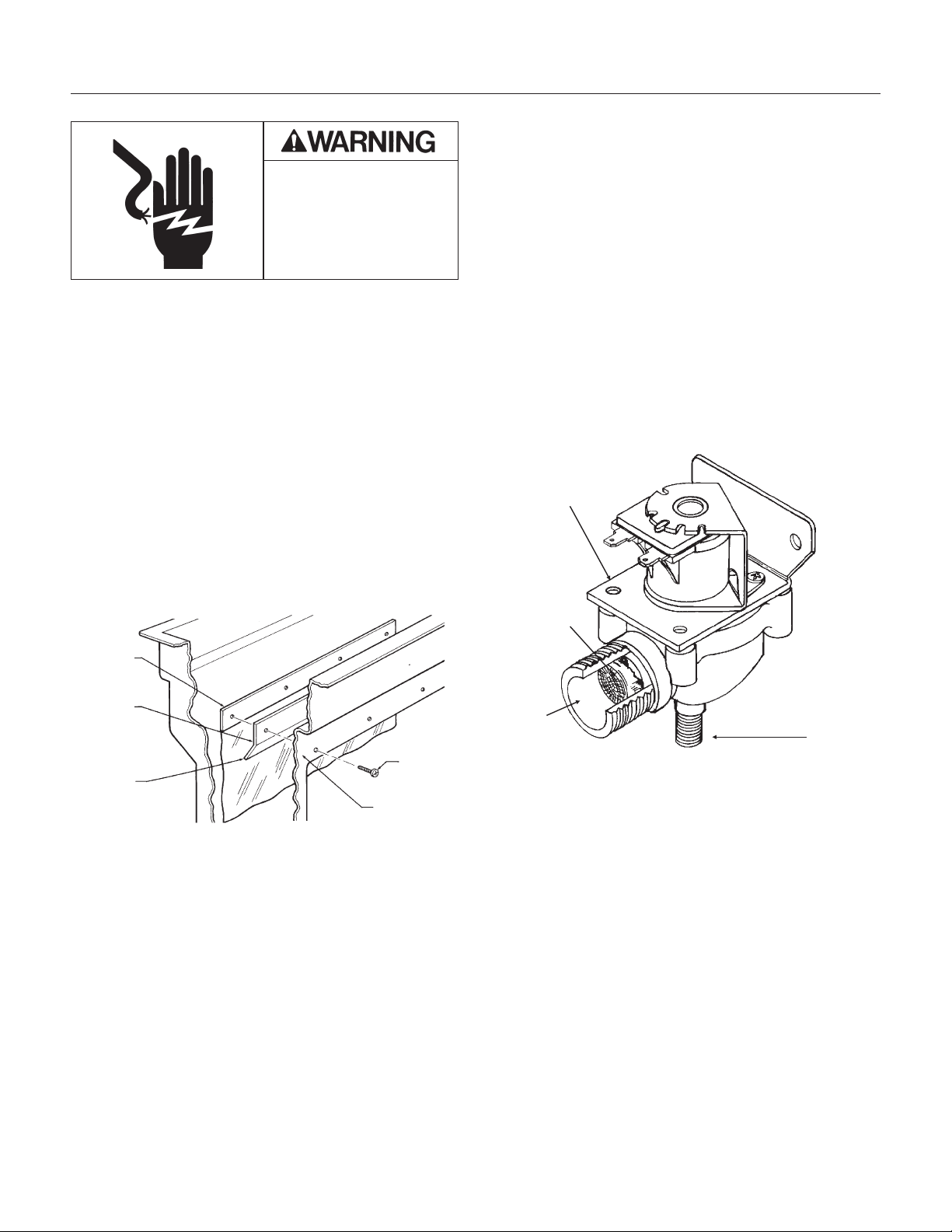
REPAIR
Curtain
The curtain keeps the water that sprayed by the
pump from falling in the bin.
The “sheet” type curtain is replaced by:
1. Removing 4 screws holding the curtain and the
curtain stiffener to reservoir.
2. Pulling the curtain and curtain stiffener out of the
machine.
3. Replace with a new curtain and install as shown.
Inlet Water Valve
The inlet water valve may need to be cleaned or
replaced. If there is not enough water coming into
the machine, the valve may need to be cleaned. If
the valve does not work at all, or does not shut off
tightly, it should be replaced.
1. Unplug or disconnect electrical power.
2. Shut off water supply
3. Remove kickplate
4. Remove the control box cover.
5. Unscrew flare nut from inlet water valve inlet . If
the valve is being replaced, proceed to step 10.
6. Unscrew brass fitting from body of inlet water
valve.
Check the screen of the valve, it may be clogged
and is restricting the flow of water into the
machine. If that is the problem, clean the screen
and reverse the steps so far to reassemble.
7. Loosen the screws in the back of the control
box, and remove the inlet water valve.
8. Remove the discharge hose from the outlet of
the water valve.
9. Unplug the wire harness from the top of the
valve.
10. Replace with a new valve, and reverse the
above steps to reassemble.
DCE33
September 2011
Page 23
Electrical Shock Hazard
Disconnect Electrical
Power Before Beginning
Removal of Parts
Inlet Water Valve
Inlet
Screen
Outlet
SERVICE OF THE INLET
WATER VALVE
Curtain
Screw
Curtain
Sheet
Type:
Curtain
Stiffener
Bottom Edge
Angle to Rear
Front Edge of
Reservoir
Curtain and Curtain Stiffener MUST Be Installed
As Shown
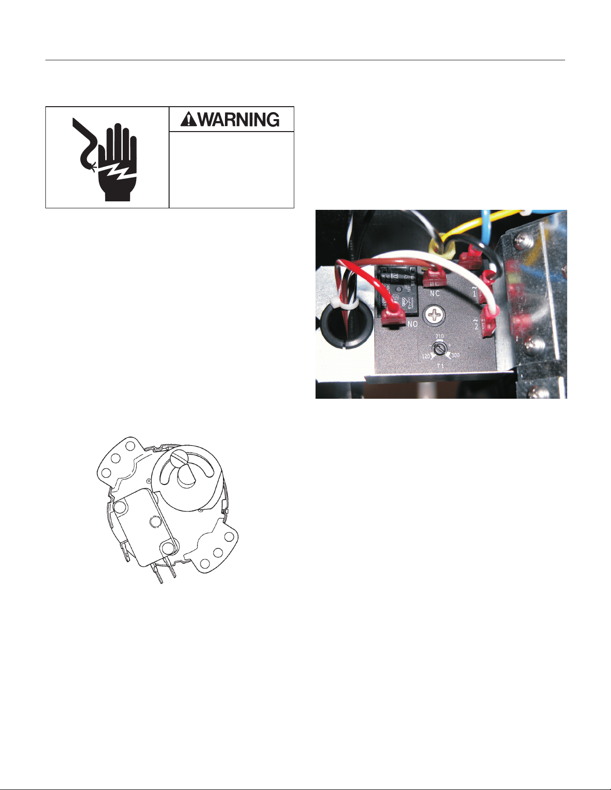
REPAIR
Timer - All except DCE33A-1BD,
DCE33PA-1BD, DCE33A-1SSD or
DCE33PA-1SSD
The timer may need to be replaced if it does not
turn, or if it turns and then stops (except at the end
of the harvest cycle - the timer will ALWAYS stop at
the end of the harvest cycle), or if the microswitch
mounted to it does not switch the machine from the
freeze to the harvest and back again.
Caution: The timer is controlled by the cube size
control, and will not turn if the cube size control
does not work.
1. Unplug or disconnect the electrical power to the
ice machine.
2. Remove the kickplate.
3. Remove the control box cover.
4. Remove the screws holding the timer to the
control box.
5. Disconnect the wires at the timer microswitch.
6. Disconnect the wires from the timer motor at the
terminal board.
7. Remove the timer from the ice machine.
8. Reverse the above steps to replace.
Harvest Timer - DCE33A-1BD, DCE33PA-1BD,
DCE33A-1SSD or DCE33PA-1SSD
1. Disconnect electrical power.
2. Remove service panel.
3. Remove screw in center of timer, pull out and
disconnect wires.
4. Reverse steps to reassemble.
DCE33
April 2013
Page 24
Electrical Shock Hazard
Disconnect Electrical
Power Before Beginning
Removal of Parts
Timer
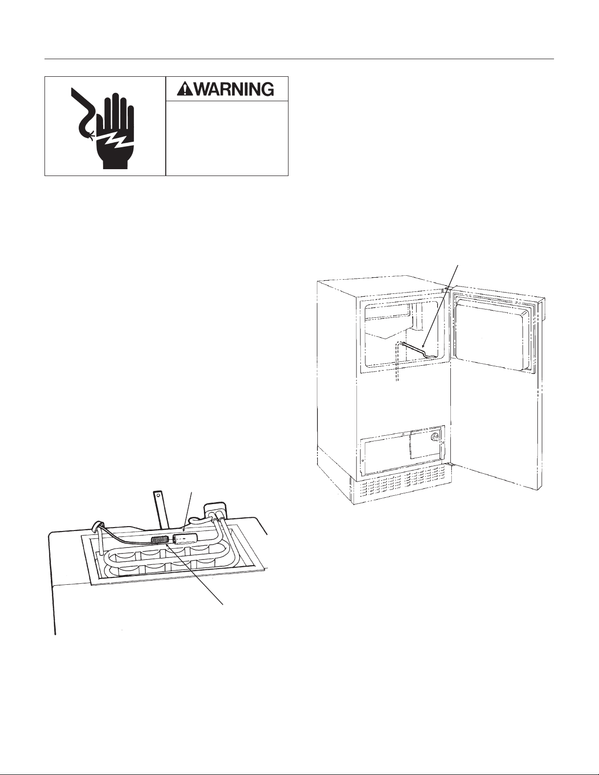
REPAIR
Cube Size Control
The cube size control controls the timer during the
freeze cycle. If the timer will not start, the cube size
control may be the problem. Removal of the cube
size control requires removal of the ice storage bin.
1. Unplug or disconnect the electrical power to the
ice machine.
2. Remove the kickplate.
3. Go thru the steps to remove the ice storage bin.
4. Remove screws holding cube size control body
to control box.
5. Remove wires connected to the cube size
control.
6. Carefully pull cube size control and attached
capillary tube from the control box, and follow the
capillary tube to the top of the evaporator.
7. The end of the cube size control is inserted into
a socket attached to the evaporator.
8. Remove the cube size control from the socket
and from the ice machine.
9. Reverse the above steps to replace.
10. Adjust the cube size control per the adjustment
sequence on page 16.
Bin Thermostat
The bin thermostat is the automatic on-off control
for the ice machine.
1. Unplug or disconnect the electrical power to the
ice machine.
2. Pull the machine out from its installed location.
3. Remove the back panel.
4. Remove the kickplate.
5. Remove the control knob
6.. Remove the control box cover.
7. Remove the screws holding the bin thermostat
to the control box.
8. Remove the wires attached to the bin
thermostat.
9. Pull the bin thermostat and capillary tube from
the control box, trace the capillary tube to the bin
level control tube and remove the capillary tube
from the tube. Remove the bin thermostat from the
ice machine.
10. Reverse the above steps to replace.
DCE33
September 2011
Page 25
Electrical Shock Hazard
Disconnect Electrical
Power Before Beginning
Removal of Parts
Socket
Pig Tail
CUBE SIZE CONTROL
REPLACEMENT
Capillary Tube
Bin Thermostat
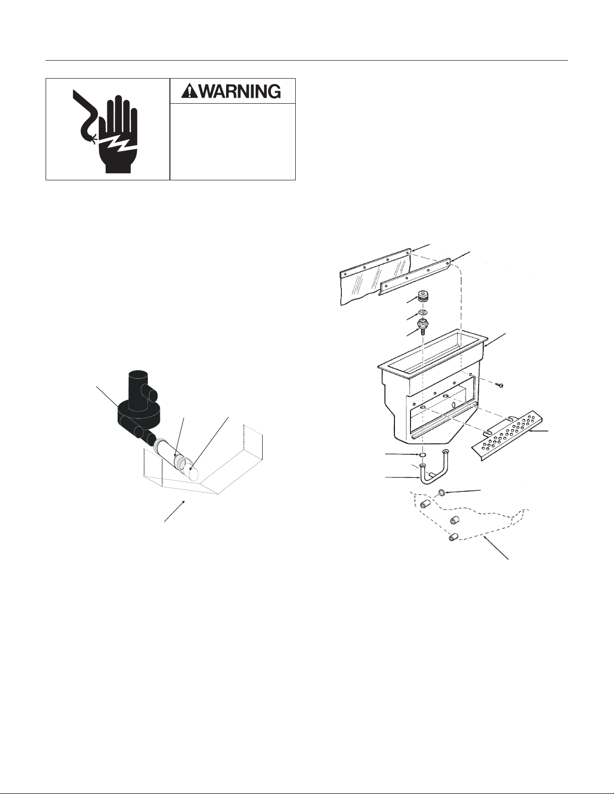
REPAIR
Spray Pump
The water pump that forces the water from the
reservoir through the spray jets.
1. Disconnect electrical power.
2. Open the bin door and locate the three hoses
connected to the water pump.
A. Loosen the hose clamps from the pump hoses.
B. Remove the pump hoses from their
connections.
3. Disconnect water and drain tubes.
4. Carefully pull machine out from its installed
location to expose the back panel.
5. Remove the back panel.
6. Disconnect wires from the top of the pump
motor.
7. Remove two screws holding pump to bin, and
remove the pump from the ice machine.
8. Reverse the above steps to re-assemble.
Spray Jets
Spray Jets are small nozzles that are under the
freezing surface, they spray a narrow pattern of
water at the freezing surface. If plugged or
restricted, poorly shaped ice cubes will form.
If the spray jets are removed the o-rings between
the water inlet tube and the spray jet bases must
be in place (see illustration).
DCE33
September 2011
Page 26
Electrical Shock Hazard
Disconnect Electrical
Power Before Beginning
Removal of Parts
Pump Hose Removal
Spray Pump
(for reference)
Hose Clamp
Suction
Hose
Reservoir
(for reference)
Curtain
Curtain Stiffener
Cap
Spinner
Jet Base
Reservoir
Body
Cube
Chute
O-Ring
Pump
Discharge
O-Ring
Back view of
Reservoir

DCE33 SERVICE PARTS
The section contains the parts list for the DCE33. The DCE33 has been manufactured in either a White,
Black or Stainless Steel finish.
A "D" series model was introduced in 2011 (as in DCE33A-1BD
), it has a different timer and wiring
diagram.
Please check the part description before ordering any part.
Table of Contents
Cabinet ····································································································································· Page 2
Pump, Evaporator, Storage Bin ································································································ Page 3
Drain Pump Components ········································································································· Page4
Condensing Unit ······················································································································· Page 5
Reservoir ·································································································································· Page 6
CONTROL BOX - all models except DCE33A-1BD, DCE33PA-1BD, DCE33A-1SSD or
DCE33PA-1SSD ······················································································································· Page 7
CONTROL BOX - for DCE33A-1BD, DCE33PA-1BD, DCE33A-1SSD or DCE33PA-1SSD ··· Page 8
Compressor ······························································································································ Page 9
Drain Pump Model Wiring Diagram - Prior to August 2000 ····················································· Page 11
Gravity Drain Model Wiring Diagram - Prior to August 2000 ··················································· Page 12
Drain Pump Model Wiring Diagram after August 2000 up to D series ···································· Page 13
Gravity Drain Model Wiring Diagram after August 2000 up to D series ·································· Page 14
Wiring Diagram for DCE33A-1BD, DCE33PA-1BD, DCE33A-1SSD or DCE33PA-1SSD ······· Page 15
Schematic Diagram DCE33A-1BD, DCE33PA-1BD, DCE33A-1SSD or DCE33PA-1SSD ····· Page 16
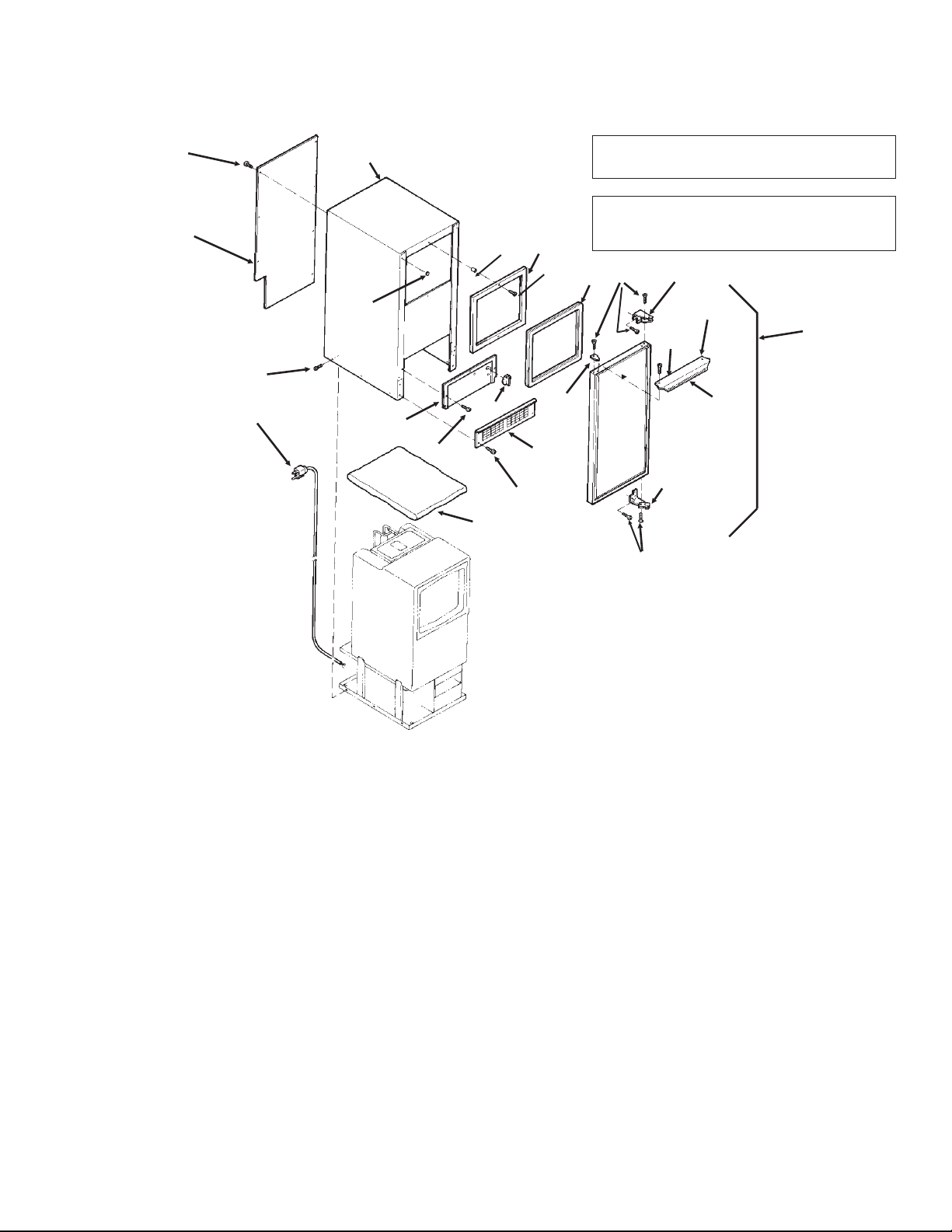
DCE33 SERVICE PARTS
April 2013
Page 2
1,
includes items
2,3,4,5,6, & 7
2
9
17
22
14
13
16
20
10
4
21
15
3,
includes 5
8
11
7
19
7
6
18
5
8a
8b
23
Item Part
Number Number Description
1. A32117-003 White Door Assembly
A32117-010 Black door assembly
A28866-012 Stainless door assembly
2. 13-0826-04 Gasket
3. A29043-001 Alum. Door Handle (white)
A29043-003 Alum. Door Handle, (black)
4. 03-1607-01 Head Screw (2)
5. 15-0730-01 Nameplate strip (white)
15-0730-02 Nameplate strip (black)
6. 15-0648-01 Alum. Hinge Fill Plate, Rt.
15-0648-02 Alum. Hinge Fill Plate, Lt.
7. 03-1418-24 Screw (10)
8. 13-0828-01 Gasket (white)
13-0828-02 Gasket (grey)
8a 03-1419-08 Screw - not for ss
03-1404-26 Screw for SS cabinets
8b 02-2701-01 Spacer
9. 03-1419-26 Screw, black
03-1419-29 Screw, white
10. 15-0799-01 Hinge
Item Part
Number Number Description
11. 15-0799-02 Hinge
13. 02-3141-01 Knob, Bin Thermo
14. A34877-002 Cont Box cover - white
A34877-003 Cont Box cover - black
A40162-001 Cont Box cover - SS
14a 17-3465-01 Bin level control label
15. 03-1404-07 Screw (6)
16. 02-2243-02 Kickplate - black
17. A29102-001 Rear Panel
18. 03-1404-08 Screw (9)
19. 02-2481-01 Plug (6) (white)
02-2481-02 Plug, black
02-1874-11 Plug, nickel
20. A38803-021 Cabinet (white)
A38803-022 Cabinet (black)
for flat head screws, use began w/sn 05111320015862
A40159-001 Cabinet (stainless steel)
21. A26787-001 Insulation (in Bag)
22. 12-2571-01 Power cord & wire harness
12-1638-21 For D series
23 03-1431-00 Screw, pan head
03-1419-29 Flat head screw, white
Note: Items 20 and 23. Item 20 only available
for use with flat head screws. Prior cabinets
used pan head screws.
Cabinet
Note for SSD models only: Magnetic strips
inside cabinet - 02-4738-01 and 02-4738-02.
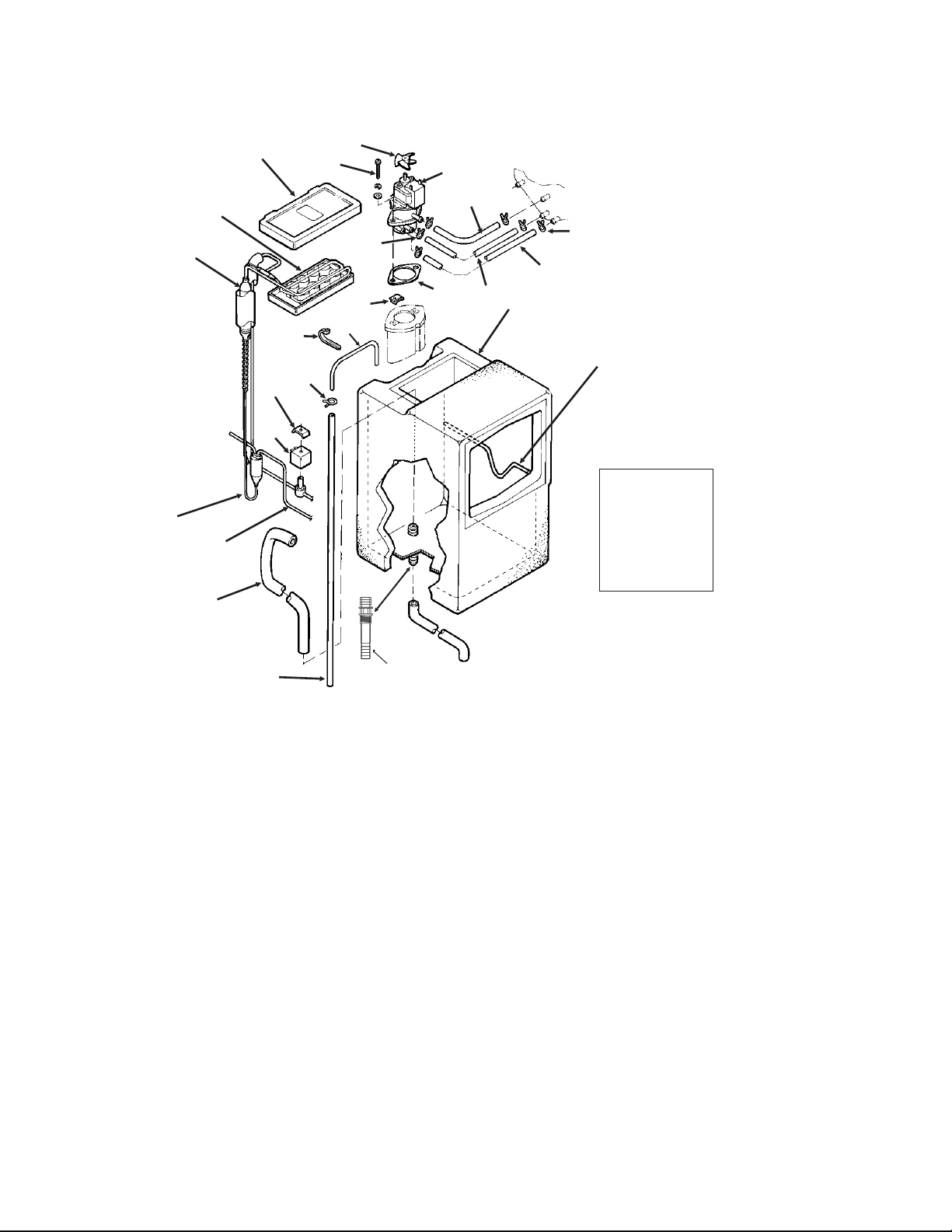
DCE33 SERVICE PARTS
September 2011
Page 3
14
SCOOP
(not shown)
PN: 02-3070-01
(plastic)
08-0664-01
(metal)
4
5
1
8
15
16
12
7
9
11
6
13
1
17, includes 3, & res. drain
20
19
18
3
2
Pump, Evaporator, Storage Bin
21
17a,17b,
17c
2b
2c
2a
Item Part
Number Number Description
1. 02-2274-01 Platen Cover
2. 13-0674-01 Tube, 37"
2a A27027-001 Copper inlet tube
2b no number Tube holder
2c 02-1727-01 Hose clamp
3. A34816-001 Bin Thermostat bracket
4. 02-3489-20 Evaporator, does NOT
include suction line and accumulator
5. A36699-020 Evaporator, Complete
6. 13-0899-01 Res. drain hose
7. 13-0674-16 Tube, 5/8" Req. 4.25"
8. 13-0674-15 Tube,1/2", Req 3.25"
9. 13-0674-15 Tube, 1/2", Req. 3-5/8"
10. 02-1775-02 Clamp (2)
11. 02-0534-02 Clamp (4)
12. 02-1719-00 Fan Blade
13. A30625-001 Spray Pump
14. 13-0687-00 Gasket
15. 03-1719-01 Screw
16. no longer used Speed Nut (2)
17. A36930-020 Bin Assembly, includes
reservoir drain hose & drain fittings
17a 02-3323-01 Drain fitting
(foamed in bin)
17b 13-0617-13 O-Ring
17c 03-1394-05 Pal nut
18 12-2569-03 Clip, Hot Gas Valve
19. 12-2569-02 Coil, Hot Gas Valve
replaces coils that have encapsulated wires
11-0562-22 Coil, hot gas valve
replaces coils that have terminals
20. 11-0562-21 Hot Gas Valve kit
21 02-3490-01 Drier
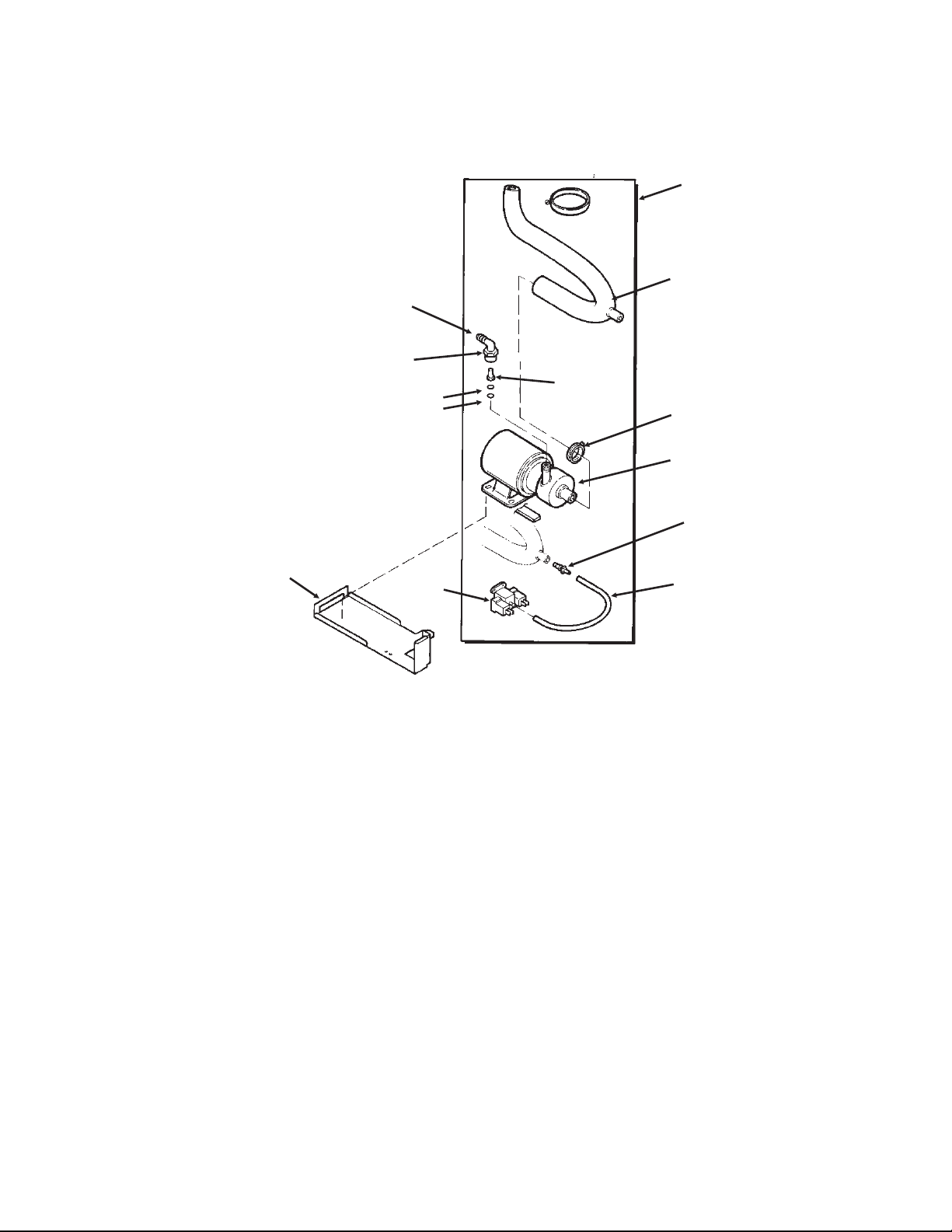
DCE33 SERVICE PARTS
April 2013
Page 4
Drain Pump Components
3
1
2
7
6
10
4
5
9
13
12
11
Item Part
Number Number Description
1. A36892-020 Drain Pump Kit, for all except DCE33A-1BD and DCE33A-1SSD
A39885-001 Drain pump kit, for DCE33A-1BD or DCE33A-1SSD
use to convert any DCE33 gravity model to pump type. Pump must be ordered separately.
2 12-2503-21 Drain pump only,
use to replace drain pumps or w/kit to convert.
Pump Kit Service Parts
3 02-3369-01 Inlet hose
4 02-3522-01 Elbow
5 02-3374-01 Check valve
6 13-0617-08 O-ring
7 11-0504-01 Pressure switch
8 obsolete Impeller & housing kit
9 A37334-001 Discharge hose
10 05-0591-01 Switch hose
11 A36746-001 Mounting bracket
12 02-3406-01 Barbed connector
13 02-2814-11 Clamp
14 12-2580-01 Harness
12-3001-01 Harness, for converted-to-pump DCE33A-1BD, DCE33PA-1D, DCE33A-1SSD
or DCE33PA-1SSD
15 03-3904-01 Check valve spring
15
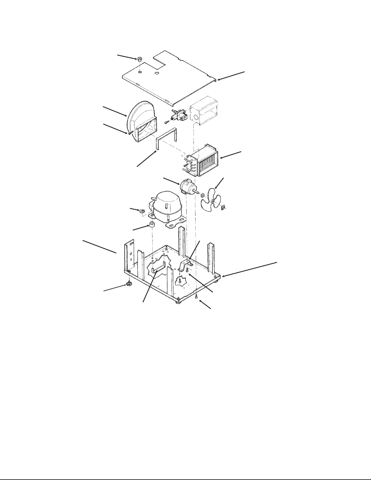
DCE33 SERVICE PARTS
April 2013
Page 5
Item Part
Number Number Description
1. 03-1404-08 Screw (4)
2. 18-3710-01 Fan Blade
3. A28798-001 Fan Motor Bracket
4. 12-2396-21 Fan Motor
18-8752-10 Blade pad
18-8752-11 Blade nut
5. 02-2871-01 Fan Shroud
6. 18-3729-01 Condenser
7. 18-4700-28 Grommet
8. 03-1608-01 Leg Leveler
9. 03-1407-08 Washer
03-3821-01 Clip
10. A29015-001 Bracket
Item Part
Number Number Description
11 12-1213-10 Bushing
12 A37732-001 Upper base plate
13 13-0609-00 Foam tape
14 A28921-001 Lower base plate
A38638-001 Lower base plate
use began w/sn 05111320015862
Support brackets part of item 12
A40164-001 Base pan for -1SSD
15 03-1531-01 Screw
7
4
9
8
5
6
2
10
3
1
1
12
13
14
15
Condensing Unit
Support Bracket
11
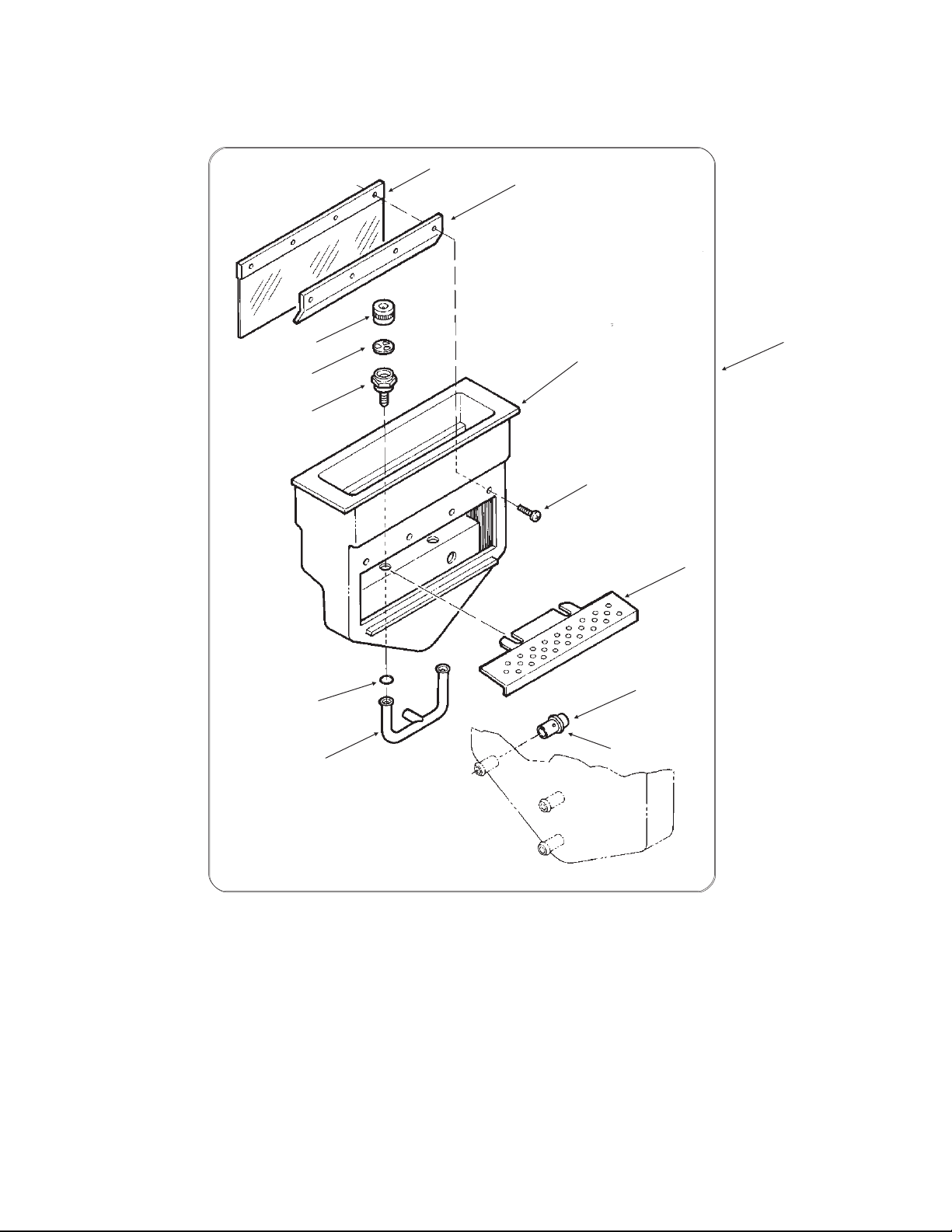
DCE33 SERVICE PARTS
September 2011
Page 6
Item Part
Number Number Description
1. 02-2479-21 Curtain
2. A24155-001 Curtain stiffener
3. 03-1404-16 Screw
4. 02-1841-00 Nozzle
5. A09543-000 Spinner
6. 02-1840-00 Jet Base
7. A22518-000 Cube Chute
Item Part
Number Number Description
8. 13-0617-08 O-ring
9. 02-2704-01 Spray Bar Assembly
10. 05-0593-01 SS nipple
11. 13-0617-01 O-ring
12. 02-1923-01 Bin Insert
13 A22532-001 Bin insert assy
3
1
2
12
4
5
6
8
9
10
11
7
13
Reservoir
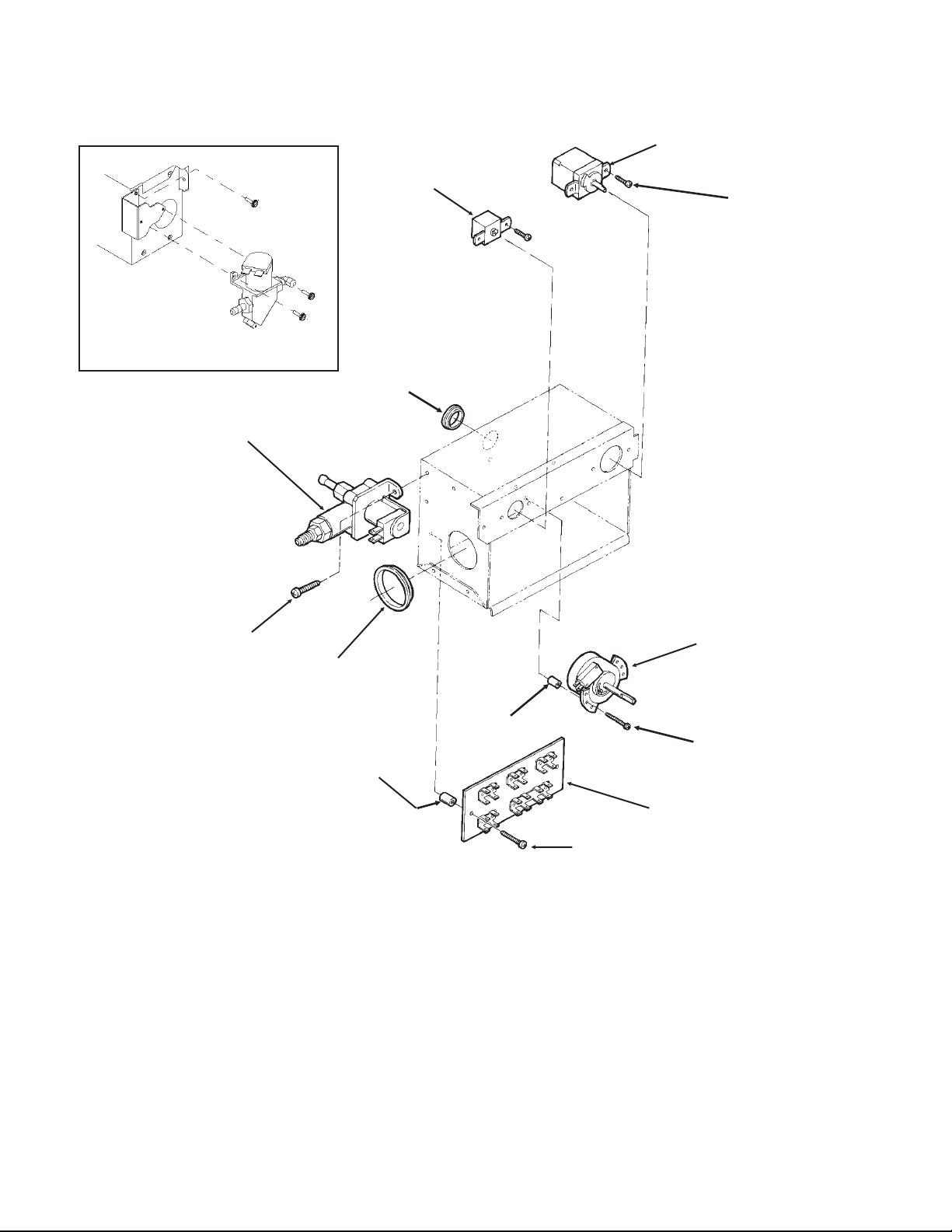
DCE33 SERVICE PARTS
April 2013
Page 7
4
6
8
7
3
1
2
8
9
11
10
12
Blue Valve Shown
Item Part
Number Number Description
1. A25981-001 Terminal Board
2. 03-1638-01 Screw
3. 12-1980-01 Timer And Switch
4. 11-0503-21 Cube Size Control
5. 11-0407-21 Bin Level Control
02-3141-01 Knob for item 5
6. 12-2907-21 Inlet Water Valve Kit
(includes new fittings)
12-2907-31 Coil only for brass valve
12-2410-31 Coil only for plastic valve
Item Part
Number Number Description
7. 12-1213-12 Bushing
8. 03-1403-17 Screw
9 12-1213-04 Snap bushing
10 03-1638-02 Screw
11 02-2242-06 Stand off
12 02-2242-05 Stand off
Not Shown
13 A39918-001 Kit to retrofit electronic
timer to prior model.
CONTROL BOX - all models except DCE33A-1BD, DCE33PA-1BD, DCE33A-1SSD or
DCE33PA-1SSD
Brass Inlet Water Valve Mounts to
Control Box As Shown
5
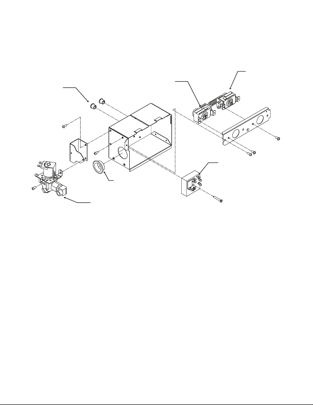
DCE33 SERVICE PARTS
April 2013
Page 8
CONTROL BOX - for DCE33A-1BD, DCE33PA-1BD, DCE33A-1SSD or DCE33PA-1SSD
Item Part
Number Number Description
1 11-0503-21 Cube size control
2 11-0407-21 Bin level control
3 12-2985-01 Timer
03-1419-16 Screw
4 12-1213-12 Snap bushing
5 12-2907-21 Inlet water valve kit, includes new fittings
12-2907-31 Coil only for inlet water valve
6 12-1213-04 Snap bushing
2
1
3
5
6
4
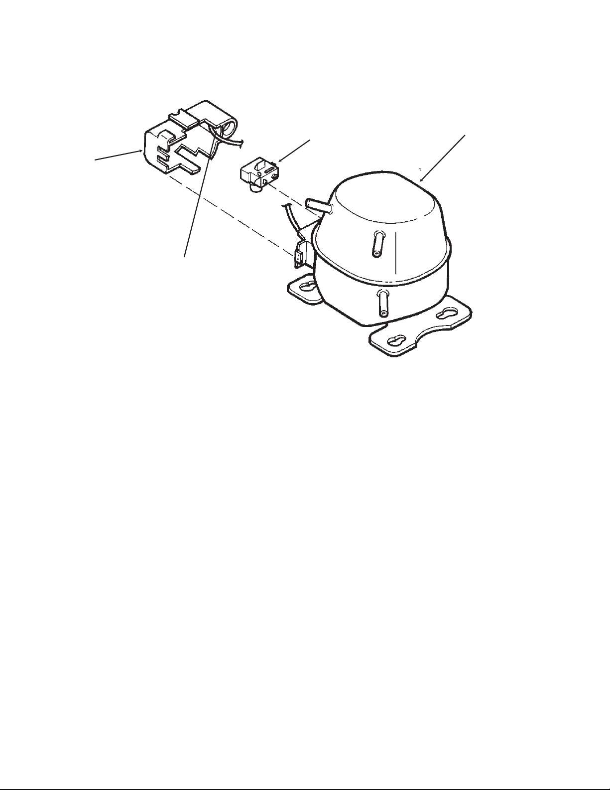
DCE33 SERVICE PARTS
September 2011
Page 9
Item Part
Number Number Description
1. 18-8776-21 Compressor Kit, Includes Relay, Overload, Instructions
2. 18-8776-51 Relay
3 18-8776-52 Overload
4. 18-8776-54 Cover
Compressor
1
2
3
4

DCE33 SERVICE PARTS
September 2011
Page 10
Kit Parts
K-SS Door Sleeve Kit
02-3846-01 Sleeve
02-3847-01 Handle
03-1403-50 Screw for handle
03-1407-06 Washer
03-1410-03 Lockwasher
03-3811-01 Screw
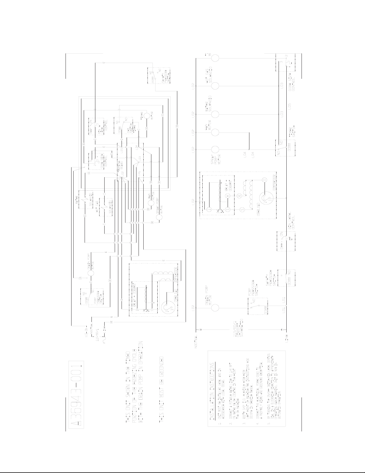
DCE33 SERVICE PARTS
September 2011
Page 11
Drain Pump Model Wiring Diagram - Prior to August 2000
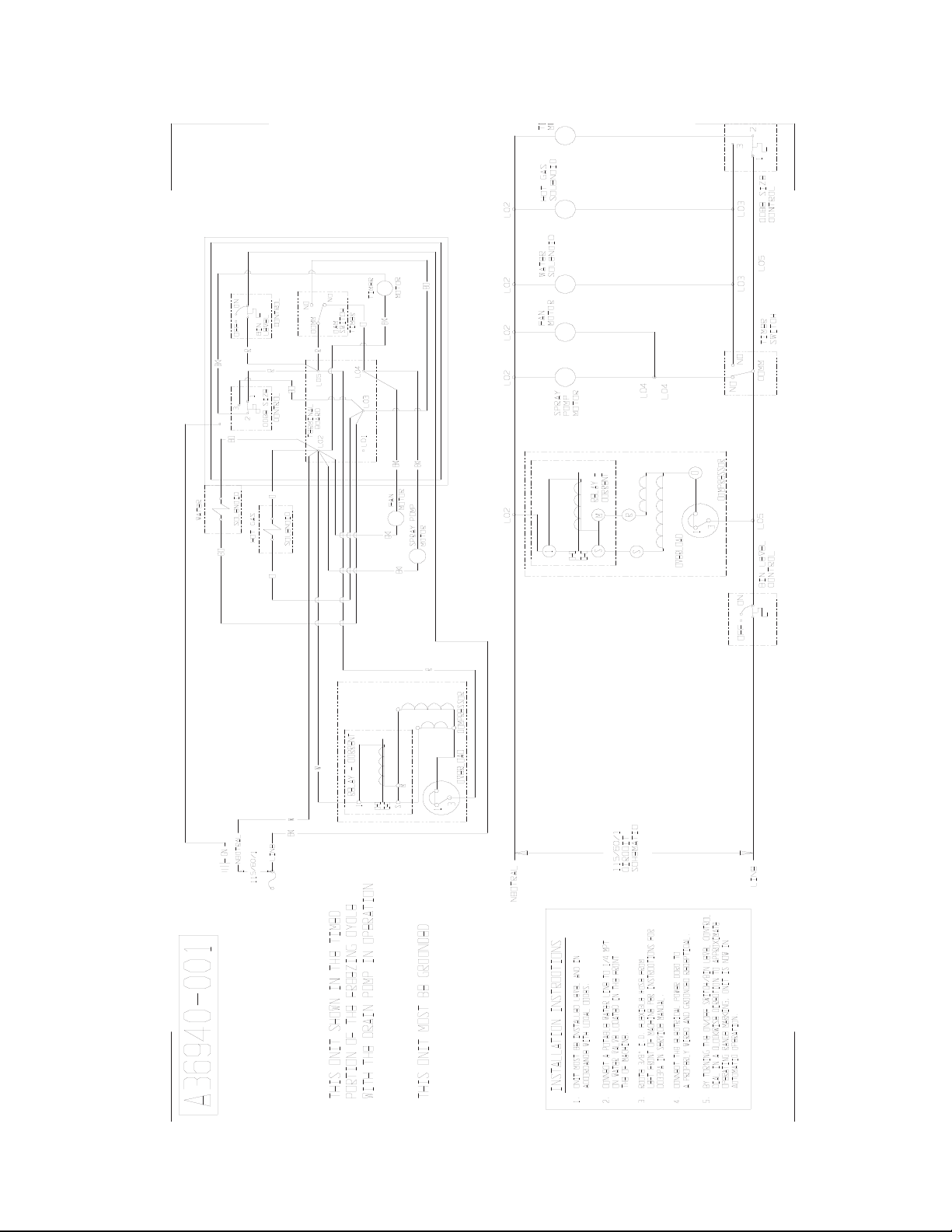
DCE33 SERVICE PARTS
September 2011
Page 12
Gravity Drain Model Wiring Diagram - Prior to August 2000
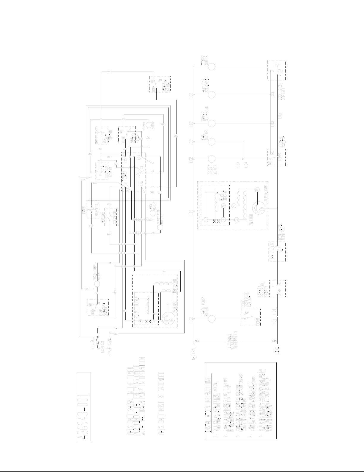
DCE33 SERVICE PARTS
September 2011
Page 13
Drain Pump Model Wiring Diagram after August 2000 up to D series
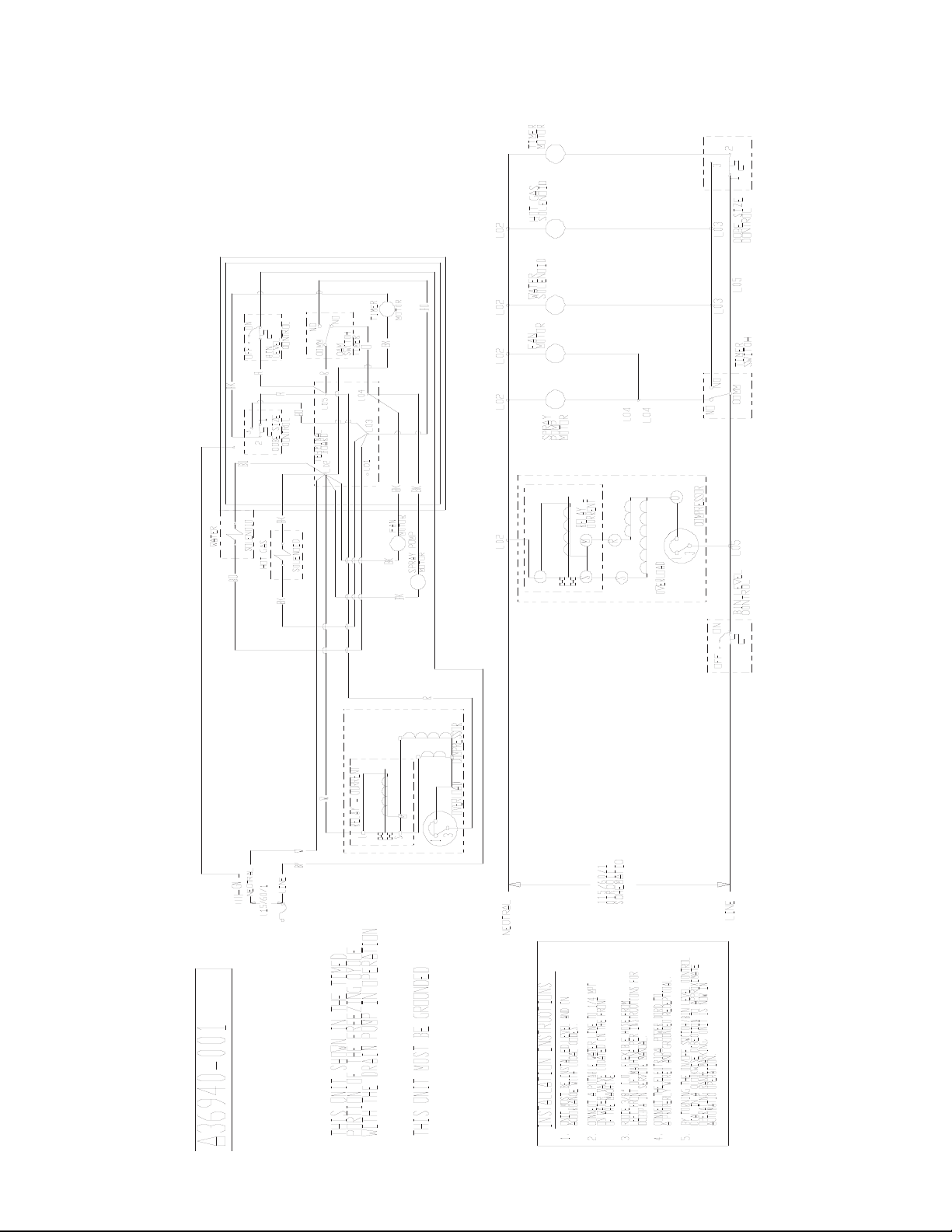
DCE33 SERVICE PARTS
September 2011
Page 14
Gravity Drain Model Wiring Diagram after August 2000 up to D series
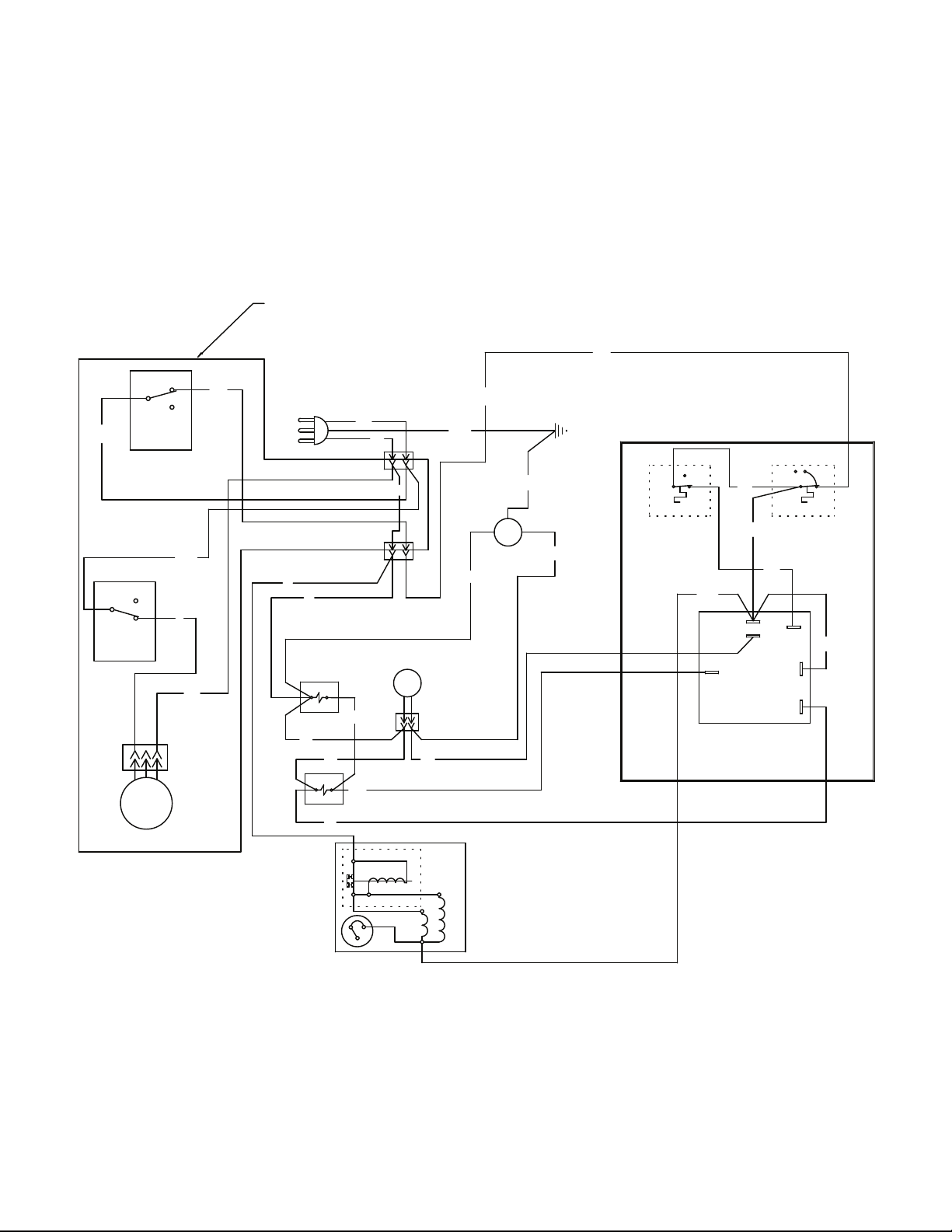
Wiring Diagram for DCE33A-1BD, DCE33PA-1BD, DCE33A-1SSD or DCE33PA-1SSD
DCE33 SERVICE PARTS
April 2013
Page 15
BU
Y
TIMER
BK
BK
W
BK/W
BK
2
1
6
C
NC
NO
COMPRESSOR
RELAY - CURRENT
OVERLOAD
1
M
S
3
1
Y
2
1
3
CONTROL
CUBE SIZE
W
DRAIN
PUMP
MOTOR
W
BK
R
BK
PUMP
PRESSURE
SWITCH
NO
COMM
NC
R
SAFETY
PRESSURE
SWITCH
NO
COMM
NC
W
PUMP
MOTOR
BU
W
W
R/W
WATER
SOLENOID
FAN
MOTOR
R
HOT GAS
SOLENOID
BN
GN/Y
EARTH GROUND
ONOFF
BIN
LEVEL
CONTROL
POWER IN
W
BK
GN/Y
W
W
IF DRAIN PUMP
IS INSTALLED
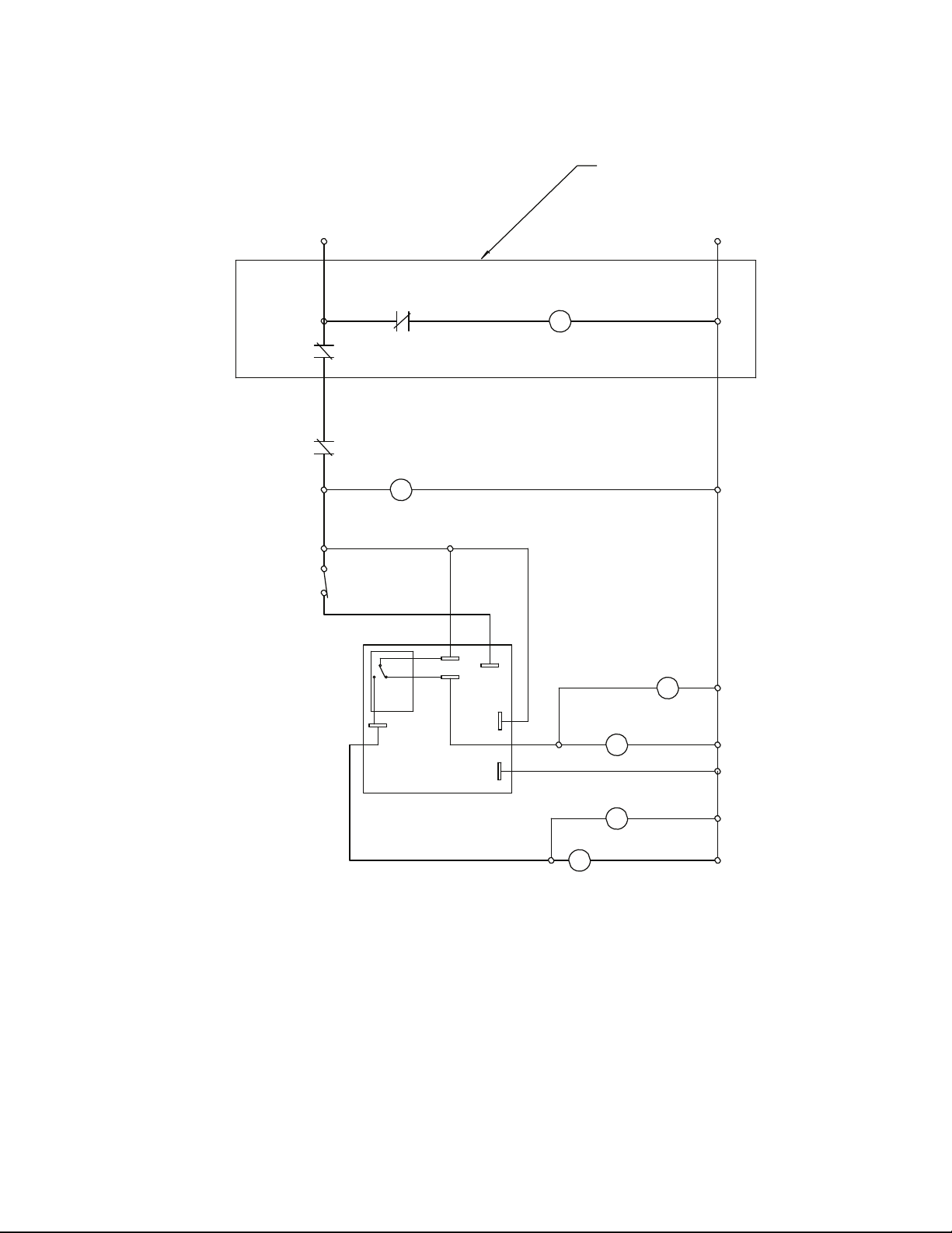
Schematic Diagram DCE33A-1BD, DCE33PA-1BD, DCE33A-1SSD or DCE33PA-1SSD
DCE33 SERVICE PARTS
April 2013
Page 16
HARVEST TIME
ADJUSTABLE
FROM 120 TO 300 SEC.
FACTORY SET TO 170
TIMER
2
1
6
C
NC
NO
CUBE SIZE
CONTROL
(INITIATE
TIMER
SWITCH)
COMPRESSOR
SWITCHES ON THIS UNIT
SHOWN IN TIMED PORTION
OF THE FREEZE CYCLE
WITH DRAIN PUMP IN OPERATION
BIN LEVEL
CONTROL
SAFETY
PRESSURE
SWITCH
DRAIN PUMP
PRESSURE
SWITCH
DRAIN
PUMP
HOT GAS
SOLENOID
FAN
MOTOR
L1
N
WATER
PUMP
WATER
SOLENOID
IF DRAIN PUMP
IS INSTALLED

SCOTSMAN ICE SYSTEMS
775 Corporate Woods Parkway
Vernon Hills, IL 60061
800-726-8762
www.scotsman-ice.com
17-2419-01 Rev A.