Loading ...
Loading ...
Loading ...
31
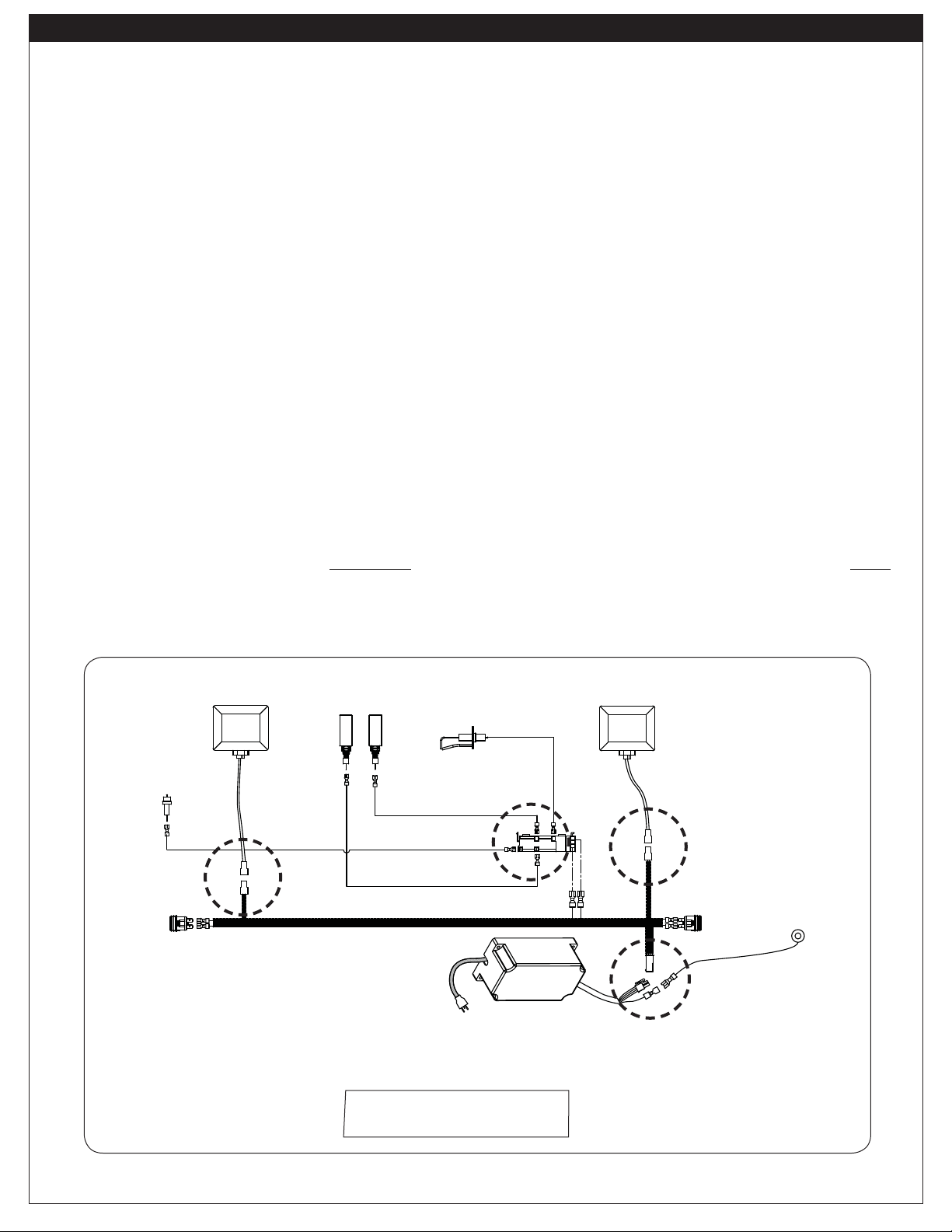
Fig. 31-1 - Wire diagram
A
B
C
D
24" model shown
(Connections may vary)
Power supply box
Wire harness
extension
Right light
Left light
Main burner
Ignitors
Backburner
Ignitor
Ignitor
module
Ignitor
switch
Light
switch
Ground wire
connection
Sideburner
Ignitor
To open the control panel:
1. Turn the control knobs to the OFF position.
2. Pull the control knobs from their stems and set them aside.
3. Using a Phillips screwdriver, unscrew the control panel fastener screws (located on the sides of the
control panel). Retain the screws for later re-installation.
4. Carefully open the control panel by lifting and pulling the control panel from the frame.
Important: When opening, take caution to not damage any wiring. The drip tray can be opened slightly
to support the control panel.
To completely remove the control panel:
1. Follow steps 1-4 above.
2. Disconnect the main wire harness connections (A), the left light connection (B), the right light
connection (C), and the ignitor wires (D). It is recommended to temporarily label the wires for reference
when reconnecting. See Fig.
31-1. When disconnecting, be sure to pull from the connectors, and
not the wires.
Note: Secure any disconnected wires (coming from the inside of the grill) to prevent them from falling
into the unit.
3. Carefully remove the control panel.
Note: Whenever reconnecting any wires, apply a small amount of dielectric grease to the male
connector, then make the connection.
Important: During reinstallation; prior to opening the gas shutoff valve, be sure the control knob(s)
are in the OFF position.
CONTROL PANEL REMOVAL
Loading ...
Loading ...
Loading ...