Loading ...
Loading ...
Loading ...
29
CHECKING/CONVERTING THE BURNER ORIFICES (Cont.)
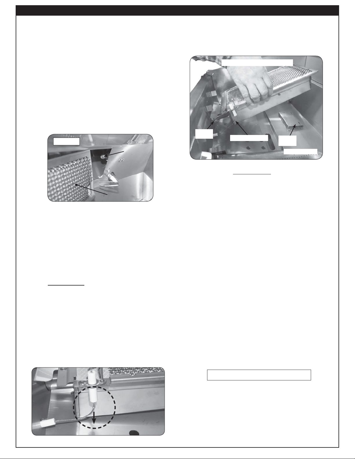
3. Carefully lift the infrared burner from the burner
support and out from the hole in the forward
fi re wall (see Fig. 29-3).
4. Using a
1
/
2
" deep socket, remove the orifi ce
from the valve. Access this through the hole
in the forward fi rebox plate (see PARTS LIST
and Fig. 29-3).
Alternatively, the orifice can be accessed
through the inside of the control panel if the
proper tool is not available. This allows a
1
/
2
"
open-end wrench to be used instead of a
1
/
2
"
deep socket nut driver. To open the control
panel, see the CONTROL PANEL REMOVAL
section.
5. Check the number stamped on the face of the
orifi ce (see Table 1).
6. If the barbecue does not have the proper
orifices installed for the gas supply you
intend to use, replace them with the correct
orifi ces. Some orifi ces were supplied with the
barbecue. They may also be obtained from the
conversion kit or supplied by your local dealer.
Note: A regulator hose will need to be
connected for conversion to propane
gas.
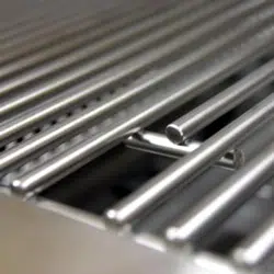
c. Carefully pull the left end of the backburner
forward until the burner can be moved to the
left pulling it free from the orifi ce located on
the right side (see Fig. 29-1).
d. Using a
3
/
8
" socket, remove the orifi ce from
the orifi ce holder and check the number
stamped on the face.
2. If an orifi ce change is necessary, replace the
orifi ce with the correctly sized one.
3. Replace the backburner assembly and the
electrode by reversing the procedure in steps
a. through c.
INFRARED BURNER ORIFICE SIZE
CHECKING/CONVERSION (IF EQUIPPED)
Before beginning, make sure you have the proper
tools for the task.
This task requires:
• a #2 Phillips-head screwdriver
• a
1
/
2
" deep socket nut driver
Note: It may be necessary to remove the
rotisserie rod before beginning this
procedure.
1. Remove cooking grids & vaporizer panels from the
barbecue.
2. Disconnect the ignitor wire from the bottom of
the electrode assembly on the infrared burner
(see Fig. 29-2).
The backburner orifi ce can be seen on the
right side after removing the backburner.
Backburner
Orifi ce
Fig. 29-1
Removing / inserting infrared burner.
Fig. 29-3
Burner
support
Hole with
orifi ce
Wire disconnected
Fig. 29-2
Spark generator
Procedure continued on next page
Loading ...
Loading ...
Loading ...