
Owner's Manual
JCRAFTSMAWJ
GARDEN TRACTOR
23.0 HP, 48" Mower
Electric Start
6 Speed Transaxle
Model No.
917.275012
I
This product has a low emission engine which operates
differently from previously built engines. Before you start the
engine, read and understand this Owner's Manual.
CAUTION:
Read and follow all Safety
Rules and Instructions before
operating this equipment.
For answers to your questions
about this product, Call:
1-800-659-5917
Sears Craftsman Help Line
5 am - 5 pm, Mon- Sat
SEARS, ROEBUCK AND CO., HOFFMAN ESTATES, IL 60179 U.S.A.
visit our Craftsman website:www.sears.corn/craftsman
Warranty ............................................... 2
Safety Rules ......................................... 3
Product Specifications .......................... 6
Assembly/Pre-Ope ration ...................... 8
Operation ............................................ 10
Maintenance Schedule ...................... 16
Maintenance ....................................... 16
Service and Adjustments .................... 21
Storage ............................................... 29
Troubleshooting ................................. 30
Repair Parts ........................................ 34
Sears Service ...................... Back Cover
LIMITED WARRANTY ON CRAFTSMAN RIDING EQUIPMENT
For two (2) years from the date of purchase, if this Craftsman Riding Equipment is
maintained, lubricated and tuned up according to the instructions in the owner's
manual, Sears will repair or replace free of charge any parts that are found to be
defective in material or workmanship according to the guidelines of coverage listed
below. Sears will also provide free labor for these applicable warranted parts for the
two full years, During the first 30 days of purchase, there will be no charges to service
the product at your home for issues covered by this warranty. (See exclusions below).
For your convenience, IN HOME warranty service will still be available after the first 30
days of purchase, but a trip charge will apply. This charge will be waived if the Crafts-
man product is dropped off at an authorizedSears location. For the nearest authorized
Sears location, please call 1-800-4-MY-HOME®. This warranty applies only while this
product is within the United States.
This Warranty does not cover:
• Expendable items which become worn during normal use, including but not limited
to blades, spark plugs, air cleaners, belts, and oil filters.
• Standard Maintenance Servicing, oil changes, or tune-ups
• Tire replacement or repair caused by punctures from outside objects, such as nails,
thorns, stumps, or glass.
• Repairs necessary because of operator abuse, including but not limited to, damage
caused by towing objects beyond the capability of the riding equipment, impacting
objects that bend the frame or crankshaft, or over-speeding the engine.
• Repairs necessary because of operator negligence, including but not limited to,
electrical and mechanical damage caused by improper storage, failure to use the
proper grade and amount of engine oil, failure to keep the deck clear of flammable
debris, or failure to maintain the equipment according to the instructions contained in
the owner's manual.
• Engine (fuel system) cleaning or repairs caused by fuel determined to be contami-
nated or oxidized (stale). In general, fuel should be used within 30 days of its
purchase date.
• Normal deterioration and wear of the exterior finishes, or product label replacement.
• Riding equipment used for commercial or rental purposes.
LIMITED WARRANTY ON BATTERY
For ninety (90) days from date of purchase, if any battery included with this riding
equipment proves defective in material or workmanship and our testing determines the
battery will not hold a charge, Sears will replace the battery at no charge. During the
first 30 clays of purchase, there will be no charges to replace the battery at your HOME.
After the first 30 days, for your convenience, IN-HOME warranty service will still be
available but a trip charge will apply. This charge will be waived if the Craftsman
product is dropped of at an authorized Sears location. For the nearest authorized
Sears location, please call 1-800-4-MY-HOME®.
This battery warranty applies only while this product is within the United States.
This warranty gives you specific legal rights, and you may also have other rights, which
vary, from state to state.
Sears, Roebuck and Co.,Dept.817WA, Hoffman Estates, IL 60179
2
IMPORTANT: This cutting machine is capable of amputating hands and feet and
throwing, objects. Failure to observe the following safety instructions could result in
serious injury or death.
Look for this symbol to point out
important safety precautions. It means
CAUTION!!! BECOMEALERT!!! YOUR
SAFETY IS INVOLVED.
CAUTION: In order to prevent
accidental starting when setting up,
transporting, adjusting or making repairs,
always disconnect spark plug wire and
place wire where it cannot contact spark
plug.
CAUTION: Do not coast down a hill
in neutral, you may lose control of the
tractor.
CAUTION: Tow only the attachments
that are recommended by and comply
with specifications of the manufacturer of
your tractor. Use common sense when
towing. Operate only at the lowest
possible speed when on a slope. Too
heavy of a load, while on a slope, is
dangerous. Tires can lose traction with
the ground and cause you to lose control
of your tractor.
WARNING: Engine exhaust, some of
its constituents, and certain vehicle
components contain or emit chemicals
known to the State of California to cause
cancer and birth defects or other repro-
ductive harm.
_IWARNING: Battery posts, terminals
and related accessories contain lead and
lead compounds, chemicals known to the
State of California to cause cancer and
birth defects or other reproductive harm.
Wash hands after handling.
I. GENERAL OPERATION
• Never carry passengers.
• Do not mow in reverse unless absolutely
necessary. Always look down and
behind before and while backing.
• Be aware of the mower discharge
direction and do not point it at anyone.
Do not operate the mower without either
the entire grass catcher or the guard in
place.
• Slow down before turning.
• Never leave a running machine
unattended. Always turn off blades, set
parking brake, stop engine, and remove
keys before dismounting.
• Turn off blades when not mowing.
• Stop engine before removing grass
catcher or unclogging chute.
• Mow only in daylight or good artificial
light.
• Do not operate the machine while under
the influence of alcohol or drugs.
• Watch for traffic when operating near or
crossing roadways.
• Use extra care when loading or unload-
ing the machine into a trailer or truck.
• Data indicates that operators, age 60
years and above, are involved in a large
percentage of riding mower-related
injuries. These operators should
evaluate their ability to operate the riding
mower safely enough to protect them-
selves and others from serious injury.
• Keep machine free of grass, leaves or
other debris build-up which can touch
hot exhaust / engine parts and bum. Do
not allow the mower deck to plow leaves
or other debris which can cause build-
up to occur. Clean any oil or fuel
spillage before operating or storing the
machine. Allow machine to cool before
storage.
• Read, understand, and follow all
instructions in the manual and on the
machine before starting.
• Only allow responsible adults, who are
familiar with the instructions, to operate
the machine.
• Clear the area of objects such as rocks,
toys, wire, etc., which could be picked
up and thrown by the blade.
• Be sure the area is clear of other people
before mowing. Stop machine if anyone
enters the area.
II. SLOPE OPERATION
Slopes are a major factor related to loss-of-
control and tipover accidents, which can re-
sult in severe injury or death. All slopes
require extra caution. If you cannot back up
the slope or if you feel uneasy on it, do not
mow it.
3
DO:
• Mow up and down slopes, not across.
• Remove obstacles such as rocks, tree
limbs, etc.
• Watch for holes, ruts, or bumps. Uneven
terrain could overturn the machine. Taft
grass can hide obstacles.
• Use slow speed. Choose a low gear so
that you will not have to stop or shift
while on the slope.
• Follow the manufacturer's recommenda-
tions for wheel weights or counter-
weights to improve stability.
• Use extra care with grass catchers or
other attachments. These can change
the stability of the machine.
• Keep all movement on the slopes slow
and gradual Do not make sudden
changes in speed or direction.
• Avoid starting or stopping on a slope. If
tires lose traction, disengage the blades
and proceed slowly straight down the
slope.
DO NOT:
• Do not tum on slopes unless necessary,
and then, turn slowly and gradually
downhill, if possible.
• Do not mow near drop-offs, ditches, or
embankments. The mower could
suddenly turn over if a wheel is over the
edge of a cliff or ditch, or if an edge
caves in.
• Do not mow on wet grass. Reduced
traction could cause sliding.
• Do not try to stabilize the machine by
putting your foot on the ground.
• Do not use grass catcher on steep
slopes.
IlL CHILDREN
Tragic accidents can occur if the operator
is not alert to the presence of children.
Children are often attracted to the
machine and the mowing activity. Never
assume that children will remain where
you last saw them.
• Keep children out of the mowing area
and under the watchful care of another
responsible adult.
• Be alert and turn machine off if children
enter the area.
• Before and when backing, look behind
and down for small children.
• Never carry children. They may fall off
and be seriously injured or interfere
with safe machine operation.
• Never allow children to operate the
machine.
• Use extra care when approaching blind
corners, shrubs, trees, or other objects
that may obscure vision.
IV, SERVICE
• Use extra care in handling gasoline
and other fuels. They are flammable
and vapors are explosive.
-Use only an approved container,
- Never remove gas cap or add fuel
with the engine running. Allow
engine to cool before refueling. Do
not smoke.
- Never refuel the machine indoors.
- Never store the machine or fuel
container inside where there is an
open flame, such as a water heater.
• Never run a machine inside a closed
area.
Keep nuts and bolts, especially blade
attachment bolts, tight and keep
equipment in good condition.
Never tamper with safety devices.
Check their proper operation regularly.
Keep machine free of grass, leaves, or
other debris build-up. Clean oil or fuel
spillage. Allow machine to cool before
storing.
Stop and inspect the equipment if you
strike an object. Repair, if necessary,
before restarting.
Never make adjustments or repairs
with the engine running.
Grass catcher components are subject
to wear, damage, and deterioration,
which could expose moving parts or
allow objects to be thrown. Frequently
check components and replace with
manufacturer's recommended parts,
when necessary.
Mower blades are sharp and can cut.
Wrap the blade(s) or wear gloves, and
use extra caution when servicing them.
Check brake operation frequently.
Adjust and service as required.
4
• Be sure the area is clear of other
people before mowing. Stop machine if
anyone enters the area.
• Never carry passengers or children
even with the blades off.
• Do not mow in reverse unless abso-
lutely necessary. Always look down
and behind before and while backing.
• Never carry children. They may fall off
and be seriously injured or interfere
with safe machine operation.
• Keep children out of the mowing area
and under the watchful care of another
responsible adult.
• Be alert and turn machine off if children
enter the area.
• Before and when backing, look behind
and down for small children.
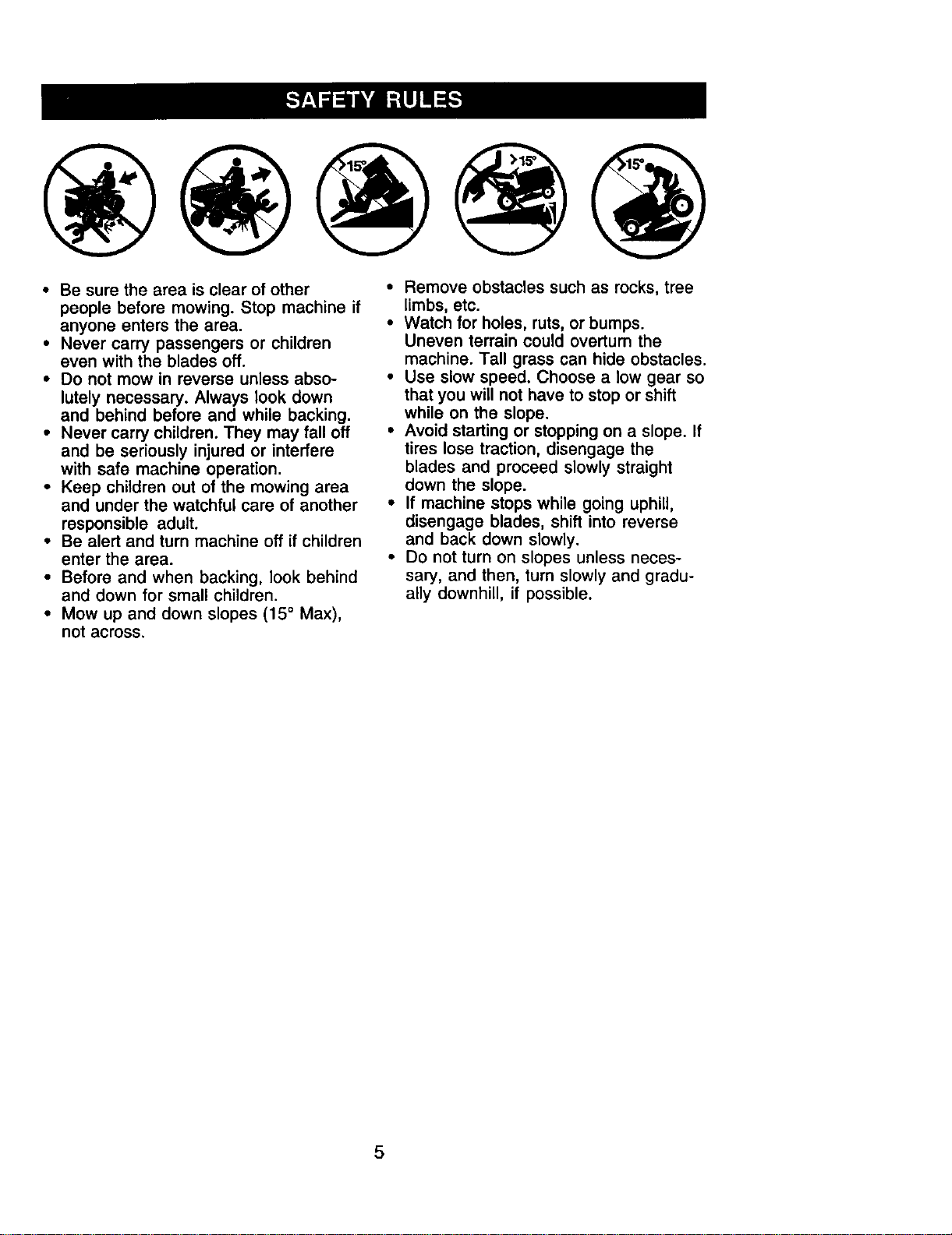
• Mow up and down slopes (15 ° Max),
not across,
• Remove obstacles such as rocks, tree
limbs, etc.
• Watch for holes, ruts, or bumps.
Uneven terrain could overturn the
machine. Tall grass can hide obstacles.
• Use slow speed. Choose a low gear so
that you will not have to stop or shift
while on the slope.
• Avoid starting or stopping on a slope. If
tires lose traction, disengage the
blades and proceed slowly straight
down the slope.
• If machine stops while going uphill,
disengage blades, shift into reverse
and back down slowly.
• Do not turn on slopes unless neces-
sary, and then, turn slowly and gradu-
ally downhill, if possible.
5
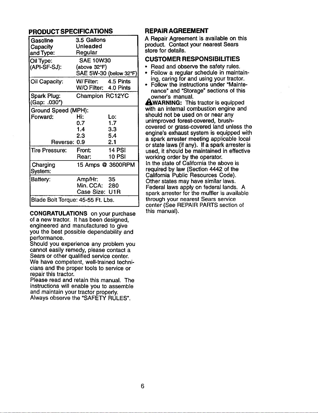
=RODUCT SPECIFICATIONS
Gasoline 3.5 Gallons
Capacity Unleaded
and Type: Regular
Oil Type: SAE 10W30
API-SF-SJ): (above 32°F)
SAE 5W-30 (below 32°F
Oil Capacity: W/Filter'. 4.5 Pints
W/O Filter: 4.0 Pints
Spark Plug: Champion RC12YC
(Gap: .030")
Ground Speed (MPH):
Forward: Hi: Lo:
0.7 1.7
1.4 3.3
2.3 5.4
Reverse: 0.9 2.1
]3re Pressure: Front: 14 PSI
Rear: 10 PSI
Charging 15 Amps @ 3600RPM
System:
Battery: Amp/Hr: 35
Min. CCA: 280
Case Size: U1R
Blade Bolt Torque: 45-55 Ft. Lbs.
CONGRATULATIONS on your purchase
of a new tractor. It has been designed,
engineered and manufactured to give
you the best possible dependability and
performance.
Should you experience any problem you
cannot easily remedy, please contact a
Sears or other qualified service center.
We have competent, well-trained techni-
cians and the proper tools to service or
repair this tractor.
Please read and retain this manual. The
instructions will enable you to assemble
and maintain your tractor properly.
Always observe the "SAFETY RULES".
REPAIR AGREEMENT
A Repair Agreement is available on this
product. Contact your nearest Sears
store for details.
CUSTOMER RESPONSIBILITIES
• Read and observe the safety rules.
• Follow a regular schedule in maintain-
ing, caring for and using your tractor.
• Follow the instructions under "Mainte-
nance" and "Storage" sections of this
owner's manual.
_W_,RNING: This tractor is equipped
with an internal combustion engine and
should not be used on or near any
unimproved forest-covered, brush-
covered or grass-covered land unless the
engine's exhaust system is equipped with
a spark arrester meeting applicable local
or state laws (if any). If a spark arrester is
used, it should be maintained in effective
working order by the operator.
In the state of California the above is
required by law (Section 4442 of the
California Public Resources Code).
Other states may have similar laws.
Federal laws apply on federal lands. A
spark arrester for the muffler is available
through your nearest Sears service
center (See REPAIR PARTS section of
this manual).
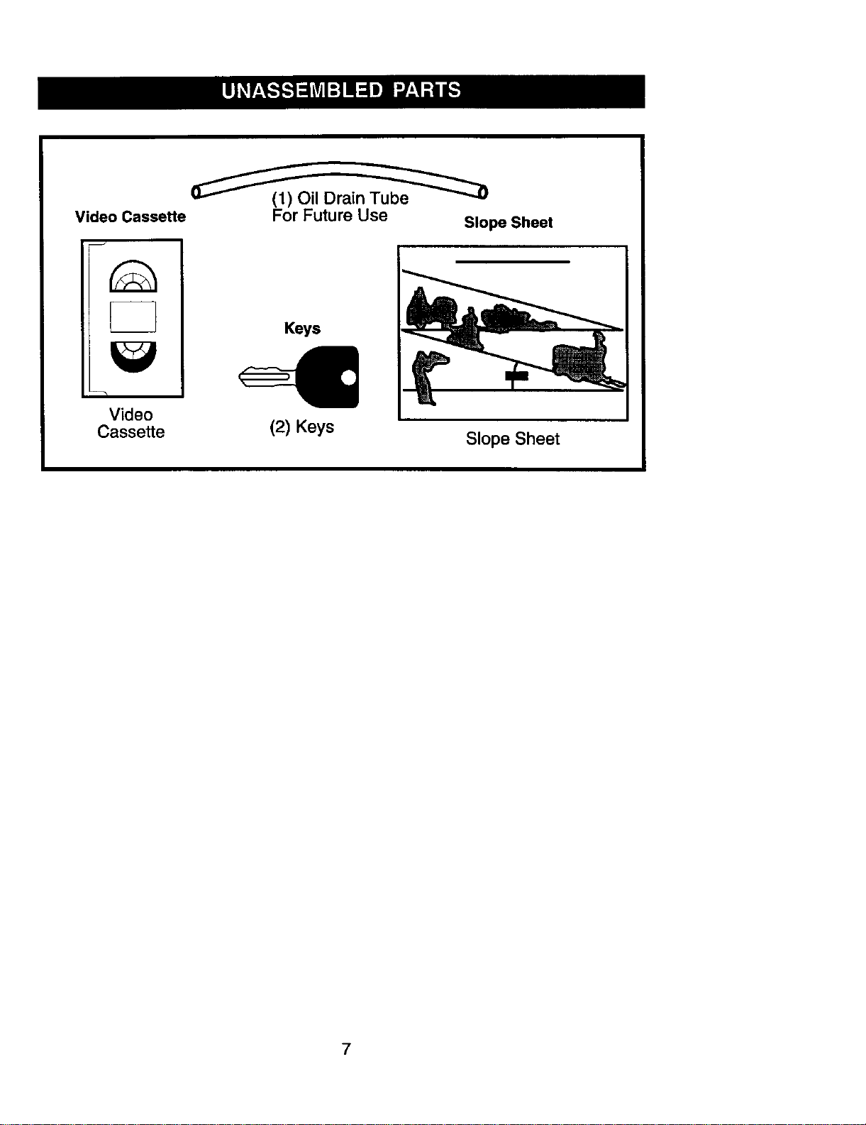
_Drain_
Video Cassette
Video
Cassette
For Future Use
Slope Sheet
Keys
(2) Keys
Slope Sheet
7
Your new tractor has been assembled at the factory. Review the video cassette before
you begin.
When right or left hand is mentioned in
this manual, it means, from your point of
view, when you are in the operating
position (seated behind the steering
wheel).
TO REMOVE TRACTOR FROM
CARTON
UNPACK CARTON
1. Cut, from top to bottom, along lines on
all four corners of carton, and lay
panels flat.
2. Remove packing materials.
3. Remove protective materials from
tractor hood and grille.
IMPORTANT: Check for and remove any
staplesin skid that may puncture tires
where tractor is to roll off skid.
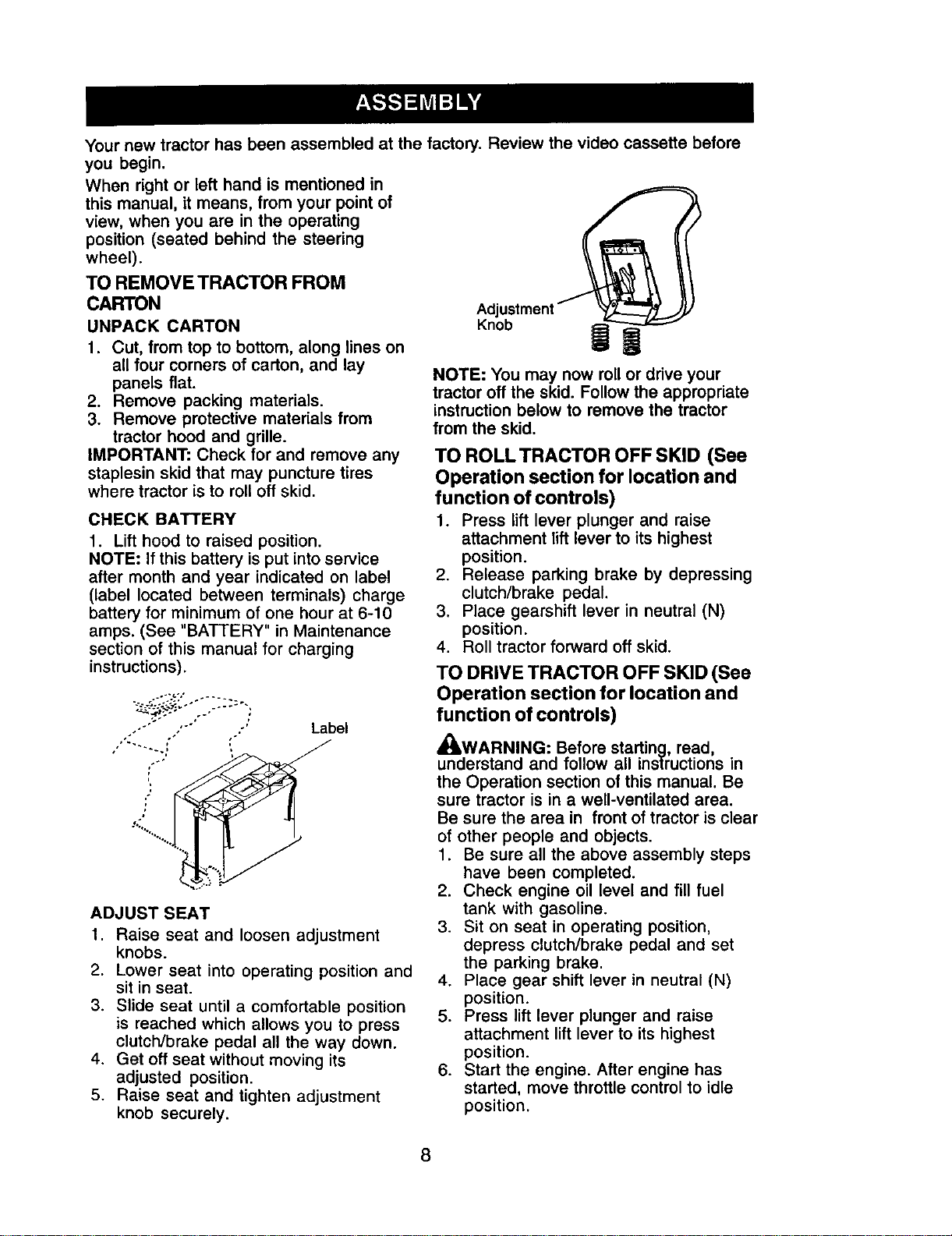
CHECK BATTERY
1. Lift hood to raised position.
NOTE: If this battery is put into service
after month and year indicated on label
(label located between terminals) charge
battery for minimum of one hour at 6-10
amps. (See "BATTERY" in Maintenance
section of this manual for charging
instructions).
;" ' ' Label
ADJUST SEAT
1. Raise seat and loosen adjustment
knobs.
2. Lower seat into operating position and
sit in seat.
3. Slide seat until a comfortable position
is reached which allows you to press
clutch/brake pedal all the way down.
4. Get off seat without moving its
adjusted position.
5. Raise seat and tighten adjustment
knob securely.
Knob
NOTE: You may now rollor drive your
tractor off the skid. Follow the appropriate
instruction below to remove the tractor
from the skid.
TO ROLLTRACTOR OFF SKID (See
Operation section for location and
function of controls)
1. Press lift lever plunger and raise
attachment lift lever to its highest
position.
2. Release parking brake by depressing
clutch/brake pedal.
3. Place gearshift lever in neutral (N)
position.
4. Roll tractor forward off skid.
TO DRIVE TRACTOR OFF SKID (See
Operation section for location and
function of controls)
_WARNING: Before starting, read,
understand and follow all instructions in
the Operation section of this manual• Be
sure tractor is in a well-ventilated area•
Be sure the area in front of tractor is clear
of other people and objects.
1. Be sure all the above assembly steps
have been completed.
2. Check engine oil level and fill fuel
tank with gasoline.
3. Sit on seat in operating position,
depress clutch/brake pedal and set
the parking brake.
4. Place gear shift lever in neutral (N)
position.
5. Press lift lever plunger and raise
attachment lift lever to its highest
position.
6. Start the engine. After engine has
started, move throttle control to idle
position.
8
7. Depress clutch/brake pedal into full
•BRAKE" position and hold. Move
gearshift lever to 1st gear.
8. Slowly release clutch/brake pedal and
slowly drive tractor off skid.
9. Apply brake to stop tractor, set parking
brake and place gearshift lever in
neutral position.
10.Turn ignition key to "STOP" position.
Continue with the instructions that follow.
CHECK TIRE PRESSURE
The tires on your tractor were overinflated
at the factory for shipping purposes.
Correct tire pressure is importantfor best
cutting performance.
• Reduce tire pressure to PSI shown in
"PRODUCT SPECIFICATIONS" section
of this manual.
CHECK MOWER LEVELNESS
For best cutting results, mower should be
properly leveled. See "TO LEVEL
MOWER HOUSING" in the Service and
Adjustments section of this manual.
CHECK FOR PROPER POSITION OF
ALL BELTS
See the figures that are shown for
replacing motion, mower drive, and
mower blade drive belts in the Service
and Adjustments section of this manual.
Verify that the belts are routed correctly.
CHECK BRAKE SYSTEM
After you learn how to operate your
tractor, check to see that the brake is
properly adjusted. See "TO ADJUST
BRAKE" in the Service and Adjustments
section of this manual.
CHECKLIST
Before you operate and enjoy your new
tractor, we wish to assure that you receive
the best performance and satisfaction
from this quality product.
Please review the following checklist:
/ All assembly instructions have been
completed.
,/No remaining loose parts in carton.
/ Battery is properly prepared and
charged. (Minimum 1 hour at 6 amps).
4 Seat is adjusted comfortably and
tightened securely.
/ All tires are properly inflated. (For
shipping purposes, the tires were
overinflated at the factory).
,/Be sure mower deck is properly leveled
side-to-side/front-to-rear for best cutting
results. (Tires must be properly inflated
for leveling).
,/Check mower and drive belts. Be sure
they are routed properly around pulleys
and inside all belt keepers.
J" Check wiring. See that all connections
are still secure and wires are properly
clamped.
While learning how to use your tractor,
pay extra attention to the following
important items:
,/Engine oil is at proper level.
,/Fuel tank is filled with fresh, clean,
regular unleaded gasoline.
,/Become familiar with all controls - their
location and function. Operate them
before you start the engine.
,/Be sure brake system is in safe operat-
ing condition.
9
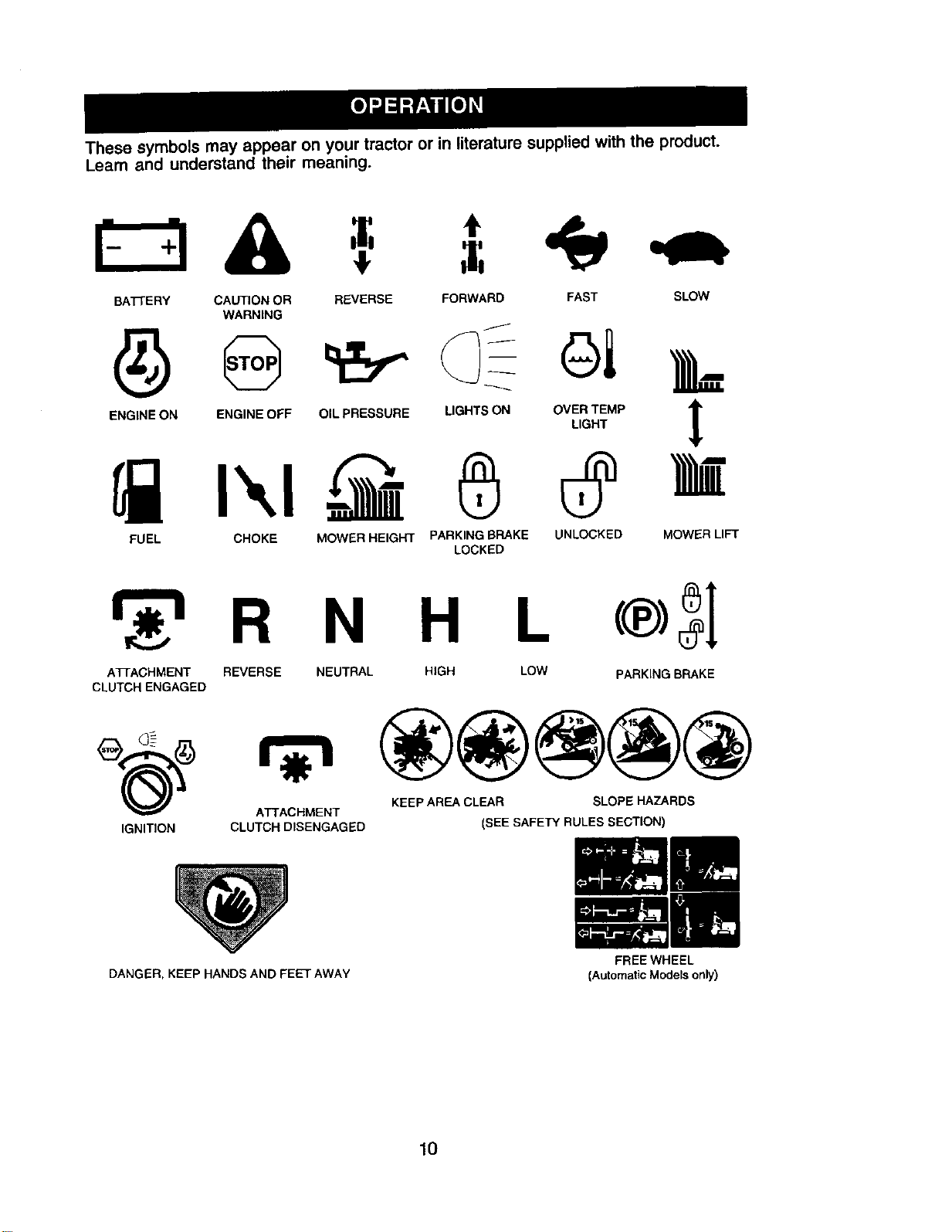
These symbols may appear on your tractor or in literature supplied with the product.
Learn and understand their meaning.
BATTERY CAUTION OR REVERSE FORWARD
WARNING
ENGINE ON ENGINE OFF OIL PRESSURE LIGHTS ON
FUEL CHOKE MOWER HEIGHT PARKING BRAKE
LOCKED
FAST SLOW
OI k
OV%_M. ]
UNLOCKED MOWER LIFT
R N H L
A33ACHMENT REVERSE NEUTRAL HIGH LOW PARKING BRAKE
CLUTCH ENGAGED
KEEP AREA CLEAR SLOPE HAZARDS
ATTACHMENT
IGNITION CLUTCH DISENGAGED (SEE SAFETY RULES SECTION)
DANGER, KEEP HANDS AND FEET AWAY
10
FREE WHEEL
(Automatic Models only)
KNOW YOUR TRACTOR
READ THIS OWNER'S MANUAL AND SAFETY RULES BEFORE OPERATING
YOUR TRACTOR
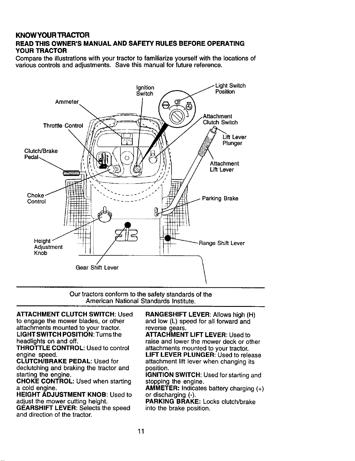
Compare the illustrations with your tractor to familiarize yourself with the locations of
various controls and adjustments. Save this manual for future reference.
Ammeter
Ignition Switch
Switch Position
Throttle Control Clutch Switch
Lift Lever
Plunger
Clutch/Brake
Attachment
Lift Lever
Choke
Control g Brake
Height ge Shift Lever
Adjustment
Knob
Gear Shift Lever \
\
Our tractors conform to the safety standards of the
American National Standards Institute.
ATTACHMENT CLUTCH SWITCH: Used
to engage the mower blades, or other
attachments mounted to your tractor.
LIGHTSWlTCH POSITION:Turnsthe
headlights on and off.
THRO'n'LE CONTROL: Used to control
engine speed.
CLUTCH/BRAKE PEDAL: Used for
declutching and braking the tractor and
starting the engine.
CHOKE CONTROL: Used when starting
a cold engine.
HEIGHT ADJUSTMENT KNOB: Used to
adjust the mower cutting height.
GEARSHIFT LEVER: Selects the speed
and direction of the tractor.
RANGESHIFT LEVER: Allows high (H)
and low (L) speed for all forward and
reverse gears.
ATTACHMENT LIFT LEVER: Used to
raise and lower the mower deck or other
attachments mounted to your tractor.
LIFT LEVER PLUNGER: Used to release
attachment lift lever when changing its
position.
IGNITION SWITCH: Used for starting and
stopping the engine.
AMMETER: Indicates battery charging (+)
or discharging (-).
PARKING BRAKE: Locks clutch/brake
into the brake position.
11
Theoperationofanytractorcan resultinforeign objects thrown into
the eyes, which can result in severe eye damage. Always wear
safety glasses or eye shields while operating your tractor or
performing any adjustments or repairs. We recommend standard
safety glasses or a wide vision safety mask worn over spectacles.
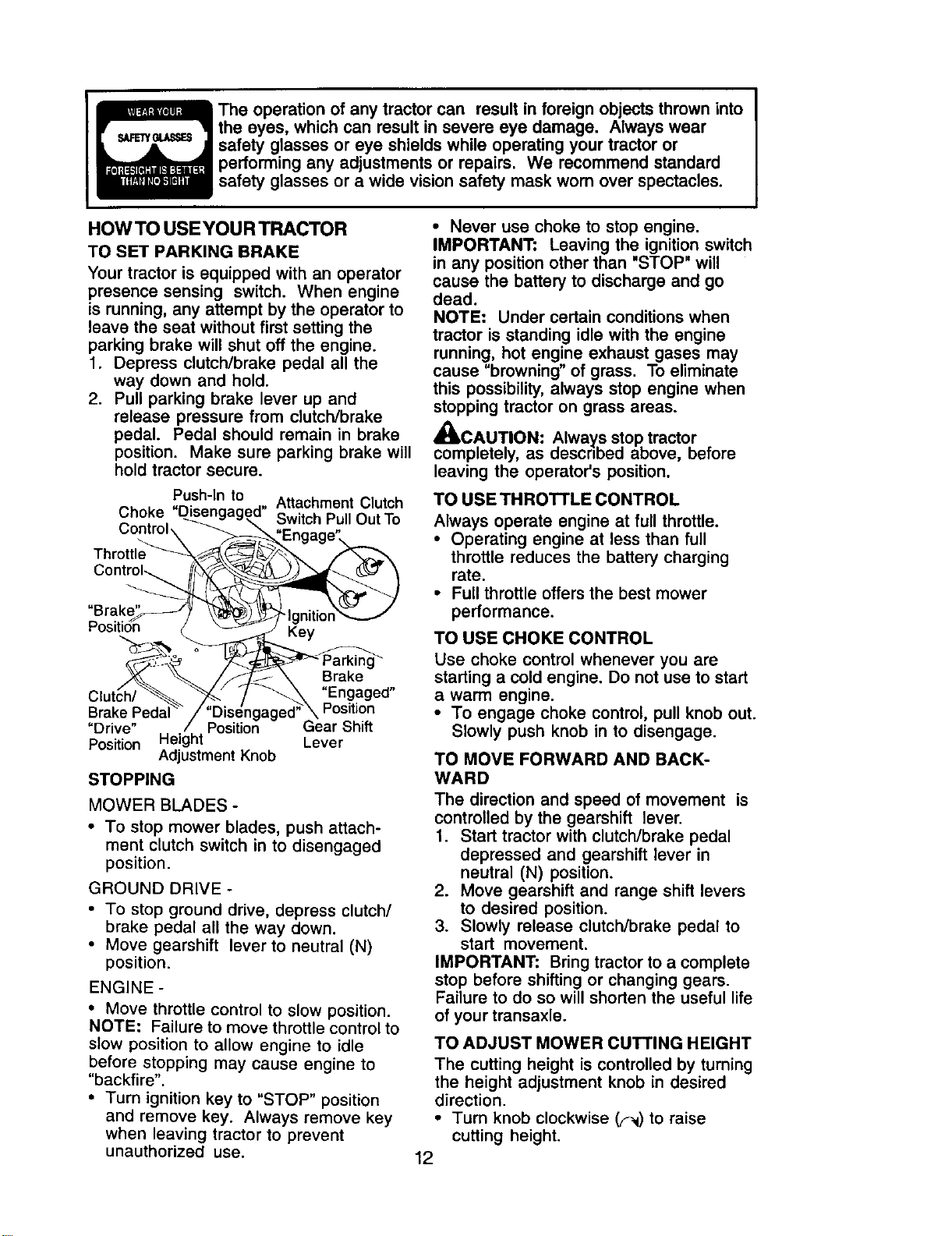
HOWTO USEYOURTRACTOR
TO SET PARKING BRAKE
Your tractor is equipped with an operator
presence sensing switch. When engine
is running, any attempt by the operator to
leave the seat without first setting the
parking brake will shut off the engine.
1. Depress clutch/brake pedal all the
way down and hold.
2. Pull parking brake lever up and
release pressure from clutch/brake
pedal. Pedal should remain in brake
position. Make sure parking brake will
hold tractor secure.
C' . P,.ush-ln to -, Attachment Clutch
noKe, ul_sengagea° Switch Pull Out To
Th rottIe_"__.. _ _",/_,
Contro,,.__ _._
Brak<_-_-J_ _-_ _-IanitionX__._ /
Position _ _ J I<ey
Clut_h/._._._,,..__/-_ En.gaged"
Brake Pedal"_/"Dis_ngaged;'_ Position
=Drive" / Position Gear Shift
Position Height Lever
Adjustment Knob
STOPPING
MOWER BLADES -
• To stop mower blades, push attach-
ment clutch switch in to disengaged
position.
GROUND DRIVE -
• To stop ground drive, depress clutch/
brake pedal all the way down.
• Move gearshift lever to neutral (N)
position.
ENGINE -
• Move throttle control to slow position.
NOTE: Failure to move throttle control to
slow position to allow engine to idle
before stopping may cause engine to
"backfire".
• Turn ignition key to "STOP" position
and remove key. Always remove key
when leaving tractor to prevent
unauthorized use.
• Never use choke to stop engine.
IMPORTANT: Leaving the ignition switch
in any position other than "STOP" will
cause the battery to discharge and go
dead.
NOTE: Under certain conditions when
tractor is standing idle with the engine
running, hot engine exhaust gases may
cause "browning" of grass. To eliminate
this possibility, always stop engine when
stopping tractor on grass areas.
_kCAUTION" Always stop tractor
completely, as descnbed above, before
leaving the operator's position.
TO USE THROTTLE CONTROL
Always operate engine at full throttle.
• Operating engine at less than full
throttle reduces the battery charging
rate.
• Full throttle offers the best mower
performance.
TO USE CHOKE CONTROL
Use choke control whenever you are
starting a cold engine. Do not use to start
a warm engine.
• To engage choke control, pull knob out.
Slowly push knob in to disengage.
TO MOVE FORWARD AND BACK-
WARD
The direction and speed of movement is
controlled by the gearshift lever.
1. Start tractor with clutch/brake pedal
depressed and gearshift lever in
neutral (N) position.
2. Move gearshift and range shift levers
to desired position.
3. Slowly release clutch/brake pedal to
start movement.
IMPORTANT: Bring tractor to a complete
stop before shifting or changing gears.
Failure to do so will shorten the useful life
of your transaxle.
TO ADJUST MOWER CUTTING HEIGHT
The cutting height is controlled by turning
the height adjustment knob in desired
direction.
• Turn knob clockwise (F_) to raise
cutting height.
12
• Turn knob counterclockwise (_)to
lower cutting height.
The cutting height range is approximately
1-1/2 =to 4-1/2". The heights are mea-
sured from the ground to the blade tip
with the engine not running. These
heights are approximate and may vary
depending upon soil conditions, height of
grass and types of grass being mowed.
• The average lawn should be cut to
approximately 2-1/2 inches during the
cool season and to over 3 inches
during hot months. For healthier and
better looking lawns, mow often and
after moderate growth.
• For best cutting performance, grass
over 6 inches in height should be
mowed twice. Make the first cut
relatively high; the second to desired
height.
TO ADJUST GAUGE WHEELS
Gauge wheels are properly adjusted
when they are slightly off the ground
when mower is at the desired cutting
height in operating position. Gauge
wheels then keep the deck in proper
position to help prevent scalping in most
terrain conditions.
NOTE: Be sure tractor is on a flat level
surface.
1. Lower mower and adjust mower to
desired cutting height.
2. Remove retainer spring and clevis pin
which secure each gauge wheel bar.
3. Lower gauge wheels to ground. Raise
gauge wheels slightly to align holes in
bracket and gauge wheel bar and
insert clevis pin. Gauge wheels
should be slightly off the ground.
4. Replace retainer spring into clevis pin.
5. Be sure all gauge wheels are in the
same setting.
IMPORTANT: Be sure to readjust gauge
wheels if you change the cutting height
of the mower deck.
Retainer f=
clevis
Pin
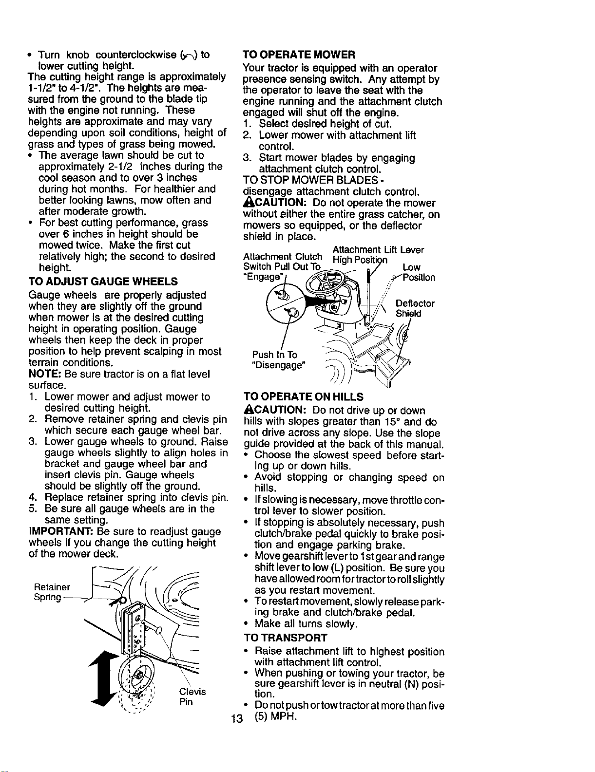
TO OPERATE MOWER
Your tractor is equipped with an operator
presence sensing switch. Any attempt by
the operator to leave the seat with the
engine running and the attachment clutch
engaged will shut off the engine.
1. Select desired height of cut.
2. Lower mower with attachment lift
control.
3. Start mower blades by engaging
attachment clutch control.
TO STOP MOWER BLADES -
disengage attachment clutch control.
_CAUTION: Do not operate the mower
without either the entire grass catcher, on
mowers so equipped, or the deflector
shield in place.
Attachment Lift Lever
Attachment Clutch HiahPosition
Switch Pull Out To__ _ ;,Y Low
Enga__ / ' ._fPosition
.S/
( Deflector
/d
"D,sengage" _'_)_
13
TO OPERATE ON HILLS
_CAUTION: Do not drive up or down
hills with slopes greater than 15° and do
not drive across any slope. Use the slope
guide provided at the back of this manual.
• Choose the slowest speed before start-
ing up or down hills.
• Avoid stopping or changing speed on
hills.
• Ifslowing is necessary, move throttle con-
trol lever to slower position.
• If stopping is absolutely necessary, push
clutch/brake pedal quickly to brake posi-
tion and engage parking brake.
• Move gearshift lever to 1st gear and range
shift lever to low (L) position. Be sure you
have allowed room for tractor toroll slightly
as you restart movement.
• To restart movement, slowly release park-
ing brake and clutch/brake pedal.
• Make all turns slowly.
TO TRANSPORT
• Raise attachment lift to highest position
with attachment lift control.
When pushing or towing your tractor, be
sure gearshift lever is in neutral (N) posi-
tion.
Do not push or tow tractor at more than five
(5) MPH.
NOTE: To protect hood from damage
when transporting your tractor on a truck
or a trailer, be sure hood is closed and
secured to tractor. Use an appropriate
means of tying hood to tractor (rope, cord,
etc.).
TOWING CARTS AND OTHER A'n'ACH-
MENTS
Tow only the attachments that are
recommended by and comply with
specifications of the manufacturer of your
tractor. Use common sense when towing.
Too heavy of a load, while on a slope, is
dangerous. Tires can lose traction with
the ground and cause you to lose control
of your tractor.
BEFORE STARTING THE ENGINE
CHECK ENGINE OIL LEVEL
The engine in your tractor has been
shipped, from the factory, already filled
with summer weight oil.
1. Check engine oil with tractor on level
ground.
2. Unthread and remove oil fill cap/
dipstick; wipe oil off. Reinsert the
dipstick into the tube and rest oil fill
cap on the tube. Do not thread the
cap onto the tube. Remove and read
oil level. If necessary, add oil until
"FULL" mark on dipstick is reached.
Do not overfill.
• For cold weather operation you should
change oil for easier starting (See "OIL
VISCOSITY CHART' in the Mainte-
nance section of this manual).
• To change engine oil, see the Mainte-
nance section in this manual.
ADD GASOLINE
• Fill fuel tank to bottom of filler neck. Do
not overfill. Use fresh, clean, regular
unleaded gasoline with a minimum of
87 octane. (Use of leaded gasoline
will increase carbon and lead oxide
deposits and reduce valve life). Do not
mix oil with gasoline. Purchase fuel in
quantities that can be used within 30
days to assure fuel freshness.
,_CAUTION: Wipe off any spilled oil or
fuel. Do not store, spill or use gasoline
near an open flame.
IMPORTANT: When operating in
temperatures below32°F(0°C), use fresh,
clean winter grade gasoline to help
insure good cold weather starting.
_CAUTION: Alcohol blended fuels
(called gasohol or using ethanol or
methanol) can attract moisture which
leads to separation and formation of
acids during storage. Acidic gas can
damage the fuel system of an engine
while in storage. To avoid engine
problems, the fuel system should be
emptied before storage of 30 days or
longer. Drain the gas tank, start the
engine and let it run until the fuel lines
and carburetor are empty. Use fresh fuel
next season. See Storage Instructions for
additional information. Never use engine
or carburetor cleaner products in the fuel
tank or permanent damage may occur.
TO START ENGINE
When starting the engine for the first time or if
the engine has run out of fuel, it willtake extra
cranking time to move fuel from the tank to
the engine.
1. Sit on seat in operating position,
depress clutch/brake pedal and set
parking brake.
2. Place gear shift lever in neutral (N)
position.
3. Move attachment clutch to disen-
gaged position.
4. Move throttle control to fast position
5. Pull choke control out for a cold
engine start attempt. For a warm
engine start attempt the choke control
may not be needed.
NOTE: Before starting, read the warm and
cold starting procedures below.
6. Insert key into ignition and turn key
clockwise to start position and release
key as soon as engine starts. Do not
run starter continuously for more than
fifteen seconds per minute. If the
engine does not start after several
attempts, push choke control in, wait a
few minutes and try again. If engine
still does not start, pull the choke
control out and retry,
WARM WEATHER STARTING (50° F and
above)
7. When engine starts, slowly push
choke control in until the engine
begins to run smoothly. If the engine
starts to run roughly, pull the choke
control out slightly for a few seconds
and then continue to push the control
in slowly.
• The attachments and ground drive can
now be used. If the engine does not
accept the load, restart the engine and
allow it to warm up for one minute
using the choke as described above.
14
COLD WEATHER STARTING (50 ° F and
below)
7. When engine starts, slowly push
choke control in until the engine
begins to run smoothly. Continue to
push the choke control in small steps
allowing the engine to accept small
changes in speed and load, until the
choke control is fully in. If the engine
starts to run roughly, pull the choke
control out slightly for a few seconds
and then continue to push the control
in slowly. This may require an engine
warm-up period from several seconds
to several minutes, depending on the
temperature.
• The attachments can be used during
the engine warm-up period and may
require the choke control be pulled out
slightly.
NOTE, Ifat a high altitude (above 3000 feet)
or in cold temperatures (below 32 F) the
carburetor fuel mixture may need to be
adjusted for best engine performance (see
"TO ADJUST CARBURETOR" in the Service
and Adjustments section of this manual).
MOWING TIPS
• Tire chains cannot be used when the
mower housing is attached to tractor.
• Mower should be properly leveled for
best mowing performance. See 'q'O
LEVEL MOWER HOUSING" in the
Service and Adjustments section of this
manual.
• The left hand side of mower should be
used for trimming.
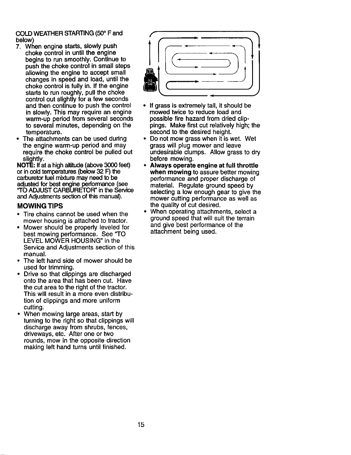
• Drive so that clippings are discharged
onto the area that has been cut. Have
the cut area to the right of the tractor.
This will result in a more even distribu-
tion of clippings and more uniform
cutting.
• When mowing large areas, start by
turning to the right so that clippings will
discharge away from shrubs, fences,
driveways, etc. After one or two
rounds, mow in the opposite direction
making left hand turns until finished.
f I
Jl
)
If grass is extremely tall, it should be
mowed twice to reduce load and
possible fire hazard from dried clip-
pings. Make first cut relatively high; the
second to the desired height.
Do not mow grass when it is wet. Wet
grass will plug mower and leave
undesirable clumps. Allow grass to dry
before mowing.
Always operate engine at full throttle
when mowing to assure better mowing
performance and proper discharge of
material. Regulate ground speed by
selecting a low enough gear to give the
mower cutting performance as well as
the quality of cut desired.
When operating attachments, select a
ground speed that will suit the terrain
and give best performance of the
attachment being used.
15
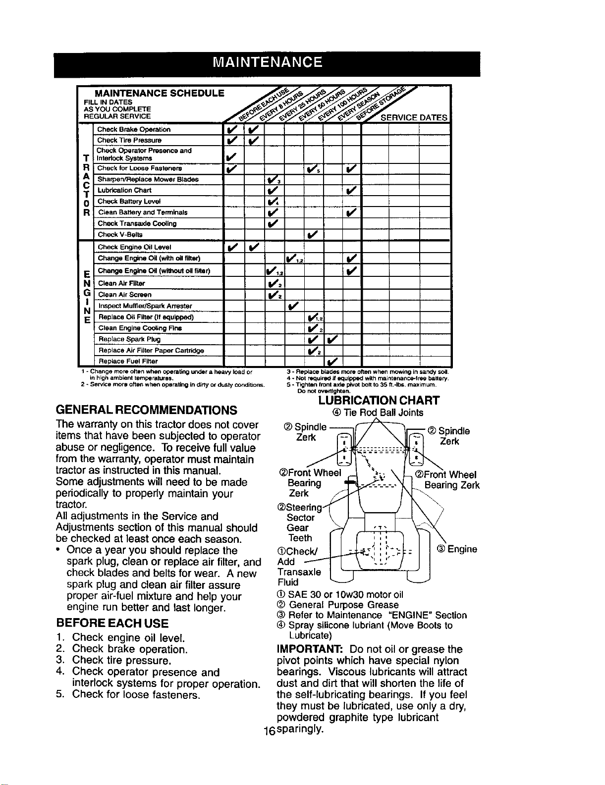
MAINTENANCE SCHEDULE L_"/"._/_._. _"_..._ J,_ p'
RE O RSERV,OE f F Z/ / / y y TsEnv,oE o rEs
Chec,ora.o.,--Check "13rePressure
Check Operator Presence and
T Intedock Systems If
R Check for Loose Fasteners tf V's Ik_
Sharpen/Replace Mower Blades _1_
T Lubrication Chart If
0 Check Battery Level 1_4
R C_een Battery and Terminals If V /
Check Transaxle Cooling v"
Check V-Belts If
Check Engine Oil Level I_ I_
Change Engine Oil (with oil filter) I1111r= ll_
E Change Engine Oil (without Oilfilter) _hl_1,2 _i_
N CalanAIr FiRer _I_':
G Clean Air Screen
NI Inspect Muffler/Spark
Arrestsr
l/
E Replace Oil Filter (If equipped) I_1.=
Clean Engine Cooling Fine 1_2
Replace Spark Plug _#z If
Replace/,Jr Filter Paper Cartridge
Replace Fuel Fitter
1 - Change more often when opetattng under a heavy load ot
in high ambient temperatures,
2 - Sen/ice m_ro often when oporettng in _rty or dusty conditions.
GENERAL RECOMMENDATIONS
The warranty on this tractor does not cover
items that have been subjected to operator
abuse or negligence. To receive full value
from the warranty, operator must maintain
tractor as instructed in this manual.
Some adjustments will need to be made
periodically to properly maintain your
tractor.
All adjustments in the Service and
Adjustments section of this manual should
be checked at least once each season.
• Once a year you should replace the
spark plug, clean or replace air filter, and
check blades and belts for wear. A new
spark plug and clean air filter assure
proper air-fuel mixture and help your
engine run better and last longer.
BEFORE EACH USE
1. Check engine oil level.
2. Check brake operation.
3. Check tire pressure.
4. Check operator presence and
interlock systems for proper operation.
5. Check for loose fasteners.
3 - Rep4ace blades more often when mowing in sandy soil.
4 - Not required if equipped with maintenance*lree battery.
5 - Tighten front axle pivot bolt to 35 flabs, maximum.
Do no_ overtlght on.
LUBRICATION CHART
® Tie Rod Ball Joints
Spindle
Zerk Zerk
(_Front Wheel
Bearing Bearing Zerk
Zerk
_)Steedn
Sector
Gear
Teeth
(_Check/ @Engine
Add
Transaxle
Fluid
_) SAE 30 or 10w30 motor oil
(_ General Purpose Grease
@ Refer to Maintenance "ENGINE" Section
(_ Spray silicone lubriant(Move Bootsto
Lubricate)
IMPORTANT: Do not oil or grease the
pivot points which have special nylon
bearings. Viscous lubricants will attract
dust and dirt that will shorten the life of
the self-lubricating bearings. If you feel
they must be lubricated, use only a dry,
powdered graphite type lubricant
16sparingly.
TRACTOR
Always observe safety rules when
performing any maintenance.
BRAKE OPERATION
If tractor requires more than six (6) feet
stopping distance at high speed in
highest gear, then brake must be ad-
justed. (See "TO ADJUST BRAKE" in the
Service and Adjustments section of this
manual).
TIRES
• Maintain proper air pressure in all tires
(See "PRODUCT SPECIFICATIONS"
section of this manual).
• Keep tires free of gasoline, oil, or insect
control chemicals which can harm
rubber.
• Avoid stumps, stones, deep ruts, sharp
objects and other hazards that may
cause tire damage.
NOTE: To seal tire punctures and prevent
flat tires due to slow leaks, tire sealant
may be purchased from your local parts
dealer. Tire sealant also prevents tire dry
rot and corrosion.
OPERATOR PRESENCE SYSTEM
Be sure operator presence and interlock
systems are working properly. If your
tractor does not function as described,
repair the problem immediately.
• The engine should not start unless the
clutch/brake pedal is fully depressed
and attachement clutch control is in the
disengaged position.
• When the engine is running, any
attempt by the operator to leave the
seat without first setting the parking
brake should shut off the engine.
• When the engine is running and the
attachment clutch is engaged, any
attempt by the operator to leave the
seat should shut off the engine.
• The attachment clutch should never
operate unless the operator is in the
seat.
BLADE CARE
For best results mower blades must be
kept sharp. Replace bent or damaged
blades.
BLADE REMOVAL
1. Raise mower to highest position to
allow access to blades.
NOTE: Protect your hands with gloves
and/or wrap blade with heavy cloth.
2. Remove blade bolt by turning counter-
clockwise.
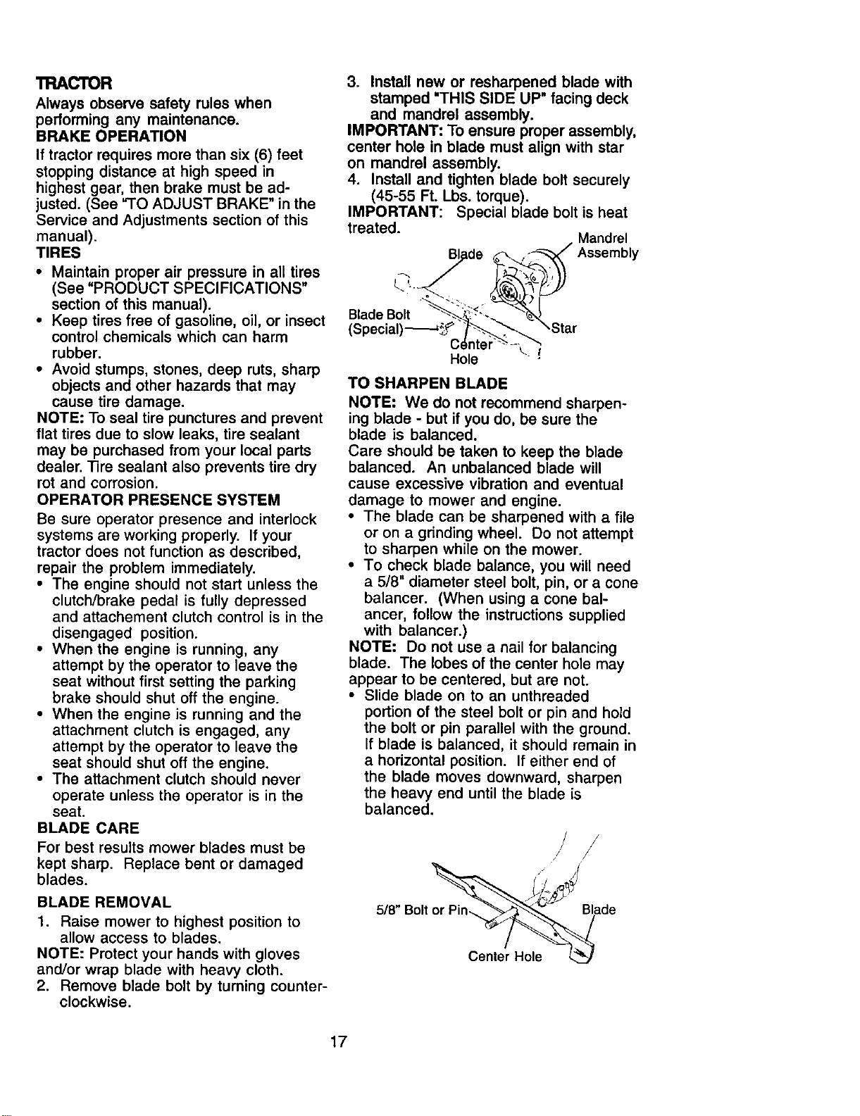
3. Install new or resharpened blade with
stamped "THIS SIDE UP" facing deck
and mandrel assembly.
IMPORTANT: To ensure proper assembly,
center hole in blade must align with star
on mandrel assembly.
4. Install and tighten blade bolt securely
(45-55 Ft. Lbs. torque).
IMPORTANT: Special blade bolt is heat
treated.
Mandrel
Assembly
Blade Bolt
(Speciall
C=
\.!
Hole
TO SHARPEN BLADE
NOTE: We do not recommend sharpen-
ing blade - but if you do, be sure the
blade is balanced.
Care should be taken to keep the blade
balanced. An unbalanced blade will
cause excessive vibration and eventual
damage to mower and engine.
• The blade can be sharpened with a file
or on a grinding wheel. Do not attempt
to sharpen while on the mower.
• To check blade balance, you will need
a 5/8" diameter steel bolt, pin, or a cone
balancer. (When using a cone bal-
ancer, follow the instructions supplied
with balancer.)
NOTE: Do not use a nail for balancing
blade. The lobes of the center hole may
appear to be centered, but are not.
• Slide blade on to an unthreaded
portion of the steel bolt or pin and hold
the bolt or pin parallel with the ground.
If blade is balanced, it should remain in
a horizontal position. If either end of
the blade moves downward, sharpen
the heavy end until the blade is
balanced.
/ /
5/8" Bolt o_ade
Center Hole
17
BATTERY
Your tractor has a battery charging system
which is sufficient for normal use. How-
ever, periodic charging of the battery with
an automotive charger will extend its life.
• Keep battery and terminals clean.
• Keep battery bolts tight.
• Keep small vent holes open.
• Recharge at 6-10 amperes for 1 hour.
NOTE: The original equipment battery on
your tractor is maintenance free. Do not
attempt to open or remove caps or covers.
Adding or checking level of electrolyte is
not necessary.
TO CLEAN BA'I-FERY AND TERMINALS
Corrosion and dirt on the battery and
terminals can cause the battery to "leak"
power.
1. Remove terminal guard.
2. Disconnect BLACK battery cable first
then RED battery cable and remove
battery from tractor.
3. Rinse the battery with plain water and
dry.
4. Clean terminals and battery cable ends
with wire brush until bright.
5. Coat terminals with grease or petro-
leum jelly.
6. Reinstall battery (See "REPLACING
BAI-IERY" in the SERVICE AND
ADJUSTMENTS section of this
manual).
TRANSAXLE COOLING
Keep transaxle free from build-up of dirt
and chaff which can restrict cooling.
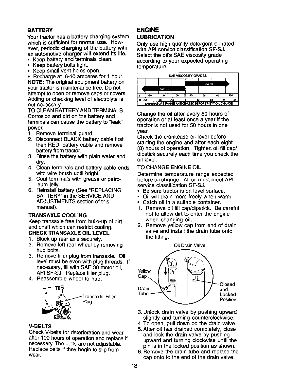
CHECK TRANSAXLE OIL LEVEL
1. Block up rear axle securely.
2. Remove left rear wheel by removing
hub bolts.
3. Remove filler plug from transaxle. Oil
level must be even with plug threads. If
necessary, fill with SAE 30 motor oil,
API SF-SJ. Replace filler plug.
4. Reassemble wheel to hub.
Transaxle
Plug
Filler
V-BELTS
Check V-belts for deterioration and wear
after 100 hours of operation and replace if
necessary. The belts are not adjustable.
Replace belts if they begin to slip from
wear.
ENGINE
LUBRICATION
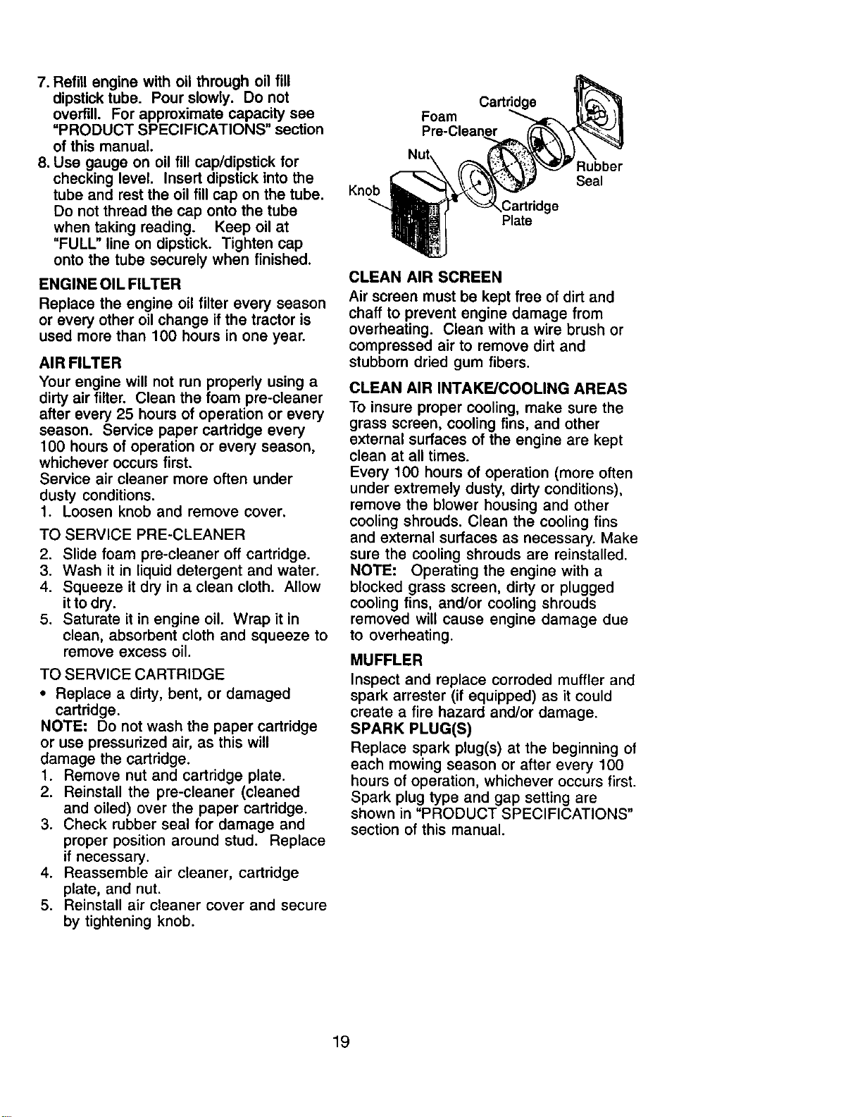
Only use high quality detergent oil rated
with API service classification SF-SJ.
Select the oil's SAE viscosity grade
according to your expected operating
temperature.
Change the oil after every 50 hours of
operation or at least once a year if the
tractor is not used for 50 hours in one
year.
Check the crankcase oil level before
starting the engine and after each eight
(8) hours of operation. Tighten oil fill cap/
dipstick securely each time you check the
oil level.
TO CHANGE ENGINE OIL
Determine temperature range expected
before oil change. All oil must meet API
service classification SF-SJ.
• Be sure tractor is on level surface.
• Oil will drain more freely when warm.
• Catch oil in a suitable container.
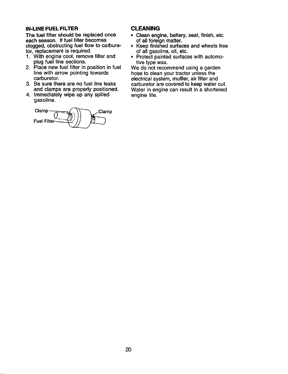
1. Remove oil fill cap/dipstick. Be careful
not to allow dirt to enter the engine
when changing oil
2. Remove yellow cap from end of drain
valve and install the drain tube onto
the fitting.
Oil Drain Valve
Dur_ien----_Yellow / 1 _ _ -Cap_
_ Closed
and
Locked
Position
3. Unlock drain valve by pushing upward
slightly and turning counterclockwise.
4. To open, pull down on the drain valve.
5. After oil has drained completely, close
and lock the drain valve by pushing
upward and turning clockwise until the
pin is in the locked position as shown.
6. Remove the drain tube and replace the
cap onto to the end of the drain valve.
18
7. Refill engine with oil through oil fill
dipstick tube. Pour slowly. Do not
overfill. For approximate capacity see
"PRODUCT SPECIFICATIONS" section
of this manual.
8. Use gauge on oil fill cap/dipstick for
checking level. Insert dipstick into the
tube and rest the oil fill cap on the tube.
Do not thread the cap onto the tube
when taking reading. Keep oil at
"FULL" line on dipstick. Tighten cap
onto the tube securely when finished.
ENGINE OIL FILTER
Replace the engine oil filter every season
or every other oil change if the tractor is
used more than 100 hours in one year.
AIR FILTER
Your engine will not run properly using a
dirty air filter. Clean the foam pre-cleaner
after every 25 hours of operation or every
season. Service paper cartridge every
100 hours of operation or every season,
whichever occurs first.
Service air cleaner more often under
dusty conditions.
1. Loosen knob and remove cover.
TO SERVICE PRE-CLEANER
2. Slide foam pre-cleaner off cartridge.
3. Wash it in liquid detergent and water.
4. Squeeze it dry in a clean cloth. Allow
it to dry.
5. Saturate it in engine oil. Wrap it in
clean, absorbent cloth and squeeze to
remove excess oil.
TO SERVICE CARTRIDGE
• Replace a dirty, bent, or damaged
cartridge.
NOTE: Do not wash the paper cartridge
or use pressurized air, as this will
damage the cartridge.
1. Remove nut and cartridge plate.
2. Reinstall the pre-cleaner (cleaned
and oiled) over the paper cartridge.
3. Check rubber seal for damage and
proper position around stud. Replace
if necessary.
4. Reassemble air cleaner, cartridge
plate, and nut.
5. Reinstall air cleaner cover and secure
by tightening knob.
Knob
Foam
Cartddge
Plate
Rubber
Seal
go
CLEAN AIR SCREEN
Air screen must be kept free of dirt and
chaff to prevent engine damage from
overheating. Clean with a wire brush or
compressed air to remove dirt and
stubborn dried gum fibers.
CLEAN AIR INTAKE/COOLING AREAS
To insure proper cooling, make sure the
grass screen, cooling fins, and other
external surfaces of the engine are kept
clean at all times.
Every 100 hours of operation (more often
under extremely dusty, dirty conditions),
remove the blower housing and other
cooling shrouds. Clean the cooling fins
and external surfaces as necessary. Make
sure the cooling shrouds are reinstalled.
NOTE: Operating the engine with a
blocked grass screen, dirty or plugged
cooling fins, and/or cooling shrouds
removed will cause engine damage due
to overheating.
MUFFLER
Inspect and replace corroded muffler and
spark arrester (if equipped) as it could
create a fire hazard and/or damage.
SPARK PLUG(S)
Replace spark plug(s) at the beginning of
each mowing season or after every 100
hours of operation, whichever occurs first.
Spark plug type and gap setting are
shown in "PRODUCT SPECIFICATIONS"
section of this manual.
19
IN-LINE FUEL FILTER
The fuel filter should be replaced once
each season. If fuel filter becomes
clogged, obstructing fuel flow to carbure-
tor, replacement is required.
1. With engine cool, remove filter and
plug fuel line sections.
2. Place new fuel filter in position in fuel
line with arrow pointing towards
carburetor.
3. Be sure there are no fuel line leaks
and clamps are properly positioned.
4. immediately wipe up any spilled
gasoline.
Clamp_mp
Fuel Filter_
CLEANING
• Clean engine, battery, seat, finish, etc.
of all foreign matter.
• Keep finished surfaces and wheels free
of all gasoline, oil, etc.
• Protect painted surfaces with automo-
tive type wax.
We do not recommend using a garden
hose to clean your tractor unless the
electrical system, muffler, air filter and
carburetor are covered to keep water out.
Water in engine can result in a shortened
engine life.
20
A
WARNING: TO AVIOD SERIOUS INJURY, BEFORE PERFORMING ANY
SERVICE OR ADJUSTMENTS:
1. Depress clutch/brake pedal fully and set parking brake.
2. Place gearshift lever in neutral (N) position.
3. Place attachment clutch in =DISENGAGED" position.
4. Turn ignition key to =STOP" and remove key.
5. Make sure the blades and all moving parts have completely stopped.
6. Disconnect spark plug wire from spark plug and place wire where it cannot
come in contact with plug.
TRACTOR
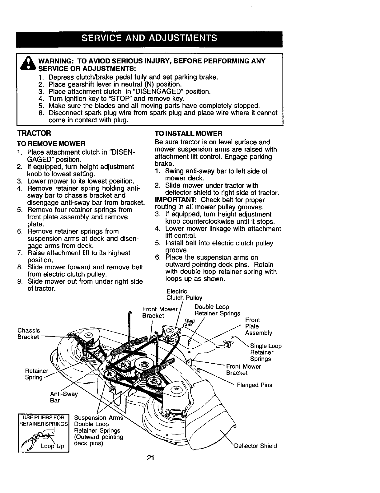
TO REMOVE MOWER
1. Place attachment clutch in "DISEN-
GAGED" position.
2. If equipped, turn height adjustment
knob to lowest setting.
3. Lower mower to its lowest position.
4. Remove retainer spring holding anti-
sway bar to chassis bracket and
disengage anti-sway bar from bracket.
5. Remove four retainer springs from
front plate assembly and remove
plate.
6. Remove retainer springs from
suspension arms at deck and disen-
gage arms from deck.
7. Raise attachment lift to its highest
position.
8. Slide mower forward and remove belt
from electric clutch pulley.
9. Slide mower out from under right side
of tractor.
Chassis
Bracket
Retainer
Spring
Anti-Sway
Bar
TO INSTALL MOWER
Be sure tractor is on level surface and
mower suspension arms are raised with
attachment lift control. Engage parking
brake.
1. Swing anti-sway bar to left side of
mower deck.
2. Slide mower under tractor with
deflector shield to right side of tractor.
IMPORTANT: Check belt for proper
routing in all mower pulley grooves.
3. If equipped, turn height adjustment
knob counterclockwise until it stops.
4. Lower mower linkage with attachment
lift control.
5. Install belt into electric clutch pulley
groove.
6. Place the suspension arms on
outward pointing deck pins. Retain
with double loop retainer spring with
loops up as shown.
Electric
Clutch Pulley
Front Mower Double Loop
Bracket Retainer Springs
Front
Plate
Assembly
Single Loop
Retainer
Springs
Mower
Bracket
Flanged Pins
USE PLIERS FOR
RETAINER/_upSPRINGS
Suspension Arm
Double Loop
Retainer Springs
(Outward pointing
deck pins)
21
'Deflector Shield
7. Install front plate assembly to tractor
suspension brackets and retain with
single loop retainer springs as shown.
8. Position front plate assembly between
front mower brackets. Raise deck and
plate assembly to align holes and
insert flanged pins. Secure pins with
double loop retainer springs between
the plate and mower brackets.
NOTE: To assist in locating hole in
flanged pin, the hole in pin is inline with
notch on head of pin. If necessary, move
mower side-to-side to give space
between plate and mower brackets.
IMPORTANT: Check belt for proper
routing in all mower pulley grooves.
9. Connect anti-sway bar to chassis
bracket under left footrest and retain
with double loop retainer spring.
10.If equipped, turn height adjustment
knob clockwise to remove slack from
mower suspension.
11.Raise deck to highest position.
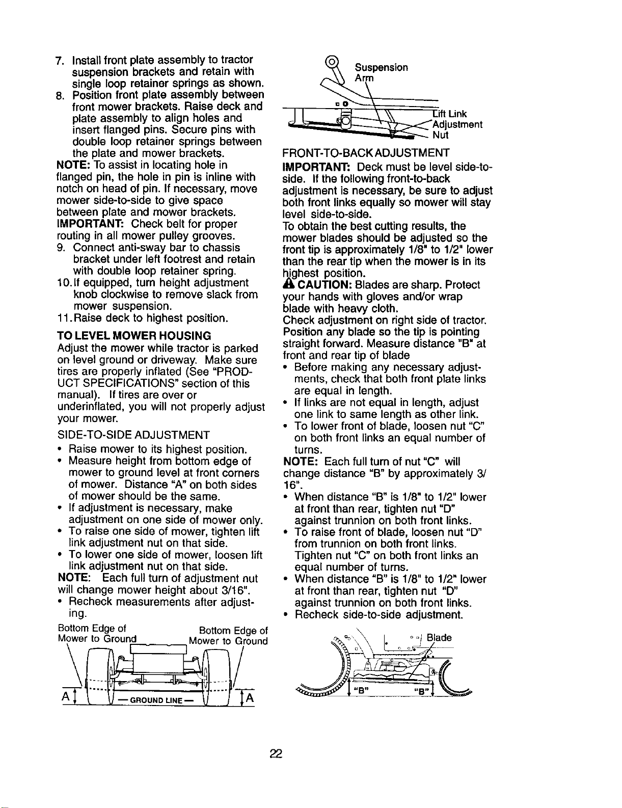
TO LEVEL MOWER HOUSING
Adjust the mower while tractor is parked
on level ground or driveway. Make sure
tires are properly inflated (See "PROD-
UCT SPECIFICATIONS" section of this
manual). If tires are over or
underinflated, you will not properly adjust
your mower.
SIDE-TO-SIDE ADJUSTMENT
• Raise mower to its highest position.
• Measure height from bottom edge of
mower to ground level at front corners
of mower. Distance "A" on both sides
of mower should be the same.
• If adjustment is necessary, make
adjustment on one side of mower only.
• To raise one side of mower, tighten lift
link adjustment nut on that side.
• To lower one side of mower, loosen lift
link adjustment nut on that side.
NOTE: Each full turn of adjustment nut
will change mower height about 3/16".
• Recheck measurements after adjust-
ing.
Bottom Edge of Bottom Edge of
Mower to Ground Mower to Ground
_e Ar_SUspensi°n
I I _ \\ Lift Link
_,,_:;::__=_- Adj ustment
_Nut
FRONT-TO-BACK ADJUSTMENT
IMPORTANT: Deck must be level side-to-
side. If the following front-to-back
adjustment is necessary, be sure to adjust
both front links equally so mower will stay
level side-to-side.
To obtain the best cutting results, the
mower blades should be adjusted so the
front tip is approximately 1/8" to 1/2" lower
than the rear tip when the mower is in its
_ghest position.
CAUTION: Blades are sharp. Protect
your hands with gloves and/or wrap
blade with heavy cloth.
Check adjustment on right side of tractor.
Position any blade so the tip is pointing
straight forward. Measure distance "B" at
front and rear tip of blade
• Before making any necessary adjust-
ments, check that both front plate links
are equal in length.
• If links are not equal in length, adjust
one link to same length as other link.
• To lower front of blade, loosen nut "C"
on both front links an equal number of
turns.
NOTE: Each full turn of nut "C" will
change distance "B" by approximately 3/
16".
• When distance "B" is 1/8" to 1/2" lower
at front than rear, tighten nut "D"
against trunnion on both front links.
• To raise front of blade, loosen nut "D"
from trunnion on both front links.
Tighten nut "C" on both front links an
equal number of turns.
• When distance "B" is 1/8" to 1/2" lower
at front than rear, tighten nut "D"
against trunnion on both front links.
• Recheck side-to-side adjustment.
\
Blade
"B.... e"
22
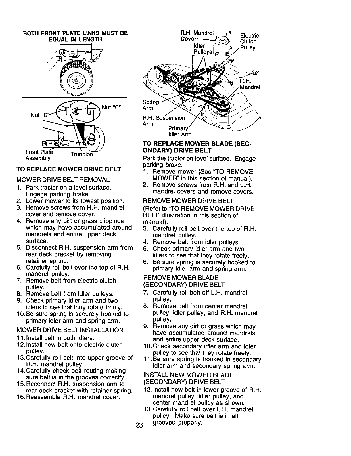
BOTH FRONT PLATE LINKS MUST BE
EQUAL IN LENGTH
R.H. Mandrel t _ Electric
Clutch
Idler
a.H.
.Mandrel
Nut
Nut "C"
Front Plate Trunnion
Assembly
TO REPLACE MOWER DRIVE BELT
MOWER DRIVE BELT REMOVAL
1. Park tractor on a level surface.
Engage parking brake.
2. Lower mower to its lowest position.
3. Remove screws from R.H. mandrel
cover and remove cover.
4. Remove any dirt or grass clippings
which may have accumulated around
mandrels and entire upper deck
surface.
5. Disconnect R.H. suspension arm from
rear deck bracket by removing
retainer spring.
6. Carefully roll belt over the top of R.H.
mandrel pulley.
7. Remove belt from electric clutch
pulley.
8. Remove belt from idler pulleys.
9. Check primary idler arm and two
idlers to see that they rotate freely.
10.Be sure spring is securely hooked to
primary idler arm and spring arm.
MOWER DRIVE BELT INSTALLATION
11.Install belt in both idlers.
12.Install new belt onto electric clutch
pulley.
13.Carefully roll belt into upper groove of
R.H. mandrel pulley.
14.Carefully check belt routing making
sure belt is in the grooves correctly.
15.Reconnect R.H. suspension arm to
rear deck bracket with retainer spring.
16. Reassemble R.H. mandrel cover.
Arm
R.H. Suspension
Arm
Idler Arm
TO REPLACE MOWER BLADE (SEC-
ONDARY) DRIVE BELT
Park the tractor on level surface. Engage
parking brake.
1. Remove mower (See "TO REMOVE
MOWER" in this section of manual).
2. Remove screws from R.H. and L.H.
mandrel covers and remove covers.
REMOVE MOWER DRIVE BELT
(Refer to "TO REMOVE MOWER DRIVE
BELT" illustration in this section of
manual).
3. Carefully roll belt over the top of R.H.
mandrel pulley.
4. Remove belt from idler pulleys.
5. Check primary idler arm and two
idlers to see that they rotate freely.
6. Be sure spring is securely hooked to
primary idler arm and spring arm.
REMOVE MOWER BLADE
(SECONDARY) DRIVE BELT
7. Carefully roll belt off L.H. mandrel
pulley.
8. Remove belt from center mandrel
pulley, idler pulley, and R.H. mandrel
pulley.
9. Remove any dirt or grass which may
have accumulated around mandrels
and entire upper deck surface.
10.Check secondary idler arm and idler
pulley to see that they rotate freely.
11 .Be sure spring is hooked in secondary
idler arm and secondary spring arm.
INSTALL NEW MOWER BLADE
(SECONDARY) DRIVE BELT
12.Install new belt in lower groove of R.H.
mandrel pulley, idler pulley, and
center mandrel pulley as shown.
13.Carefully roll belt over L.H. mandrel
pulley. Make sure belt is in all
23 grooves properly.
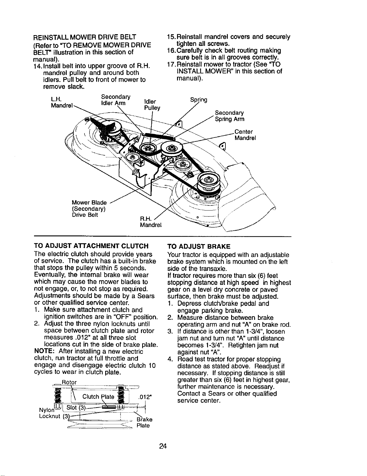
REINSTALLMOWERDRIVEBELT
(Referto =TOREMOVEMOWERDRIVE
BELT"illustrationinthissectionof
manual).
14.Installbeltintouppergrooveof R.H.
mandrelpulley andaroundboth
idlers.Pullbeltto frontof mowerto
removeslack.
L.H. Secondary
Idler Arm
Idler
Pulley
15.Reinstall mandrel covers and securely
tighten all screws.
16.Carefully check belt routing making
sure belt is in all grooves correctly.
17. Reinstall mower to tractor (See "TO
INSTALL MOWER" in this section of
manual).
Secondary
g Arm
.Center
Mandrel
Mower Blade
(Secondary)
Drive Belt
a.H.
Mandrel
TO ADJUST A'I-rACHMENT CLUTCH
The electric clutch should provide years
of service. The clutch has a built-in brake
that stops the pulley within 5 seconds.
Eventually, the internal brake will wear
which may cause the mower blades to
not engage, or, to not stop as required.
Adjustments should be made by a Sears
or other qualified service center.
1. Make sure attachment clutch and
ignition switches are in "OFF" position.
2. Adjust the three nylon Iocknuts until
space between clutch plate and rotor
measures .012" at all three slot
locations cut in the side of brake plate.
NOTE: After installing a new electric
clutch, run tractor at full throttle and
engage and disengage electric clutch 10
cycles to wear in clutch plate.
Rotor
Clutch Plate .012"
Nylol
Locknut
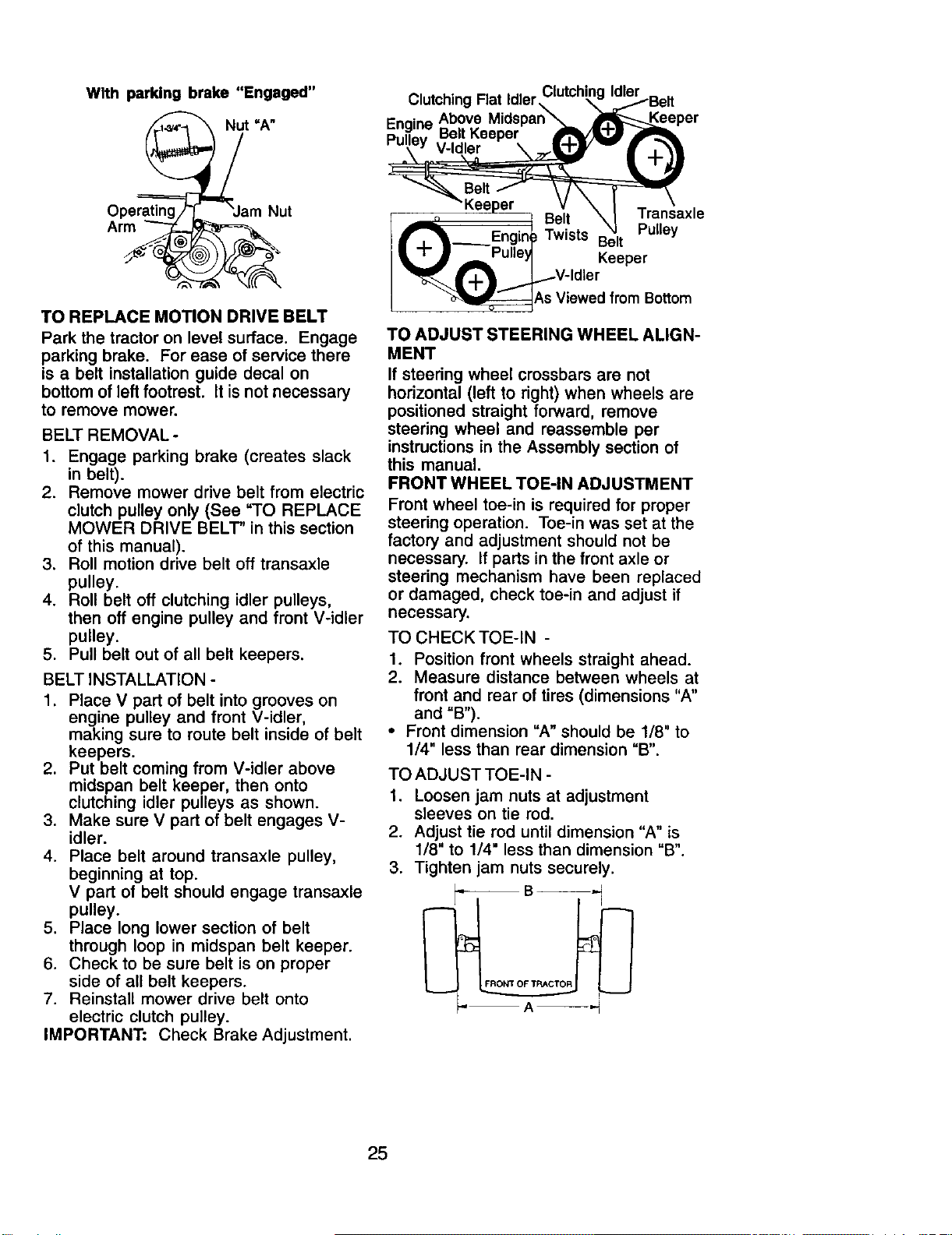
TO ADJUST BRAKE
Your tractor is equipped with an adjustable
brake system which is mounted on the left
side of the transaxle.
If tractor requires more than six (6) feet
stopping distance at high speed in highest
gear on a level dry concrete or paved
surface, then brake must be adjusted.
1. Depress clutch/brake pedal and
engage parking brake.
2. Measure distance between brake
operating arm and nut "A" on brake rod.
3. If distance is other than 1-3/4", loosen
jam nut and turn nut "A" until distance
becomes 1-3/4". Retighten jam nut
against nut "A".
4. Road test tractor for proper stopping
distance as stated above. Readjust if
necessary. If stopping distance is still
greater than six (6) feet in highest gear,
further maintenance is necessary.
Contact a Sears or other qualified
service center.
24
With parking
Ope_
brake "Engaged"
TO REPLACE MOTION DRIVE BELT
Park the tractor on level surface. Engage
parking brake. For ease of service there
is a belt installation guide decal on
bottom of left footrest, it is not necessary
to remove mower.
BELT REMOVAL o
1. Engage parking brake (creates slack
in belt).
2. Remove mower drive belt from electric
clutch pulley only (See "TO REPLACE
MOWER DRIVE BELT" in this section
of this manual).
3. Roll motion drive belt off transaxle
pulley.
4. Roll belt off clutching idler pulleys,
then off engine pulley and front V-idler
pulley.
5. Pull belt out of all belt keepers.
BELT INSTALLATION -
1. Place V part of belt into grooves on
engine pulley and front V-idler,
making sure to route belt inside of belt
keepers.
2. Put belt coming from V-idler above
midspan belt keeper, then onto
clutching idler pulleys as shown.
3. Make sure V part of belt engages V-
idler.
4. Place belt around transaxle pulley,
beginning at top.
V part of belt should engage transaxle
pulley.
5. Place long lower section of belt
through loop in midspan belt keeper.
6. Check to be sure belt is on proper
side of all belt keepers.
7. Reinstall mower drive belt onto
electric clutch pulley.
IMPORTANT: Check Brake Adjustment.
Clutching Rat Idler
Engine Belt Keeper
Belt Transaxle
Pulley
Twists Belt
Keeper
As Viewed from Bottom
TO ADJUST STEERING WHEEL ALIGN-
MENT
If steering wheel crossbars are not
horizontal (left to right) when wheels are
positioned straight forward, remove
steering wheel and reassemble per
instructions in the Assembly section of
this manual.
FRONT WHEEL TOE-IN ADJUSTMENT
Front wheel toe-in is required for proper
steering operation. Toe-in was set at the
factory and adjustment should not be
necessary. If parts in the front axle or
steering mechanism have been replaced
or damaged, check toe-in and adjust if
necessary.
TO CHECK TOE-IN -
1. Position front wheels straight ahead.
2. Measure distance between wheels at
front and rear of tires (dimensions "A"
and "B").
• Front dimension "A" should be 1/8" to
1/4" less than rear dimension "B".
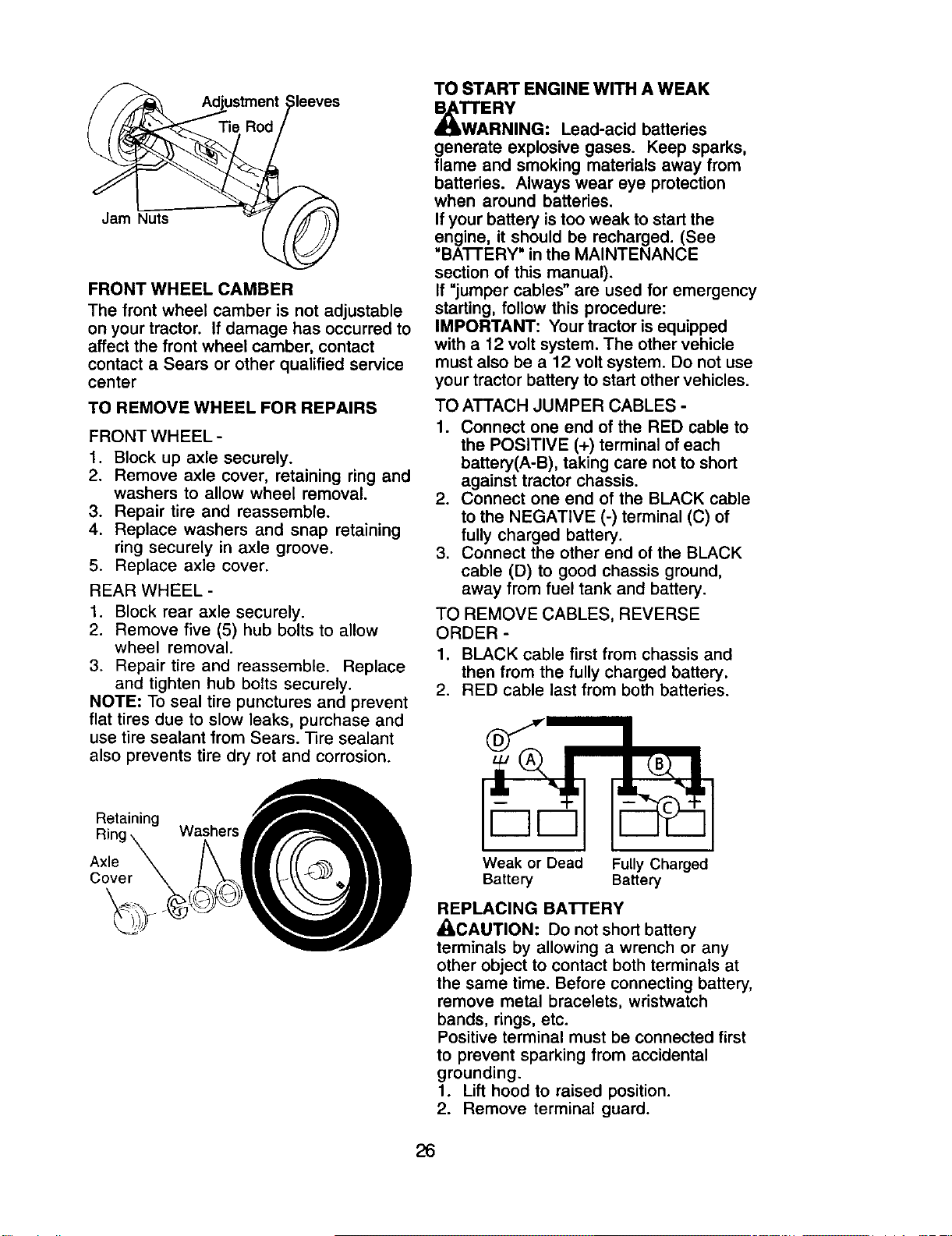
TO ADJUST TOE-IN -
1. Loosen jam nuts at adjustment
sleeves on tie rod.
2. Adjust tie rod until dimension "A" is
1/8" to 1/4" less than dimension "B".
3. Tighten jam nuts securely.
25
ustment
Jam Nuts
FRONT WHEEL CAMBER
The front wheel camber is not adjustable
on your tractor. If damage has occurred to
affect the front wheel camber, contact
contact a Sears or other qualified service
center
TO REMOVE WHEEL FOR REPAIRS
FRONT WHEEL-
1. Block up axle securely.
2. Remove axle cover, retaining ring and
washers to allow wheel removal.
3. Repair tire and reassemble.
4. Replace washers and snap retaining
ring securely in axle groove.
5. Replace axle cover.
REAR WHEEL-
1. Block rear axle securely.
2. Remove five (5) hub bolts to allow
wheel removal.
3. Repair tire and reassemble. Replace
and tighten hub bolts securely.
NOTE: To seal tire punctures and prevent
flat tires due to slow leaks, purchase and
use tire sealant from Sears. Tire sealant
also prevents tire dry rot and corrosion.
Retaining
Ring Washers
Axle
Cover
TO START ENGINE WITH A WEAK
_W'_A ERY
RNING: Lead-acid batteries
generate explosive gases. Keep sparks,
flame and smoking materials away from
batteries. Always wear eye protection
when around batteries.
If your battery is too weak to start the
engine, it should be recharged. (See
=BA'I-rERY" in the MAINTENANCE
section of this manual).
If =jumper cables" are used for emergency
starting, follow this procedure:
IMPORTANT: Your tractor is equipped
with a 12 volt system. The other vehicle
must also be a 12 volt system. Do not use
your tractor battery to start other vehicles.
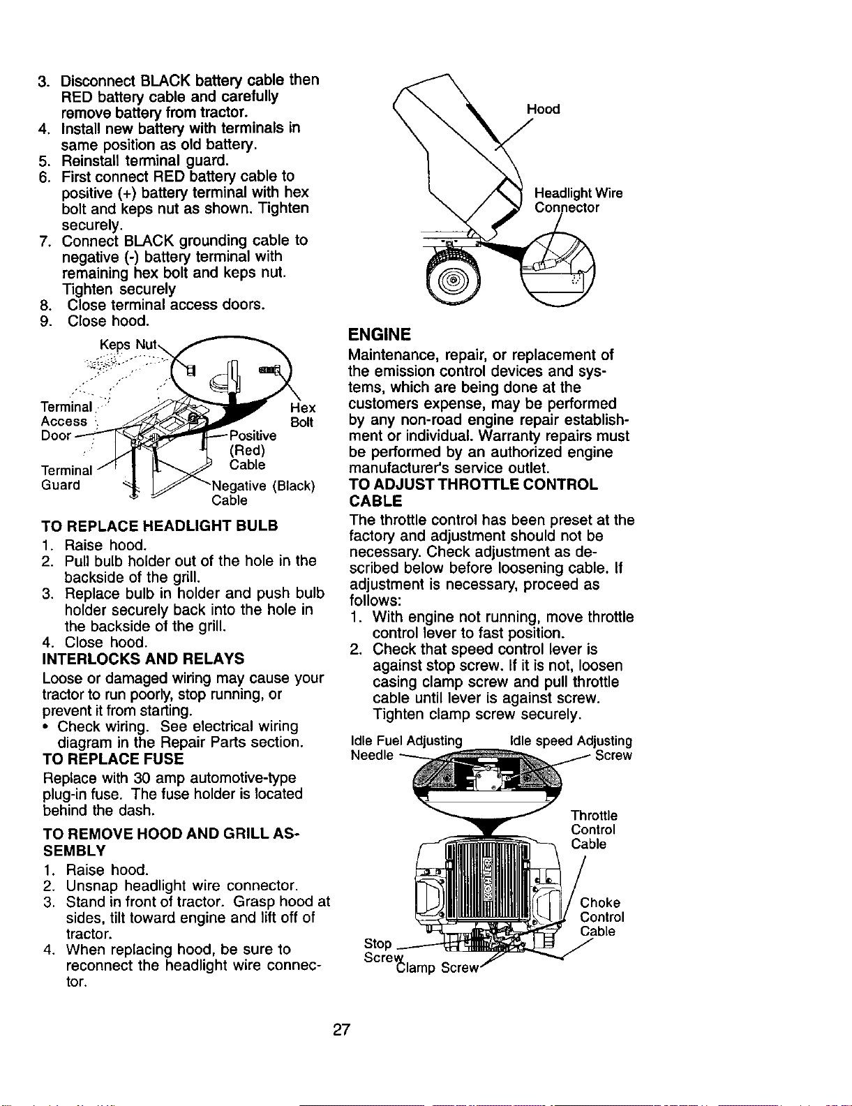
TO ATTACH JUMPER CABLES -
1. Connect one end of the RED cable to
the POSITIVE (+) terminal of each
battery(A-B), taking care not to short
against tractor chassis.
2. Connect one end of the BLACK cable
to the NEGATIVE (-) terminal (C) of
fully charged battery.
3. Connect the other end of the BLACK
cable (D) to good chassis ground,
away from fuel tank and battery.
TO REMOVE CABLES, REVERSE
ORDER -
1. BLACK cable first from chassis and
then from the fully charged battery.
2. RED cable last from both batteries.
Weak or Dead Fully Charged
Battery Battery
REPLACING BATTERY
_CAUTION: Do not short battery
terminals by allowing a wrench or any
other object to contact both terminals at
the same time. Before connecting battery,
remove metal bracelets, wristwatch
bands, rings, etc.
Positive terminal must be connected first
to prevent sparking from accidental
grounding.
1. Lift hood to raised position.
2. Remove terminal guard.
26
3. Disconnect BLACK battery cable then
RED battery cable and carefully
remove battery from tractor.
4. Install new battery with terminals in
same position as old battery.
5. Reinstall terminal guard.
6. First connect RED battery cable to
positive (+) battery terminal with hex
bolt and keps nut as shown. Tighten
securely.
7. Connect BLACK grounding cable to
negative (-) battery terminal with
remaining hex bolt and keps nut.
Tighten securely
8. Close terminal access doors.
9. Close hood.
Keps Nut_
Terminal ::_' :_ _ I_ex
Access- _ _: _ .... Bolt
Door_ _" _----Positive
Terminal / r | _ _ Cable
Guard _ _ "NaegaetiVe(Black)
TO REPLACE HEADLIGHT BULB
1. Raise hood.
2. Pull bulb holder out of the hole in the
backside of the grill.
3. Replace bulb in holder and push bulb
holder securely back into the hole in
the backside of the grill.
4. Close hood.
INTERLOCKS AND RELAYS
Loose or damaged wiring may cause your
tractor to run poorly, stop running, or
prevent it from starting.
• Check wiring. See electrical wiring
diagram in the Repair Parts section.
TO REPLACE FUSE
Replace with 30 amp automotive-type
plug-in fuse. The fuse holder is located
behind the dash.
TO REMOVE HOOD AND GRILL AS-
SEMBLY
1. Raise hood.
2. Unsnap headlight wire connector.
3. Stand in front of tractor. Grasp hood at
sides, tilt toward engine and lift off of
tractor.
4. When replacing hood, be sure to
reconnect the headlight wire connec-
tor.
Hood
Headlight Wire
3ector
ENGINE
Maintenance, repair, or replacement of
the emission control devices and sys-
tems, which are being done at the
customers expense, may be performed
by any non-road engine repair establish-
ment or individual. Warranty repairs must
be performed by an authorized engine
manufacturer's service outlet.
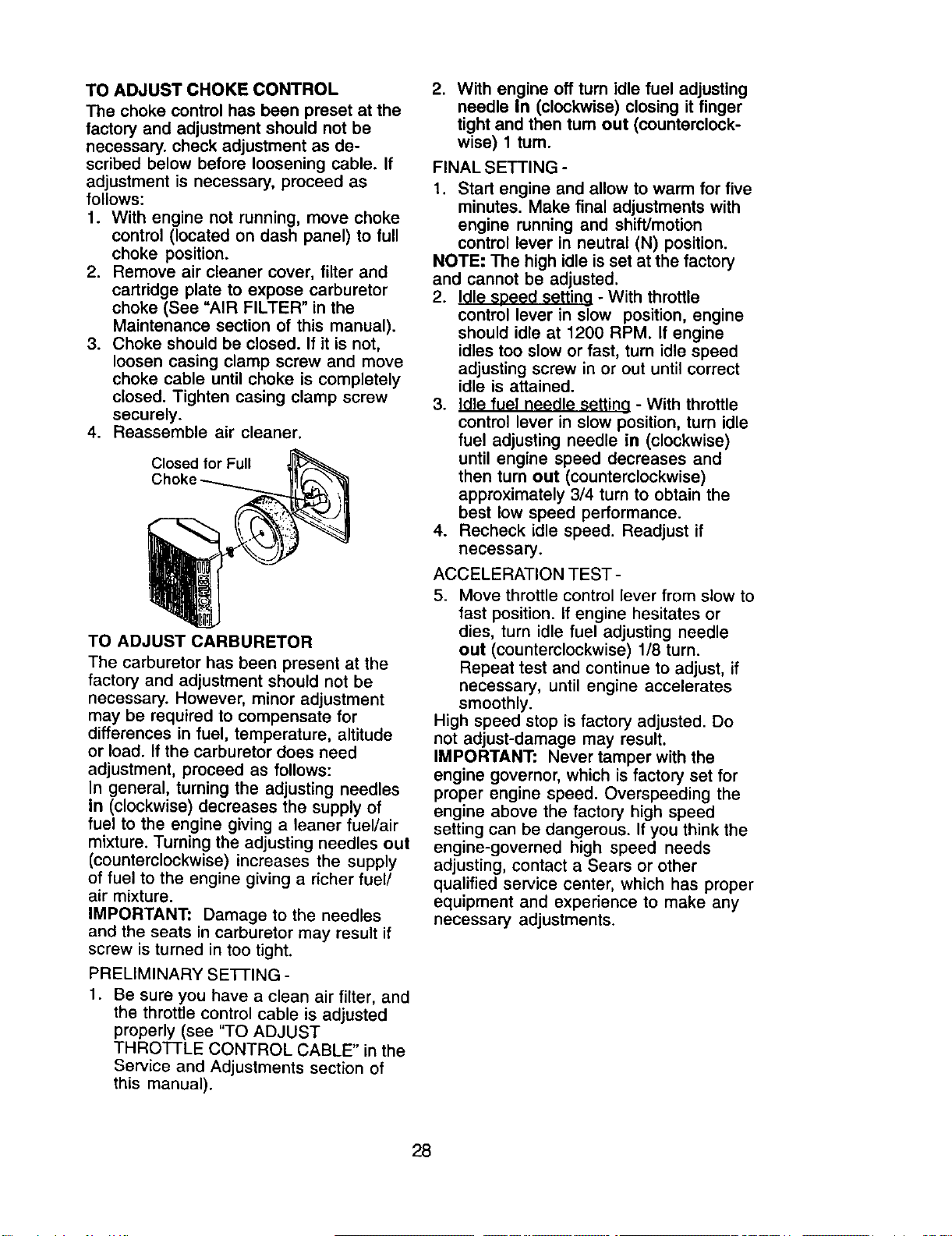
TO ADJUST THRO'n'LE CONTROL
CABLE
The throttle control has been preset at the
factory and adjustment should not be
necessary. Check adjustment as de-
scribed below before loosening cable. If
adjustment is necessary, proceed as
follows:
1. With engine not running, move throttle
control lever to fast position.
2. Check that speed control lever is
against stop screw. If it is not, loosen
casing clamp screw and pull throttle
cable until lever is against screw.
Tighten clamp screw securely.
Idle Fuel Adjusting
Needle
Idle speed Adjusting
Screw
Throttle
Control
Cable
Stol
ScreV_lamI
Choke
Control
Cable
27
TO ADJUST CHOKE CONTROL
The choke control has been preset at the
factory and adjustment should not be
necessary, check adjustment as de-
scribed below before loosening cable. If
adjustment is necessary, proceed as
follows:
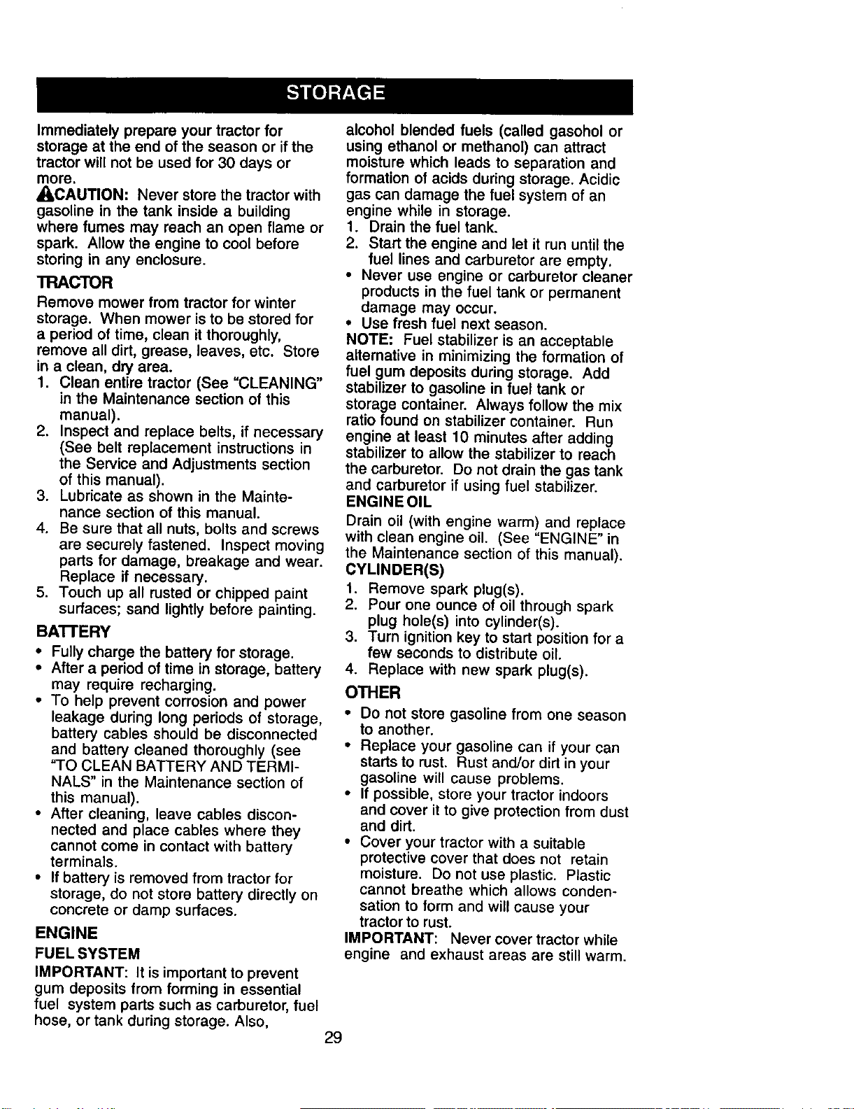
1. With engine not running, move choke
control (located on dash panel) to full
choke position.
2. Remove air cleaner cover, filter and
cartridge plate to expose carburetor
choke (See "AIR FILTER" in the
Maintenance section of this manual).
3. Choke should be closed. If it is not,
loosen casing clamp screw and move
choke cable until choke is completely
closed. Tighten casing clamp screw
securely.
4. Reassemble air cleaner.
Closed for Full
TO ADJUST CARBURETOR
The carburetor has been present at the
factory and adjustment should not be
necessary. However, minor adjustment
may be required to compensate for
differences in fuel, temperature, altitude
or load. If the carburetor does need
adjustment, proceed as follows:
In general, turning the adjusting needles
in (clockwise) decreases the supply of
fuel to the engine giving a leaner fuel/air
mixture. Turning the adjusting needles out
(counterclockwise) increases the supply
of fuel to the engine giving a richer fuel/
air mixture.
IMPORTANT: Damage to the needles
and the seats in carburetor may result if
screw is turned in too tight.
PRELIMINARY SEI-IING -
1. Be sure you have a clean air filter, and
the throttle control cable is adjusted
properly (see "TO ADJUST
THROTTLE CONTROL CABLE" in the
Service and Adjustments section of
this manual).
2. With engine off turn idle fuel adjusting
needle In (clockwise) closing it finger
tight and then turn out (counterclock-
wise) 1 turn.
FINAL SETTING -
1. Start engine and allow to warm for five
minutes. Make final adjustments with
engine running and shift/motion
control lever in neutral (N) position.
NOTE: The high idle is set at the factory
and cannot be adjusted.
2. Idle speed setting - With throttle
control lever in slow position, engine
should idle at 1200 RPM. If engine
idles too slow or fast, turn idle speed
adjusting screw in or out until correct
idle is attained.
3. Idle fuel needle _tting - With throttle
control lever in slow position, turn idle
fuel adjusting needle in (clockwise)
until engine speed decreases and
then turn out (counterclockwise)
approximately 3/4 turn to obtain the
best low speed performance.
4. Recheck idle speed. Readjust if
necessary.
ACCELERATION TEST-
5. Move throttle control lever from slow to
fast position. If engine hesitates or
dies, turn idle fuel adjusting needle
out (counterclockwise) 1/8 turn.
Repeat test and continue to adjust, if
necessary, until engine accelerates
smoothly.
High speed stop is factory adjusted. Do
not adjust-damage may result.
IMPORTANT: Never tamper with the
engine governor, which is factory set for
proper engine speed. Overspeeding the
engine above the factory high speed
setting can be dangerous. If you think the
engine-governed high speed needs
adjusting, contact a Sears or other
qualified service center, which has proper
equipment and experience to make any
necessary adjustments.
28
Immediately prepare your tractor for
storage at the end of the season or if the
tractor wilt not be used for 30 days or
more,
_I_CAUTION: Never store the tractor with
gasoline in the tank inside a building
where fumes may reach an open flame or
spark. AI)ow the engine to coot before
storing in any enclosure.
TRACTOR
Remove mower from tractor for winter
storage. When mower is to be stored for
a period of time, clean it thoroughly,
remove all dirt, grease, leaves, etc. Store
in a clean, dry area.
1. Clean entire tractor (See "CLEANING"
in the Maintenance section of this
manual).
2. Inspect and replace belts, if necessary
(See belt replacement instructions in
the Service and Adjustments section
of this manual).
3. Lubricate as shown in the Mainte-
nance section of this manual.
4. Be sure that all nuts, bolts and screws
are securely fastened. Inspect moving
parts for damage, breakage and wear.
Replace if necessary.
5. Touch up all rusted or chipped paint
surfaces; sand lightly before painting.
BATTERY
• Fully charge the battery for storage.
• After a period of time in storage, battery
may require recharging.
• To help prevent corrosion and power
leakage during long periods of storage,
battery cables should be disconnected
and battery cleaned thoroughly (see
"TO CLEAN BATTERY AND TERMI-
NALS" in the Maintenance section of
this manual).
• After cleaning, leave cables discon-
nected and place cables where they
cannot come in contact with battery
terminals.
• If battery is removed from tractor for
storage, do not store battery directly on
concrete or damp surfaces.
ENGINE
FUEL SYSTEM
IMPORTANT: It is important to prevent
gum deposits from forming in essential
fuel system parts such as carburetor, fuel
hose, or tank during storage. Also,
alcohol blended fuels (called gasohol or
using ethanol or methanol) can attract
moisture which leads to separation and
formation of acids during storage. Acidic
gas can damage the fuel system of an
engine while in storage.
1. Drain the fuel tank.
2. Start the engine and let it run until the
fuel lines and carburetor are empty.
• Never use engine or carburetor cleaner
products in the fuel tank or permanent
damage may occur.
* Use fresh fuel next season.
NOTE; Fuel stabilizer is an acceptable
alternative in minimizing the formation of
fuel gum deposits during storage. Add
stabilizer to gasoline in fuel tank or
storage container. Always follow the mix
ratio found on stabilizer container. Run
engine at least 10 minutes after adding
stabilizer to allow the stabilizer to reach
the carburetor. Do not drain the gas tank
and carburetor if using fuel stabilizer.
ENGINEOIL
Drain oil (with engine warm) and replace
with clean engine oil. (See "ENGINE" in
the Maintenance section of this manual).
CYLINDER(S)
1. Remove spark plug(s).
2. Pour one ounce of oil through spark
plug hole(s) into cylinder(s).
3. Turn ignition key to start position for a
few seconds to distribute oil.
4. Replace with new spark plug(s).
OTHER
• Do not store gasoline from one season
to another.
• Replace your gasoline can if your can
starts to rust. Rust and/or dirt in your
gasoline will cause problems.
• If possible, store your tractor indoors
and cover it to give protection from dust
and dirt.
• Cover your tractor with a suitable
protective cover that does not retain
moisture. Do not use plastic. Plastic
cannot breathe which allows conden-
sation to form and will cause your
tractor to rust.
IMPORTANT: Never cover tractor while
engine and exhaust areas are still warm.
29
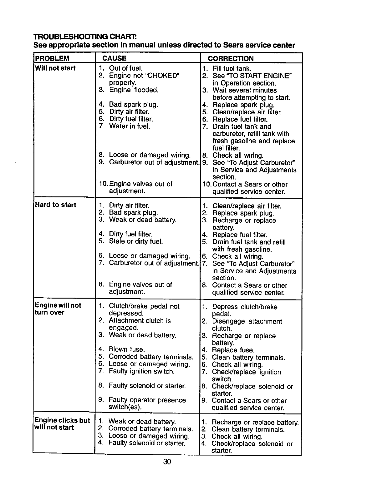
TROUBLESHOOTING CHART:
See appropriate section in manual unless directed to Sears service center
PROBLEM CAUSE CORRECTION
Will not start
Hard to start
Enginewill not
turn over
Engine clicks but
will not start
1. Out of fuel.
2, Engine not "CHOKED"
properly,
3. Engine flooded.
,
5,
6.
7
Bad spark plug. 4.
Dirty air filter. 5.
Dirty fuel filter, 6.
Water in fuel. 7.
8. Loose or damaged wiring.
9. Carburetor out of adjustment.
10. Engine valves out of
adjustment.
1. Dirty air filter.
2. Bad spark plug.
3. Weak or dead battery.
4. Dirty fuel filter.
5. Stale or dirtyfuel.
6. Loose or damaged wiring.
7. Carburetor out of adjustment
8. Engine valves out of
adjustment.
1, Clutch/brake pedal not
depressed.
2, Attachment clutch is
engaged,
3, Weak or dead battery.
14, Blown fuse.
;5, Corroded battery terminals.
:6. Loose or damaged wiring.
7, Faulty ignition switch.
8. Faulty solenoid or starter,
9. Faulty operator presence
switch(es).
1, Fill fuel tank.
2, See "TO START ENGINE"
in Operation section.
3, Wait several minutes
before attempting to start.
Replace spark plug.
Clean/replace air filter.
Replace fuel filter,
Drain fuel tank and
carburetor, refill tank with
fresh gasoline and replace
fuel filter.
8. Check all wiring.
9. See "To Adjust Carburetor"
in Service and Adjustments
section,
10,Contact a Sears or other
qualified service center.
1. Weak or dead battery.
2. Corroded battery terminals.
3. Loose or damaged wiring.
4. Faulty solenoid or starter.
1. Clean/replace air filter.
2. Replace spark plug.
3. Recharge or replace
battery.
4. Replace fuel filter.
5. Drain fuel tank and refill
with fresh gasoline.
6. Check all wiring.
7. See "3-0 Adjust Carburetor"
in Service and Adjustments
section.
8. Contact a Sears or other
qualified service center.
1. Depress clutch/brake
pedal.
2. Disengage attachment
clutch.
3. Recharge or replace
battery.
4. Replace fuse.
5. Clean battery terminals.
6. Check all wiring.
7. Check/replace ignition
switch.
8. Check/replace solenoid or
starter,
9. Contact a Sears or other
qualified service center.
1. Recharge or replace battery.
2. Clean battery terminals.
3. Check all wiring.
4. Check/replace solenoid or
starter.
30
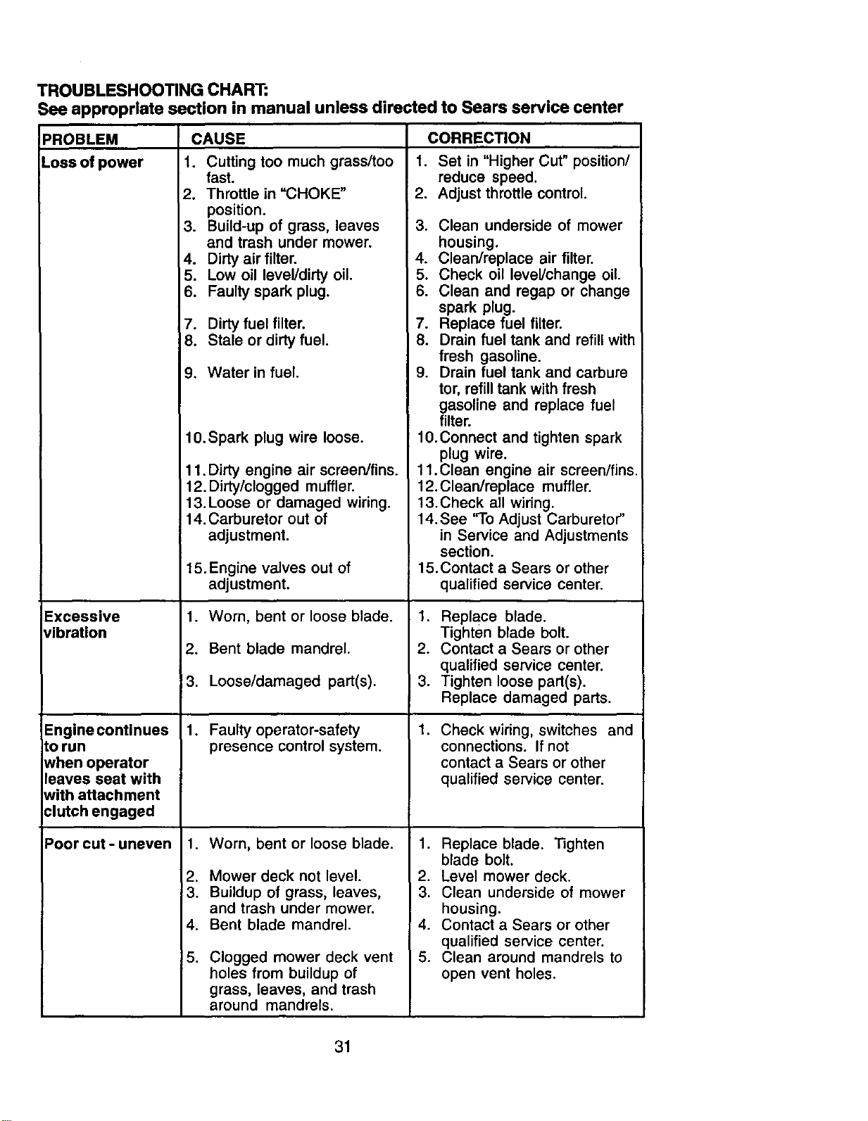
TROUBLESHOOTING CHART:
See appropriate section in manual unless directed to Sears service center
CAUSE
1. Cutting too much grass/too
fast.
2. Throttle in "CHOKE"
position.
3. Build-up of grass, leaves 3.
and trash under mower.
4. Dirty air filter. 4.
5. Low oil level/dirty oil. 5.
6. Faulty spark plug. 6.
7. Dirty fuel filter. 7.
8. Stale or dirty fuel. 8.
9. Water in fuel. 9.
10.Spark plug wire loose.
PROBLEM
LOSS of power
Excessive
vibration
Engine continues
to run
when operator
leaves seat with
with attachment
clutch engaged
Poorcut-uneven
11. Dirty engine air screen/fins.
12. Didy/clogged muffler.
13. Loose or damaged wiring.
14. Carburetor out of
adjustment.
15.Engine valves out of
a_ustment.
1. Worn, bent or loose blade.
2. Bent blade mandrel.
3. Loose/damaged part(s).
1. Faulty operator-safety
presence control system.
.
2.
3.
4.
5.
Worn, bent orloose blade.
Mower deck not level.
Buildup of grass, leaves,
and trash under mower.
Bent blade mandrel.
Clogged mower deck vent
holes from buildup of
grass, leaves, and trash
around mandrels.
CORRECTION
1. Set in "Higher Cut" position/
reduce speed.
2. Adjust throttle control.
Clean underside of mower
housing.
Clean/replace air filter.
Check oil level/change oil.
Clean and regap or change
spark plug.
Replace fuel filter.
Drain fuel tank and refill with
fresh gasoline.
Drain fuel tank and carbure
tor, refill tank with fresh
gasoline and replace fuel
filter.
10.Connect and tighten spark
plug wire.
11.Clean engine air screen/fins.
12.Clean/replace muffler.
13.Check all wiring.
14.See "To Adjust Carburetor"
in Service and Adjustments
section.
15.Contact a Sears or other
qualified service center.
1. Replace blade.
Tighten blade bolt.
2. Contact a Sears or other
qualified service center.
3. Tighten loose part(s).
Replace damaged pads.
,
Check wiring, switches and
connections. If not
contact a Sears or other
qualified service center.
1. Replace blade. Tighten
blade bolt.
2. Level mower deck.
3. Clean underside of mower
housing.
4. Contact a Sears or other
qualified service center.
5. Clean around mandrels to
open vent holes.
31
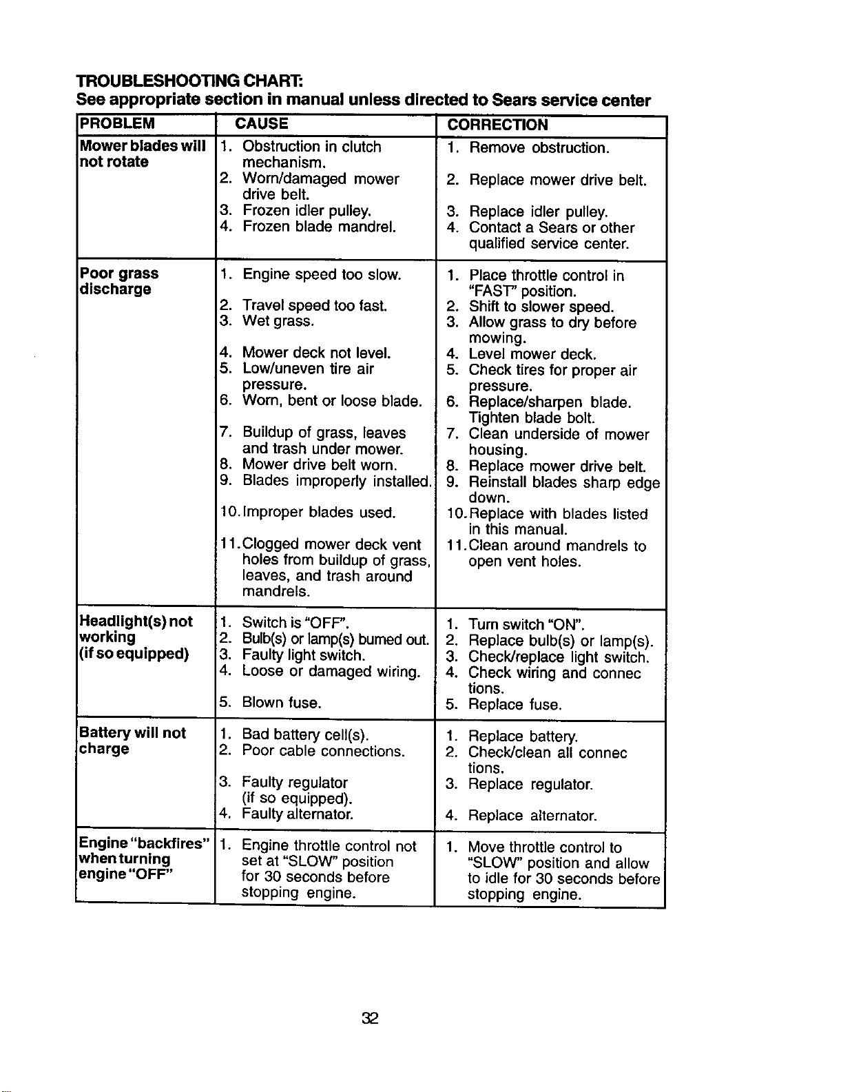
TROUBLESHOOTING CHART:
See appropriate section in manual unless directed to Sears service center
PROBLEM
Mower blades will
not rotate
Poor grass
discharge
CAUSE
1. Obstruction in clutch
mechanism.
2. Worn/damaged mower
drive belt.
3. Frozen idler pulley.
4. Frozen blade mandrel.
1. Engine speed too slow.
2. Travel speed too fast.
3. Wet grass.
4. Mower deck not level.
5. Low/uneven tire air
pressure.
6. Worn, bent or loose blade.
7. Buildup of grass, leaves
and trash under mower.
8. Mower drive belt worn.
9. Blades improperly installed.
10.Improper blades used.
11 .Clogged mower deck vent
holes from buildup of grass,
leaves, and trash around
mandrels.
Headlight(s) not 1.
working 2.
(if so equipped) 3.
4,
5.
Battery will not 1.
charge 2.
3.
4.
1.Engine "backfires"
whenturnlng
engine "OFF"
Switch is "OFF".
Bulb(s) or lamp(s) burned out.
Faulty light switch.
Loose or damaged wiring.
Blown fuse.
Bad battery cell(s).
Poor cable connections.
Faulty regulator
(if so equipped).
Faulty alternator.
Engine throttle control not
set at "SLOW" position
for 30 seconds before
stopping engine.
CORRECTION
1. Remove obstruction.
2. Replace mower drive belt.
3. Replace idler pulley.
4. Contact a Sears or other
qualified service center.
1. Place throttle control in
"FAST" position.
2. Shift to slower speed.
3. Allow grass to dry before
mowing.
4. Level mower deck.
5. Check tires for proper air
pressure.
6. Replace/sharpen blade.
Tighten blade bolt.
7. Clean underside of mower
housing.
8. Replace mower drive belt.
9. Reinstall blades sharp edge
down.
10.Replace with blades listed
in this manual.
11 .Clean around mandrels to
open vent holes.
1. Turn switch "ON".
2. Replace bulb(s) or lamp(s).
3. Check/replace light switch.
4. Check wiring and connec
tions.
5. Replace fuse.
1. Replace battery.
2. Check/clean all connec
tions.
3. Replace regulator.
4. Replace alternator.
.
Move throttle control to
"SLOW" position and allow
to idle for 30 seconds before
stopping engine.
32
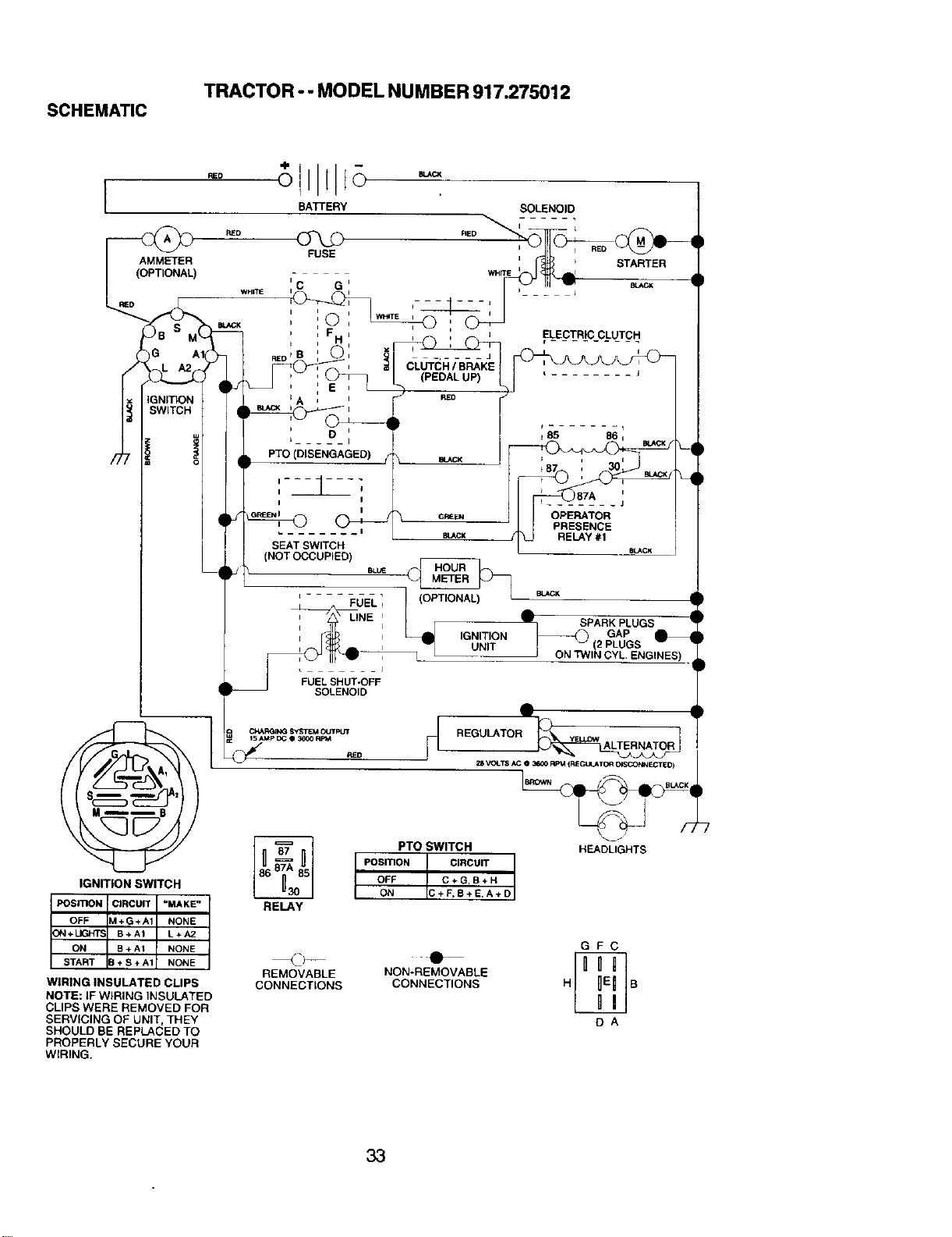
TRACTOR - - MODEL NUMBER 917.275012
SCHEMATIC
BAKERY
SOLENOID
BLAC_
CI4A_ SYSTEM OUTPUT
t5 AMp DC e 3_00 RPM
RELAy
SOLENOID
dlL
HEADLIGHTS
PTO SWITCH
POSI_ON CIRCU_
OFF C+G,B+H
ON C+F,B+E.A÷D
GFC
REMOVABLE NON-REMOVABLE
CONNECTIONS CONNECTIONS H B
DA
IGNITION SWITCH
POSmON : CIRCUIT -MAKE-
OFF M+G+A1 NONE
_N + LK_ B+AI L+A2
ON B+ A1 NONE
START B÷S+A1 NONE
WIRING INSULATED CLIPS
NOTE: IF WIRING INSULATED
CLIPS WERE REMOVED FOR
SERVICING OF UNIT, THEY
SHOULD BE REPLACED TO
PROPERLY SECURE YOUR
WIRING.
33
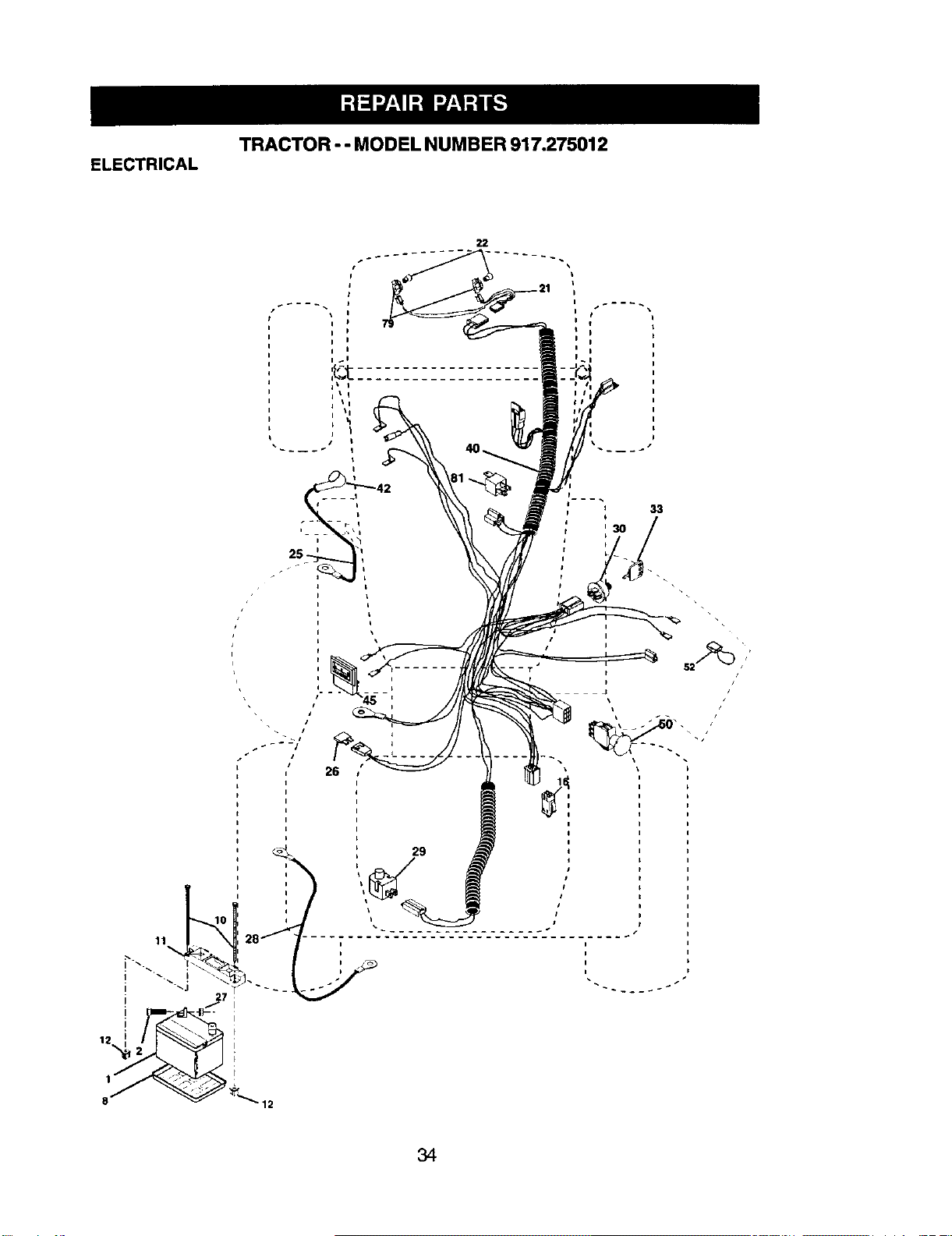
TRACTOR -- MODELNUMBER 917.275012
ELECTRICAL
22
26
29
P •
33
_30
r
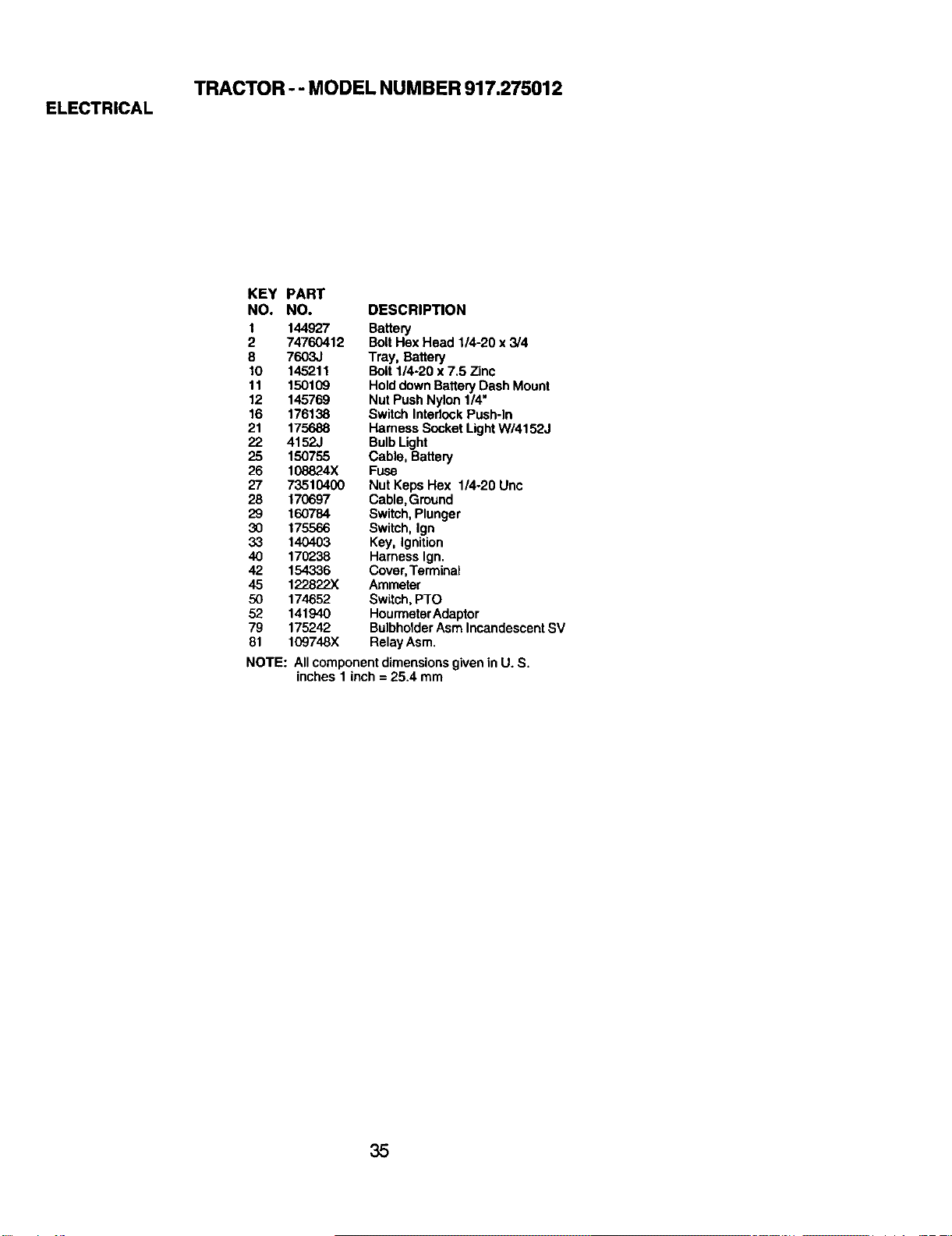
TRACTOR - - MODEL NUMBER 917.275012
ELECTRICAL
KEY PART
NO. NO. DESCRIPTION
1 144927 Battery
2 74760412 BoltHex Head 1/4-20 x3/4
8 7603J Tray, Battery
10 145211 Bolt 1/4-20 x 7,5 Zinc
11 150109 Holddown BatteryDash Mount
12 145769 Nut PushNylon 1/4"
16 176138 Switch Interlock Push-in
21 175688 Harness Socket LightW/4152J
22 4152J BulbLight
25 150755 Cable, Battery
25 108824X Fuse
27 73510400 Nut Keps Hex 1/4-20 Unc
28 170697 Cable, Ground
29 160784 Switch, Plunger
30 175566 Switch, Ign
33 140403 Key, Ignition
40 170238 Harness Ign.
42 154336 Cover,Terminal
45 122822X Ammeter
50 174652 Switch, PTO
52 141940 HourmeterAdaptor
79 175242 BulbholderAsm IncandescentSV
81 109748X RelayAsm.
NOTE: All componentdimensionsgivenin U. S.
inches 1 inch = 25.4 mm
35
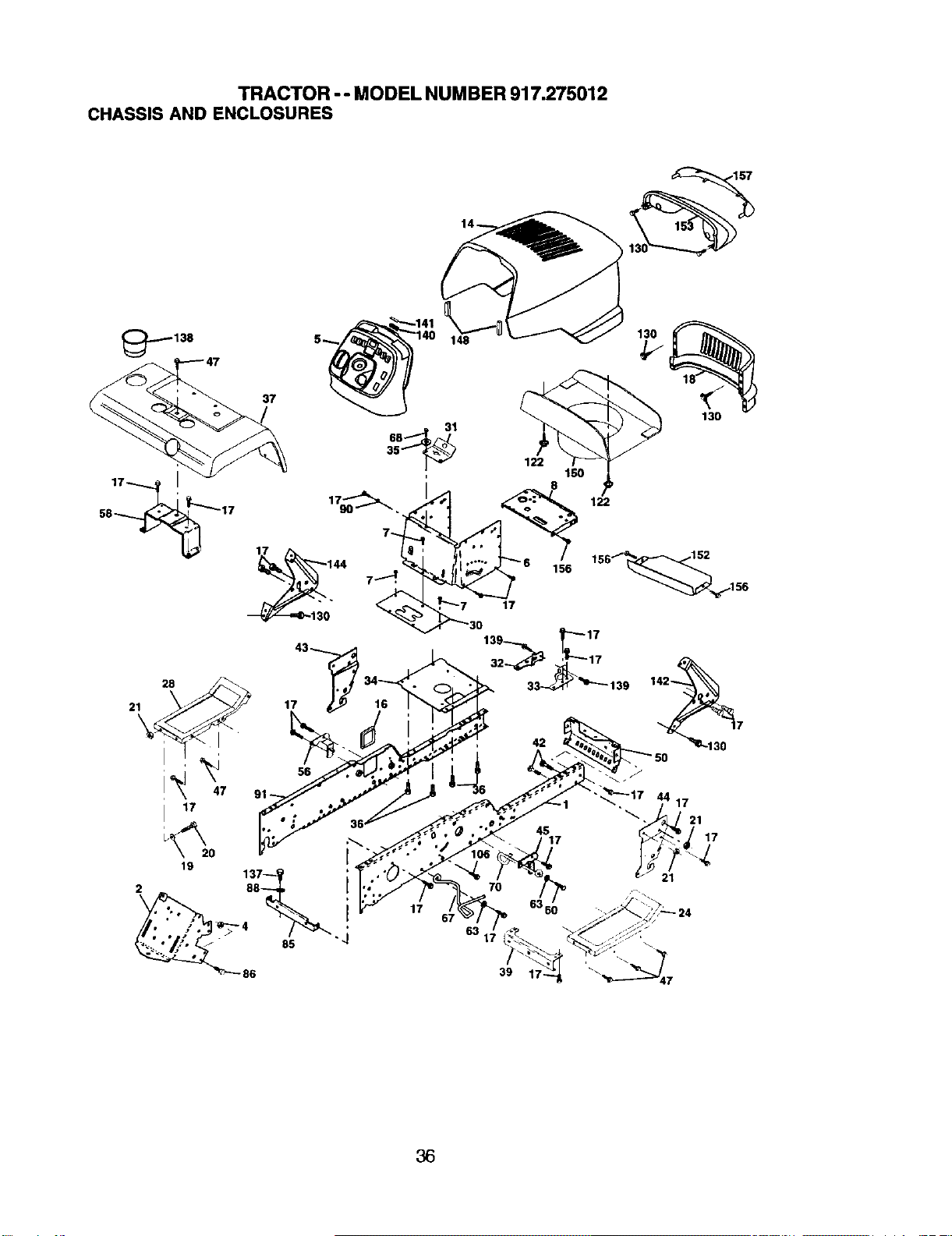
TRACTOR - - MODEL NUM BER 917.275012
CHASSIS AND ENCLOSURES
157
138
37
21 17
i I
47
17
19 0 [
17
17 44 17
1
39
36
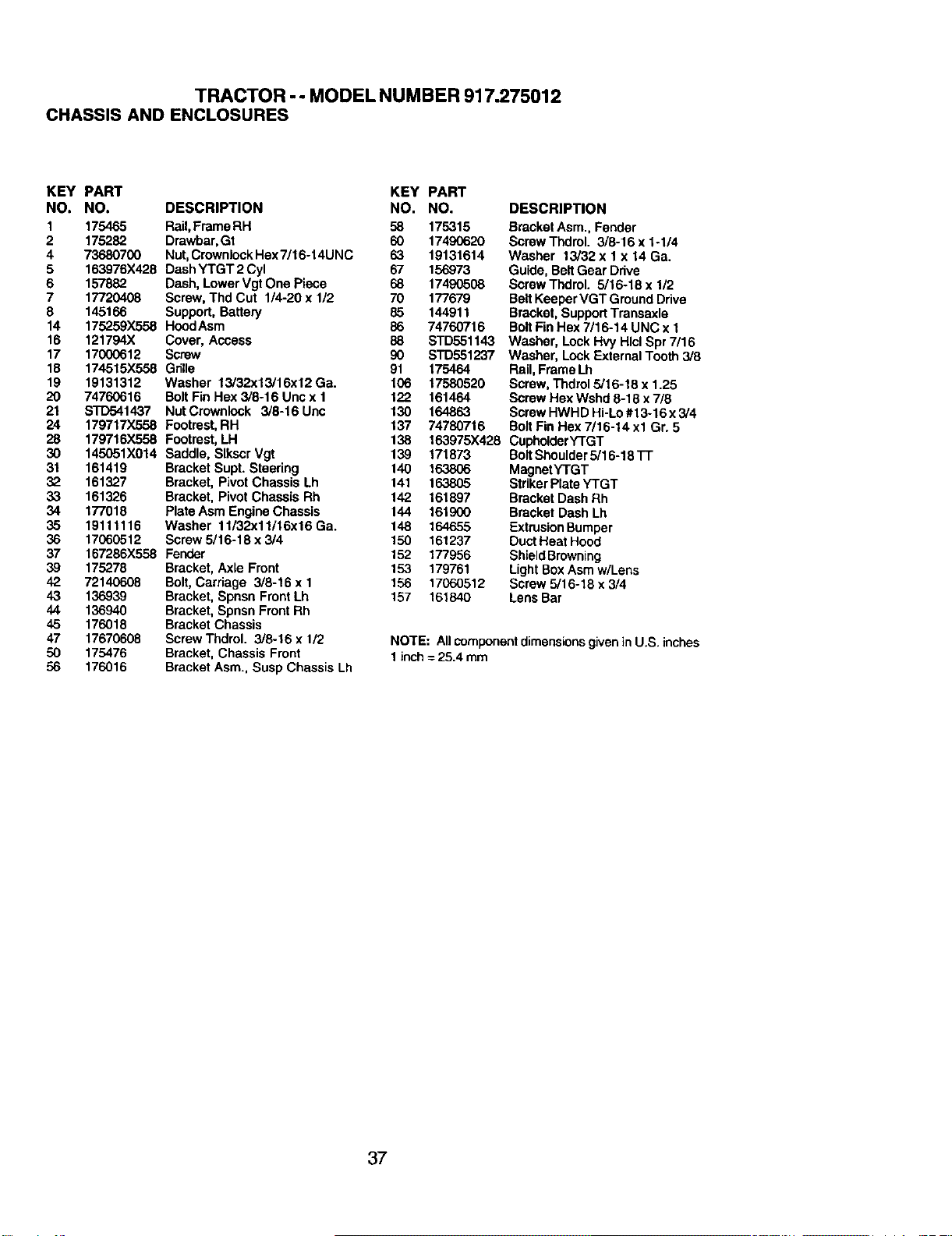
TRACTOR - - MODEL NUMBER 917.275012
CHASSIS AND ENCLOSURES
KEY PART KEY PART
NO. NO. DESCRIPTION NO. NO.
1 175465 Rail,Frame RH 58 175315
2 175282 Drawbar,Gt 60 17490620
4 73680700 Nut,CrownlockHex7/16-14UNC 63 19131614
5 163976X428 DashYTGT 2 Cyl 67 156973
6 157882 Dash, LowerVgt One Piece 68 17490508
7 17720408 Screw,Thd Cut 1/4-20 x 1/2 70 177679
8 145166 Support, Battery 85 144911
14 175259X558 HoodAsm 86 74760716
16 121794X Cover, Access 88
17 17000612 Screw 90
18 174515X558 G6Ue 91
19 19131312 Washer 13/32x13/16x12 Ga. 106
20 74760616 Bolt Fin Hex 3/8-16 Unc x 1 122
21 STD541437 Nut Crownlook 3/8-16 Uac 130
24 179717X558 Footrest,RH 137
28 179716X558 Footrest,LH 138
30 145051X014 Saddle, Slkscr Vgt 139 171873
31 161419 Bracket Supt. Steering 140 163806
32 161327 Bracket, Pivot Chassis Lh 141 163805
33 161326 Bracket, Pivot Chassis Rh 142 161897
34 177018 Plate Asm EngineChassis 144 161900
35 19111116 Washer 11/32x11/16x16Ga. 148 164655
36 17060512 Screw 5/16-18 x 3/4 150 161237
37 167286X558 Fender 152 177956
39 175278 Bracket,Axle Front 153 179761
42 72140608 Bolt,Carriage 3/8-16 x 1 156 17060512
43 136939 Bracket, Spnsn Front Lh 157 161840
44 136940 Bracket,Spnsn Front Rh
45 176018 Bracket Chassis
47 17670608 ScrewThdml. 3/8-16 x 1/2
50 175476 Bracket, Chassis Front
56 176016 Bracket Asm., Susp Chassis Lh
DESCRIPTION
Bracket Asm., Fender
Screw Thdrol. 3/8-16 x 1-1/4
Washer 13/32 x 1 x 14 Ga.
Guide, Belt Gear Drive
Screw Thdrol. 5/16-18 x 1/2
Belt KeeperVGT Ground Drive
Bracket, SupportTransaxle
BoltFin Hex 7/16-14 UNC x 1
STD551143 Washer, LockHvy Hlcl Spr 7/16
S'rD551237 Washer, LockExternal Tooth 3/8
175464 Rail, FrameLh
17580520 Screw, Thdrel 5/16-18 x 1.25
161464 Screw Hex Wshd 8-18 x7/8
164863 Screw HWHD Hi-Lo #13-16 x 3/4
74780716 Bolt Fin Hex 7/16-14 xl Gr. 5
163975X428 CupholderY'rGT
BoltShoulder5/16-18 TT
MagnetYTGT
Striker PlateYTGT
Bracket Dash Rh
Bracket Dash Lh
ExtrusionBumper
DuctHeat Hood
ShieldBrowning
LightBoxAsm w/Lens
Screw 5/16-18 x 3/4
Lens Bar
NOTE: All component dimensions given in U.S. inches
1 inch = 25.4 mm
37
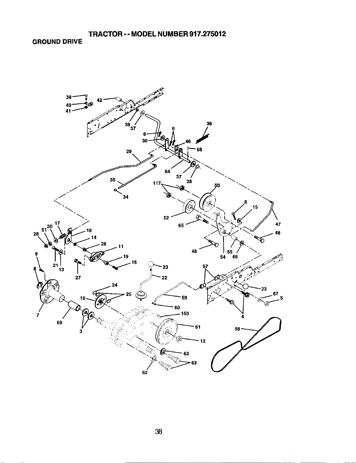
TRACTOR - - MODEL NUMBER 917.275012
GROUND DRIVE
28
\
9
7
15
47
69
62
4
38
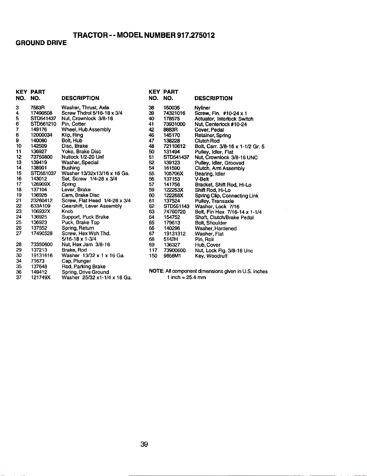
TRACTOR-- MODEL NUMBER917.275012
GROUNDDRIVE
KEY PART KEY PART
NO. NO. DESCRIPTION NO, NO. DESCRIPTION
3 7563R Washer, Thrust, Axle 38 150035
4 17490508 ScrewThdrol 5/16-18 x 3/4 39 74321016
5 STD541437 Nut, Crownlock 3/8-16 40 178575
6 STD561210 Pin, Cotter 41 73931000
7 149176 Wheel, HubAssembly 42 8883R
8 12000034 Klip,Ring 46 145170
9 140080 Bolt,Hub 47 138228
10 142509 Disc, Brake 48 72110612
11 136927 Yoke, Brake Disc 50 131494
12 73750800 Nutlock1/2-20 Unf 51
13 139419 Washer, Special 52
14 138901 Bushing 54
15 STD551037 Washer 13/32x13/16 x 16 Ga. 55
16 143012 Set, Screw 1/4-28 x 3/4 56
17 126909X Spring 57
18 137104 Lever, Brake 59
19 136926 Cam, Brake Disc 60
21 23260412 Screw, Flat Head 1/4-28 x 3/4 61
22 633A109 Gearshift, Lever Assembly 62
23 106932X Knob 63 74760729
24 136925 Support, Puck Brake 64 154752
25 136923 Puck, Brake Top 65 179613
26 137552 Spring, Return 66 140296
27 17490528 Screw, HexWsh Thd. 67 19131312
5/16-18 x 1-3/4 68 5142H
28 73350600 Nut, Hex Jam 3/8-16 69 136327
29 137213 Brake, Rod 117 73900600
30 19131616 Washer 13/32 x 1 x 16 Ga. 150 9858M1
34 71673 Cap, Plunger
35 137648 Rod, Parking Brake
36 149412 Spdng, DriveGround
37 121749X Washer 25/32 x1-1/4 x 16 Ga.
Nyliner
Screw, Fin. #10-24 x 1
Actuator, Interlock Switch
Nut,Centedock #10-24
Cover, Pedal
Retainer,Spdng
ClutchRod
Bolt,Carr. 3/8-16 x 1-1/2 Gr. 5
Pulley, Idler, Flat
S'rD541437 Nut,Crewnlock 3/8-16 UNC
139123 Pulley, Idler, Grooved
161590 Clutch,Arm Assembly
105706X Bearing, Idler
137153 V-Belt
141756 Bracket, ShiftRod, Hi-Lo
122253X ShiftRod, Hi-Lo
1222.68X SpringClip, ConnectingLink
137524 Pulley,Transaxle
STD551143 Washer, Lock 7/16
Bolt, Fin Hex 7/16-14 x 1-1/4
Shaft, Clutch/Brake Pedal
Bolt,Shoulder
Washer, Hardened
Washer, Flat
Pin, Roll
Hub,Cover
Nut, Lock Fig. 3/8-16 Unc
Key, Woodruff
NOTE: All componentdimensionsgivenin U.S. inches
t inch= 25.4 mm
39
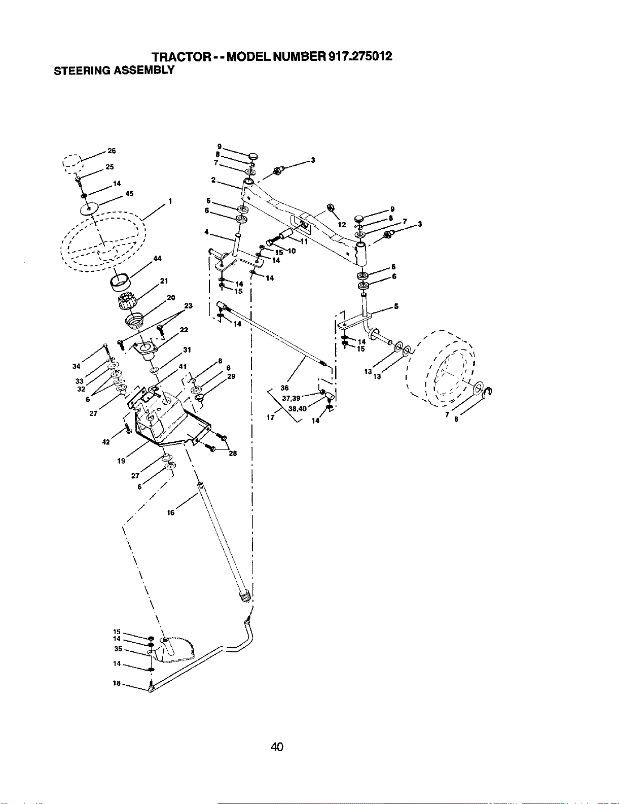
TRACTOR - - MODEL NUMBER 917.275012
STEERINGASSEMBLY
21
20
23
34
32
6
28
19
2,
6'/ / /16
/
\
\
\
\
\
,40 ° /_'
14
1313"
7
8
4O

TRACTOR - -MODELNUMBER917.275012
STEERINGASSEMBLY
KEY PART
NO. NO. DESCRIPTION
1 159944X428
2 178557
3 6855M
4 161849
5 161848
6 6266H
7 121748X
8 12000029
9 121232X
10 74781044
11 136516
12 73901000
13 121749X
14 STD551137
15 S'rD541537
16 145103
17 137347
18 175572
19 156011
20 163887X428
21 159945
22 155105
23 152927
25 STD523710
26 t59946X428
27 3366R
28 17000612
29 104239X
31 138136
32 19111610
33 10040500
34 74780512
35 138059
36 137156
37 7336O600
38 t09850X
39 73700600
40 109651X
41 155246
42 17490508
44 "t60"_35X428
45 19132411
Wheel, Steering
Axle Asm., Front
Fitting,Grease
SpindleAsm, LH
SpindleAsm., RH
Beadng,Race ThrustHarden
Washer 25/32 x 1-5/8 x 16 Ga.
Ring,Klip#T5304-75
Cap, Spindle
Bolt,Fin Hex 5/6-11 x 2-3/4
SpacerBearingAxle Front
Nut, LockFlaP.ge5/6-11 Uric
Washer 25/32 x 1-1/4 x 16 Ga.
Washer, Lock Hvy HlclSpr 3/8
Nut, LockCenter 3/8-24 UNF
Shaft Asm., Steering
RodAsm, Tie BaliJ BallVgt (inc. KeyNo. 36-40)
Dragiink,BaliJoint SolidVgt
SupportAsm., SteeringVgt
Boot,Steering
Adapter, Wheel Steering
Bushing, Strg. BIk
Screw
Bolt,Fin Hex 3/8-16 x 1 Gr. 5
Cap, Wheel Steering
Bearing,Col. Strg.
Screw 3/8-16 x 3/4
Bearing,Flange
Bushing,NylinerSnap
Washer 11/32 x 1 x 10 Ga.
Washer, LockHvy HlclSpr 5/16
Bolt, Hex Hd 5/16-18 x 3/4
Gear, Sector Steering
Tie Rod
Jam NutRH Thread
JointAsm.BallRH Thread
Jam Nut LHThread
Joint Asm. BallLHThread
Bracket Switch InterlockVGT 97
Screw Thdrol 5/16-18 x 1/2 Tyt
Extension, Steering
Washer 13/32 x 1-1/20 x 11 Ga.
NOTE: All component dimensions given in U.S. inches
1 inch = 25.4 mm
41
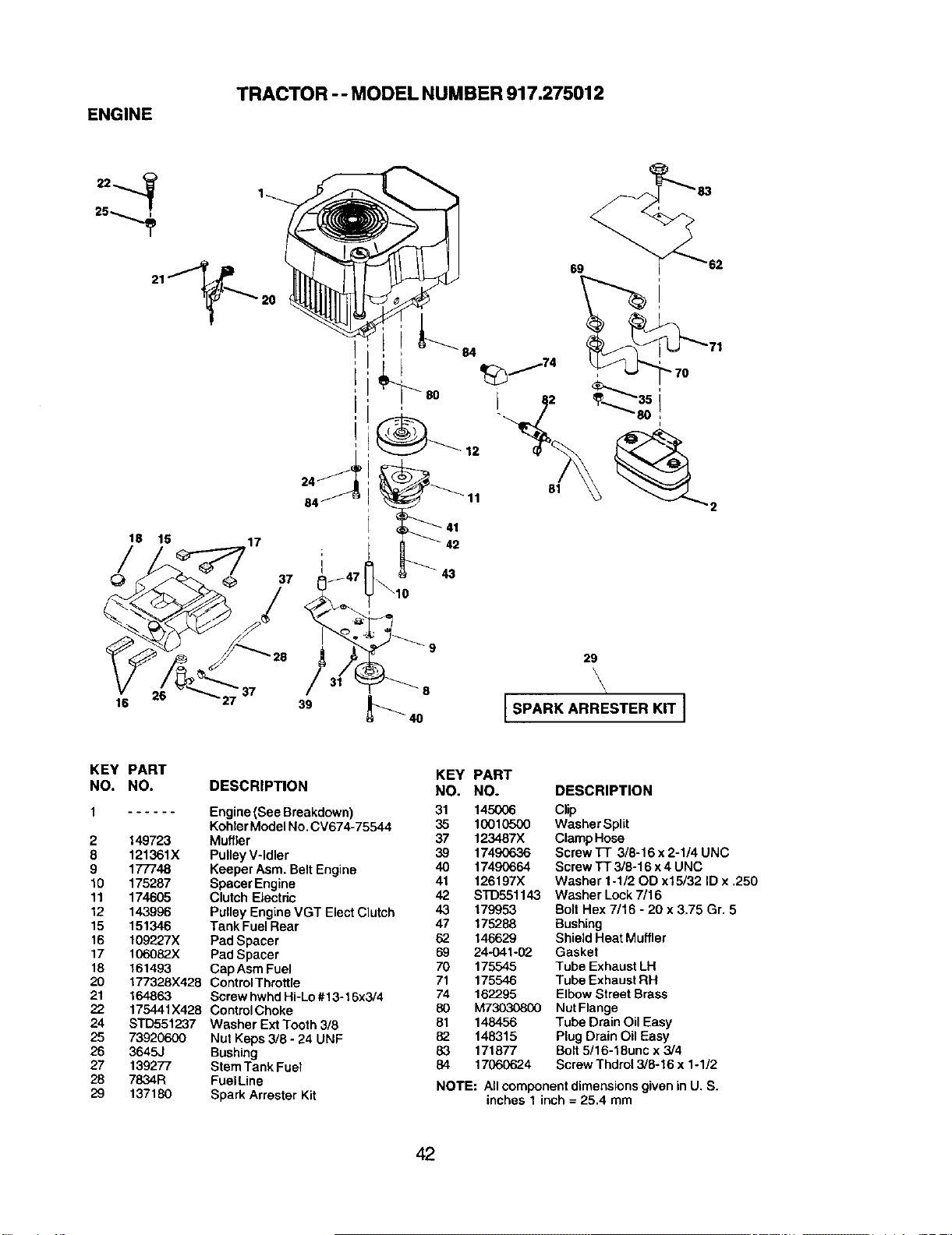
TRACTOR -- MODELNUMBER917.275012
ENGINE
25
217_20
18 15 17
37
84
I
84
t3
69
81
16
26
37
39
8
10
29
\
SPARK ARRESTER KIT ]
KEY PART
NO. NO.
2 149723
8 121361X
9 177748
t0 175287
11 174605
12 143996
15 151346
16 109227X
17 106082_X
18 161493
20 177328X428
21 164863
22 175441X428
24 STD551237
25 73920600
26 3645,.I
27 139277
28 7834R
29 137180
DESCRIPTION
Engine(See Breakdown)
KohterModel No,CV674-75544
Muffler
PulleyV-Idler
Keeper Asm. BeltEngine
Spacer Engine
Clutch Electric
PulleyEngine VGT Elect Clutch
Tank Fuel Rear
PadSpacer
PadSpacer
CapAsm Fuel
ControlThrottle
Screw hwhdHi-Lo#13-16x3/4
Control Choke
Washer ExtTooth 3/8
Nut Keps 3/8 - 24 UNF
Bushing
StemTank Fuel
FuelLine
Spark Arrester Kit
KEY
NO.
31
35
37
39
4O
41
42
43
47
62
69
70
71
74
8O
81
82
83
84
PART
NO. DESCRIPTION
145006 Clip
10010500 Washer Split
123487X ClampHose
17490636 Screw TI- 3/8-16 x 2-1/4 UNC
17490664 Screw TT3/8-16 x4 UNC
126197X Washer 1-1/20D xt5/32 ID x ,250
STD551143 Washer Lock 7/16
179953 Bolt Hex 7/16 - 20 x 3.75 Gr. 5
175288 Bushing
146629 Shield Heat Muffler
24-041-02 Gasket
175545 Tube Exhaust LH
175546 Tube Exhaust RH
162295 Elbow Street Brass
M73030800 Nut Flange
148456 Tube Drain Oil Easy
148315 Plug Drain Oil Easy
171877 Bolt 5/16-18unc x 3/4
17060624 Screw Thdrol 3/8_16 x 1-1/2
NOTE: Allcomponent dimensionsgiven inU. S.
inches 1 inch = 25.4 mm
42
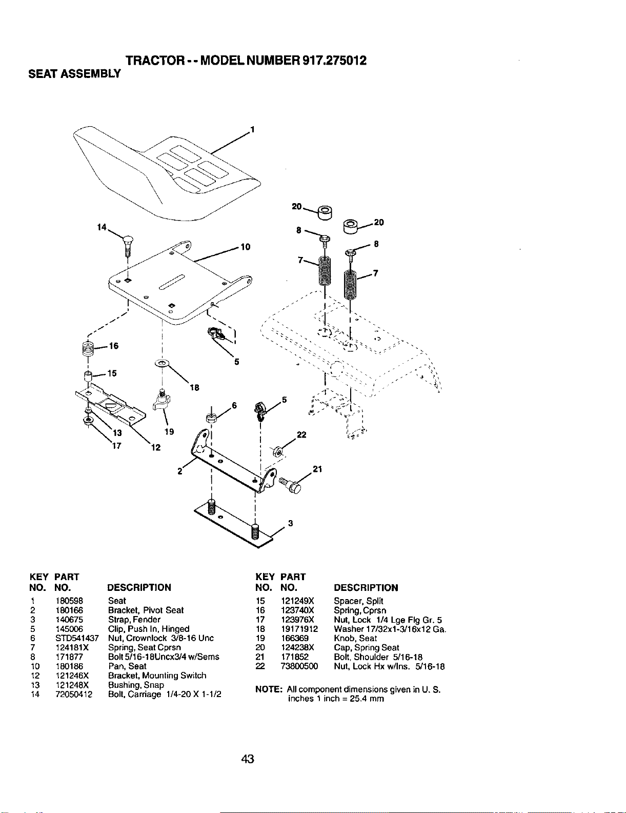
TRACTOR - - MODEL NUMBER 917.275012
SEAT ASSEMBLY
5
21
KEY PART
NO. NO.
1 180598
2 180166
3 140675
5 145006
6 STD541437
7 124181X
8 171877
10 180186
12 121246X
13 121248X
14 72050412
DESCRIPTION
Seat
Bracket, Pivot Seat
Strap,Fender
Clip, Push In, Hinged
Nut, Crownlock 3/8-16 Ucc
Spring,Seat Cpran
Bolt5/16-18Uncx3/4 w/Seres
Pan, Seat
Bracket, Mounting Switch
Bushing,Snap
Bolt,Carriage 1/4-20 X 1-1/2
KEY PART
NO. NO. DESCRIPTION
15 121249X Spacer, Split
16 123740X Spring,Cprsn
17 123976X Nut, Lock 1/4 Lge Fig Gr. 5
18 19171912 Washer 17/32x1-3/16x12 Ga.
19 166369 Knob,Seat
20 124238X Cap, Spring Seat
21 171852 Bolt, Shoulder 5/16-18
22 73800500 Nat, Lock Hx w/Ins. 5/16-18
NOTE: All componentdimensions given in U. S.
inches 1 inch = 25.4 mm
43
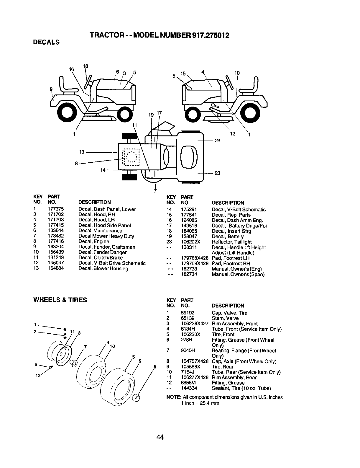
TRACTOR - - MODEL NUMBER 917.275012
DECALS
16
16
6 5
19 17
4
10
13
14--
12
--23
KEY PARr
NO. NO.
1 177375
3 171702
4 171703
5 177415
6 133644
7 178482
9 177416
9 163204
10 156439
11 161249
12 146047
13 164884
DESCRIPTION
Decal, Dash Panel, Lower
Decal, Hood,RH
Decal, Hood, LH
Decal, Hood Side Panel
Decal,Maintenance
Decal Mower Heavy Duty
Deca%,Engine
Decal, Fender,Craftsman
Decal, Fender Danger
Decal, Clutch/Brake
Decal, V-Belt Drive Schematic
Decal, BlowerHousing
7
KEY PART
NO. NO.
14 175291
15 177541
16 164085
17 149516
18 164065
19 138047
23 106202X
- - 138311
- - 179768X428
- - 179769X42B
- - 182733
- - 182734
DESCRIPTION
Decal,V-Belt Schematic
Decal, Repl Parts
Decal, Dash Atom Eng.
Decal, BatteryDnge/Poi
Decal, Insert Strg
Decal, Battery
Reflector,Taillight
Decal, Handle Lft Height
Adjust (Uft Handle)
Pad, Footrest LH
Pad, FootrestRH
Manual,Owner's (Eng)
Manual,Owner's(Span)
WHEELS & TIRES
3
4
10
KEY PART
NO. NO.
1 59192
2 65139
3 106228X427
4 6134H
5 106230X
6 278H
7 9040H
8 104757X428
9 105588X
10 7154J
11 106277X428
12 6856M
-- 144334
DESCRIPTION
Cap, Valve, Tire
Stem, Valve
Rim Assembly,Front
Tube, Front (Servk_eItem Only)
Tire, Front
Fitting,Grease (FrontWheel
Only)
Bearing, F|ange(F_ontWheel
on=y)
Cap, Axle (Front Wheel Only)
Tire, Rear
Tube, Rear (Service ttem Onty)
Rim Assembly, Rear
Fitting, Grease
Sealant, Tire (10 oz. Tube)
NOTE: Allcomponentdimensionsgiven in U.S. inches
1 inch= 25.4 mm
44
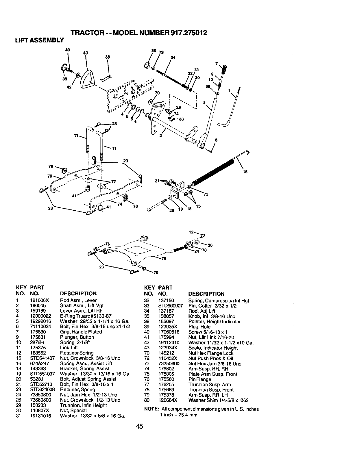
TRACTOR - - MODEL NUMBER 917.275012
LIFTASSEMBLY
19 18
15
16
12
75
KEY PART
NO. NO.
1 121(X)6X
2 180045
3 159189
4 12000022
5 19292016
6 71110624
7 175830
9 175831
10 2876H
11 175375
12 163552
15 STD541437
16 674A247
18 143363
19 STD551037
20 5328J
21 S'T'[To2710
23 STD624008
24 73350800
26 73680800
29 150233
30 110807X
31 19131016
KEY PART
DESCRIPTION NO. NO.
Rod Asm., Lever 32 137150
Shaft Asm., Lift Vgt 33 STD560907
Lever Asm., Lift Rh 34 137167
E-RingTruarc#5133-87 35 138057
Washer 29/32 x 1-1/4 x 16 Ga. 38 155097
Bolt,Fin Hex 3/8-16 unc x1-1/2 39 123935X
Grip,Handle Fluted 40 17060516
Plunger, Button 41 175994
Spring 2-1/8" 42 19112410
Link Lift 43 123934X
RetainerSpring 70 145212
Nut, Crewnlock 3/8-16 Unc 72 110452X
Spring Asm., Assist Lift 73 73350600
Bracket, Spring Assist 74 175802
Washer 13/32 x 13/16 x 16 Ga. 75 175805
Bolt,Adjust Spring Assist 76 175560
Bolt, Fin Hex 3/8-16 x 1 77 176205
Retainer, Spring 78 175689
Nut, Jam Hex 1/2-13 Unc 79 175378
Nut, Crownlock 1/2-13 Unc 80 126684X
Trunnion, InfinHeight
Nut, Special
Washer 13/32 x 5/8 x 16 Ga.
DESCRIPTION
Spring,CompressionInfHgt
Pin, Cotter 3/32 x 112
Rod, Adj Lift
Knob. laf 3/8-16 Unc
Pointer,Height Indicator
Plug,Hole
Screw 5/16-18 x 1
Nut. Lift Link 7/16-20
Washer 11/32 x 1-1/2 xl0 Ga.
Scale. IndicatorHeight
Nut Hex Flange Lock
Nut PushPhos& Oil
Nut Hex Jam 3/8-16 Unc
Arm Susp.RR. RH
Plate Asm Susp. Front
PinFlange
TrunnionSusp.Arm
TrunnionSusp.Front
ArmSusp. RR. LH
Washer Sh_m1/4-5/8 x .062
NOTE: All component dimensions given in U.S. inches
1 inch = 25.4 mm
45
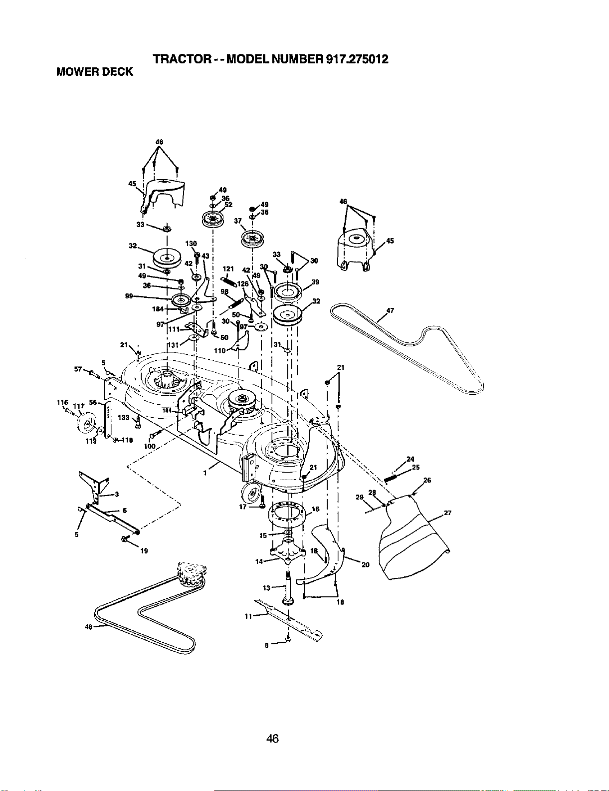
TRACTOR - - MODEL NUMBER 917.275012
MOWER DECK
46
I
130
49
I
46
i I ii
116
11!
19
1
17
26
46
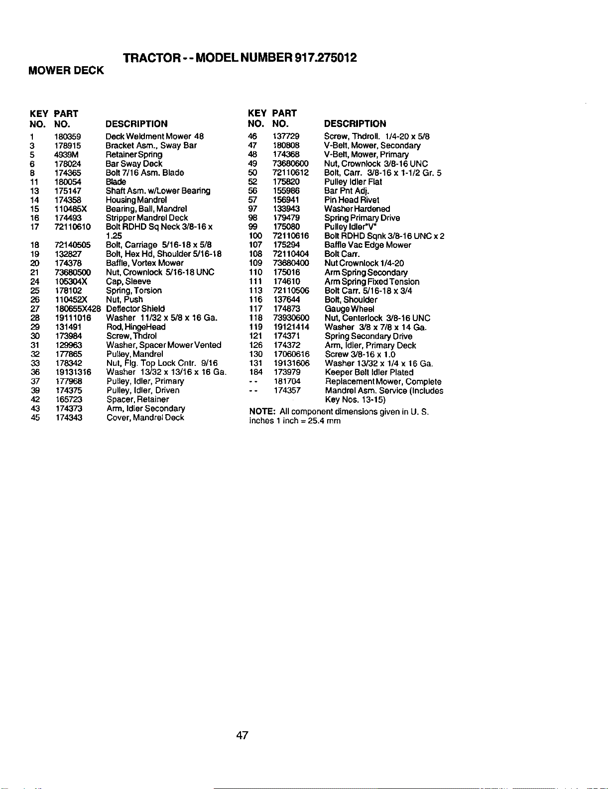
TRACTOR - - MODEL NUMBER 917.275012
MOWER DECK
KEY PART
NO. NO. DESCRIPTION
1 180359 DeckWeldment Mower 48 46 137729
3 178915 BracketAsm., Sway Bar 47 180808
5 49_9M RetainerSpring 48 174368
6 178024 Bar Sway Deck 49 73680600
8 174365 Bolt7/16 Asm. Blade 50 72110612
11 180054 Blade 52 175820
13 175147 ShaftAsm.w/Lower Bearing 56 155986
14 174358 HousingMandrel 57 156941
15 110485X Bearing,Bali,Mandrel 97 133943
16 174493 StripperMandralDeck 98 179479
17 72110610 BoltRDHD Sq Neck 3/6-16 x 99 175080
1.25 100 72110616
18 72140505 Bolt, Carriage 5/16-18 x5/8 107 175294
19 132827 Bolt,Hex Hd, Shoulder5/16-18 108 72110404
20 174378 Baffle,Vortex Mower 109 73680400
21 73680500 Nut,Crownlock 5/16-18UNC 110 175016
24 105304X Cap, Sleeve 111 174610
25 178102 Spdng,Torsion 113 72110506
26 110452X Nut, Push 116 137644
27 180655X428 DeflectorShield 117 174873
28 19111016 Washer 11/32x5/8x16Ga. 118 73930600
29 131491 Rod,HingeHead 119 19121414
30 173984 Screw,Thdrol 121 174371
31 129963 Washer, SpecerMower Vented 126 174372
32 177865 Pulley,Mandrel 130 17060616
33 178342 Nut, Fig. Top LockCntr. 9/16 131 19131606
36 19131316 Washer 13/32 x 13/16 x 16 Ga. 184 173979
37 177968 Pulley, Idler,Primary - - 181704
39 174375 Pulley, Idler, Driven - - 174357
42 165723 Spacer,Retainer
43 174373 Arm, IdlerSecondary
45 174343 Cover, Mandrel Deck
KEY PART
NO. NO. DESCRIPTION
Screw, Thdroll. 1/4-20 x 5/8
V-Belt, Mower, Secondary
V-Belt, Mower, Primary
Nut, Crownlock 3/8-16 UNC
Bolt, Carr. 3/8-16 x 1-1/2 Gr. 5
Pulley Idler Flat
Bar Pnt Adj.
PinHead Rivet
Washer Hardened
Spdng Pdmary Drive
Pulley Idler'V"
Bolt RDHD Sqnk 3/8-16 UNC x 2
Baffle Vac Edge Mower
BoltCan'.
NutCrownlock1/4-20
ArmSpdngSecondary
ArmSpringFixedTension
BoltCarr. 5/16-18 x 3/4
Bolt,Shoulder
GaugeWheel
Nut,Centerlock 3/8-16 UNC
Washer 3/8 x 718 x 14 Ga.
SpringSecondaryDrive
Arm, Idler,Pdmary Deck
Screw 3/8-16 x 1.0
Washer 13/32 x 1/4 x 16 Ga.
Keeper Belt Idler Plated
Replacement Mower, Complete
Mandrel Asm. Service (Includes
Key Nos. 13-15)
NOTE: All componentdimensions given in U. S.
inches 1 inch= 25.4 mm
47
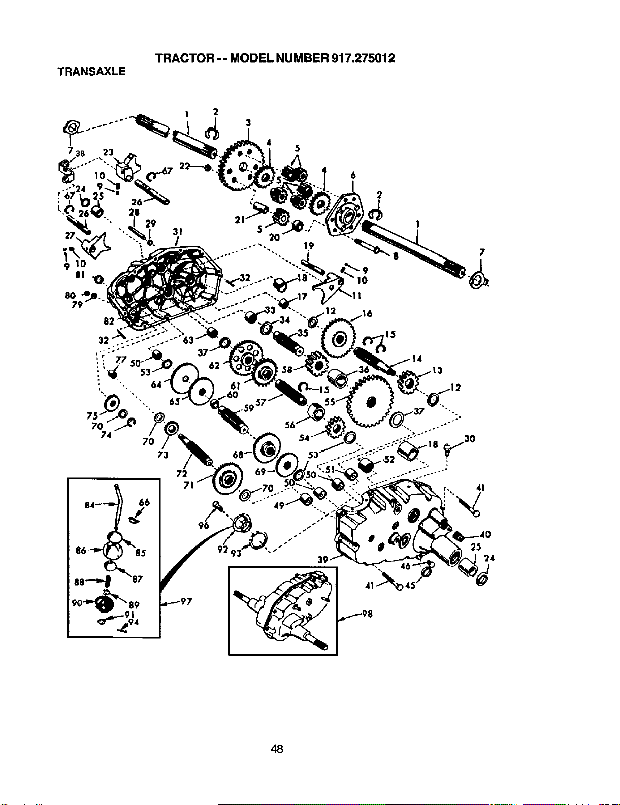
TRACTOR o- MODEL NUMBER 917.275012
TRANSAXLE
48
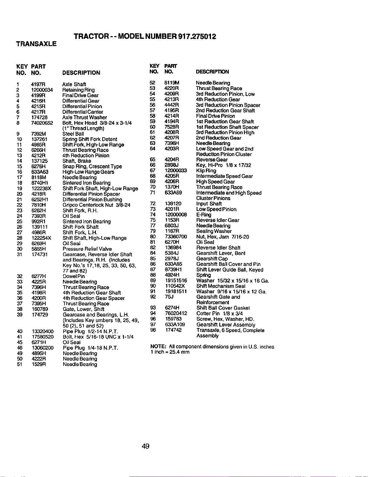
TRANSAXLE
TRACTOR - - MODEL NUMBER 917.275012
KEY PART
NO. NO.
1 4197R
2 12000034
3 4199R
4 4216R
5 4215R
6 4217R
7 174728
8 7402O652
9 7392M
10 137261
11 4985R
12 626614
13 4212R
14 137125
15 6276H
16 633A63
17 6118M
18 6740H1
19 122238X
20 4218R
21 6252H1
99 7_ _-I
&?.62H
24 7393R
25 992R1
26 139111
27 4986R
28 122254X
29 6269H
30 5855H
31 174731
32 6277H
33 4225R
34 7396H
35 4198R
36 4200R
37 7395H
38 160789
39 174729
40 13320400
41 17580520
45 6271H
46 13060200
49 4895H
50 4222R
51 1529R
DESCRIPTION
KEY PART
NO. NO. DESCRIPTION
Axle Shaft 52 8119M
Retaining Ring 53 4220R
FinalDrive Gear 54 4209R
DifferentialGear 55 4213R
DifferentialPinion 56 4442R
Differential Carrier 57 4195R
Axle Thrust Washer 58 4214R
Bolt, Hex Head 3/8-24 x 3-1/4 59 4194R
60 752.8R
(1"Thread Length)
Steel Ball 61 4208R
Spring Shift Fork Detent 62 4207R
63 7398H
ShiftFork, High-Low Range
Thrust Bearing Race 64 4203R
4th ReductionPinion
Shaft, Brake 65 4204R
66 2898J
Snap RiG, Crescent Type 67 12000033
High-LowRange Gears
NeedleBearing 68 4205R
SinteredIron Bearing 69 4206R
Shift Fork Shaft, High-Low Range 70 1370H
DifferentialPinionSpacer 71 633A69
Differential Pinion Bushing 72 139120
GripcoCentedocY.Nut 3/8-24 73 4201R
Shift Fork, R.H.
Oil Seal 74 12000008
Sintered iron Beadng 75 1153R
Shift Fork Shaft 77 6803J
Shift Fork, L.H. 79 1167R
Shift Shaft, High-Low Range 80 73360700
Oil Seal 81 6270H
Pressure ReliefValve 82 136984
Gearcase, Reverse IdlerShaft 84 5384J
85 2978J
and Bearings, R.H. (Includes 86 633A85
Key No.'s 17,18, 25, 33, 50, 63, 87 8739H1
77 and 82)
Dowel Pin 88 4924H
Needle Bearing 89 19151516
ThrustBearingRace 90 110542X
4th Reduction Gear Shaft 91 19181511
4th Reduction Gear Spacer 92 75J
ThrustBearing Race
Gate, Lower, Shift 93 6274H
Gearease and Bearings, L,H. 94 76020412
(Includes Key umbers 18, 25, 49, 96 159783
50 (2), 51 and 52) 97 633A109
Pipe Plug 1/2-14 N.P.T. 98 174742
Bolt,Hex 5/16-18 UNC x 1-1/4
OilSeal
Pipe Plug 1/4-18 N.P.T.
NeedleBearing
Needle Beadng
Needle Bearing
Needle Bearing
Thrust BearingRace
3rd Reduction Pinion,Low
4th Reduction Gear
3rd ReductionPinionSpacer
2nd ReductionGear Shaft
Rnal DrivePinion
1st Reduction Gear Shaft
1stReduction Shaft Spacer
3rd ReductionPinionHtgh
2nd ReductionGear
Needle Bearing
LowSpeed Gear end2nd
ReductionPinionCluster
Reverse Gear
Key, Hi-Pro 1/8x 17132
KlipRing
IntermediateSpeed Gear
HighSpeed Gear
Thrust Bearing Race
IntermediateandHigh Speed
ClusterPinions
Input Shaft
LowSpeed Pinion
E-Ring
Reverse IdlerGear
Needle Bearing
SealingWasher
Nut, Hex, Jam 7/16-20
Oil Seal
Reverse Idler Shaft
Gearshift Lever, Bent
GearshiftCap
Gearshift BallCover and Pin
Shift Lever Guide Ball, Keyed
Spring
Washer 15/32 x 15/16 x 16 Ga.
Shift Mechanism Seal
Washer 9/16 x 15/16 x 12 Ga.
Gearshift Gate and
Reinforcement
ShiftBall Cover Gasket
Cotter Pin 1/8 x 3/4
Screw, Hex, Washer, HD.
Gearshift Lever Assembly
Transaxle,6 Speed, Complete
Assembly
NOTE: All componentdimensionsgiven inU.S. inches
1inch= 25.4 mm
49
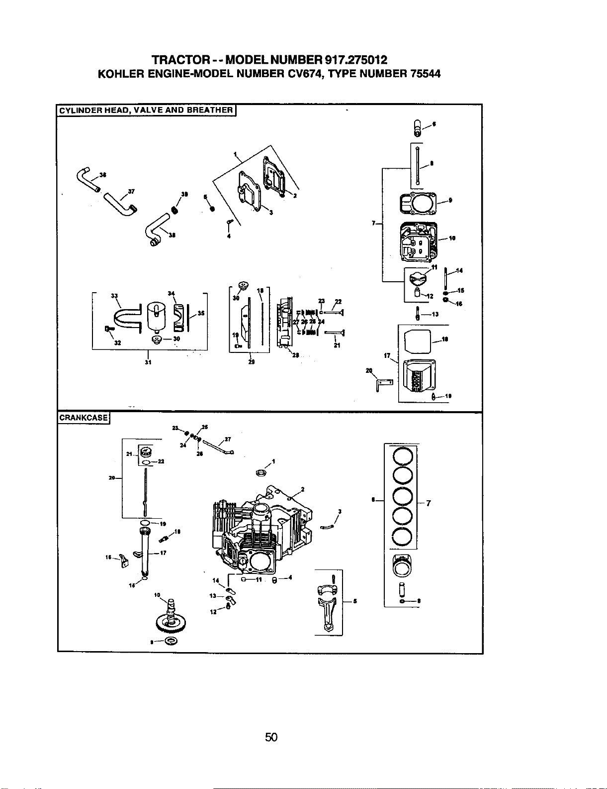
TRACTOR - - MODEL NUMBER 917.275012
KOHLER ENGINE-MODEL NUMBER CV674, TYPE NUMBER 75544
CYLINDER HEAD, VALVE AND BREATHER I
jg
CRANKCASEJ
_,11 1_11t:
3_1 " \28 17
3
/
v I
'- XI-7
v i
v i
0---8
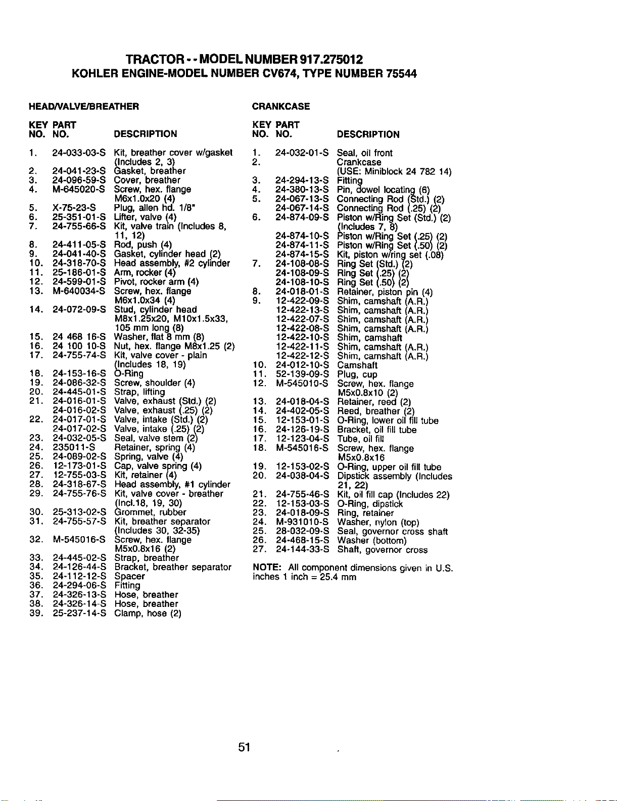
TRACTOR ° - MODEL NUMBER 917.275012
KOHLER ENGINE-MODEL NUMBER CV674, TYPE NUMBER 75544
HEAD/VALVE/BREATHER
CRANKCASE
KEY PART KEY PART
NO. NO. DESCRIPTtON NO. NO. DESCRIPTION
1. 24-033-03-S Kit, breather cover w/gasket 1. 24-032-01-S
(Includes 2, 3) 2.
2. 24-041-23-S Gasket, breather
3. 24-096-59-S Cover, breather 3. 24-294-13-S
4. M-645020-S Screw, hex. flange 4. 24-380-13-S
M6xl.0x20 (4) 5. 24-067-13-S
5. X-75-23-S Plug, allen hd. 1/8" 24-067-14-S
6. 25-351-01-S Lifter, valve 44) 6. 24-874-09-S
7. 24-755-66-S Kit, valve tram (Includes 8,
11, 12) 24-874-10-S
8. 24-411-05-S Rod, push (4) 24-874-11-S
9. 24-041-40-S Gasket, cylinder head (2) 24-874-15-S
10. 24-318-70-S Head assembly, #2 cylinder 7. 24-108-08-S
11. 25-186-01-S Arm, rocker (4) 24-108-09-S
12. 24-599-01-S Pivot, rocker arm (4) 24-108-10-S
13. M-640034-S Screw, hex. flange 8. 24-018-01-S
M6x1.0x34 (4) 9. 12-422-09-S
14. 24-072-09-S Stud, cylinder head 12-422-13-S
M8xt .25x20, M10xl.5x33, 12-422o07-S
105 mm long (8) 12-422-08-S
15. 24 468 16-S Washer, flat 8 mm (8) 12-422-10-S
16. 24 100 10-S Nut, hex. flange M8x1.25 (2) 12-422-11-S
17. 24-755-74-S Kit, valve cover - plain 12-422-12-S
(Includes 18, 19) t0. 24-012-10-S
18. 24-153-16-S O-Ring 11. 52-139-09-S
19. 24-086-32-S Screw, shoulder (4) 12. M-545010-S
20. 24-445-01-S Strap, lifting
21. 24-016-01-S Valve, exhaust (Std.) (2) 13. 24-018-04-S
14. 24-402-05-S
24-016-02-S Valve, exhaust (.25) (2)
22. 24-017-01-S Valve, intake (Std.} (2) 15. 12-153-01-S
24-017-02-S Valve, intake (.25) (2) 16. 24-126-19-S
23. 24-032-05-S Seal, valve stem (2) 17. 12-123-04-S
24. 235011-S Retainer, spring (4) t8. M-545016-S
25. 24-089-02-S Spring, valve (4)
26. 12-173-01-S Cap, valve spring (4) 19. 12-153-02-S
27, 12-755-03-S Kit, retainer (4) 20. 24-038-04-S
28. 24-31B-67-S Head assembly, #1 cylinder
29. 24-755o76-S Kit, valve cover- breather 21. 24-755-46-S
(Inc1.18, 19, 30) 22. 12-153-03-S
24-015-09-S
30. 25-313-02-S Grommet, rubber 23.
31. 24-755o57-S Kit, breather separator 24. M-931010-S
(includes 30, 32-35) 25. 28-032-09-S
32. M-545016-S Screw, hex. flange 26. 24-460-15-S
M5x0.8x16 (2) 27. 24-144-33-S
33. 24-445-02-S Strap, breather
34. 24-126-44-S Bracket, breather separator
35. 24-112-12-S Spacer
36. 24-294-06-S Fitting
37. 24-326-13-S Hose, breather
38. 24-326-14-S Hose, breather
39. 25-237-14-S Clamp, hose (2)
Seal, oil front
Crankcase
(USE: Miniblock 24 782 14)
Fitting
Pin, dowel locating (6)
Connecting Rod (Std.) (2)
Connecting Rod (.25) (2)
Piston w/Ring Set (Std.) (2)
(In<dudes 7, 8)
Piston w/Ring Set (.25) (2)
Piston wiring Set (.50) (2)
Kit, piston wiring set (.08)
Ring Set (Std.) (2)
Ring Set (.25) (2)
Ring Set (.50) (2)
Retainer, piston p_n 14)
Shim, camshaft (A.R.)
Shim, camshaft (A.R.)
Shim, camshaft (A.R.)
Shim, camshaft (A.R.)
Shim, camshaft
Shim, camshaft (A.R.)
Shim, camshaft (A.R.)
Camshaft
Plug, cup
Screw, hex. flange
M5x0.8xl0 (2)
Retainer, reed (2)
Reed, breather (2)
O-Ring, lower oil fill tube
Bracket, oil fill tube
Tube, oil flit
Screw, hex. flange
M5x0.8x16
O-Ring upper oil fill tube
Dipstick assembly ( ncludes
21, 22)
Kit, oil fill cap (Includes 22)
O-Ring, dipstick
Ring, retainer
Washer, nylon (top)
Seal, governor cross shaft
Washer (bottom)
Shaft, governor cross
NOTE: All component dimensions given in U.S.
inches 1 inch = 25.4 mm
51
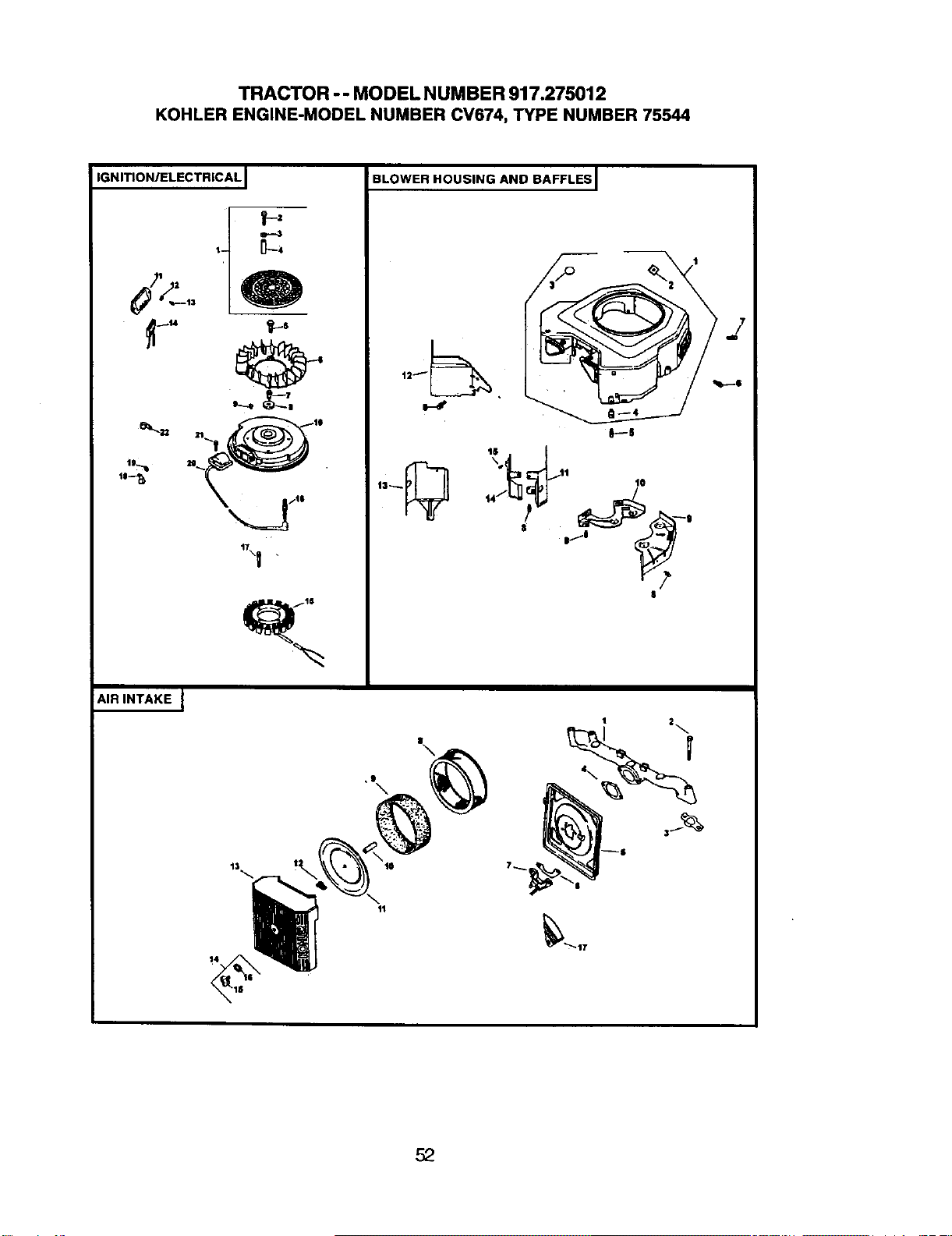
TRACTO R - - MODEL NUM BER 917.275012
KOHLER ENGINE-MODEL NUMBER CV674, TYPE NUMBER 75544
IGNITION/ELECTRICAL I
,,_ -_"_' ,
17\_ •
AIR INTAKE J
BLOWER HOUSING AND BAFFLESJ
_p-.-S
• tl 10
44
t
I
r?
8
1o
11
II
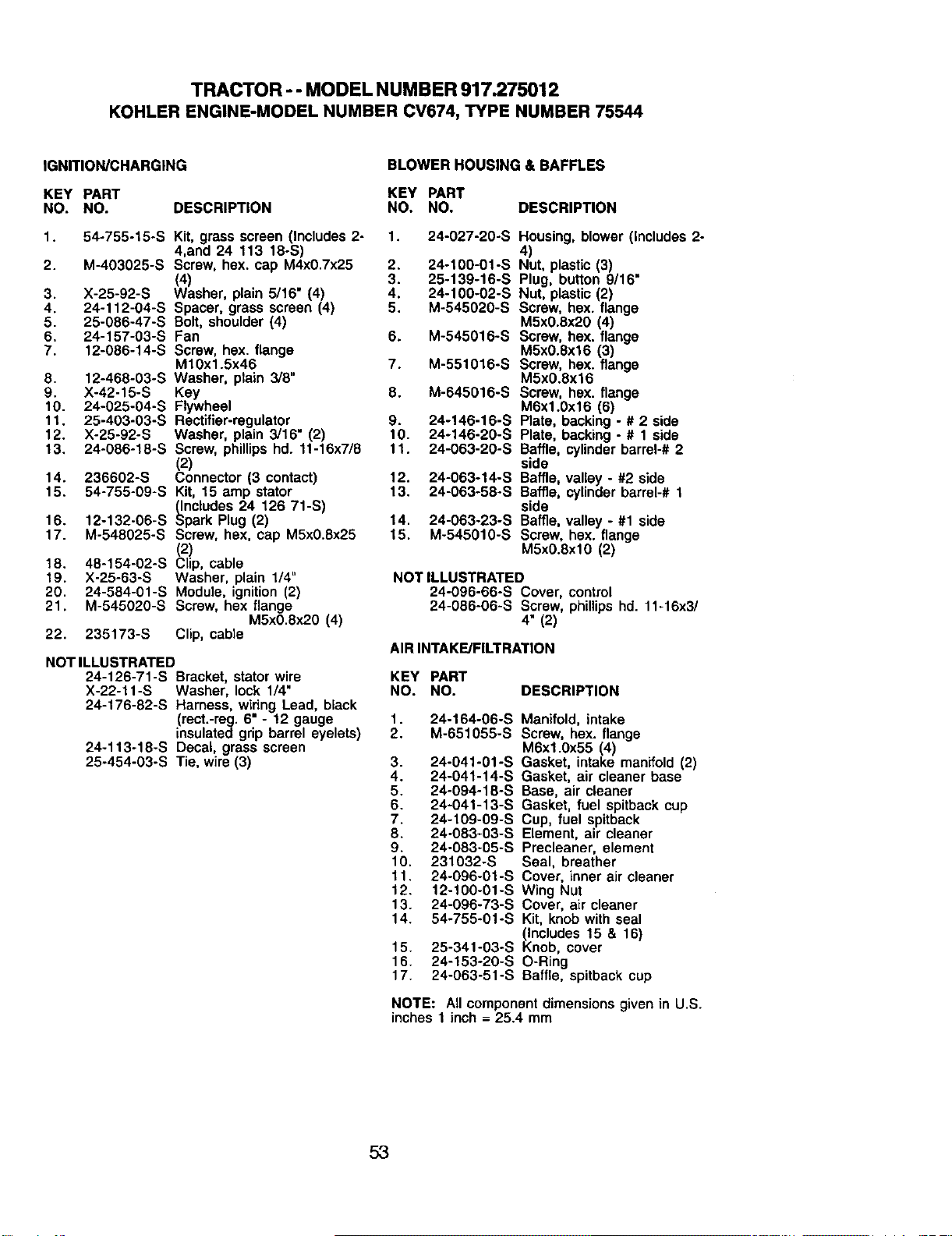
TRACTOR - - MODEL NUMBER 917.275012
KOHLER ENGINE-MODEL NUMBER CV674, TYPE NUMBER 75544
IGNITION/CHARGING BLOWER HOUSING & BAFFLES
KEY PART KEY PART
NO. NO. DESCRIPTION NO. NO. DESCRIPTION
1. 54-755-15-S Kit, grass screen (Includes 2- 1. 24-027-20-S
4,and 24 113 18-S)
2. M-403025-S Screw, hex. cap M4x0.7x25 2. 24-100-01-S
(4) . 3. 25-13g-16-S
3. X-25-92-S Washer, plain 5/16 (4) 4. 24-100-02-S
4. 24-112-04-S Spacer, grass screen (4) 5. M-545020-S
5. 25-086-47-S Bolt, shoulder (4)
6. 24-157-03-S Fan 6. M-545016-S
7. 12-086-14-S Screw, hex. flange
M10x1.5x46 7. M-551016-S
8. 12-468-03-S Washer, plain 3/8"
9. X-42-15-S Key 8. M-645016-S
10. 24-025-04-S Flywheel
11. 25-403-03-S Rectifier-regulator 9. 24-146-16-S
12. X-25-92-S Washer, plain 3/16" (2) 10. 24-146-20-S
13. 24-086-18-S Screw, phillips hd. 11-16x7/8 11. 24-063-20-S
(2)
14. 236602-S Connector (3 contact) 12. 24-063-14-S
15. 54-755-09-S Kit, 15 amp stator 13. 24-063-58-S
(Includes 24 126 71-S)
16. 12-132-06-S Spark Plug (2) 14. 24-063-23-S
17. M-548025-S Screw, hex, cap M5x0.8x25 15. M-545010-S
(2)
18. 48-154-02-S Clip, cable
19. X-25-63-S Washer, plain 1/4"
20. 24-584-01-S Module, ignition (2)
21. M-545020-S Screw, hex flange
M5x0.8x20 (4)
22. 235173-S Clip, cable
Housing, blower (Includes 2-
4)
Nut, plastic (3)
Plug, button 9/16"
Nut, plastic (2)
Screw, hex. flange
M5x0.8x20 (4)
Screw, hex. flange
M5x0.8x16 (3)
Screw, hex. flange
M5x0.8x16
Screw, hex. flange
M6x1.0x16 (6)
Plate, backing - # 2 side
Plate, backing - # 1 side
Baffle, cylinder barrel-# 2
side
Baffle, valley - #2 side
Baffle, cylinder barrel-# 1
side
Baffle, valley - #1 side
Screw, hex. flange
M5x0.8xlO (2)
NOT ILLUSTRATED
24-096-66-S Cover, control
24-086-06-S Screw, phillips hd. 11-16x3/
4" (2)
AIR INTAKE/FILTRATION
NOT ILLUSTRATED
24-126-71-S Bracket, stator wire KEY PART
X-22-11-S Washer, lock 1/4" NO. NO.
24-176-82-S Hamess, widng Lead, black
(rect.-reg. 6" - !2 gauge 1.
insulated grip barrel eyelets) 2.
24-113-18-S Decal, grass screen
25-454-03-S Tie, wire (3)
DESCRIPTION
24-164-06-S
M-651055-S
3. 24-041-01-S
4. 24-041-14-S
5. 24-094-18-S
6. 24-041-13-S
7. 24-109-09-S
8. 24-083-03-S
9. 24-083-05-S
10, 231032-S
11, 24-096-01-S
12. 12-100-01-S
13. 24-096-73-S
14. 54-755-01-S
15. 25-341-03-S
16. 24-153-20-S
17. 24-063-51-S
Manifold, intake
Screw, hex. flange
M6xl.0x55 (4)
Gasket, intake manifold (2)
Gasket, air cleaner base
Base, air cleaner
Gasket, fuel spitback cup
Cup, fuel spitback
Element, air cleaner
Precleaner, element
Seal, breather
Cover, inner air cleaner
Wing Nut
Cover, air cleaner
Kit, knob with seal
(Includes 15 & 16)
Knob, cover
O-Ring
Baffle, spitback cup
NOTE: All component dimensions given in U.S.
inches 1 inch = 25.4 mm
53
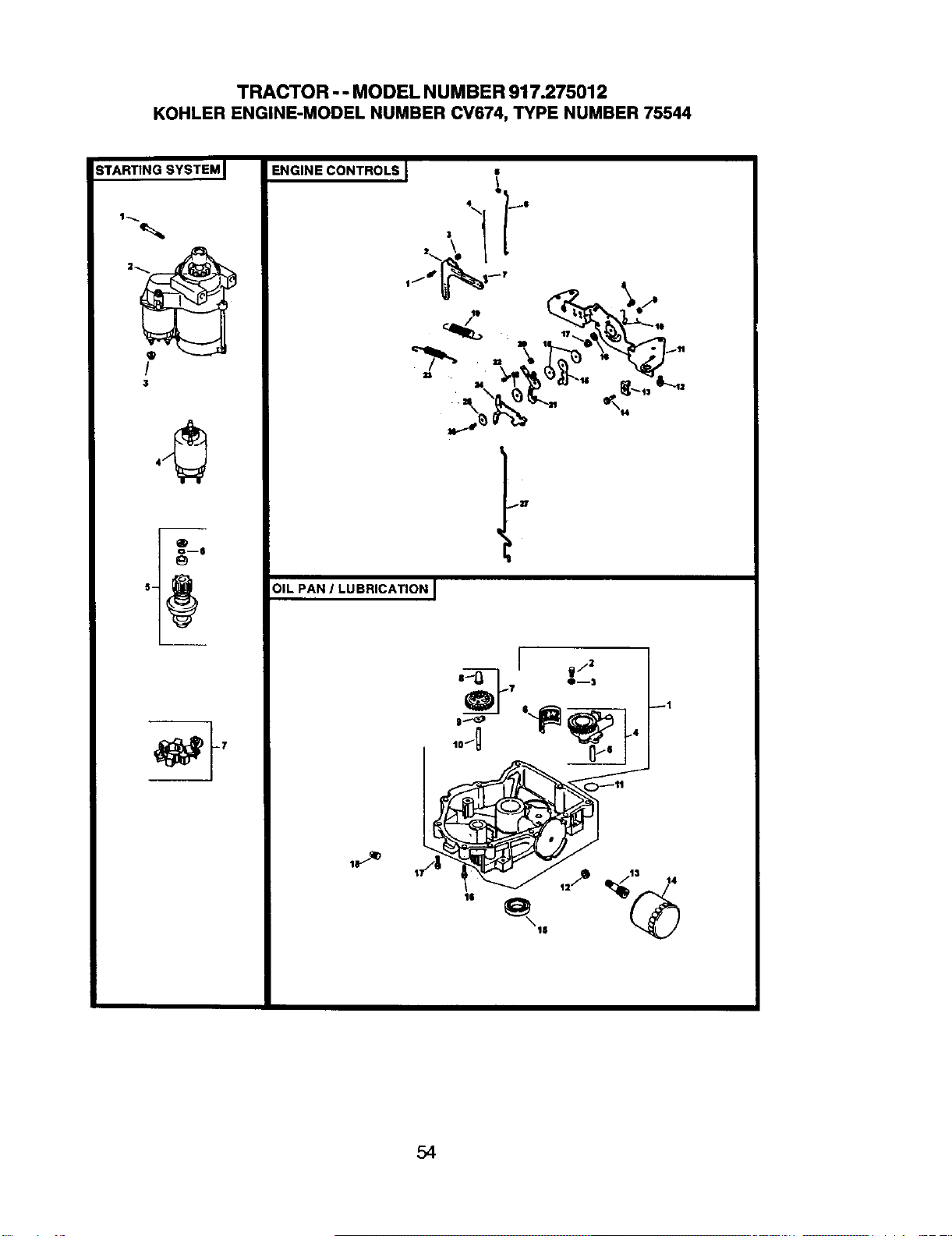
TRACTOR - - MODEL N UMBER 917.275012
KOHLER ENGINE-MODEL NUMBER CV674, TYPE NUMBER 75544
STARTING SYSTEM I
/
3
_6
ENGINE CONTROLS I •
_ '_.
OIL PAN J LUBRICATION J
|
54
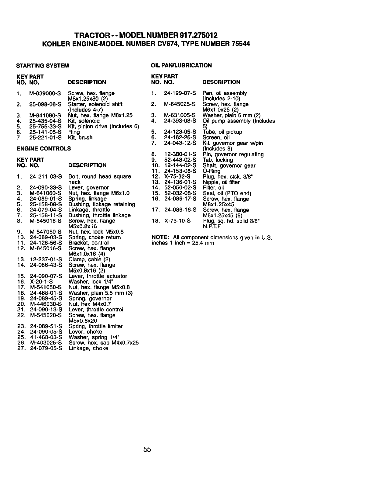
TRACTOR -- MODELNUMBER917.275012
KOI-ILERENGINE-MODELNUMBERCV674,TYPENUMBER75544
STARTING SYSTEM
KEY PART
NO. NO. DESCRIPTION
1. M-839080-S
2. 25-098-08-S
3. M-841080-S
4. 25-435-04-S
5. 25-755-33-S
6. 25-141-05oS
7. 25-221-01-S
Screw, hex. flange
M8x1.25x80 (2)
Starter, solenoid shift
(Includes 4-7)
Nut, hex. flange M8x1.25
Kit, solenoid
Kit, pinion drive (Includes 6)
Ring
Kit, brush
ENGINE CONTROLS
KEYPART
NO. NO.
1. 24 211 03-S
2. 24-090-33-S
3. M-641060-S
4. 24-089-01-S
5. 25-158-08-S
6. 24-079-04-S
7. 25-158-11-S
8. M-545016-S
9. M-547050-S
10. 24-089-03-S
11. 24-126-56-S
12. M-645016-S
13. 12-237-01-S
14. 24-086-43-S
15. 24-090-07°S
16. X-20-1-S
17. M-541050-S
18. 24-468-01-S
19. 24-089-45-S
20. M-446030-S
21. 24-090°13-S
22. M-545020-S
23. 24-089-51-S
24. 24-090-05-S
25. 41-468-03-S
26. M-403025-S
27. 24-079-05-S
DESCRIPTION
Bolt, round head square
neck
Lever, governor
Nut, hex. flange M6xl.0
Spring, linkage
Bushing, linkage retaining
Linkage, throttle
Bushing, throttle linkage
Screw, hex. flange
M5x0.8x16
Nut, hex. lock M5x0.8
Spdng, choke return
Bracket, control
Screw, hex. flange
M6x1.0x16 (4)
Clamp, cable (2)
Screw, hex. flange
M5x0.Sx16 (2)
Lever, throttle actuator
Washer, lock 1/4"
Nut, hex. flange M5x0.8
Washer, plain 5.5 mm (3)
Spring, governor
Nut, hex M4x0.7
Lever, throttle control
Screw, hex. flange
M5x0.8x20
Spring, throttle limiter
Lever, choke
Washer, spring 1/4"
Screw, hex. cap M4x0.7x25
Linkage, choke
OIL PAN/LUBRICATION
KEY PART
NO. NO. DESCRIPTION
1. 24-199-07-S
2. M°645025-S
3. M-631005-S
4. 24-393-08-S
5. 24-123-05-S
6. 24-162-26-S
7. 24-043-12-S
8. 12-380-01-S
9. 52-448-02-S
10. 12-144-02-S
11. 24-153-08-S
12. X-75-32-S
13. 24-136-01-S
14. 52-050-02-S
15. 52-032-08-S
16. 24-086-17-S
17. 24-086-16-S
18. X-75-10-S
Pan, oil assembly
(Includes 2-10)
Screw, hex. flange
M6x1.0x25 (2)
Washer, plain 6 mm (2)
Oil pump assembly (Includes
5)
Tube, oil pickup
Screen, oil
Kit, governor gear w/pin
(Includes 8)
Pin, governor regulating
Tab, locking
Shaft, governor gear
O-Ring
Plug, hex, ctsk. 3/8"
Nipple, oil filter
Filter, oil
Seal, oil (PTO end)
Screw, hex. flange
M8xl.25x45
Screw, hex. flange
M8x1.25x45 (9)
Plug, sq. hd. solid 3/8"
N.P.T.F.
NOTE: All component dimensions given in U,S.
inches 1 inch = 25.4 mm
55
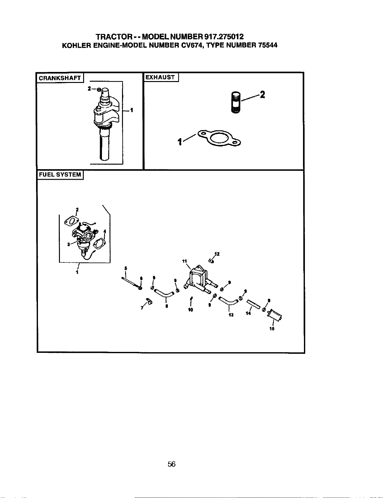
TRACTOR - - MODEL NUM BER 917.275012
KOHLER ENGINE-MODEL NUMBER CV674, TYPE NUMBER 75544
:RANKSHAFT I
FUELSYSTEMJ
2--1
rl
EXHAUST J
/
t
16
56
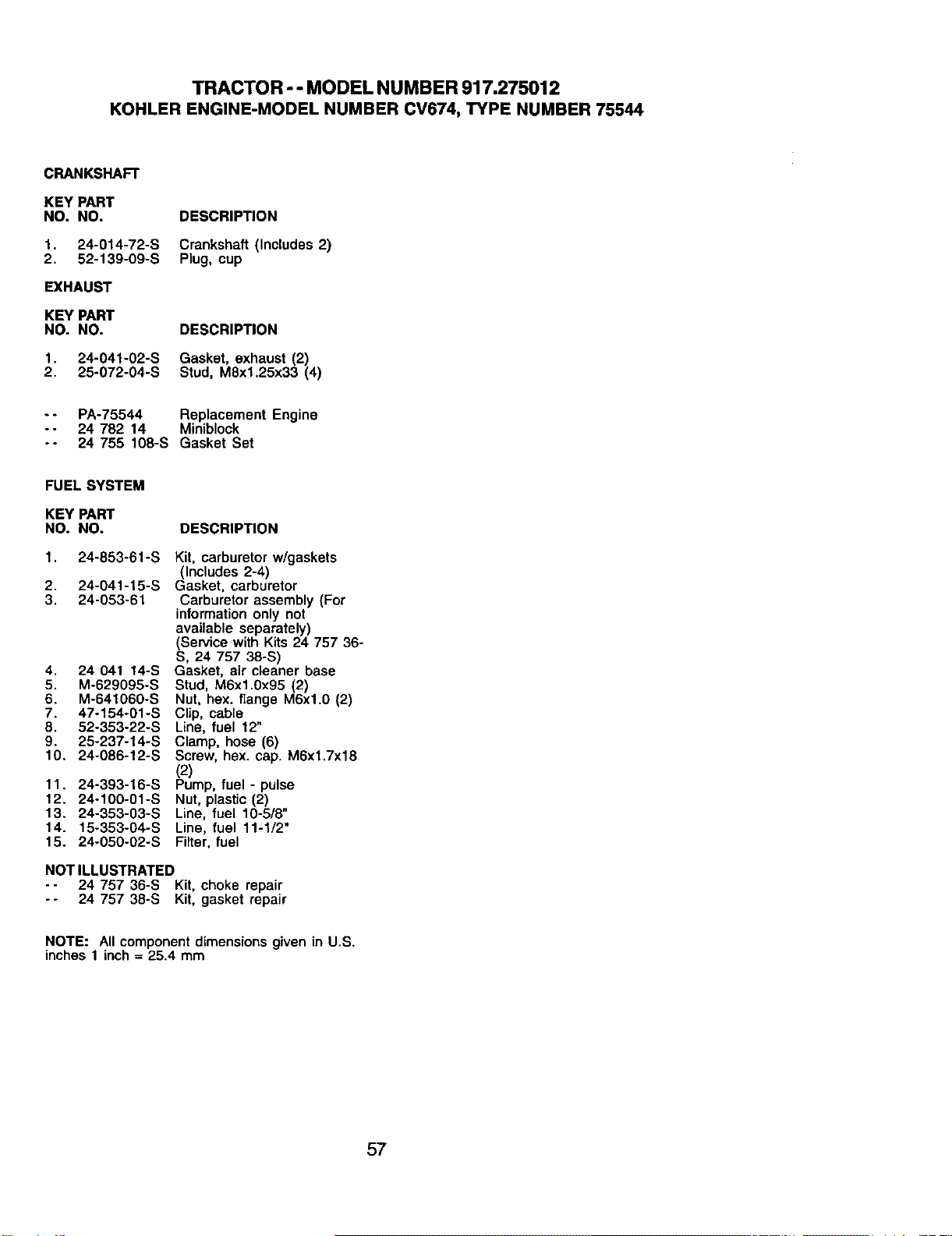
TRACTOR - - MODEL NUMBER 917.275012
KOHLER ENGINE-MODEL NUMBER CV674, TYPE NUMBER 75544
CRANKSHAFT
KEY PART
NO. NO. DESCRIPTION
1. 24-014-72-S Crankshaft (Includes2)
2. 52-139-09-S Plug, cup
EXHAUST
KEY PART
NO. NO. DESCRIPTION
1. 24-041-02-S Gasket, exhaust (2)
2. 25o072-04-S Stud, M8xl.25x33 (4)
-- PA-75544 Replacement Engine
-- 24 782 14 Miniblock
-- 24 755 108-S Gasket Set
FUEL SYSTEM
KEY PART
NO. NO. DESCRIPTION
1. 24-853-61-S
2. 24-041-15-S
3. 24-053-61
4. 24 041 t4-S
5. M-629095-S
6. M-64106O-S
7. 47-154-01-S
8. 52-353-22-S
9. 25-237-14-S
10. 24-086-t 2-S
11. 24-393-16-S
12. 24-1g0-01-S
13. 24-353-03-S
14. 15-353-04-S
15. 24-050-02-S
Kit, carburetor w/gaskets
(Includes 2-4)
Gasket, carburetor
Carburetor assembly (For
information only not
available separately)
(Service with Kits 24 757 36-
S, 24 757 38-S)
Gasket, air cleaner base
Stud, M6x1.0x95 (2)
Nut, hex. flange M6xl.0 (2)
Clip, cable
Line, fuel 12"
Clamp, hose (6)
Screw, hex. cap. M6x1.7x18
(2)
Pump, fuel - pulse
Nut, plastic (2)
Line, fuel 10-5/8"
Line, fuel 11-1/2"
Filter, fuel
NOT ILLUSTRATED
-- 24 757 36-S Kit, choke repair
-- 24 757 38-S Kit, gasket repair
NOTE: All component dimensions given in U.S.
inches 1 inch = 25.4 mm
57

58

SUGGESTED GUIDE FOR SIGHTING SLOPES FOR SAFE OPERATION
_L ARNING: To avoid serious Injury, operate your tractor up and
down the face of slopes, never across the face. Do not mow
slopes greater than 15 degrees. Make turns gradually to prevent
tipping or loss of control. Exercise extreme caution when
changing direction on slopes.
1. Fold this page along dotted line indicated above.
2. Hold page before you so that its left edge is vertically parallel to a tree
trunk or other upright structure.
3, Sight across the fold in the direction of hill slope you want to measure.
4. Compare the angle of the fold with the slope of the hill.
For repairofmajor brand appliancesin your own home...
nomatter whomade it,no matter whosold
1-800-4-MY-HOME _
(1-8(X)-469-4663)
WWW.SeEirs.corn
Forrepairofcarry-inproducts likevacuums,lawnequipment,and
electronics,callforthe nearest Sears Parts and RepairCenter.
1-800-488-1222 AnyUme,dayorr_ghqU.SAore)
W,seEy_Colln
For the replacement parts, accessories and owner's manuals
that you need to do-it-yourself, call Sears PartsDirectSM!
1-800-366-PART 6a.m.-11 p.m.,7daysaweek
(1-800-,366-7278) (U.SA only)
_.se_'s.q_n/parlsdirect
To purchase or inquireabout a Sears Service Agreement
or Sears Maintenance Agreement:
1-800-827-6655 (u.sA) 1-800-361-6665 (Canada)
7 a.m.- 5 p.m.,CST,Mort.- Sat. 9 a-re.- 8 p.m.EST,M- F,4 p.m.S_.
Parape_r serviciode _-=,parac_a
domic_io,ypara ordenarpiezas:
1.888-SU.HOGARsM
(1-888-784-6427)
Au Canadapourse_ice enIran£ais:
1.800-LE-FOYER"c
(1-80o-533-6937)
WWW.Seafs.ca
© Seats,RcebuckandCo.
HomeCentral®J
® Registered Trademark / TMTrademark / SMService Mark ofSears, Roebuck and Co.
® Marca Registrada / TMMarca de Fdbdca / su Marca de Servicio de Sears, Roebuck and Co.
uc Marque de commerce / MOMarque d_posde de Sears, Roebuck and Co.
182733 2.1.02 TR Printed in U.S.A.


