x p a n s
I I II I
I IIII
Model No. 831.2971 50
Serial No.
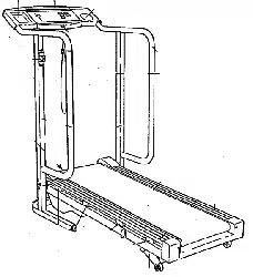
The serial number is found in the location
shown below. Write the serial number in
the space above for future reference.
Serial Number Decal
EXERCISE
E (:_ U I P M E N T
H E_LPLi N E£ !
1-800-736-6879
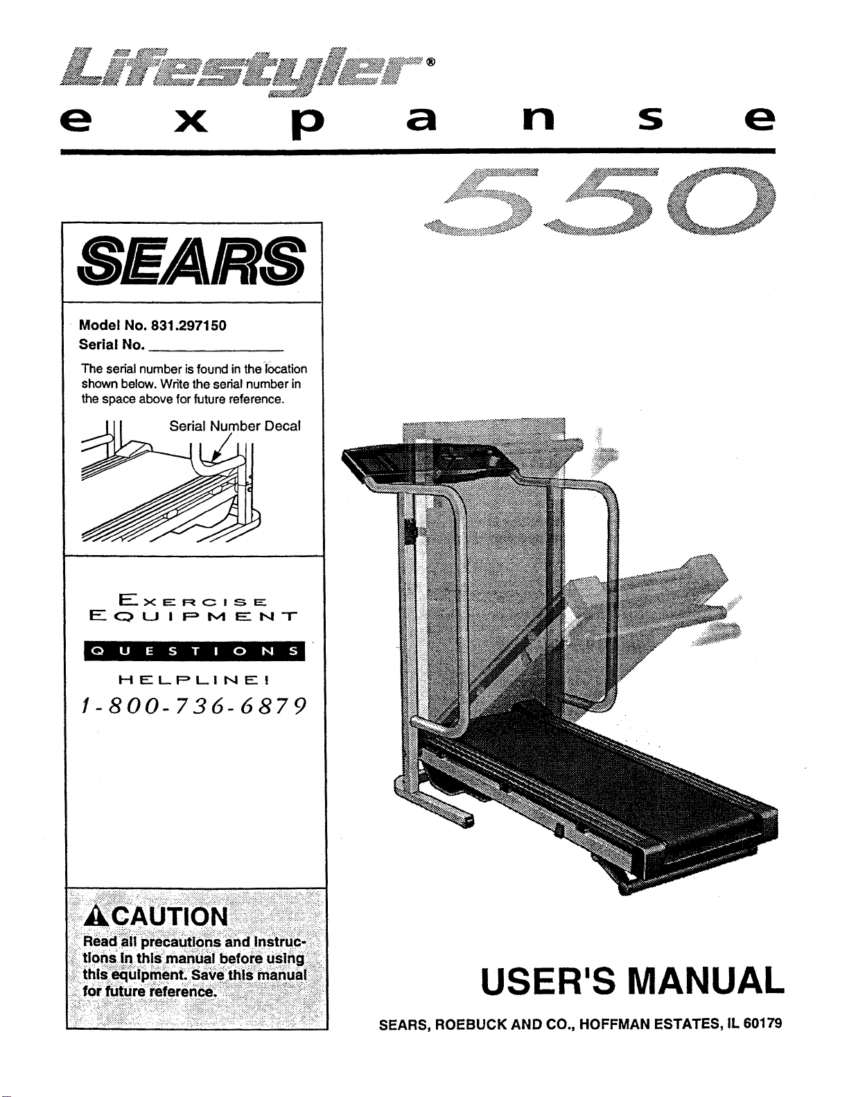
USER'S MANUAL
SEARS, ROEBUCK AND CO., HOFFMAN ESTATES, IL 60179
TABLE OF CONTENTS
IMPORTANT PRECAUTIONS ................................................................. 2
BEFORE YOU BEGIN ....................................................................... 4
ASSEMBLY ............................................................................... 5
OPERATION AND ADJUSTMENT ............................................................. 7
HOW TO FOLD AND MOVE THE TREADMILL .................................................. 10
TROUBLE-SHOOTING ..................................................................... 12
CONDITIONING GUIDELINES ............................................................... 14
ORDERING REPLACEMENT PARTS ......... . ........................................ Back Cover
FULL 90 DAY WARRANTY ........................................................... Back Cover
Note: An EXPLODED DRAWING and a PART LIST are attached to the center of this manual. Save the
EXPLODED DRAWING and PART LIST for future reference.
IMPORTANT PRECAUTIONS
2
!:::!:)
?i::!:!:i:i;i;i:!:;:!:i:!:!;!:i:i:!
?i •
13. Never move the walking belt while the 18. You must be able to safely lift 45 Pouhds (20 :
power is turned off. Do not operate the kg) to raise, lower, or move the treadmilh:::;_:_::::;:;:_i
tr_admill if the power cord or plug is dam-_ • _ _ ii ii L'I _: :i : :.i I :: _i ;
__ag_bd,_orff thetreadmill Is not workin_"prop - ___i"19_When _ioidingorm0Ving the_treadmiil, make i:i_
erly, (Se_ BEFORE YOU BEGIN On page4 if _ : .sure that theestorage iatChis fully closed. "
ii the treadmill is not working properly.):._.: . ' : _
14. Never start the treadmill while_youare _: ....i " every three _onths.: i-i;::;ii.-.-:i!!:_i:: i ill: i -::.!:.: '
this or an_ _-......
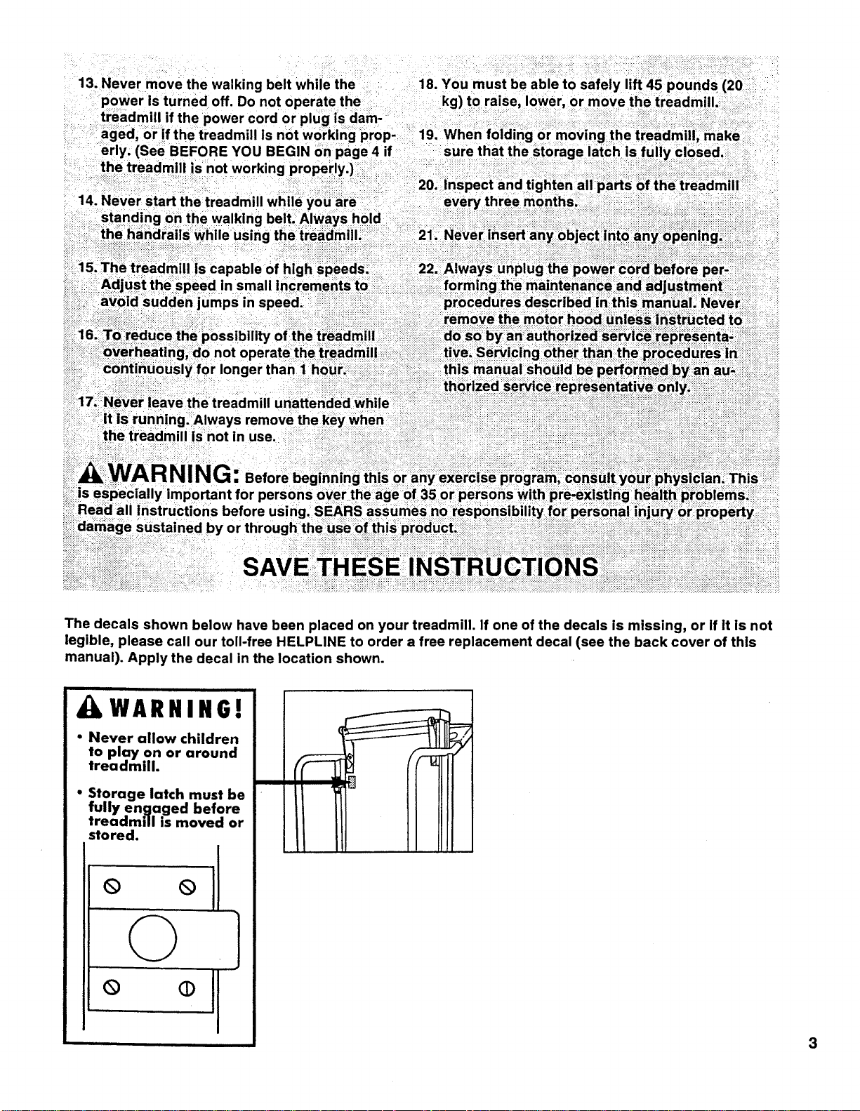
The decals shown below have been placed on your treadmill. If one of the decals is missing, or If it is not
legible, please call our toll-free HELPLINE to order a free replacement decal (see the back cover of this
manual). Apply the decal in the location shown.
WARNING!
• Never allow children
to play on or around
treadmill.
• Storage latch must be
fully engaged before
treadmill is moved or
stored.
° °11
©
3
BEFORE YOU BEGIN
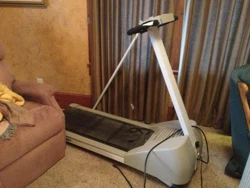
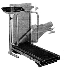
Thank you for selecting the SEARS LIFESTYLER ®
EXPANSE 550 treadmill. The EXPANSE 550 treadmill
blends advanced technology with innovative design to
let you enjoy an excellent form of cardiovascular exer-
cise in the convenience and privacy of your home.
For your benefit, read this manual carefully before
using the treadmill, if you have additional questions,
please call our toll-free HELPLINE at 1-800-736-6879,
Monday through Saturday, 7 a.m. until 7 p.m. Central
Time (excluding holidays). To help us assist you,
please note the product model number and serial num-
ber before calling. The model number of the treadmill
is 831.297150. The serial number can be found on a
decal attached to the treadmill (see the front cover of
this manual for the location).
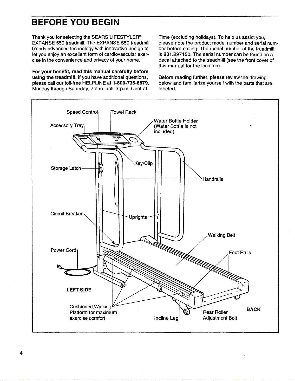
Before reading further, please review the drawing
below and familiarize yourself with the parts that are
labeled.
Speed Control ,wel Rack
Bottle Holder •
(Water Bottle is not
included)
Storage
Circuit
Power Cord
andrails
Belt
Foot Rails
LEFT SIDE
Cushioned .Walking
Platform for maximum
exercise comfort
Incline Leg
Rear Roller
Adjustment Bolt
BACK
4
ASSEMBLY
CAUTION: Carefully read and follow step 1 below before removing the restraining tie (see drawing 1
below). If the restraining tie is removed prematurely, serious bodily injury may result. Assembly requires
two people. Set the treadmill in a cleared area and remove the packing materials, except for the restraining tie.
Do not dispose of the packing materials until assembly is completed. Assembly requires the following tools (not
included): A phillips screwdriver ,,_ and a 3/8" wrench '_ O.
.
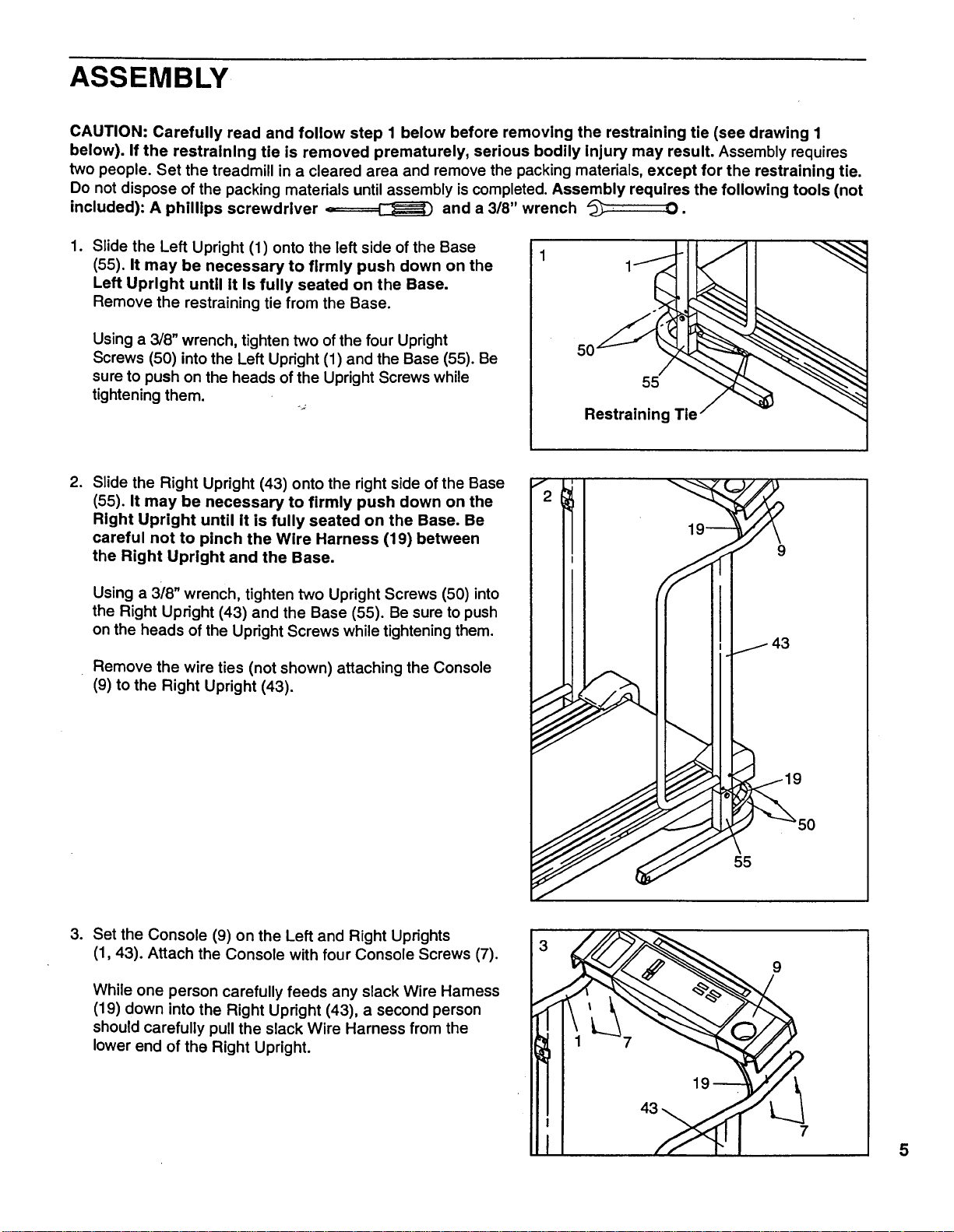
Slide the Left Upright (1) onto the left side of the Base
(55). It may be necessary to firmly push down on the
Left Upright until it Is fully seated on the Base.
Remove the restraining tie from the Base.
Using a 3/8" wrench, tighten two of the four Upright
Screws (50) into the Left Upright (1) and the Base (55). Be
sure to push on the heads of the Upright Screws while
tightening them.
5O
55
RestrainingTie
.
Slide the Right Upright (43) onto the right side of the Base
(55). It may be necessary to firmly push down on the
Right Upright until it is fully seated on the Base. Be
careful not to pinch the Wire Harness (19) between
the Right Upright and the Base.
Using a 3i8" wrench, tighten two Upright Screws (50) into
the Right Upright (43) and the Base (55). Be sure to push
on the heads of the Upright Screws while tightening them.
Remove the wire ties (not shown) attaching the Console
(9) to the Right Upright (43).
9
5O
55
.
Set the Console (9) on the Left and Right Uprights
(1, 43). Attach the Console with four Console Screws (7).
While one person carefully feeds any slack Wire Hamess
(19) down into the Right Upright (43), a second person
should carefully pull the slack Wire Harness from the
lower end of the Right Upright.
5
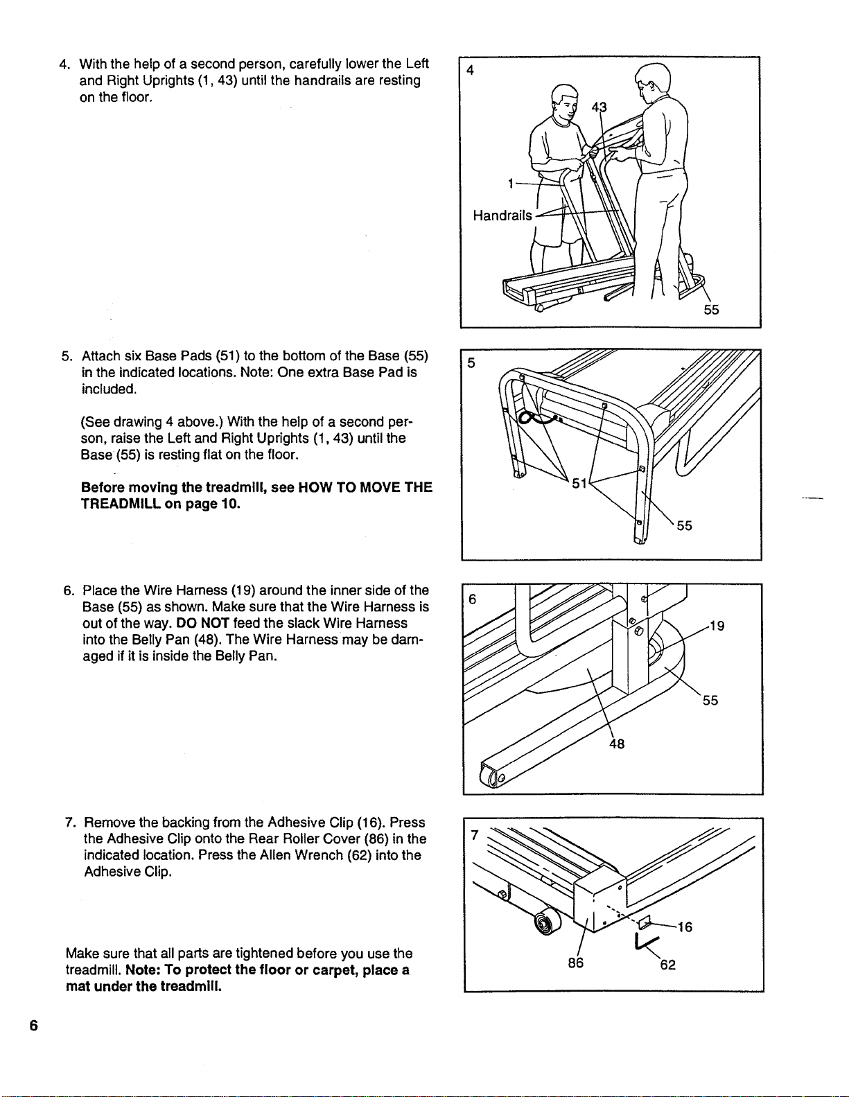
4. With the help of a second person, carefully lower the Left
and Right Uprights (1,43) until the handrails are resting
on the floor.
43
, I
Han
55
o
Attach six Base Pads (51) to the bottom of the Base (55)
in the indicated locations. Note: One extra Base Pad is
included.
(See drawing 4 above.) With the help of a second per-
son, raise the Left and Right Uprights (1,43) until the
Base (55) is resting flat on the floor.
Before moving the treadmill, see HOW TO MOVE THE
TREADMILL on page 10.
6,
Place the Wire Harness (19) around the inner side of the
Base (55) as shown. Make sure that the Wire Harness is
out of the way. DO NOT feed the slack Wire Harness
into the Belly Pan (48). The Wire Harness may be dam-
aged if it is inside the Belly Pan.
55
48
7. Remove the backing from the Adhesive Clip (16). Press
the Adhesive Clip onto the Rear Roller Cover (86) in the
indicated location. Press the Allen Wrench (62) into the
Adhesive Clip.
Make sure that all parts are tightened before you use the
treadmill. Note: To protect the floor or carpet, place a
mat under the treadmill.
L<
86 62
16
6
OPERATION AND ADJUSTMENT
THE PERFORMANT LUBE TM WALKING BELT
Your treadmill features a walking belt coated with
PERFORMANT LUBE TM, a high-performance lubricant.
IMPORTANT: Never apply silicone spray or other
substances to the walking belt or the walking plat-
form. They will deteriorate the walking belt and
cause excessive wear.
HOW TO PLUG IN THE POWER CORD
electric shock. This product is equipped with a cord
having an equipment-grounding conductor and a
grounding plug. Plug the power cord into a surge
protector, and plug the surge protector into an ap-
propriate outlet that is properly installed and
grounded in accordance with all local codes and
ordinances.
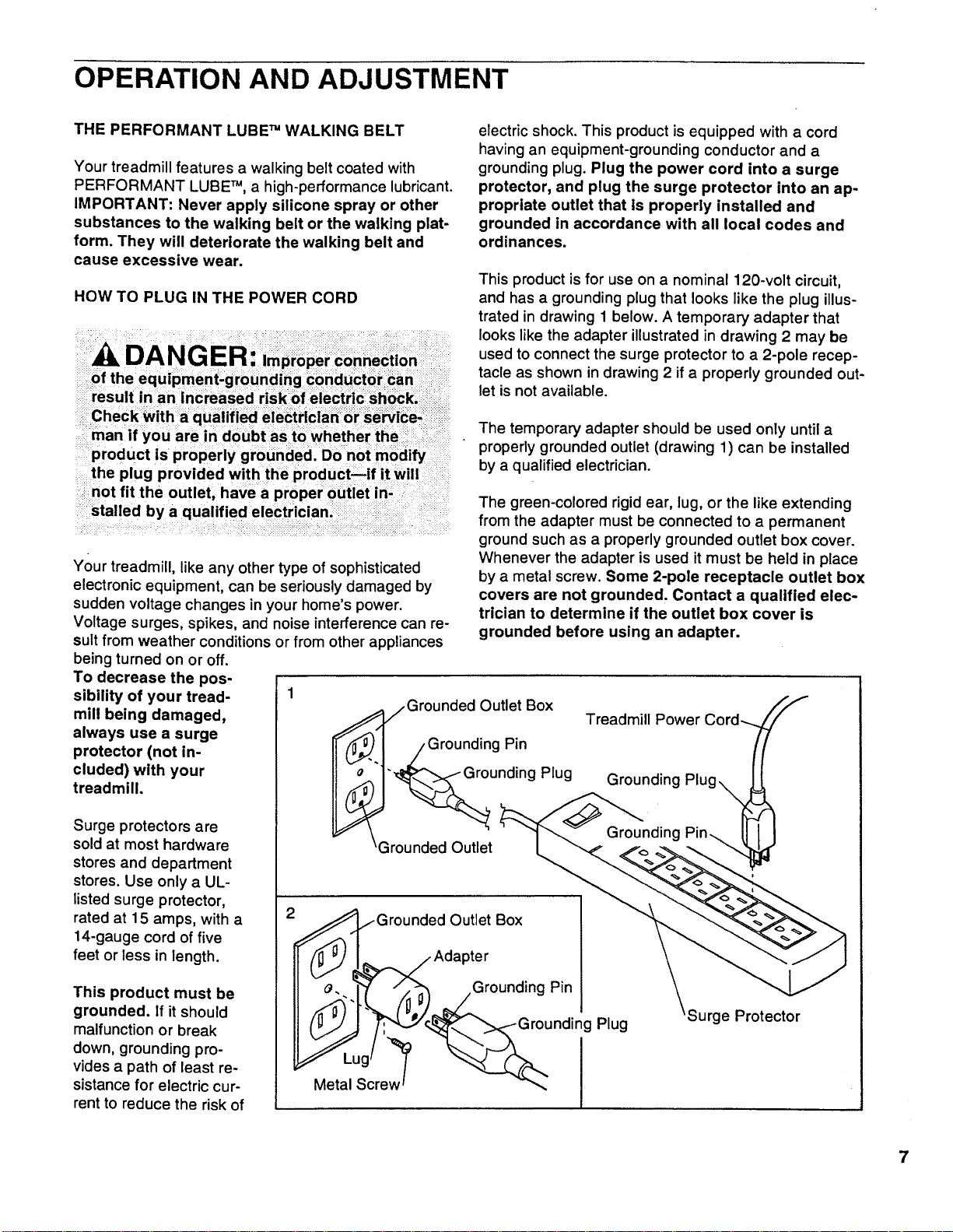
This product isfor use on a nominal 120-volt circuit,
and has a grounding plug that looks like the plug illus-
trated in drawing 1 below. A temporary adapter that
looks like the adapter illustrated in drawing 2 may be
used to connect the surge protector to a 2-pole recep-
tacle as shown in drawing 2 if a properly grounded out-
let is not available.
_ Check With a qualified electrician or Service-! :::ii_
ilmanif you are in doubt as to whether the i i:::::I_
product is properly grounded. Do not modify
the plug provided with the product--if it will
not fit the outlet, have a proper outlet in-
stalled by a qualified electrician, i
Your treadmill, like any other type of sophisticated
electronic equipment, can be seriously damaged by
sudden voltage changes in your home's power.
Voltage surges, spikes, and noise interference can re-
sult from weather conditions or from other appliances
being turned on or off.
To decrease the pos-
sibility of your tread- 1
mill being damaged,
always use a surge
protector (not in-
cluded) with your
treadmill.
Surge protectors are
sold at most hardware
stores and department
stores. Use only a UL-
listed surge protector,
rated at 15 amps, with a
14-gauge cord of five
feet or less in length.
This product must be
grounded. If it should
malfunction or break
down, grounding pro-
vides a path of least re-
sistance for electric cur-
rent to reduce the risk of
The temporary adapter should be used only until a
properly grounded outlet (drawing 1) can be installed
by a qualified electrician.
The green-colored rigid ear, lug, or the like extending
from the adapter must be connected to a permanent
ground such as a properly grounded outlet box cover.
Whenever the adapter is used it must be held in place
by a metal screw. Some 2-pole receptacle outlet box
covers are not grounded. Contact a qualified elec-
trician to determine if the outlet box cover is
grounded before using an adapter.
/Grounded Outlet Box
nding Pin
nding
\Grounded Outlet
Plug
Treadmill Power
Plug
Surge Protector
7
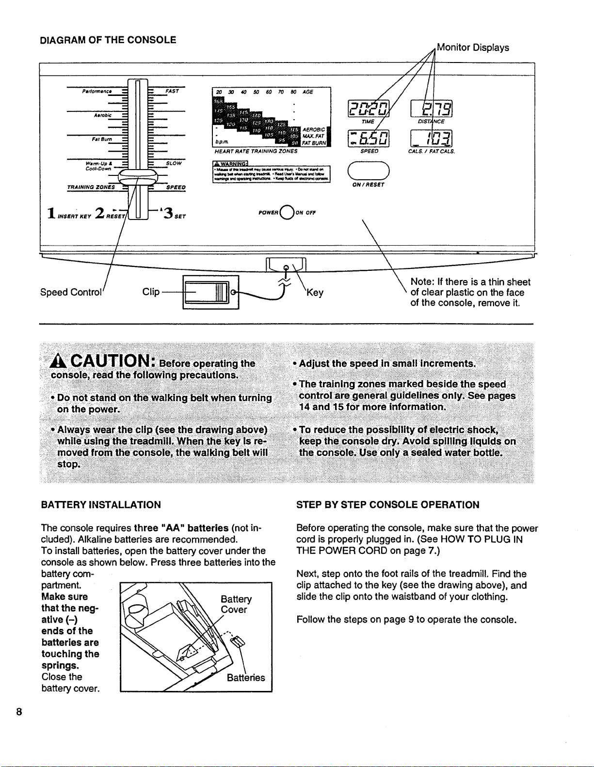
DIAGRAM OF THE CONSOLE Monitor Displays
...........
-p.,......__-__i i=_AST _ o_,0__,oE_
,.E.... _ ;.,.o_,,TE_RJ t-6.:_uJ 1.,£_1
-- HEART RATE TRAINING ZONES SPEED CALS. / FAT CALS.
wJ_-up i = = sLOW
Cool.Oov, n_
TRAINING ZONES " -// -- "" SPEED
/
1,NSS.;..2_ --'3.T
"L.
Speed Control /
POWER OON OFF
IL •d!
ON / RESET
\'\\
ir
Note: If there is a thin sheet
of clear plastic on the face
of the console, remove it.
BATTERY INSTALLATION
The console requires three "AA" batteries (not in-
cluded). Alkaline batteries are recommended.
To install batteries, open the battery cover under the
console as shown below. Press three batteries intothe
battery com-
partment.
Make sure
that the neg-
ative (-)
ends of the
batteries are
touching the
springs.
Close the
battery cover.
Battery
Cover
des
STEP BY STEP CONSOLE OPERATION
Before operating the console, make sure that the power
cord is properly plugged in. (See HOW TO PLUG IN
THE POWER CORD on page 7.)
Next, step onto the foot rails of the treadmill. Find the
clip attached to the key (see the drawing above), and
slide the clip onto the waistband of your clothing.
Follow the steps on page 9 to operate the console.
8
i]
Insert the key fully into the power switch.
Inserting the key will
not turn on the dis- .o.,.C)0, 0.
plays. The displays will
turn on when the
ON/RESET button is
pressed or when the
walking belt is started.
Note: If you just in-
stalled batteries, the displays will already be on.
CALORIES/FAT CAL-
ORIES display--This
display shows the ap-
proximate numbers of
calories and fat calories
you have burned. (See
FAT CALORIES on
page 14 for an explanation of fat calories.) Every
seven seconds, the display will change from one
number to the other. Arrows in the display will indi-
cate which number is currently shown.
Arrows
A
CALS. / FATCALS.
B
lg
Reset the speed control.
Slide the speed control
down to the RESET po-
sition. Note: Each time
the walking belt is
stopped, the speed
control must be moved
to the RESET position
before the walking belt
can be restarted.
Start the walking belt.
After you have moved the speed control to the
RESET position, slowly slide it upward untilthe
walking belt begins to move at slow speed.
Carefully step onto the walking belt and begin exer-
cising. Change the speed of the walking belt as de-
sired by sliding the speed control.
To stop the walking belt, step onto the foot rails and
slide the speed control to the RESET position.
Follow your progress with the monitor displays.
TIME display--This
display shows the total
time that you have
walked or run on the
treadmill.
-ln.- nl
L-U-L-u !
TIME
DISTANCE display--
This display shows the
total distance that you
have walked or run, in
miles.
SPEED display--This
display shows the speed
ofthe walking belt, in
miles per hour.
DIS TANCE
I"" F F FII
. LT. LI I
SPEED
The displays can be
reset, if desired, by
pressing the ON/RESET
button.
ON / RESET
When you are finished exercising, stop the
walking belt and remove the key.
Step onto the foot rails, stop the walking belt, and
remove the key from the console. Store the key in a
secure place. After the key is removed, the dis-
plays will remain on for about five minutes.
Note: Any time that the walking belt is stopped
and no console buttons are pressed for five
minutes, the displays will automatically turn off
in order to conserve the batteries.
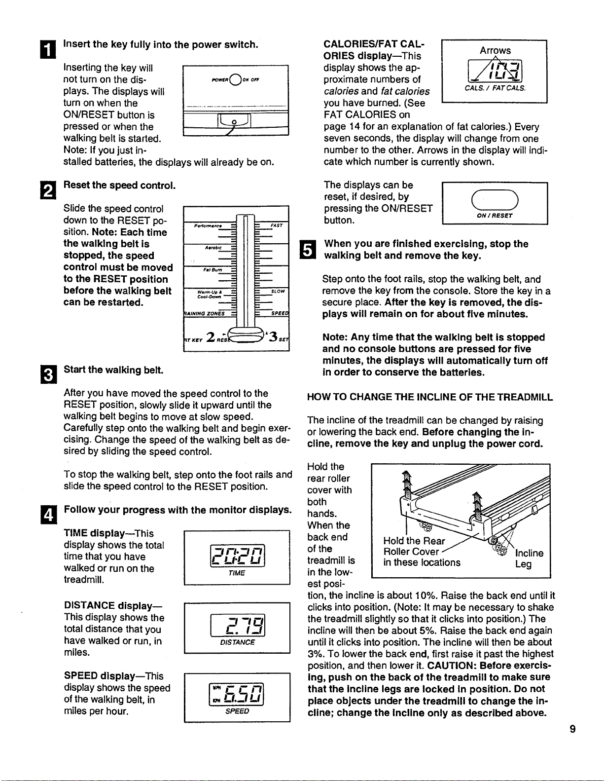
HOW TO CHANGE THE INCLINE OF THE TREADMILL
The incline of the treadmill can be changed by raising
or lowering the back end. Before changing the in-
cline, remove the key and unplug the power cord.
Hold the
rear roller
cover with
both
hands.
When the
back end
of the
treadmill is
in the low-
est posi-
Hold the Rear
Roller Cover Incline
in these locations Leg
tion, the incline is about 10%. Raise the back end until it
clicks into position. (Note: It may be necessary to shake
the treadmill slightly so that it clicks into position.) The
incline will then be about 5%. Raise the back end again
until it clicks into position. The incline will then be about
3%. To lower the back end, first raise it past the highest
position, and then lower it. CAUTION: Before exercis-
ing, push on the back of the treadmill to make sure
that the Incline legs are locked in position. Do not
place objects under the treadmill to change the in-
cline; change the incline only as described above.
9
HOW TO FOLD AND MOVE THE TREADMILL
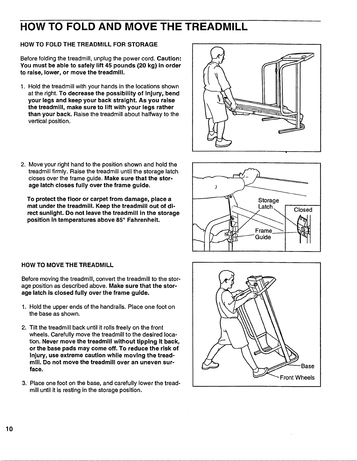
HOW TO FOLD THE TREADMILL FOR STORAGE
Before folding the treadmill, unplug the power cord. Caution:
You must be able to safely lift 45 pounds (20 kg) in order
to raise, lower, or move the treadmill.
1,
Hold the treadmill with your hands in the locations shown
at the right. To decrease the possibility of Injury, bend
your legs and keep your back straight. As you raise
the treadmill, make sure to lift with your legs rather
than your back. Raise the treadmill about halfway to the
vertical position.
,
Move your right hand to the position shown and hold the
treadmill firmly. Raise the treadmill until the storage latch
closes over the frame guide. Make sure that the stor-
age latch closes fully over the frame guide.
To protect the floor or carpet from damage, place a
mat under the treadmill. Keep the treadmill out of di-
rect sunlight. Do not leave the treadmill in the storage
position in temperatures above 85° Fahrenheit.
Storage
Closed
HOW TO MOVE THE TREADMILL
Before moving the treadmill, convert the treadmill to the stor-
age position as described above. Make sure that the stor-
age latch is closed fully over the frame guide.
1. Hold the upper ends of the handrails. Place one foot on
the base as shown.
,
Tilt the treadmill back until it rolls freely on the front
wheels. Carefully move the treadmill to the desired loca-
tion. Never move the treadmill without tipping it back,
or the base pads may come off. To reduce the risk of
Injury, use extreme caution while moving the tread-
mill. Do not move the treadmill over an uneven sur-
face.
3. Place one foot on the base, and carefully lower the tread-
mill until it is resting in the storage position.
Front Wheels
10
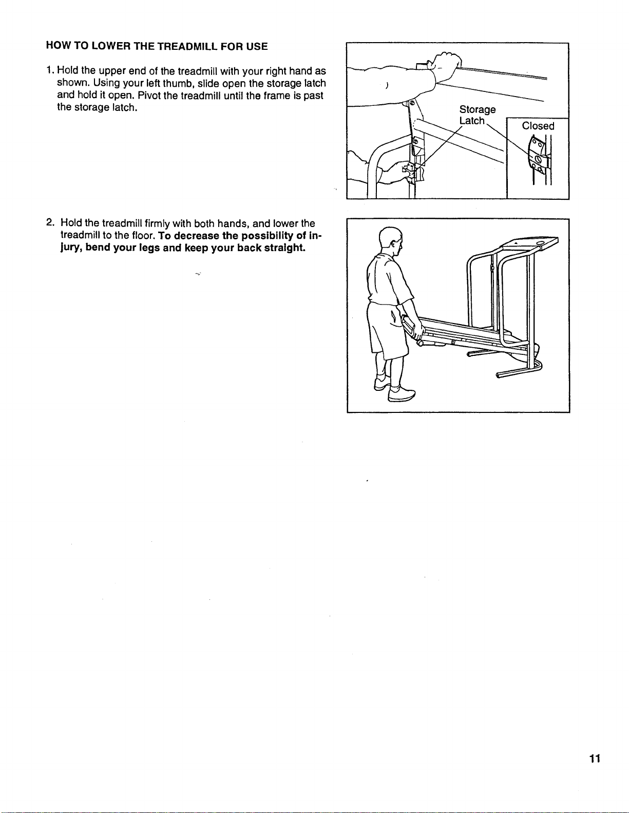
HOW TO LOWER THE TREADMILL FOR USE
1. Hold the upper end of the treadmill with your right hand as
shown. Using your left thumb, slide open the storage latch
and hold it open. Pivot the treadmill until the frame is past
the storage latch.
Storage
Latch
Closed
2. Hold the treadmill firmly with both hands, and lower the
treadmill to the floor. To decrease the possibility of in-
jury, bend your legs and keep your back straight.
11
TROUBLE-SHOOTING
Most treadmill problems can be solved by following the simple steps below. Find the symptom that ap-
plies, and follow the steps listed. If further assistance is needed, call our toll-free HELPLINE at 1-800-736-
6879, Monday through Saturday, 7 a,m. until 7 p.m. Central Time (excluding holidays).
1. SYMPTOM: THE POWER DOES NOT TURN ON
a.
Make sure that the power cord is plugged into a surge protector, and that the surge protector is plugged into
a properly grounded outlet. (See HOW TO PLUG IN THE POWER CORD on page 7.) Use only a UL-listed
surge protector, rated at 15 amps, with a 14-gauge cord of five feet or less in length.
b.
C.
After the power cord has been plugged in, make sure that the key is fully inserted intothe console. (See step
1 on page 9.)
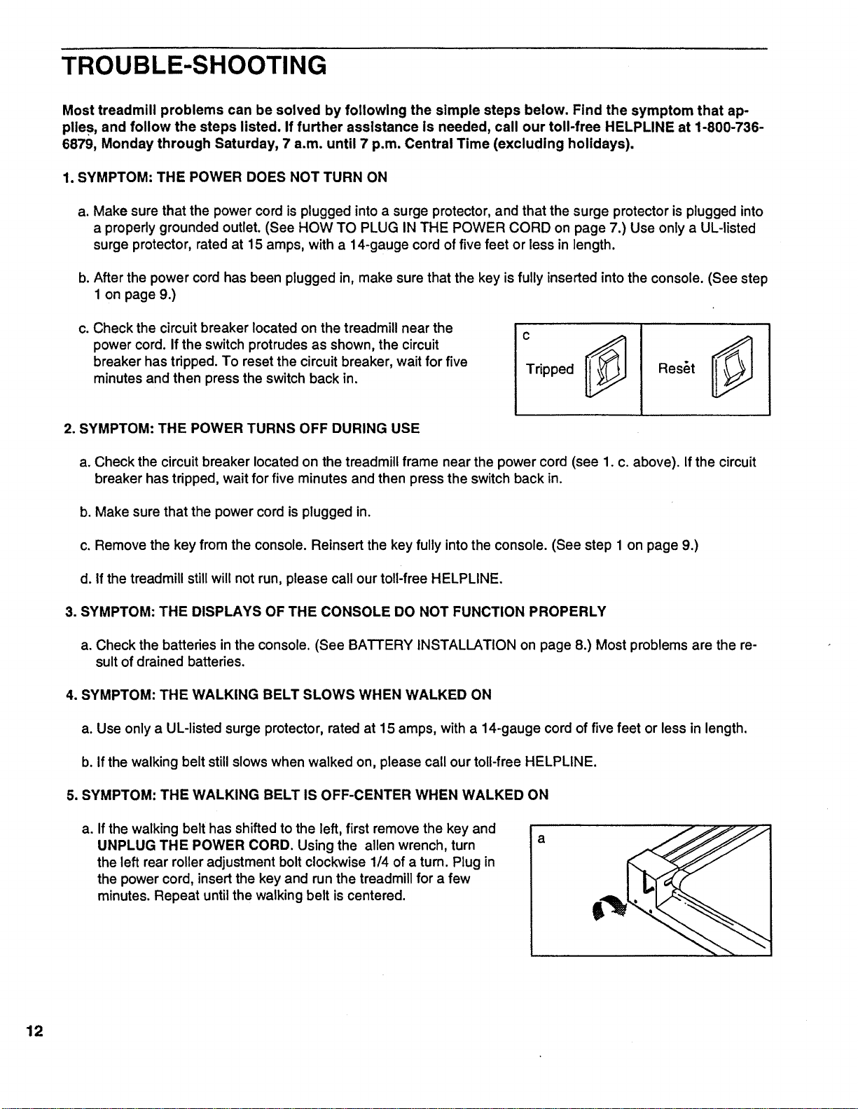
Check the circuit breaker located on the treadmill near the
power cord. Ifthe switch protrudes as shown, the circuit
breaker has tripped. To reset the circuit breaker, wait for five
minutes and then press the switch back in.
2. SYMPTOM: THE POWER TURNS OFF DURING USE
C
Tripped
Reset
a. Check the circuit breaker located on the treadmill frame near the power cord (see 1. c. above). If the circuit
breaker has tripped, wait for five minutes and then press the switch back in.
b. Make sure that the power cord is plugged in.
c. Remove the key from the console. Reinsert the key fully intothe console. (See step 1 on page 9.)
d. If the treadmill stillwill not run, please call our toll-free HELPLINE.
3. SYMPTOM: THE DISPLAYS OF THE CONSOLE DO NOT FUNCTION PROPERLY
a. Check the batteries in the console. (See BATTERY INSTALLATION on page 8.) Most problems are the re-
sult of drained batteries.
4. SYMPTOM: THE WALKING BELT SLOWS WHEN WALKED ON
a. Use only a UL-listed surge protector, rated at 15 amps, with a 14-gauge cord of five feet or less in length.
b. If the walking belt still slows when walked on, please call our toll-free HELPLINE.
5. SYMPTOM: THE WALKING BELT IS OFF-CENTER WHEN WALKED ON
a. Ifthe walking belt has shiftedto the left, first remove the key and
UNPLUG THE POWER CORD. Using the allen wrench, turn a
the left rear roller adjustment boltclockwise 1/4 of a turn. Plug in
the power cord, insert the key and run the treadmill for a few
minutes. Repeat untilthe walking belt iscentered.
12
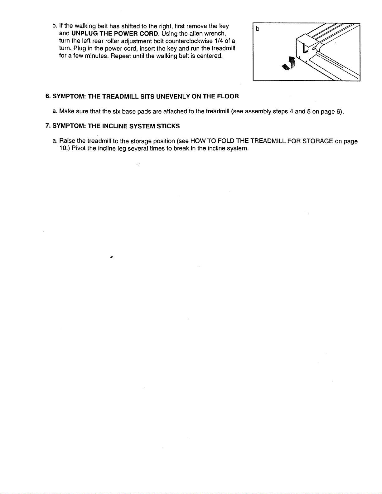
b. If the walking belt has shifted to the right, first remove the key
and UNPLUG THE POWER CORD. Using the allen wrench,
turn the left rear roller adjustment bolt counterclockwise 1/4 of a
turn. Plug in the power cord, insert the key and run the treadmill
for a few minutes. Repeat until the walking belt is centered.
b
6. SYMPTOM: THE TREADMILL SITS UNEVENLY ON THE FLOOR
a. Make sure that the six base pads are attached to the treadmill (see assembly steps 4 and 5 on page 6).
7. SYMPTOM: THE INCLINE SYSTEM STICKS
a. Raise the treadmill to the storage position (see HOW TO FOLD THE TREADMILL FOR STORAGE on page
10.) Pivot the incline leg several times to break in the inclinesystem.
CONDITIONING GUIDELINES
14
ii:i_ii:with pre=existinghealth
The following guidelines will help you to plan your ex-
ercise program. Remember_hese are general guide-
lines only. For more detaited exercise information, ob-
tain a reputable book or consult your physician.
EXERCISE INTENSITY
Whether your goal is to burn fat or to strengthen your
cardiovascular system, the key to achieving the de-
sired results is to exercise with the proper intensity.
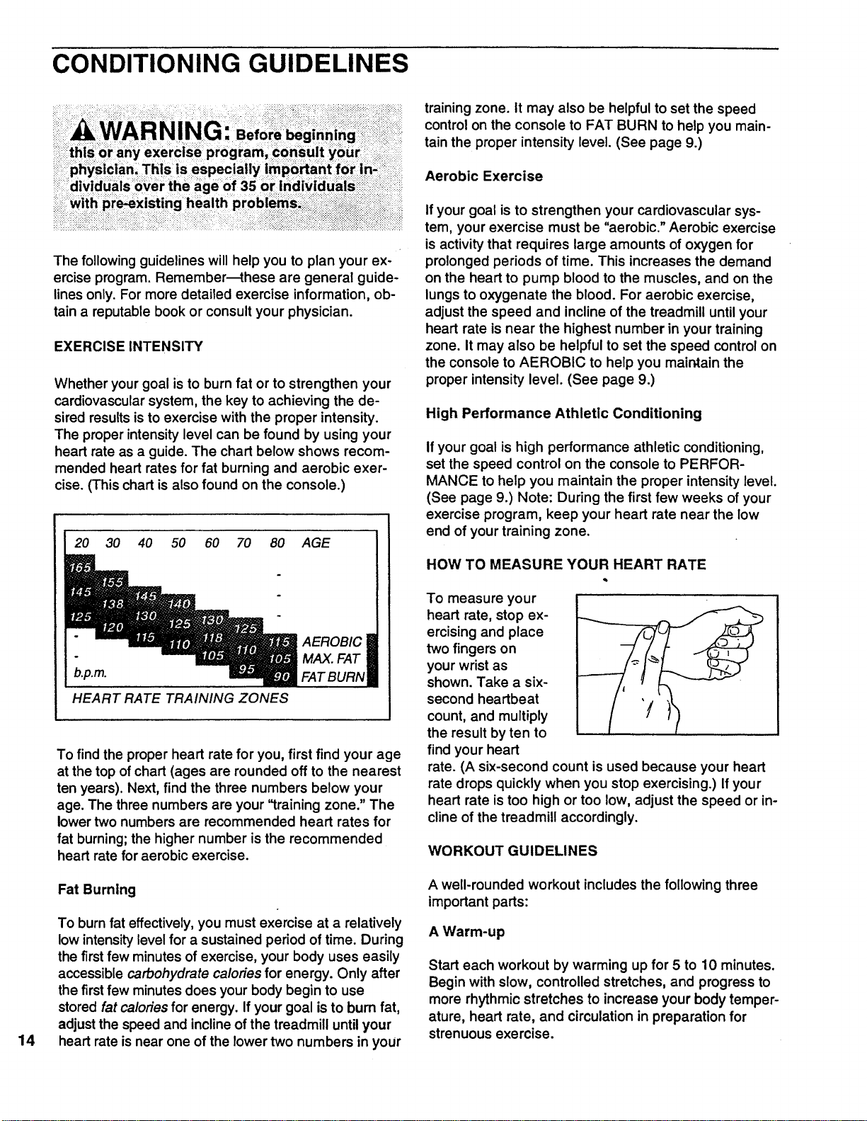
The proper intensity level can be found by using your
heart rate as a guide. The chart below shows recom-
mended heart rates for fat burning and aerobic exer-
cise. (This chart is also found on the console.)
20 30 40 50 60 70 80
b.p.m.
HEART RATE TRAINING ZONES
AGE
AEROBIC I
MAX. FAT
FAT BURNll
To find the proper heart rate for you, first find your age
at the top of chart (ages are rounded off to the nearest
ten years). Next, find the three numbers below your
age. The three numbers are your '_raining zone." The
lower two numbers are recommended heart rates for
fat burning; the higher number is the recommended
heart rate for aerobic exercise.
Fat Burning
To burn fat effectively, you must exercise at a relatively
low intensitylevel for a sustained period of time. During
the firstfew minutes of exercise, your body uses easily
accessible carbohydrate calories for energy. Only after
the firstfew minutes does your body begin to use
stored fat calories for energy. If your goal is to bum fat,
adjustthe speed and inclineof the treadmill until your
heart rate isnear one of the lower two numbers in your
training zone. It may also be helpful to set the speed
control on the console to FAT BURN to help you main-
tain the proper intensity level. (See page 9.)
Aerobic Exercise
If your goal is to strengthen your cardiovascular sys-
tem, your exercise must be "aerobic." Aerobic exercise
is activity that requires large amounts of oxygen for
prolonged periods of time. This increases the demand
on the heart to pump blood to the muscles, and on the
lungs to oxygenate the blood. For aerobic exercise,
adjust the speed and incline of the treadmill until your
heart rate is near the highest number in your training
zone. It may also be helpful to set the speed control on
the console to AEROBIC to help you maintain the
proper intensity level. (See page 9.)
High Performance Athletic Conditioning
Ifyour goal is high performance athletic conditioning,
set the speed control on the console to PERFOR-
MANCE to help you maintain the proper intensity level.
(See page 9.) Note: During the first few weeks of your
exercise program, keep your heart rate near the low
end of your training zone.
HOW TO MEASURE YOUR HEART RATE
To measure your
heart rate, stop ex-
ercising and place
two fingers on
your wrist as
shown. Take a six-
second heartbeat
count, and multiply
the result by ten to
find your heart
rate. (A six-second count is used because your heart
rate drops quickly when you stop exercising.) If your
heart rate is too high or too low, adjust the speed or in-
cline of the treadmill accordingly.
WORKOUT GUIDELINES
A well-rounded workout includes the following three
important parts:
A Warm-up
Start each workout by warming up for 5 to 10 minutes.
Begin with slow, controlled stretches, and progress to
more rhythmic stretches to increase your body temper-
ature, heart rate, and circulation in preparation for
strenuous exercise.
Training Zone Exercise
After warming up, increase the intensity of your exer-
cise until your pulse is in your training zone for 20 to
60 minutes. (During the first few weeks of your exer-
cise program, do not keep your pulse in your training
zone for longer than 20 minutes.) Breathe regularly
and deeply as you exercise---never hold your breath.
A Cool-down
Finish each workout with 5 to 10 minutes of stretching
to cool down. This will increase the flexibility of your
muscles and will help to prevent post-exercise problems.
Exercise Frequency
To maintain or improve your condition, complete three
workouts each week, with at least one day of rest be-
tween workouts. After a few months, you may com-
plete up to five workouts each week if desired.
The key to success is to make exercise a regular and
enjoyable part of your everyday life.
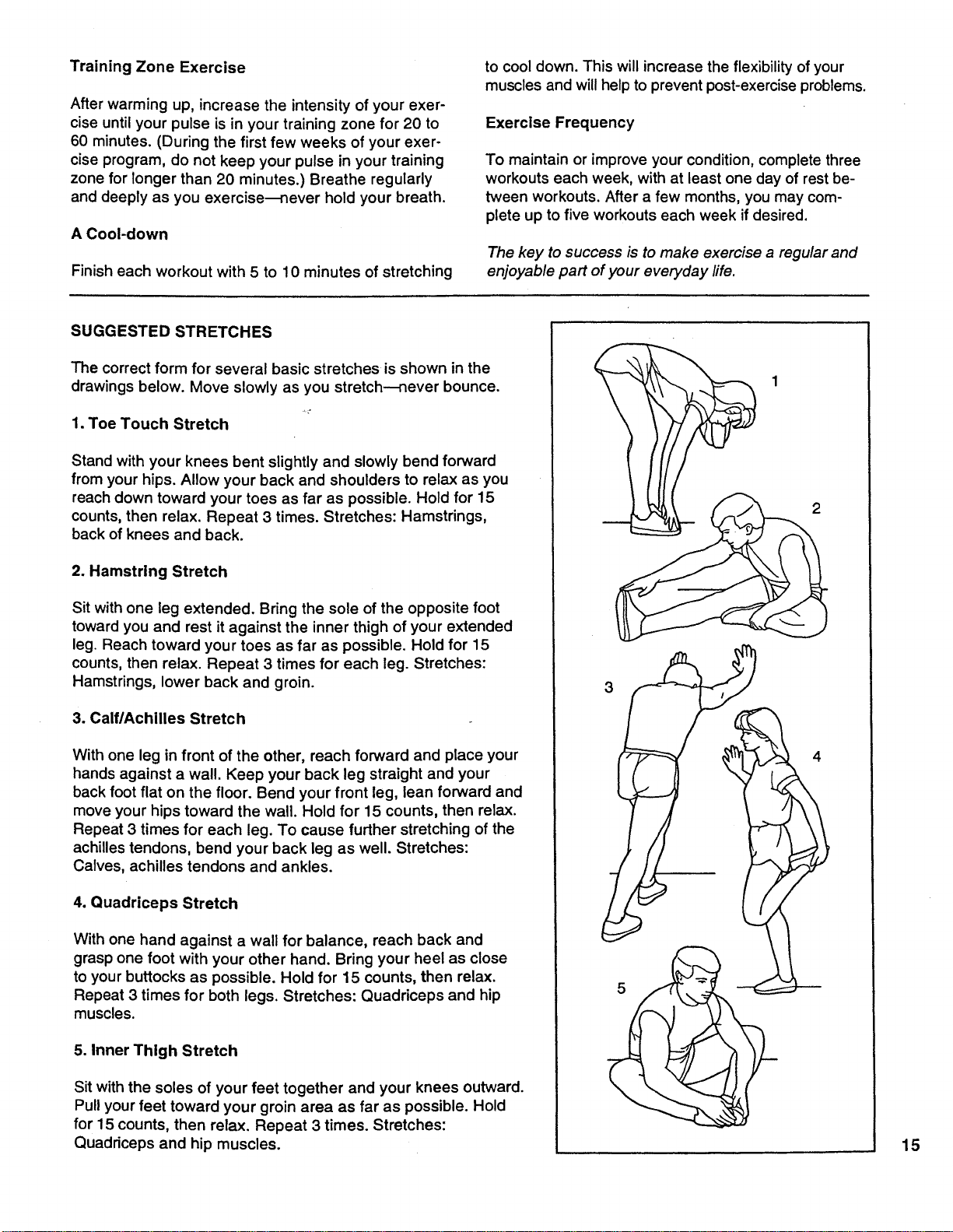
SUGGESTED STRETCHES
The correct form for several basic stretches is shown in the
drawings below. Move slowly as you stretch--never bounce.
1. Toe Touch Stretch
Stand with your knees bent slightly and slowly bend forward
from your hips. Allow your back and shoulders to relax as you
reach down toward your toes as far as possible. Hold for 15
counts, then relax. Repeat 3 times. Stretches: Hamstrings,
back of knees and back.
2. Hamstring Stretch
Sit with one leg extended. Bring the sole of the opposite foot
toward you and rest it against the inner thigh of your extended
leg. Reach toward your toes as far as possible. Hold for 15
counts, then relax. Repeat 3 times for each leg. Stretches:
Hamstrings, lower back and groin.
3. Calf/Achilles Stretch
With one leg in front of the other, reach forward and place your
hands against a wall. Keep your back leg straight and your
back foot flat on the floor. Bend your front leg, lean forward and
move your hips toward the wall. Hold for 15 counts, then relax.
Repeat 3 times for each leg. To cause further stretching of the
achilles tendons, bend your back leg as well. Stretches:
Calves, achilles tendons and ankles.
4. Quadriceps Stretch
With one hand against a wall for balance, reach back and
grasp one foot with your other hand. Bring your heel as close
to your buttocks as possible. Hold for 15 counts, then relax.
Repeat 3 times for both legs. Stretches: Quadriceps and hip
muscles.
5. Inner Thigh Stretch
Sit with the soles of your feet together and your knees outward.
Pull your feet toward your groin area as far as possible. Hold
for 15 counts, then relax. Repeat 3 times. Stretches:
Quadriceps and hip muscles.
3
5
15
IJlJll II
REMOVE THIS EXPLODED DRAWING
AND PART LIST FROM FHE MANUAL
Save this EXPLODED DRAWING and PART LIST for future reference.
I1[ IIIIIII
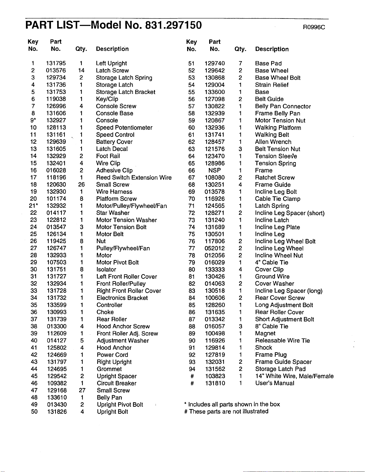
Note: Specifications are subject to change without notice. For information about
ordering replacement parts, see the back cover of the User's Manual.
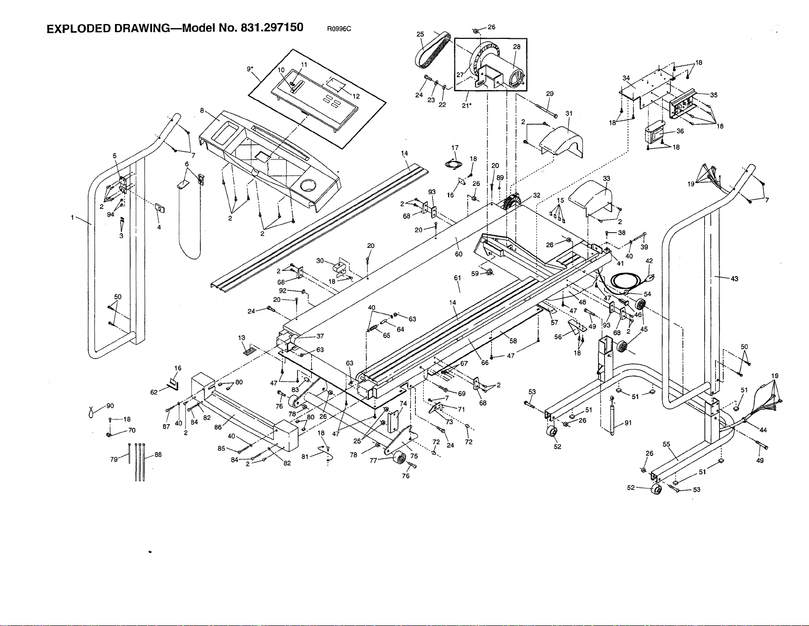
EXPLODED DRAWING--Model No. 831.297150
6
16
13
/
_,80 47
R0996C
78
20
76
29
61
\
14
72
53
52
31
18
34
oo'
33
26
55
18
5O
51
49
19
PART LISTmModel NO. 831.297150 RO996c
Key Part Key
No. No. Qty. Description No.
Part
No. Qty.
Description
1 131795 1 Left Upright 51
2 013576 14 Latch Screw 52
3 129734 2 Storage Latch Spring 53
4 131736 1 Storage Latch 54
5 131753 1 Storage Latch Bracket 55
6 119038 1 Key/Clip 56
7 126996 4 Console Screw 57
8 131606 1 Console Base 58
9* 132927 1 Console 59
10 128113 1 Speed Potentiometer 60
11 131161 • 1 Speed Control 61
12 129639 1 Battery Cover 62
13 131605 1 Latch Decal 63
14 132929 2 Foot Rail 64
15 132401 4 Wire Clip 65
16 016028 2 Adhesive Clip 66
17 118196 1 Reed Switch Extension Wire 67
18 120630 26 Small Screw 68
19 132930 1 Wire Harness 69
20 101174 8 Platform Screw 70
21 * 132932 1 Motor/Pulley/Flywheel/Fan 71
22 014117 1 Star Washer 72
23 122812 1 Motor Tension Washer 73
24 013547 3 Motor Tension Bolt 74
25 126134 1 Motor Belt 75
26 119425 8 Nut 76
27 126747 1 Pulley/Flywheel/Fan 77
28 132933 1 Motor 78
29 107503 1 Motor Pivot Bolt 79
30 131751 8 Isolator 80
31 131727 1 Left Front Roller Cover 81
32 132934 1 Front Roller/Pulley 82
33 131728 1 Right Front Roller Cover 83
34 131732 1 Electronics Bracket 84
35 133599 1 Controller 85
36 130993 1 Choke 86
37 131739 1 Rear Roller 87
38 013300 4 Hood Anchor Screw 88
39 112609 1 Front Roller Adj. Screw 89
40 014127 5 Adjustment Washer 90
41 125802 4 Hood Anchor 91
42 124669 1 Power Cord 92
43 131797 1 Right Upright 93
44 124695 1 Grommet 94
45 129542 2 Upright Spacer #
46 109382 1 Circuit Breaker #
47 129168 27 Small Screw
48 133610 1 Belly Pan
49 013430 2 Upright Pivot Bolt ,
50 131826 4 Upright Bolt
129740 7
129642 2
130868 2
129004 1
133600 1
127098 2
130822 1
132939 1
120867 1
132936 1
131741 1
128457 1
121576 3
123470 1
128986 1
NSP 1
108080 2
130251 4
013578 1
116926 1
124565 1
128271 2
131240 1
131689 1
130501 1
117806 2
052012 2
012056 2
016029 1
133333 4
130426 1
014063 2
130518 1
100606 2
128260 1
131635 1
013342 1
016057 3
100498 1
116926 1
129814 1
127819 1
132031 2
131562 2
103823 1
131810 1
Base Pad
Base Wheel
Base Wheel Bolt
Strain Relief
Base
Belt Guide
Belly Pan Connector
Frame Belly Pan
Motor Tension Nut
Walking Platform
Walking Belt
Allen Wrench
Belt Tension Nut
Tension Sleeqe
Tension Spring
Frame
Ratchet Screw
Frame Guide
Incline Leg Bolt
Cable Tie Clamp
Latch Spring
Incline Leg Spacer (short)
Incline Latch
Incline Leg Plate
Incline Leg
Incline Leg Wheel Bolt
Incline Leg Wheel
Incline Wheel Nut
4" Cable Tie
Cover Clip
Ground Wire
Cover Washer
Incline Leg Spacer (long)
Rear Cover Screw
Long Adjustment Bolt
Rear Roller Cover
Short Adjustment Bolt
8" Cable Tie
Magnet
Releasable Wire Tie
Shock
Frame Plug
Frame Guide Spacer
Storage Latch Pad
14" White Wire, Male/Female
User's Manual
* Includes all parts shown in the box
# These parts are not illustrated

ModelNo.831.297150
QUESTIONS?
If you find that:
• you need help assembling or
operating the EXPANSE 550
treadmill
• a part is missing
• or you need to schedule repair
service
call our toll-free HELPLINE
1-800-736-6879
Monday-Saturday, 7 am-7 pm
Central Time (excluding holidays)
REPLACEMENT
PARTS
If parts become worn and need
to be replaced, call the following
toll-free number
1-800-FON-PART
(1-800-366-7278)
The model number and serial number of your EXPANSE 550 tread-
mill are listed on a decal attached to the frame. See the front cover
of this manual to find the location of the decal.
All replacement parts are available for immediate purchase or
special order when you visit your nearest SEARS Service Center.
To request service or to order parts by telephone, call the toll-free
numbers listed at the left.
When requesting help or service, or ordering parts, please be pre-
pared to provide the following information:
• The NAME OF THE PRODUCT (SEARS LIFESTYLER ®EX-
PANSE 550 treadmill)
• The MODEL NUMBER OF THE PRODUCT (831.297150)
• The PART NUMBER OF THE PART (see the EXPLODED
DRAWING and PART LIST included in this manual)
• The DESCRIPTION OF THE PART (see the EXPLODED DRAW-
ING and PART LIST included in this manual).
FULL 90 DAY WARRANTY
For 90 days from the date of purchase, if failure occurs due to defect in material or workmanship in this
SEARS TREADMILL EXERCISER, contact the nearest SEARS Service Center throughout the United
States and SEARS will repair or replace the TREADMILL EXERCISER, free of charge.
This warranty does not apply when the TREADMILL EXERCISER is used commercially or for rental pur-
poses.
This warranty gives you specific legal rights, and you may also have other rights which vary from state
to state.
SEARS, ROEBUCK AND CO., DEPT. 817WA, HOFFMAN ESTATES, IL 60179
Part No. 131810 F03010BC R0996C Printed in USA © 1996 Sears, Roebuck and Co.