Loading ...
Loading ...
Loading ...
ASSEMBLY / PRE-OPERATION
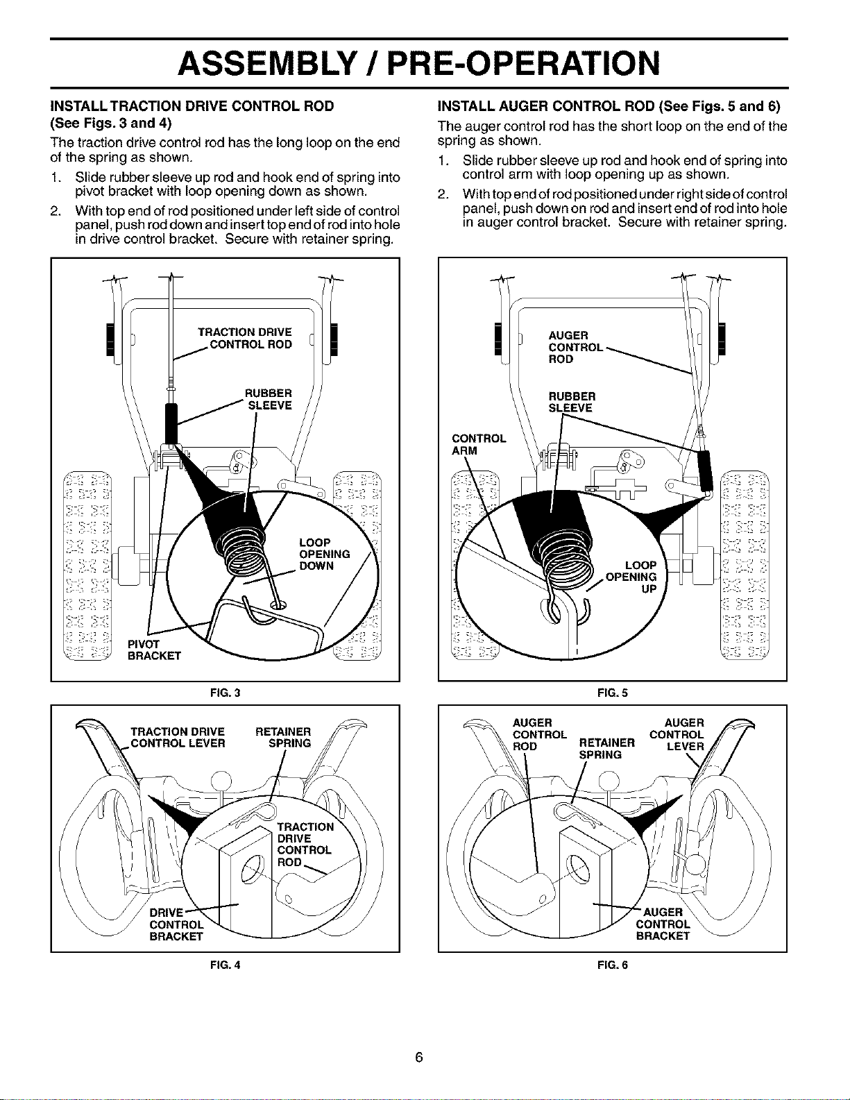
INSTALLTRACTION DRIVE CONTROL ROD
(See Figs. 3 and 4)
The traction drive control rod has the long loop on the end
of the spring as shown.
1. Slide rubber sleeve up rod and hook end of spring into
pivot bracket with loop opening down as shown.
2. With top end of rod positioned under left side of control
panel, push rod down and insert top end of rod intohole
in drive control bracket. Secure with retainer spring.
INSTALL AUGER CONTROL ROD (See Figs. 5 and 6)
The auger control rod has the short loop on the end of the
spring as shown.
1. Slide rubber sleeve up rod and hook end of spring into
control arm with loop opening up as shown.
2. With top end of rod positioned under right side of control
panel, push down on rod and insertend of rod into hole
in auger control bracket. Secure with retainer spring.
PIVOT
BRACKET
TRACTION DRIVE
"_t AUGER
CONTROL-_._ //7 I !!
.oo Y
RUBBER
SLEEVE ///
CONTROL
ARM
!i:!_ :!i:!_
FIG. 3
TRACTION DRIVE RETAINER
ONTROL LEVER SPRING
CONTROL
BRACKET
FIG. 4
FIG. 5
AUGER AUGER
CONTROL CONTROL
ROD RETAINER LEVER
SPRING \
CONTROL
BRACKET
FIG. 6
6
Loading ...
Loading ...
Loading ...