Loading ...
Loading ...
Loading ...
PositionDriveControllevers
Thedrivecontrolleversof theridingmowerareloweredforshippingpurposes.
Theflangelocknuts,hexscrews,andflat washersthat normallysecurethe control
leversintheiroperatingpositionareunfastenedandinstalledintheslottedholesof
thecontrolleversforshipment.Thecontrolleversmustberepositionedto operate
theridingmower.Torepositionthecontrolleversfor operation,proceedasfollows:
1. Removethe hexscrewsandflat washersfrom thehardwarepackinyour
manualbag.
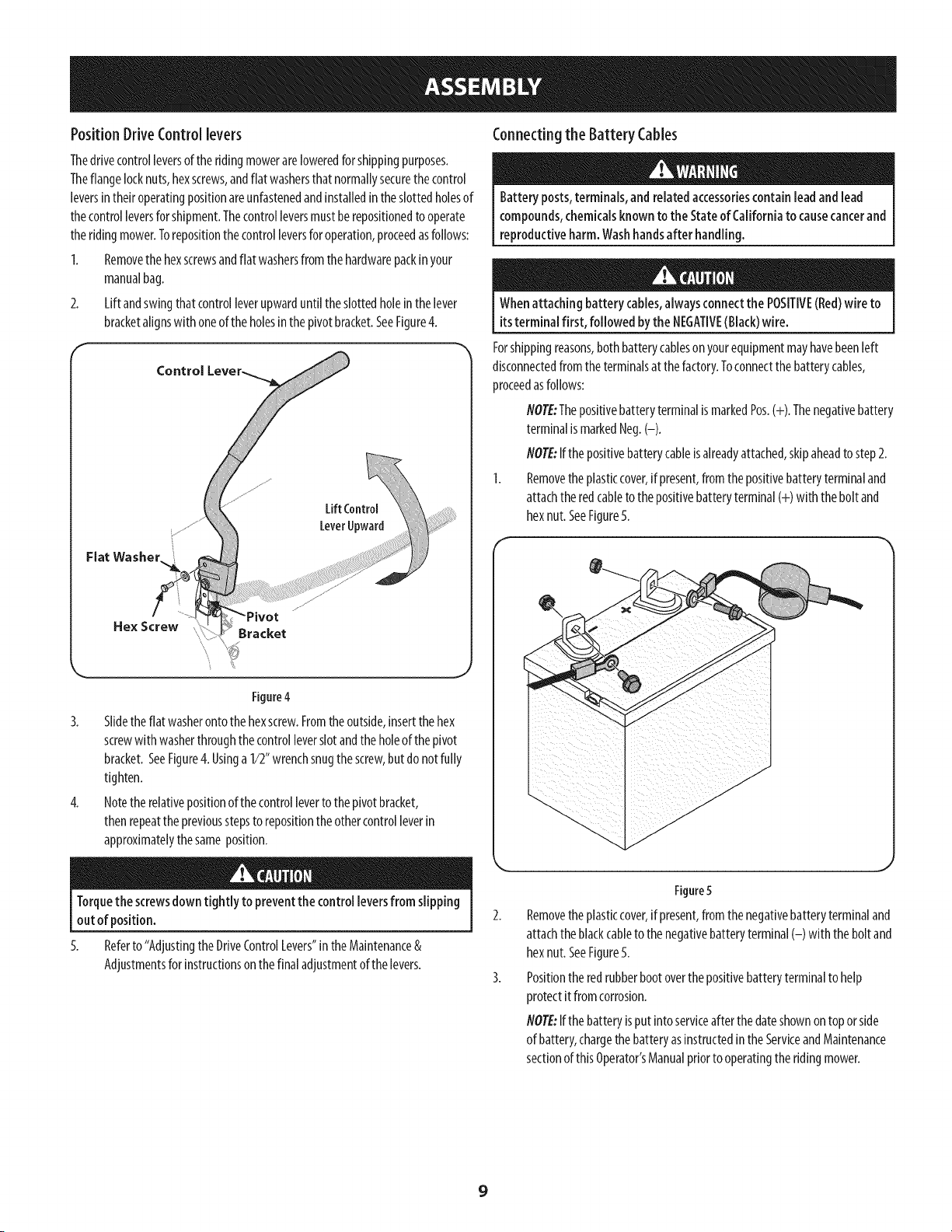
2. Lift andswingthatcontrolleverupwarduntil theslottedholeinthe lever
bracketalignswith oneof the holesin the pivotbracket.SeeFigure4.
Control
Flat Washer..
LiftControl
LeverUpward
Hex Screw
Bracket
Connectingthe Battery Cables
Battery posts,terminals, and relatedaccessoriescontain lead andlead
compounds,chemicalsknownto the Stateof Californiato causecancerand
reproductiveharm.Washhandsafter handling.
Whenattaching battery cables,alwaysconnect the POSITIVE(Red)wire to
itsterminal first, followed bythe NEGATIVE(Black)wire.
Forshippingreasons,bothbatterycablesonyourequipmentmayhavebeenleft
disconnectedfrom the terminalsat thefactory.Toconnectthebatterycables,
proceedasfollows:
flOTE:ThepositivebatteryterminalismarkedPos.(+). Thenegativebattery
terminalismarkedNeg.(-).
flOTE:Ifthepositivebatterycableisalreadyattached,skipaheadto step2.
1. Removethe plasticcover,if present,fromthepositivebatteryterminaland
attachthe redcabletothepositivebatteryterminal(+) with thebolt and
hexnut.SeeFigure5.
Figure4
3. Slidethe flat washerontothe hexscrew.Fromthe outside,insertthehex
screwwith washerthroughthecontrolleverslotandtheholeof thepivot
bracket.SeeFigure4.Usinga 1/2"wrenchsnugthescrew,butdo notfully
tighten.
4. Notethe relativepositionof thecontrolleverto thepivot bracket,
thenrepeatthe previousstepsto repositionthe othercontrolleverin
approximatelythesameposition.
Torquethe screwsdowntightly to preventthe control leversfrom slipping
out of position.
5.
Referto "AdjustingtheDriveControlLevers"intheMaintenance&
Adjustmentsforinstructionsonthe finaladjustmentof thelevers.
Figure 5
Removetheplasticcover,if present,fromthe negativebatteryterminaland
attachthe blackcableto thenegativebatteryterminal(-) with the bolt and
hexnut. SeeFigure5.
Positiontheredrubberbootoverthepositivebatteryterminalto help
protectit from corrosion.
flOTE:Ifthebatteryisput intoserviceafterthe dateshownontopor side
of battery,chargethe batteryasinstructedinthe ServiceandMaintenance
sectionof thisOperator'sManualpriorto operatingthe ridingmower.
9
Loading ...
Loading ...
Loading ...