Loading ...
Loading ...
Loading ...
KEEP SCROLL SAW IN REPAIR
• If power cord is worn or cut in any way, have it
replaced.
• Replace any damaged or missing part.
• Use parts list to order parts.
REPLACING BELTS
Refer to Figures 17, 18 and 19..
• Remove screw, washer and speed control knob
(Fig. 18, Key Nos. 1, 2 and 3).
• Remove three bolts from front panel (Fig. 18, Key
Nos. 4 and 6).
• Carefully pull front panel out and slide dust boot
OFF switch (Fig. 18, Key Nos. 5 and 7). Disconnect
wires from switch.
• Remove two screws (Fig. 19, Key No. 20) from the
base. Tip the saw on its side.
• Remove two bolts (Fig. 18, Key No. 33). Remove the
foot and bottom cover (Fig. 18, Key Nos. 31 and 32).
• The fan belt (Fig. 18, Key No. 30) can be removed
and replaced at this time.
• To replace the other belts, continue and remove the
pulley assembly from the base.
• Loosen two bolts and remove the blower assembly
(Fig. 18, Key Nos. 12 and 17). Remove flexible tube
(Fig. 18, Key No. 22) from blower assembly.
• Loosen two bolts and remove motor assembly
(Fig. 18, Key Nos. 23-29).
• Loosen set screw in shaft coupler (Fig. 19, Key Nos.
21 and 22).
• Remove four bolts and vari-speed pulley assembly
(Fig. 18, Key Nos. 12 and 15).
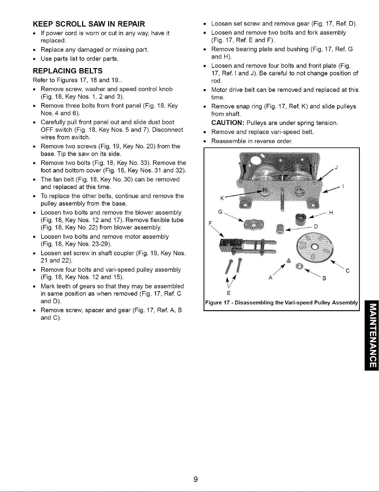
• Mark teeth of gears so that they may be assembled
in same position as when removed (Fig. 17, Ref. C
and D).
• Remove screw, spacer and gear (Fig. 17, Ref. A, B
and C).
• Loosen set screw and remove gear (Fig. 17, Ref. D).
• Loosen and remove two bolts and fork assembly
(Fig. 17, Ref. E and F).
• Remove bearing plate and bushing (Fig. 17, Ref. G
and H).
• Loosen and remove four bolts and front plate (Fig.
17, Ref. I and J). Be careful to not change position of
rod.
• Motor drive belt can be removed and replaced at this
time.
• Remove snap ring (Fig. 17, Ref. K) and slide pulleys
from shaft.
CAUTION: Pulleys are under spring tension.
• Remove and replace vari-speed belt.
• Reassemble in reverse order.
Figure 17 - Disassembling the Vari-speed Pulley Assembly
9
Loading ...
Loading ...
Loading ...