Loading ...
Loading ...
Loading ...
Tilting The Arm
Refer to Figure 12.
The arm of the scroll saw can be tilted from 0 to 45 ° to
the left by loosening the arm locking handle counter-
clockwise, tilting the arm to desired angle, and tighten-
ing the arm locking handle clockwise. Scale and pointer
show the angle of tilt.
Arm Locking
Handle
Figure 12 -Tilting the Arm
Holddown Assembly
Refer to Figure 13.
The holddown assembly is located at the right front of
the arm. To adjust pull up on lever, reposition holddown
foot to contact top of workpiece, and release lever. The
assembly includes a clear plastic blade guard and noz-
zle for dust collection.
Blade Guard
Dust Collection
Nozzle
Figure 13 - Holddown Assembly
Blade Lock/Release Lever
Refer to Figure 14.
WARNING: To avoid injury from accidental starting,
always turn switch OFF and remove power cord plug
from electrical outlet before removing or replacing blade.
The blade/lock release lever is located on the middle
right side of the arm and is used when changing
blades. Lever rests in the "lock" position. Pushing lever
back releases tension on the blade holders and blade
can be installed or removed.
Figure 14 - Blade Lock/Release Lever
INSTALLING AND REMOVING BLADES
Refer to Figures 14, 15 and 16, pages 7 and 8.
WARNING: To avoid injury from accidental starting,
always turn switch OFF and remove power cord plug
from electrical outlet before removing or replacing blade.
• Remove table insert. Release blade tension by push-
ing lock/release lever backwards (see Figure 14).
• Carefully remove blade from upper and lower hold-
ers.
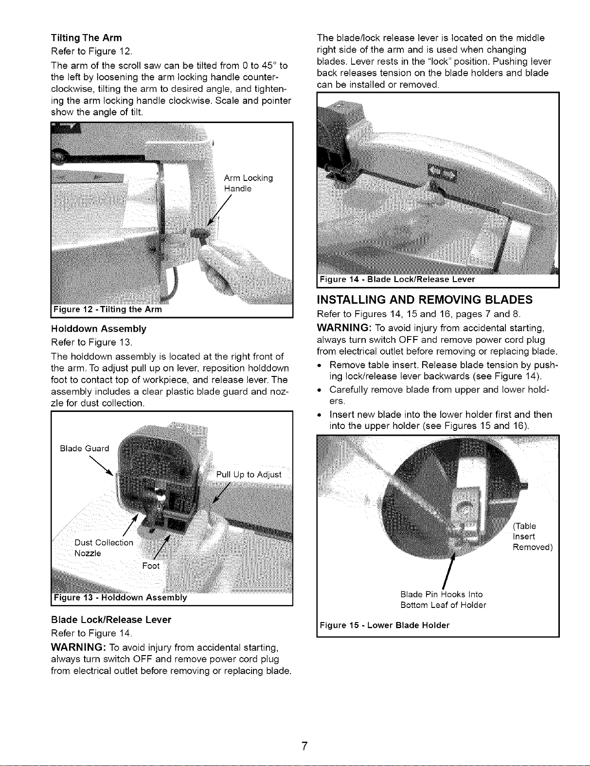
• Insert new blade into the lower holder first and then
into the upper holder (see Figures 15 and 16).
(Table
insert
Removed)
Blade Pin Hooks Into
Bottom Leaf of Holder
Figure 15 - Lower Blade Holder
Loading ...
Loading ...
Loading ...