Loading ...
Loading ...
Loading ...
ASSEMBLY INSTRUCTIONS
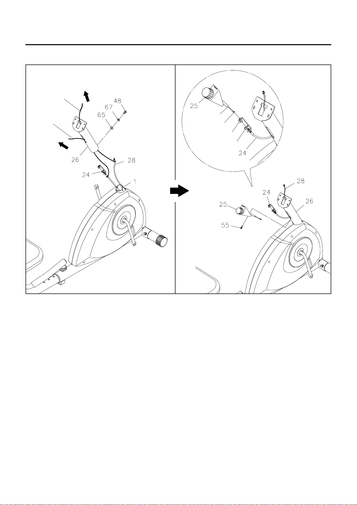
Bracket
Cable End
Spring Hook
Metal Fitting
Strap A
Strap B
A. B.
STEP 6
Refer to illustration A. Pull the ends of the TENSION CABLE(24) and SENSOR WIRE(28) out of the FRONT
FRAME(1). There are two straps attached inside of the METER POST(26) to assist when pulling the SENSOR
WIRE(28) and the TENSION CABLE(24) through the METER POST(26). Tie STRAP A to the plug end of
the SENSOR WIRE(28). Tie STRAP B to the BRACKET of the TENSION CABLE(24). Pull the STRAP A
from the square hole on the top of the METER POST(26) until the SENSOR WIRE(28) is pulled through and
extends out of the square hole. Pull the STRAP B from the square hole on the side of the METER POST(26)
until the TENSION CABLE(24) extends out of the side. Insert the METER POST(26) onto the FRONT
FRAME(1) and secure with BUTTON HEAD BOLT(M8x1.25x15mm)(48), LOCK WASHERS(M8)(67), and
ARC WASHERS(M8)(65).
STEP 7
Refer to illustration B and the inset drawing. Turn the TENSION KNOB(25) counterclockwise as far as it can
go, so the CABLE END extends out of the metal fitting as far as possible. Connect the CABLE END of the
TENSION KNOB(25) into the SPRING HOOK on the end of the TENSION CABLE(24). Pull on the CABLE
END of the TENSION KNOB(25) firmly so that enough cable is available to insert the CABLE END through
the slot in the BRACKET. Then insert the METAL FITTING on the CABLE END of the TENSION KNOB(25)
into the hole at the end of the slot in the BRACKET. Adjust the TENSION KNOB(25) and verify that the
SPRING HOOK moves when the TENSION KNOB(25) is adjusted. Attach the TENSION KNOB(25) to the
METER POST(26) with FLAT HEAD SCREW(M5x0.8x10mm)(55).
9
Loading ...
Loading ...
Loading ...