Loading ...
Loading ...
Loading ...
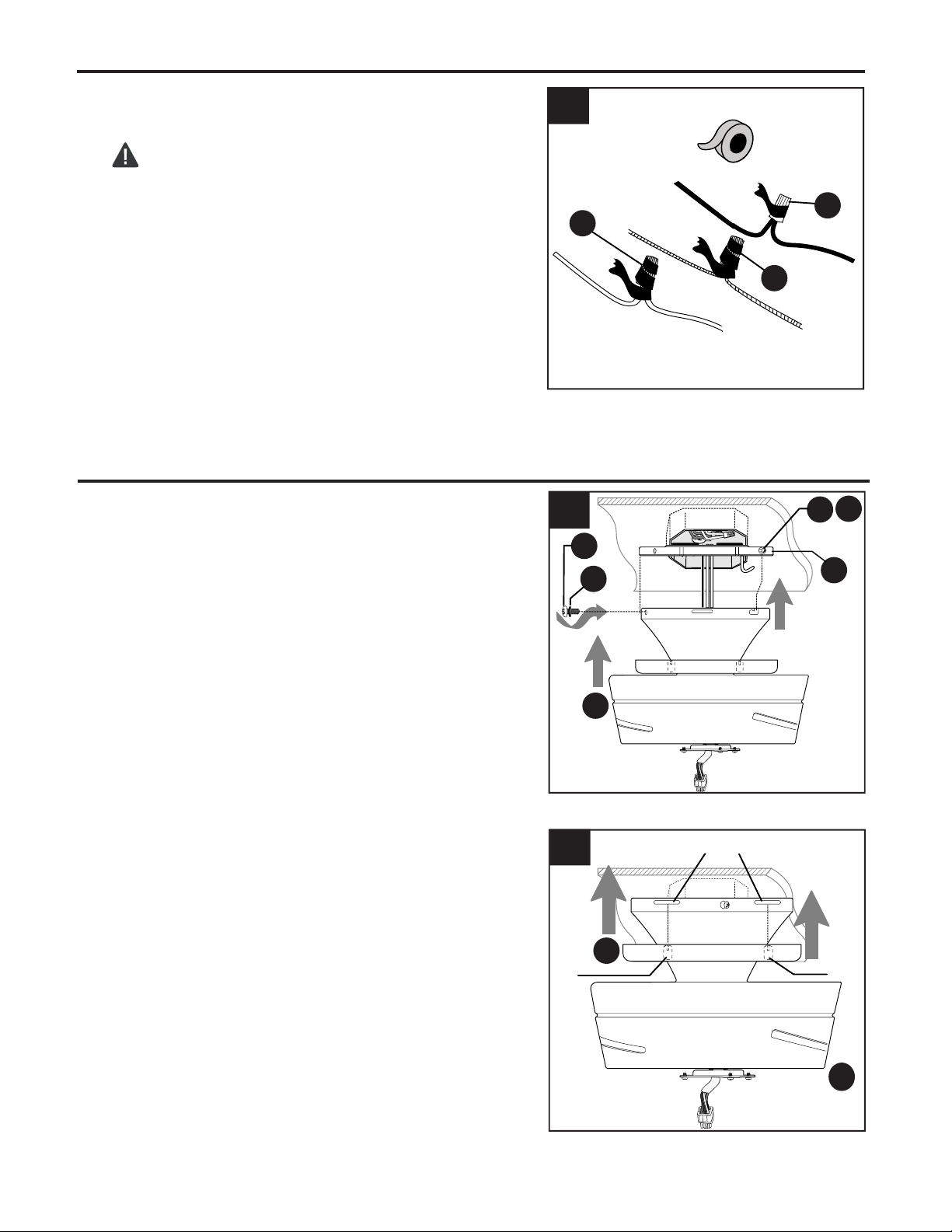
WIRING
Wrap electrical tape around each individual wire
connector (CC) down to the wire.
WARNING: Make sure no bare wire or wire
strands are visible after making connections.
Place green and white connections on opposite
side of box from the black and blue (if applicable)
connections.
Turn spliced/taped wires upward and gently push
wires and wire connectors (CC) into outlet box.
10
2.
CC
2
CC
CC
Locate four tabs inside canopy ring (B). Align tabs
in canopy ring (B) with four grooves at top of motor
assembly (C) and raise canopy (B) until you hear
tabs snap into grooves.
NOTE: Canopy ring (B) should fit flush to ceiling
when done correctly.
Remove motor assembly (C) from "J" hook and
slide top of motor assembly (C) over mounting plate
(A), aligning slotted holes in motor assembly (C)
with loosened mounting plate screws (J)/mounting
plate lock washers (I) in mounting plate (A). Twist
motor assembly (C) to lock. Re-insert the other two
mounting plate screws (J)/mounting plate lock
washers (I) previously removed (Step 5, page 8) to
secure motor assembly (C). Tighten all mounting
plate screws (J) securely.
1.
2.
1
2
C
J
I
A
Tab
J
C
I
FINAL INSTALLATION
B
Grooves
Tab
Loading ...
Loading ...
Loading ...