Loading ...
Loading ...
Loading ...
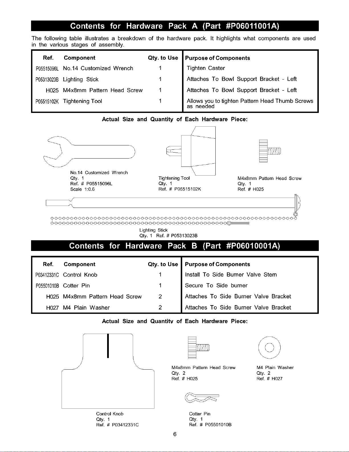
The following table illustrates a breakdown of the hardware pack. It highlights what components are used
in the various stages of assembly.
Ref. Component Qty. to Use
P05515096LNo.14 Customized Wrench 1
P05313023BLighting Stick 1
H025 M4x8mm Pattern Head Screw 1
P05515102KTightening Tool 1
Purpose of Components
Tighten Caster
Attaches To Bowl Support Bracket - Left
Attaches To Bowl Support Bracket - Left
Allows you to tighten Pattern Head Thumb Screws
as needed
Actual Size and Quantity of Each Hardware Piece:
/
No.14 Customized Wrench
Qty, 1
Ref. # PO5515096L
Scale 1:0.6
)
/
J
J
Tightening Tool
Qty. 1
Ref. # PO5515102K
M4xSmm Pattern Head Screw
Qty. 1
Ref. # H025
Lighting Stick
Qty. 1 Ref. # PO5313023B
Ref. Component Qty. to Use
P03412331CControl Knob 1
P05501010BCotter Pin 1
H025 M4x8mm Pattern Head Screw 2
H027 M4 Plain Washer 2
Purpose of Components
Install To Side Burner Valve Stem
Secure To Side burner
Attaches To Side Burner Valve Bracket
Attaches To Side Burner Valve Bracket
Actual Size and Quantity of Each Hardware Piece:
/
I
\
M4x8mm Pattern Head Screw M4 Plain Washer
Qty. 2 Qty. 2
Ref. # H025 Ref. # H027
Control Knob Cotter Pin
Qty. 1 Qty. 1
Ref. # P03412331C Ref. # PO5501010B
6
Loading ...
Loading ...
Loading ...