Loading ...
Loading ...
Loading ...
.
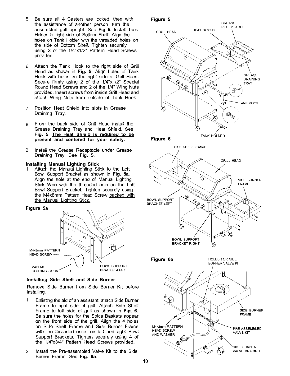
Be sure all 4 Casters are locked, then with
the assistance of another person, turn the
assembled gdll upright. See Fig 5. Install Tank
Holder to nght side of Bottom Shelf. Align the
holes on Tank Holder with the threaded holes on
the side of Bottom Shelf. Tighten securely
using 2 of the 1/4"xl/2" Pattern Head Screws
provided.
6.
Attach the Tank Hook to the right side of Grill
Head as shown in Fig. 5. Align holes of Tank
Hook with holes on the right side of Gdll Head.
Secure firmly using 2 of the 1/4"xl/2" Special
Round Head Screws and 2 of the 1/4" Wing Nuts
provided. Insert screws from inside Grill Head and
attach Wing Nuts from outside of Tank Hook.
7. Position Heat Shield into slots in Grease
Draining Tray.
.
From the back side of Grill Head install the
Grease Draining Tray and Heat Shield. See
Fig. 5. The Heat Shield is required to be
present and centered for your safety.
9. Install the Grease Receptacle under Grease
Draining Tray. See Fig. 5.
Installing Manual Lighting Stick
1. Attach the Manual Lighting Stick to the Left
Bowl Support Bracket as shown in Fig. 5a.
Align the hole at the end of Manual Lighting
Stick Wire with the threaded hole on the Left
Bowl Support Bracket. Tighten securely using
the M4x8mm Pattern Head Screw packed with
the Manual Lighting Stick.
Figure 5a
Figure 5
GRILL HEAD
Figure 6
BOWL SUPPORT
BRACKET-LEFT
GREASE
RECEPTACLE
HEAT SHtELD
TANK HOLDER
SIDE SHELF FRAME
/
GRILL HEAD
Z
GREASE
DRAINING
TRAY
SIDE BURNER
FRAME
M4xSmm PATTERN
HEAD SCREW__
BOWLSUPPORT
BRACKET-LEFT
Installing Side Shelf and Side Burner
Remove Side Burner from Side Burner Kit before
installing.
1.
Enlisting the aid of an assistant, attach Side Burner
Frame to right side of grill Attach Side Shelf
Frame to left side of grill as shown in Fig. 6.
Be sure the holes for the Spice Baskets appear
on the front side of the grill. Align the 4 holes
on Side Shelf Frame and Side Burner Frame
with the threaded holes on left and right Bowl
Support Brackets. Tighten securely using 4 of
the 1/4"x3/4" Pattern Head Screws provided.
BOWL SUPPORT
BRACKET-RIGHT
Figure 6a
M4x8mm PATTERN
HEAD SCREW
AND WASHER
HOLES FOR SIDE
BURNER VALVE KiT
SIDE BURNER
FRAME
;EMBLED
VALVE KIT
BURNER
VALVE BRACKET
2. Install the Pre-assembled Valve Kit to the Side
Bumer Frame. See Fig. 6a.
10
Loading ...
Loading ...
Loading ...