Loading ...
Loading ...
Loading ...
Page 5www.123filter.com | (678) 261-7611 | [email protected]
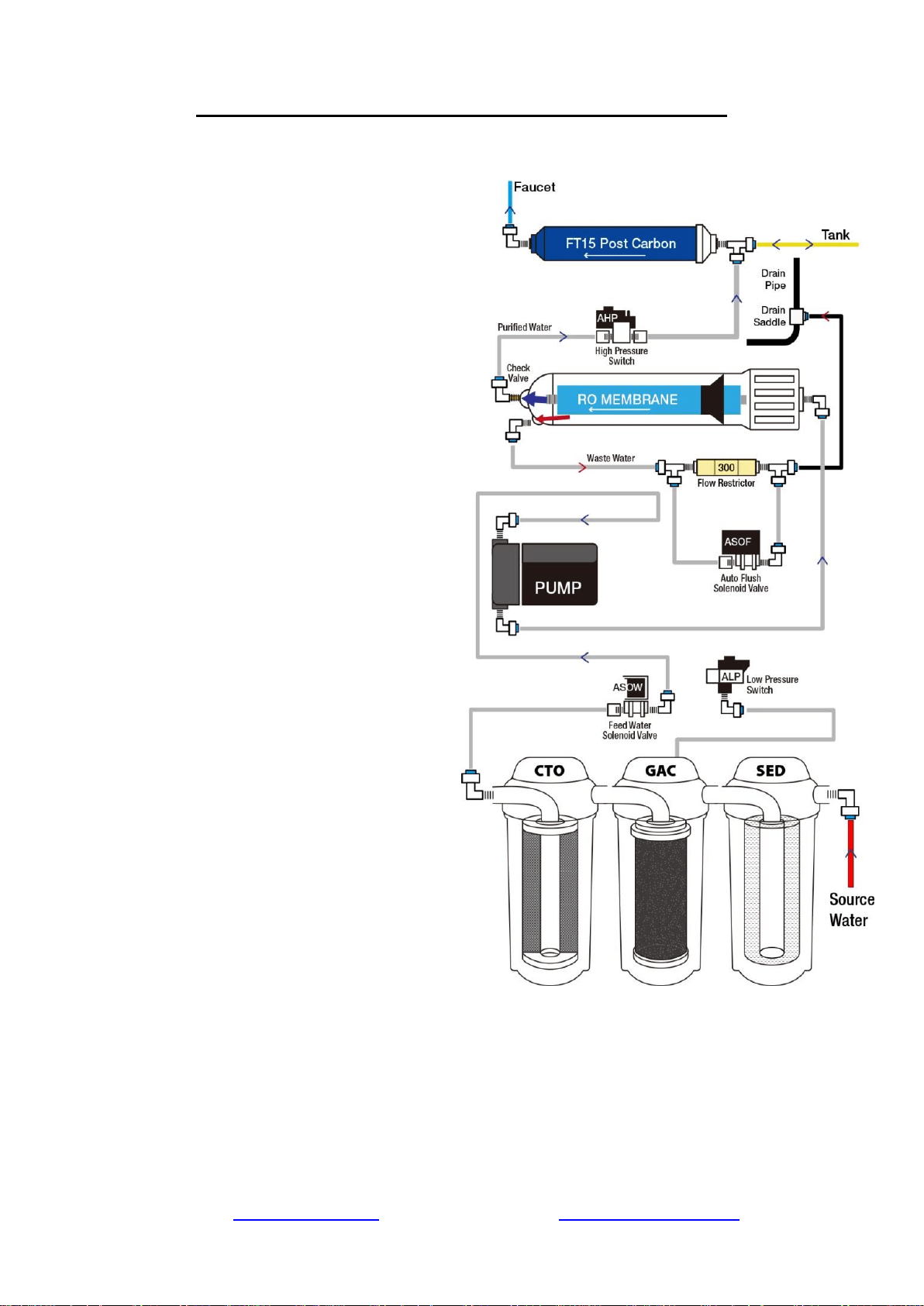
Understanding the Booster Pump and RO Process
1) Source water enters the system and
passes through the stage 1, 2, and 3 pre-
filters. Located between the pre-filters is
the Low Pressure Switch. This switch
turns on when the incoming water
pressure is 7 PSI or greater.
2) The High Pressure Switch turns on
when the pressure from the pressurized
tank is below 20 PSI, and turns off at 35
PSI (e.g. when tank is full).
3) When the Low Pressure Switch and
High Pressure Switch are both on, the
Feed Water Solenoid Valve opens,
allowing water to the Booster Pump.
4) The source water passes through the
Booster Pump, bringing it up to
approximately 80 PSI entering the
membrane housing.
5) Coming out of the RO membrane is a
pure water port and waste water port.
The RO water is forced through the
.0001 micron sized holes of the RO
membrane, and exits through the one
way Check Valve on the membrane’s
pure water exit port. The water rejected
by the RO membrane exits through the
waste water exit port. On the drain line
before the waste water is disposed is the
Flow Restrictor, limiting the amount of
drain water allowed out to keep pressure
in the system.
6) The pure water is then routed to the
pressurized storage tank. As the storage
tank fills, the tank pressure rises. When
the pressurized storage tank reaches 35
PSI, the tank pressure triggers the High
Pressure Switch off, shutting the booster
pump and system off.
7) When you open the RO faucet, the
water exits the tank, passes through the FT15 post carbon filter, and is dispensed from the
RO faucet. As the RO water is dispensed, the tank pressure will gradually drop back down,
triggering the High Pressure Switch back on to refill the water removed from the tank.
Loading ...
Loading ...
Loading ...